1
User Manual for EL5 Servo
User Manual for EL5 Servo
www.leadshine.com
1
User Manual for EL5 Servo
Introduction
Thanks for purchasing Leadshine EL5-series AC servo drivers, this instruction manual provides
knowledge and attention for using this driver.
Incorrect operation may cause unexpected accident, please read this manual carefully before using
product.
We reserve the right to modify equipment and documentation without prior notice.
We won’t undertake any responsibility with customer’s any modification of product, and the warranty of
product will be cancel at the same time.
Be attention to the following warning symbol:
Warning
indicates that the error operation could result in loss of life or serious injury.
Caution
indicates that the error operation could result in operator injured, also make equipment
damaged.
Attention
indicates that the error use may damage product and equipment.
Safety precautions
Warning
The design and manufacture of product doesn’t use in mechanic and system which have a threat to operator.
The safety protection must be provided in design and manufacture when using this product to prevent
incorrect operation or abnormal accident.
Acceptance
Caution
The product which is damaged or have fault is forbidden to use.
Transportation
Caution
The storage and transportation must be in normal condition.
Don’t stack too high, prevent falling.
The product should be packaged properly in transportation,
Don’t hold the product by the cable, motor shaft or encoder while transporting it.
The product can’t undertake external force and shock.
www.leadshine.com
2
User Manual for EL5 Servo
Installation
Caution
Servo Driver and Servo Motor:
Don’t install them on inflammable substance or near it to preventing fire hazard.
Avoid vibration, prohibit direct impact.
Don’t install the product while the product is damaged or incomplete.
Servo Driver:
Must install in control cabinet with sufficient safeguarding grade.
Must reserve sufficient gap with the other equipment.
Must keep good cooling condition.
Avoid dust, corrosive gas, conducting object, fluid and inflammable ,explosive object from invading.
Servo Motor:
Installation must be steady, prevent drop from vibrating.
Prevent fluid from invading to damage motor and encoder.
Prohibit knocking the motor and shaft, avoid damaging encoder.
The motor shaft can’t bear the load beyond the limits.
Wiring
Warning
The workers of participation in wiring or checking must possess sufficient ability do this job.
The wiring and check must be going with power off after five minutes
Ground the earth terminal of the motor and driver without fail.
The wiring should be connected after servo driver and servo motor installed correctly
After correctly connecting cables, insulate the live parts with insulator.
Caution
The wiring must be connected correctly and steadily, otherwise servo motor may run incorrectly, or damage
the equipment .
Servo motor U, V, W terminal should be connected correctly , it is forbidden to connect them directly to AC
power.
We mustn’t connect capacitors ,inductors or filters between servo motor and servo driver .
The wire and temperature-resistant object must not be close to radiator of servo driver and motor.
The freewheel diode which connect in parallel to output signal DC relay mustn’t connect reversely.
Debugging and running
Caution
Make sure the servo driver and servo motor installed properly before power on, fixed steadily, power
voltage and wiring correctly.
The first time of debugging should be run without loaded, debugging with load can be done after
confirming parameter setting correctly, to prevent mechanical damage because of error operation.
www.leadshine.com
3
User Manual for EL5 Servo
Using
Caution
Install a emergency stop protection circuit externally, the protection can stop running immediately to
prevent accident happened and the power can be cut off immediately.
The run signal must be cut off before resetting alarm signal, just to prevent restarting suddenly.
The servo driver must be matched with specified motor.
Don’t power on and off servo system frequently, just to prevent equipment damaged.
Forbidden to modify servo system.
Fault Processing
Warning
T he high voltage also will contain in several minutes even if the servo driver is powered off, please don’t
touch terminal strip or separate the wiring.
The workers of participation in wiring or checking must possess sufficient ability do this job.
Caution
The reason of fault must be figured out after alarm occurs, reset alarm signal before restart.
Keep away from machine, because of restart suddenly if the driver is powered on again after momentary
interruption(the design of the machine should be assured to avoid danger when restart occurs)
System selection
Attention
The rate torque of servo motor should be larger than effective continuous load torque.
The ratio of load inertia and motor inertia should be smaller than recommended value.
The servo driver should be matched with servo motor.
www.leadshine.com
4
User Manual for EL5 Servo
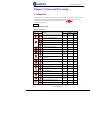
Table of Contents
User Manual for EL5 Servo ................................................................................................................................. 1
Introduction .......................................................................................................................................................... 2
Chapter 1 Introduction.......................................................................................................................................... 7
1.1 Product Introduction ............................................................................................................................... 7
1.2 Inspection of product .............................................................................................................................. 7
1.3 Product Appearance ................................................................................................................................ 7
Chapter 2 Installation ........................................................................................................................................... 9
2.1 Storage and Installation Circumstance ................................................................................................... 9
2.2 Servo Driver Installation ........................................................................................................................ 9
2.2.1 Installation Method ...................................................................................................................... 9
2.2.2 Installation Space .......................................................................................................................11
2.3 Servo Motor Installation....................................................................................................................... 12
Chapter 3 Wiring ................................................................................................................................................ 13
3.1 Wiring ................................................................................................................................................... 13
3.1.1 Wire Gauge ................................................................................................................................ 13
3.1.2 Position Control Mode .............................................................................................................. 14
3.1.3 Torque /Velocity Control Mode ................................................................................................. 15
3.2 Driver Terminals Function ................................................................................................................... 15
3.2.1 Control Signal Port-CN1 Terminal ............................................................................................ 15
3.2.2 Encoder Input Port-CN2 Terminal............................................................................................. 18
3.2.3 Communication Port.................................................................................................................. 18
3.2.4 Power Port ................................................................................................................................. 19
3.3 I/O Interface Principle .......................................................................................................................... 19
3.3.1 Switch Input Interface ............................................................................................................... 19
3.3.2 Switch Output Interface............................................................................................................. 20
3.3.3 Pulse Input Interface .................................................................................................................. 20
3.3.4 Analog Value Input Interface ..................................................................................................... 22
3.3.5 Servo Motor Encoder Input Interface ........................................................................................ 22
Chapter 4 Parameter ........................................................................................................................................... 23
4.1 Parameter List ...................................................................................................................................... 23
4.2 Parameter Function............................................................................................................................... 26
4.2.1【Class 0】Basic Setting ........................................................................................................... 26
4.2.2【Class 1】Gain Adjust ............................................................................................................. 29
4.2.3【Class 2】Vibration Suppression ............................................................................................. 33
4.2.4【Class 3】Velocity/ Torque Control ......................................................................................... 34
4.2.5【Class 4】I/F Monitor Setting ................................................................................................. 39
4.2.6【Class 5】Extended Setup ....................................................................................................... 43
4.2.7【Class 6】Special Setup........................................................................................................... 46
Chapter 5 Alarm and Processing ........................................................................................................................ 47
5.1 Alarm List ............................................................................................................................................. 47
5.2 Alarm Processing Method .................................................................................................................... 48
Chapter 6 Display and Operation ....................................................................................................................... 54
www.leadshine.com
5
User Manual for EL5 Servo
6.1 Introduction .......................................................................................................................................... 54
6.2 Panel Display and Operation ................................................................................................................ 55
6.2.1 Panel Operation Flow Figure ..................................................................................................... 55
6.2.2 Driver Operating Data Monitor ................................................................................................. 55
6.2.3 System Parameter Setting Interface........................................................................................... 58
6.2.4 Auxiliary Function ..................................................................................................................... 61
6.2.5 Saving parameter ....................................................................................................................... 62
6.2.6 Abnormal Alarm ........................................................................................................................ 63
Chapter 7 Trial Run ............................................................................................................................................ 64
7.1 Inspection Before trial Run .................................................................................................................. 64
7.1.1 Inspection on wiring .................................................................................................................. 64
7.1.2 Timing chart on power-up ......................................................................................................... 65
7.1.3 Timing chart on fault ................................................................................................................. 65
7.1.4 holding brake ............................................................................................................................. 65
7.2 Trial Run ............................................................................................................................................... 66
7.2.1 Jog Control ................................................................................................................................ 66
7.2.2 Position Control ......................................................................................................................... 67
7.2.3 Velocity Control......................................................................................................................... 68
7.2.4 Torque Control ........................................................................................................................... 69
7.3 Automatic Control Mode Run .............................................................................................................. 71
7.3.1 Operation Mode Selection ......................................................................................................... 71
7.3.2 Position Mode............................................................................................................................ 71
7.3.3 Velocity Mode ........................................................................................................................... 74
7.3.4 Torque Mode ............................................................................................................................. 77
Chapter 8 Product Specification ......................................................................................................................... 80
8.1 Driver Technical Specification ............................................................................................................. 80
8.2 Accessory selection .............................................................................................................................. 81
Chapter 9 Order Guidance .................................................................................................................................. 81
9.1 Capacity Selection ................................................................................................................................ 81
9.2 Electronic Gear Ratio ........................................................................................................................... 81
Appendix ............................................................................................................................................................ 82
How to debug theparameterof drivermatchedwith different servomotor........................................................................ 82
Contact us ........................................................................................................................................................... 83
www.leadshine.com
6
User Manual for EL5 Servo
Chapter 1 Introduction
1.1 Product Introduction
Since early 1990s, AC servo technology has been improved, AC servo is now widely used in the field of CNC
machine tools, printing and packaging machinery, textile machinery, and automated production line
automation.
The EL5 series AC servo motor &driver is the latest servo system that’s meets all demands for a variety of
machines which require high speed, high precision and high performance or which require simplified settings.
Talent feature:
◆Width ratio, constant torque
Speed ratio :1:5000, stable torque features from low speed to high speed
◆High-speed, high-precision
17
The maximum speed of the servo motor up to 5000rpm, rotation positioning accuracy up to 1/2 r.
◆Simple, flexible to control
By modifying the parameters of the servo system, the operating characteristics make the appropriate setting to
suit different requirements.
1.2 Inspection of product
1. You must check the following thing before using the products :
a. Check if the product is damaged or not during transportation.
b. Check if the servo driver & motor are complete or not.
c. Check the packing list if the accessories are complete or not
2. Type meaning
a. EL5 series servo driver
EL5-D-0750
Maximum Output Power
750:750W
High voltage AC servo drive (220 VAC)
b. Servo motor type
The EL5 series AC servo driver can be matched with a variety of domestic and foreign servo motor.
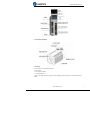
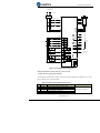
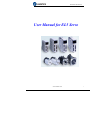
1.3 Product Appearance
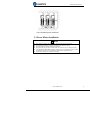
1. EL5 series AC servo driver appearance:
www.leadshine.com
7
User Manual for EL5 Servo
2. Servo motor appearance:
3. Accessory
EL5 series servo driver standard accessories
a. user manual
b.CN1 connector (DB44)
c. CN2 plug (DB15 pin)
〖Note〗: The ACH series driver supports the PC debugging software which can be downloaded from our
website
www.leadshine.com
8
User Manual for EL5 Servo
Chapter 2 Installation
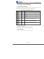
2.1 Storage and Installation Circumstance
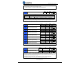
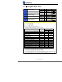
Table 2.1 Servo Driver, Servo Motor Storage Circumstance Requirement
Item
EL5 series driver
EL5 servo motor
Temperature
-20-80
-25-70
Humility
Under 90%RH (free from condensation) Under 80%RH(free from condensation)
Atmospheric Indoor(no exposure)no corrosive gas or
Indoor(no exposure)no corrosive gas or
environment
flammable gas, no oil or dust
flammable gas, no oil or dust
Altitude
Lower than 1000m
Lower than 2500m
2
Vibration
Less than 0.5G (4.9m/s ) 10-60Hz (non-continuous working)
Protection
IP00(no protection)
IP65
level
Table 2.2 Servo Driver, Servo Motor Installation Circumstance Requirement
Item
EL5 series driver
EL5 servo motor
Temperature
0-55
-25-40
Humility
Atmospheric
environment
Altitude
Vibration
Protection
level
Under 90%RH(free from condensation)
Under 90%RH(free from condensation)
Indoor(no exposure)no corrosive gas or Indoor(no exposure)no corrosive gas or
flammable gas, no oil or dust
flammable gas, no oil or dust
Lower than 1000m
Lower than 2500m
2
Less than 0.5G (4.9m/s ) 10-60Hz (non-continuous working)
IP00(no protection)
IP65
2.2 Servo Driver Installation
Notice
Must install in control cabinet with sufficient safeguarding grade.
Must install with specified direction and intervals, and ensure good cooling condition.
Don’t install them on inflammable substance or near it to prevent fire hazard.
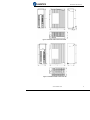
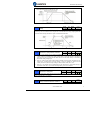
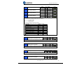
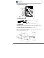
2.2.1 Installation Method
Install in vertical position ,and reserve enough space around the servo driver for ventilation.
Here is the installation diagram:
www.leadshine.com
9
User Manual for EL5 Servo
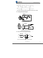
Figure 2.1 installation method of driver EL5-D-400
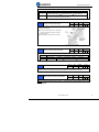
Figure 2.2 installation method of driver EL5-D-750
www.leadshine.com
10
User Manual for EL5 Servo
Figure 2.3 installation method of driver EL5-D-1000/EL5-D-1500
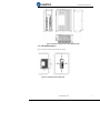
2.2.2 Installation Space
Reserve enough surrounding space for effective cooling.
Figure 2-4 Installation Space for Single Driver
www.leadshine.com
11
User Manual for EL5 Servo
Figure 2-5 Installation Space for several Drivers
2.3 Servo Motor Installation
Notice
Don’t hold the product by the cable, motor shaft or encoder while transporting it.
No knocking motor shaft or encoders, prevent motor by vibration or shock.
The motor shaft can’t bear the load beyond the limits.
Motor shaft does not bear the axial load, radial load, otherwise you may damage the motor.
Use a flexible with high stiffness designed exclusively for servo application in order to make
a radial thrust caused by micro misalignment smaller than the permissible value.
Install must be steady, prevent drop from vibrating.
www.leadshine.com
12
User Manual for EL5 Servo
Chapter 3 Wiring
Warning
The workers of participation in wiring or checking must possess sufficient ability do this job.
The wiring and check must be going with power off after five minutes.
Caution
Ground the earth terminal of the motor and driver without fail.
The wiring should be connected after servo driver and servo motor installed correctly
3.1 Wiring
3.1.1 Wire Gauge
(1)Power supply terminal TB
● Diameter: R, S, T, PE, U, V, W terminals diameter ≥ 1.5mm2 (AWG14-16), r, t terminal diameter ≥ 1.0 mm2
(AWG16-18).
● Grounding: The grounding wire should be as thick as possible, drive servo motor the PE terminal point
ground, ground resistance <100 Ω.
●Use noise filter to remove external noise from the power lines and reduce an effect of the noise generated by
the servo driver.
● Install fuse (NFB) promptly to cut off the external power supply if driver error occurs.
(2) The control signal CN1 feedback signal CN2
2
● Diameter: shielded cable (twisting shield cable is better), the diameter ≥ 0.12mm (AWG24-26), the shield
should be connected to FG terminal.
● Length of line: cable length should be as short as possible and control CN1 cable is no more than 3 meters,
the CN2 cable length of the feedback signal is no more than 20 meters.
● Wiring: be away from the wiring of power line, to prevent interference input.
●Install a surge absorbing element for the relevant inductive element (coil),: DC coil should be in parallel
connection with freewheeling diode reversely; AC coil should be in parallel connection with RC snubber
circuit.
Attention
Match the colors of the motor lead wires to those of the corresponding motor output terminals (U.V.W)
Never start nor stop the servo motor with this magnetic contactor.
Cable must be fixed steadily, avoid closing to radiator and motor to prevent reducing the properties of heat
insulation
www.leadshine.com
13
User Manual for EL5 Servo
3.1.2 Position Control Mode
1 phase or 3 phase
220VAC
Circuit Braker
Noise Filter
Magnetic Contactor
U
R
V
W
S
PE
T
r
CN2
CN1
t
PUL+
3
PUL-
4
DIR+
5
DIR-
6
23
24
COM+
1
Srom
2 4.7K
PL
7 4.7K
12~24V
RL
8
4.7K
4.7K
ZS
9
RDY
32
ALM
Pcod
33
A+
A-
25
B+
26
B-
27
Z+
28
Z-
22
5V
30
AGND
29
CHZ
39
AI1
41
AGN
D
43
A3I+
44
A3I-
Encoder
Output
-10V to +10V input
(Single -end)
-10V to +10V input
(Differential)
34
CN4
COM-
31
1 3 5
35
2 4 6
BRK
RS232
Figure 3-1 Positional Control Mode Wiring
www.leadshine.com
14
User Manual for EL5 Servo
3.1.3 Torque /Velocity Control Mode
Figure 3-2 Torque/Velocity Control Mode Wiring
3.2 Driver Terminals Function
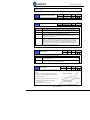
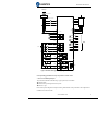
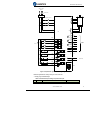
3.2.1 Control Signal Port-CN1 Terminal
The left on Figure 3.3 is control signal port CN1 of servo driver with DB44 connector; And, the right on
www.leadshine.com
15
User Manual for EL5 Servo
Figure 3.3 is SI input of the switch, SO output of the switch, analog A1 input, the A3 input from top to bottom.
Figure 3-3 Servo Driver Port Terminal
Table 3.1 Signal Explanation of Control Signal Port-CN1
Pin No
Signal
Input/output
1
COM+
input
2
SI1
input
3
4
5
6
PUL+
PULDIR+
DIR-
input
input
input
input
7
SI2
input
8
SI3
input
9
SI4
input
Name and Explanation
power supply positive terminal of the external input control signal,
12V ~ 24V
Digital input signal 1, default value is servo on signal in position
mode , low level available in default , the maximum voltage is 24V
input
positive and negative pulse input, respectively. TTL level (5V), the
rising edge available in default
positive and negative direction input, respectively. TTL level (5V),
optical coupling deadline available in default
Digital input signal 2, default value is forward run prohibited
(POT)signal in position mode ,high level available in default , the
maximum voltage is 24V input
Digital input signal 3, default value is reverse run prohibited (NOT)
signal in position mode , high level available in default , the
maximum voltage is 24V input
Digital input signal 4, default value is zero-speed clamp
(ZEROSPD) signal in position mode ,high level available in
www.leadshine.com
16
User Manual for EL5 Servo
10
SI5
input
11
SI6
input
12
SI9
input
13
SI7
input
14
SI8
input
22
23
24
25
26
27
28
29
30
31
+5V
A+
AB+
BZ+
ZOCZ
GND
COM-
output
output
output
output
output
output
output
output
output
output
32
SO2
output
33
SO1
output
34
SO3
output
35
SO4
output
36
37
SO5
SO6
output
output
39
AI1
input
40
+15VA
GND1
5VA
AI3+
AI3-
output
41
43
44
15-21,
38,42
Shell
default , the maximum voltage is 24V input
Digital input signal 5, default value is deviation counter clear input
in position mode , low level available in default , the maximum
voltage is 24V input
Digital input signal 6, low level available in default , the maximum
voltage is 24V input
Digital input signal 9, low level available in default , the maximum
voltage is 24V input
Digital input signal 7, low level available in default , the maximum
voltage is 24V input
Digital input signal 8, low level available in default , the maximum
voltage is 24V input
Reserved, encoder signal output +5V
Positive/negative differential output terminal of motor encoder A
phase
Positive/negative differential output terminal of motor encoder B
phase
Positive/negative differential output terminal of motor encoder Z
phase
Z signal OC output
Power ground of encoder signal output
Digital output signal commonality ground
Digital output signal 2 , default value is
Low resistor output in
servo ready output (S-RDY) in position
default . OC, the
mode , low level available in default
maximum
voltage/current is no
Digital output signal 1 , default value is
more than 30V, 50mA .
alarm output (ALM) in position mode ,
Recommend the
high level available in default
voltage : 12 V-24V.
Digital output signal 3 , default value is
Current :10mA
positioning complete (INP) in position
mode , high level available in default
Digital output signal 4, default value is
external brake release output
(BRK-OFF) in position mode , low level
available in default
Digital output signal 5
Digital output signal 6
Analog input 1, voltage input range : -10 - 10V , input resistor
20KΩ
Reserved, output voltage:15V, current :less than 50mA
output
Reserve,+15V ground
input
input
The positive/ negative terminal of analog input 3, voltage input
range -10-10V, input resistor : 20KΩ
NC
/
Not connection
FG
/
Shield ground
www.leadshine.com
17
User Manual for EL5 Servo
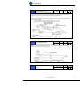
3.2.2 Encoder Input Port-CN2 Terminal
Table 3.2 Encoder Input Port-CN2 Terminal Signal Explain
Pin
Signal
Name
1
EA+
Encoder channel A+ input
Terminal Arrangement Figure
2
EB+
Encoder channel B+ input
3
EGND
Signal ground
4
Hall W+
Hall sensor W+ input
5
Hall U+
Hall sensor U+ input
6
FG
Ground terminal for shielded
7
EZ+
Encoder channel Z+ input
8
EZ-
Encoder channel Z- input
9
Hall V+
Hall sensor V+ input
10
Hall V-
Hall sensor V- input
11
EA-
Encoder channel A- input
12
EB-
Encoder channel B- input
13
VCC
+5V for encoder power supply
14
Hall W-
Hall sensor W- input
15
Hall U-
Hall sensor U- input
1
6
11
2
7
12
3
8
13
4
9
14
5
10
15
EA+
FG
EAEB+
EZ+
EBEZHW+
HV+
HWHU+
HVHU-
GND
+5V
3.2.3 Communication Port
Table 3.3 Signal Explanation of connection and debugging Port-CN4
connect PC or STU using dedicated series cable, prohibited to insert if power on.
RS232
and suggest to use twisted-pair or shielded wire. the length of wire is less than 2 meter
RS485
Recommend shield twisted-pair.
Terminal
1
2
3
4
5
6
signal
GND
TxD
5V
RxD
RS485+
RS485-
name
Power ground
sending terminal of RS232
Reserved, the current is less than 50mA
received terminal of RS232
Reserve,RS485+/A
Reserve,RS485-/B
Table 3.4 signal explanation of driver interconnection interface-CN3
RS485
Terminal
1
2
3
4
5
6
Recommend shield twisted-pair.
signal
name
GND
Power ground
NC
Not connect
5V
Reserve, the current is less than 50mA
NC
Not connect
RS485+ Reserve,RS485+/A
RS485Reserve,RS485-/B
www.leadshine.com
18
User Manual for EL5 Servo
3.2.4 Power Port
Table 3.5 Main Power Input Port-CN5
Terminal
1
2
3
4
5
Signal
R
S
T
BR
P+
Name
the main power input: connecting 3-phase 220Vac or single phase 220Vac,
For single phase 220V ,recommend to connect to the R and T.
Outside brake resistor input terminal
DC bus voltage+
external brake resistor
connect between BR1 and P+
Table 3.6 Control Power Input Port-CN6
Terminal
1
2
3
4
5
Signal
U
V
W
PE
r
t
Name
3 phase motor power input
Frame ground
Control power input 1
Control power input 2
Control power voltage range between 1 and 2:
85Vac-265Vac
3.3 I/O Interface Principle
3.3.1 Switch Input Interface
Figure 3-4 Switch Input Interface
The user provide power supply, DC 12-24V, current≥100mA
Notice: if current polar connect reversely, servo driver doesn’t run.
www.leadshine.com
19
User Manual for EL5 Servo
3.3.2 Switch Output Interface
Driver side
Max 50mA
12~24Vdc
COMFigure 3.5 Switch Output Interface
(1) The user provide the external power supply . However, if current polarity connects reversely, servo driver
is damaged.
(2) The output of the form is open-collector, the maximum voltage is 25V, and maximum current is 50mA.
Therefore, the load of switch output signal must match the requirements. If you exceed the requirements or
output directly connected with the power supply, the servo drive is damaged.
(3) If the load is inductive loads relays, etc., there must be anti-parallel freewheeling diode across the load. If
the freewheeling diode is connected reversely, the servo drive is damaged.
3.3.3 Pulse Input Interface
Figure 3-6 Pulse Input Interface Differential Drive Mode
Driver side
VCC
R
DIR+
270R
DIR-
R
PUL+
270R
PUL-
www.leadshine.com
20
User Manual for EL5 Servo
Vcc =12V,
R = 1K, 0.25W
Vcc =24V, R = 2K, 0.25W
Figure3-7 Pulse Input Interface Single Terminal Drive Mode
(1) In order to transmit pulse data properly , we recommend using the differential drive mode.
(2) The differential drive mode, AM26LS31, MC3487 or similar RS422 line drive.
(3) Using of single-ended drive will cause reduction of the operation frequency. The value of the resistance R
depends on pulse input circuit and the external voltage,while drive current should be at the range of 10 15mA and the maximum voltage is no more than 25V .
Recommendation:
VCC = 24V, R = 1.3 to 2KΩ;
VCC = 12V, R = 510 ~ 820Ω;
VCC = 5V, R = 82 ~~ 120Ω.
(4) The user provide external power supply for single-ended drive. However, if current polarity connect
reversely, servo driver is damaged. However, if current polarity connects reversely, servo driver is
damaged.
(5) The form of pulse input is the following form 3.7 below, while the arrows indicates the count .
Table 3.7 Pulse Input Form
Pulse command form
CCW
CW
Pulse symbol
Parameter setting value
Pulse + direction
The form of pulse input timing parameter is the following form 3.8 below. The 4 times pulse frequency ≤
500kH if 2-phase input form is used.
Table 3.8 the parameters of pulse input time sequence
parameter
tck
th
tl
t rh
t rl
ts
tqck
tqh
tql
tqrh
tqrl
tqs
Differential drive input
>2μs
>1μs
>1μs
<0.2μs
<0.2μs
Single-ended drive input
>5μs
>2.5μs
>2.5μs
<0.3μs
<0.3μs
>1μs
>8μs
>4μs
>4μs
<0.2μs
<0.2μs
>1μs
>2.5μs
>10μs
>5μs
>5μs
<0.3μs
<0.3μs
>2.5μs
www.leadshine.com
21
User Manual for EL5 Servo
Figure 3.8 pulse + direction input interface timing (the maximum of pulse frequency : 500KHZ)
3.3.4 Analog Value Input Interface
Figure 3-9 Analog AI1 Input Interface
Figure 3-10 Analog AI3 Input Interface
3.3.5 Servo Motor Encoder Input Interface
Figure 3-11 Servo Motor optical-electrical Encoder Input Interface
www.leadshine.com
22
User Manual for EL5 Servo
Chapter 4 Parameter
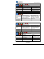
4.1 Parameter List
Mode
Parameter Number
Classify
Name
P
S
T
P
S
T
【Class 0】
01
control mode setup
P
S
T
02
real-time auto-gain tuning
P
S
T
Basic
setting
P
S
T
Number
04
selection of machine stiffness at real-time
auto-gain tuning
Inertia ratio
P
06
command pulse rotational direction setup
P
07
command pulse input mode setup
P
09
1st numerator of electronic gear
P
10
denominator of electronic gear
03
P
S
T
11
output pulse counts per one motor revolution
P
S
T
12
reversal of pulse output logic
P
S
T
13
1st torque limit
14
position deviation excess setup
00
01
gain of 1st position loop
gain of 1st velocity loop
P
【Class 1】
P
P
S
T
P
S
T
02
time constant of 1st velocity loop integration
P
S
T
03
filter of 1st velocity detection
P
S
T
04
time constant of 1st torque filter
05
gain of 2nd position loop
gain of 2nd velocity loop
time constant of 2nd velocity loop integration
Gain Adjust
P
P
S
T
P
S
T
06
07
P
S
T
08
filter of 2nd velocity detection
P
S
T
09
10
time constant of 2nd torque filter
Velocity feed forward gain
P
P
11
Velocity feed forward filter
P
S
12
Torque feed forward gain
P
S
13
Torque feed forward filter
P
S
14
2nd gain setup
P
15
17
Control switching mode
Control switching level
P
18
Control switch hysteresis
P
19
Gain switching time
P
35
Positional command filter setup
36
Encoder feedback pulse digital filter setup
【Class 2】
00
adaptive filter mode setup
Vibration
01
1st notch frequency
T
P
P
S
P
S
P
S
T
T
www.leadshine.com
23
User Manual for EL5 Servo
P
S
T
Restrain
02
1st notch width selection
P
S
T
Function
03
1st notch depth selection
P
S
T
04
2nd notch frequency
P
S
T
05
2nd notch width selection
P
S
T
06
2nd notch depth selection
P
22
Positional command smooth filter
P
23
Positional command FIR filter
S
【Class 3】
00
Velocity setup internal/external switching
S
Speed,
Torque
01
02
Speed command rotational direction selection
Speed command input gain
Control
S
T
03
Speed command reversal input
S
04
1st speed setup
S
05
2nd speed setup
S
06
3rd speed setup
S
07
4th speed setup
S
08
5th speed setup
S
09
6th speed setup
S
10
7th speed setup
S
11
8th speed setup
S
12
Acceleration time setup
S
13
Deceleration time setup
S
14
Sigmoid acceleration/deceleration time setup
15
Speed zero-clamp function selection
T
16
Speed zero-clamp level
T
18
Torque command direction selection
T
19
Torque command input gain
T
T
20
21
Torque command input reversal
Speed limit value 1
24
maximum speed of motor rotation
SI 1 input selection
S
S
P
S
T
P
S
T
【Class 4】
00
P
S
T
I/F Monitor
01
SI 2 input selection
P
S
T
Setting
02
SI 3 input selection
P
S
T
03
SI 4 input selection
P
S
T
04
SI 5 input selection
P
S
T
10
SO 1 output selection
P
S
T
P
S
T
11
12
SO 2 output selection
SO 3 output selection
P
S
T
13
SO 4 output selection
P
S
T
22
Analog input 1(AI 1) offset setup
P
S
T
23
Analog input 1(AI 1) filter
P
S
T
28
Analog input 3(AI 3) offset setup
P
S
T
29
Analog input 3(AI 3) filter
31
Positioning complete range
P
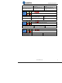
www.leadshine.com
24
User Manual for EL5 Servo
P
32
Positioning complete output setup
P
33
INP hold time
34
Zero-speed
35
Speed coincidence range
P
S
T
S
P
S
T
36
At-speed
P
S
T
37
Mechanical brake action at stalling setup
P
S
T
38
Mechanical brake action at running setup
P
S
T
39
Brake action at running setup
P
【Class 5】
00
2nd numerator of electronic gear
P
Extended
01
3rd numerator of electronic gear
P
Setup
02
4th numerator of electronic gear
P
S
T
03
Denominator of pulse output division
P
S
T
06
Sequence at servo-off
P
S
T
08
Main power off LV trip selection
P
S
T
09
Main power off detection time
P
S
T
13
Over-speed level setup
P
S
T
15
I/F reading filter
P
S
T
28
LED initial status
P
S
T
29
RS232 baud rate setup
P
S
T
30
RS485 baud rate setup
P
S
T
31
Axis address
P
S
T
35
Front panel lock setup
P
S
T
【Class 6】
03
JOG trial run command torque
P
S
T
Special
04
JOG trial run command speed
P
S
T
Setup
08
Positive direction torque compensation value
P
S
T
09
Negative direction torque compensation value
P
20
21
distance of trial running
waiting time of trial running
P
22
cycling times of trial running
P
www.leadshine.com
25
User Manual for EL5 Servo
4.2 Parameter Function
Here is the explanation of parameters ,you can check them or modify the value using software Protuner or the
front panel of driver.
4.2.1【Class 0】Basic Setting
Pr0.01*
Control Mode Setup
Set using control mode
Content
Setup value
1st mode
0
Position
1
Velocity
2
Torque
3
Position
4
Position
5
Velocity
Pr0.02
Range
unit
default
0 -2
-
0
Related
control mode
P
S
T
When you set up the combination mode of 3.4.5, you
can select either the 1st or the 2nd with control mode
switching input(C-MODE).
When C-MODE is open, the 1st mode will be selected.
When C-MODE is shorted, the 2nd mode will be
selected.
2nd mode
Velocity
Torque
Torque
Real-time Auto-gain Tuning
Range
unit
default
Related
control mode
0 -2
0
P
S
T
You can set up the action mode of the real-time auto-gain tuning.
Setup value
mode
Varying degree of load inertia in motion
0
invalid
Real-time auto-gain tuning function is disabled.
Basic mode. do not use unbalanced load, friction compensation or
1
standard
gain switching
Main application is positioning. it is recommended to use this
2
positioning mode on equipment without unbalanced horizontal axis, ball screw
driving equipment with low friction, etc.
Caution: If pr0.02=1 or 2 , you can’t modify the values of pr1.01 – pr1.13, the values of them
depend on the real-time auto-gain tuning ,all of them are set by the driver itself.
Pr0.03
selection of machine stiffness at real
time auto gain tuning
Range
0 -31
You can set up response while the real-time auto-gain tuning is valid.
unit
default
-
11
Related
control mode
P
S
T
Notice: Higher the setup value, higher the velocity response and servo stiffness will be obtained.
However, when increasing the value, check the resulting operation to avoid oscillation or vibration.
Control gain is updated while the motor is stopped. If the motor can’t be stopped due to excessively
low gain or continuous application of one-way direction command ,any change made to Pr0.03 is not
www.leadshine.com
26
User Manual for EL5 Servo
used for update. If the changed stiffness setting is made valid after the motor stopped, abnormal
sound or oscillation will be generated. To prevent this problem, stop the motor after changing the
stiffness setting and check that the changed setting is enabled.
Pr0.04
Inertia ratio
Range
unit
0 -10000
%
default
250
Related
control mode
P
S
T
You can set up the ratio of the load inertia against the rotor(of the motor)inertia.
Pr0.04=( load inertia/rotate inertia)×100%
Notice:
If the inertia ratio is correctly set, the setup unit of Pr1.01 and Pr1.06 becomes (Hz). When the inertia
ratio of Pr0.04 is larger than the actual value, the setup unit of the velocity loop gain becomes larger,
and when the inertia ratio of Pr0.04 is smaller than the actual value, the setup unit of the velocity
loop gain becomes smaller.
Pr0.06*
Command Pulse Rotational Direction
Setup
Range
unit
default
0 -1
-
0
Range
unit
default
0 -3
-
3
Related
control mode
P
Set command pulse input rotate direction, command pulse input type
Pr0.07*
Pr0.06
Command Pulse Input Mode Setup
Pr0.07
0
1
Command Pulse Format
Signal
0 or 2
90 phase difference
2-phase pulse(A phase +B
phase)
Pulse
sign
1
Positive direction pulse +
negative direction pulse
Pulse
sign
3
Pulse + sign
Pulse
sign
0 or 2
90 phase difference
2 phase pulse(A phase +B
phase)
Pulse
sign
1
Positive direction pulse +
negative direction pulse
Pulse
sign
3
Pulse + sign
Pulse
sign
Positive
Direction
Command
P
Negative
Direction
Command
Command pulse input signal allow largest frequency and smallest time width
Permissible Max. Smallest Time Width
PULS/SIGN Signal Input I/F
Input Frequency
t1
t2
t3
t4
Pulse
Long distance interface
500kpps
2
1
1
1
series
Open-collector
output
200kpps
5
2.5
2.5
2.5
interface
www.leadshine.com
Related
control mode
t5
1
2.5
t6
1
2.5
27
User Manual for EL5 Servo
Pr0.09
1st numerator of electronic gear
Range
unit
default
1-32767
-
1
Related
control mode
P
Set the numerator of division/multiplication operation made according to the command pulse input.
Pr0.10
denominator of electronic gear
Range
unit
default
Related
control mode
1-32767
1
P
Set the denominator of division/multiplication operation made according to the command pulse
input.
Pr0.09
Pr0.10
Command division/multiplication operation
1-32767
Pr0.11*
1-32767
Output pulse counts per one motor
revolution
Range
unit
1-2500
P/r
default
2500
Related
control mode
P
S
T
Set the numerator of division/multiplication operation made according to the command pulse input.
Range
Pr5.03*
denominator of pulse output division
unit
1-2500
default
Related
control mode
-
250 P
S
T
0
Combination of Pr0.11 Output pulse counts per one motor revolution and Pr5.03 Denominator of
pulse output division
Pr0.11 Pr5.03
Pulse output process
1-2500 1-2500
Pulse output resolution after dividing double frequency 4 times
Pr0.12*
reversal of pulse output logic
Range
unit
default
Related
control mode
0 -1
0
P
S
T
You can set up the B phase logic and the output source of the pulse output. With this parameter, you
can reverse the phase relation between the A-phase pulse and B-phase pulse by reversing the B-phase
logic.
< reversal of pulse output logic >
Pr0.12
B-phase Logic
CCW Direction Rotation
CW Direction Rotation
0
Non-Reversal
A phase
A phase
www.leadshine.com
28
User Manual for EL5 Servo
1
Reversal
B phase
B phase
A phase
A phase
B phase
B phase
Range
Pr0.13
1st Torque Limit
Pr0.14
Position Deviation Excess Setup
unit
default
Related
control mode
0 -500
%
300
P
S
T
You can set up the limit value of the motor output torque, as motor rate current %, the value can’t
exceed the maximum of output current.
Range
unit
default
Related
control mode
0 -500 0.1 rev
200 P
Set excess range of positional deviation by the command unit(default).Setting the value too small
will cause Err18.0 (position deviation excess detection)
4.2.2【Class 1】Gain Adjust
Pr1.00
1st gain of position loop
Pr1.01
1st gain of velocity loop
Pr1.02
1st Time Constant of Velocity Loop
Integration
Range
unit
default
Related
control mode
0 -30000 0.1/s
320 P
You can determine the response of the positional control system. Higher the gain of position loop you
set, faster the positioning time you can obtain. Note that too high setup may cause oscillation.
Range
unit
default
Related
control mode
0 -32767 0.1Hz
180 P
S
T
You can determine the response of the velocity loop. In order to increase the response of overall
servo system by setting high position loop gain, you need higher setup of this velocity loop gain as
well. However, too high setup may cause oscillation.
Range
unit
default
Related
control mode
0 -10000 0.1ms
310
P
S T
You can set up the integration time constant of velocity loop, Smaller the set up, faster you can
dog-in deviation at stall to 0.The integration will be maintained by setting to”9999”.The integration
effect will be lost by setting to”10000”.
Related
Range unit default control
mode
1st Filter of Velocity Detection
Pr1.03
0 -31
15
P
S T
You can set up the time constant of the low pass filter (LPF) after the speed detection, in 32 steps
(0 to 31).Higher the setup, larger the time constant you can obtain so that you can decrease the motor
noise, however, response becomes slow.
You can set the filter parameters through the loop gain, referring to the following table:
www.leadshine.com
29
User Manual for EL5 Servo
Set
Value
0
1
2
3
4
5
6
7
8
9
10
11
12
13
14
15
Pr1.04
Pr1.05
Speed Detection Filter
Cut-off Frequency(Hz)
2500
2250
2100
2000
1800
1600
1500
1400
1300
1200
1100
1000
950
900
850
800
Set
Value
16
17
18
19
20
21
22
23
24
25
26
27
28
29
30
31
Speed Detection Filter
Cut-off Frequency(Hz)
750
700
650
600
550
500
450
400
350
300
250
200
175
150
125
100
2nd Time Constant of torque filter
2nd gain of position loop
Pr1.06
2nd gain of velocity loop
Pr1.07
2nd Time Constant of Velocity Loop
Integration
Pr1.08
2nd Filter of Velocity Detection
Pr1.09
2nd Time Constant of torque filter
Pr1.10
Velocity feed forward gain
Pr1.11
Velocity feed forward filter
Range
unit
0 -2500
0.01ms
126
Range
unit
default
0 -30000
0.1/s
default
380
P
S T
Related
control mode
P
Related
control mode
Range
unit
0 -32767
0.1Hz
180
Range
unit
default
Related
control mode
0 -10000
0.1ms
10000
P
unit
default
Related
control mode
Range
default
Related
control mode
0 -31
-
15
Range
unit
default
P
P
S
T
S T
S T
Related
control mode
0 -2500
0.01ms
126
P
S T
Position loop, velocity loop, velocity detection filter, torque command filter have their 2 pairs of gain
or time constant(1st and 2nd).
Range
unit
default
Related
control mode
0 -1000
0.1%
300
P
Multiply the velocity control command calculated according to the internal positional command by
the ratio of this parameter and add the result to the speed command resulting from the positional
control process.
Range
unit
default
Related
control mode
0 -6400
0.01ms
50
P
Set the time constant of 1st delay filter which affects the input of speed feed forward.
(usage example of velocity feed forward)
The velocity feed forward will become effective as the velocity feed forward gain is gradually
increased with the speed feed forward filter set at approx.50 (0.5ms). The positional deviation during
www.leadshine.com
30
User Manual for EL5 Servo
operation at a constant speed is reduced as shown in the equation below in proportion to the value of
velocity feed forward gain.
Position deviation [ unit of command]=command speed [ unit of command /s]/position loop
gain[1/s]×(100-speed feed forward gain[%]/100
Pr1.12
Torque feed forward gain
Pr1.13
Torque feed forward filter
Pr1.15
Mode of position control switching
Range
unit
default
Related
control mode
0 -1000
0.1%
0
P
S
Multiply the torque control command calculated according to the velocity control command by
the ratio of this parameter and add the result to the torque command resulting from the velocity
control process.
To use torque feed forward, correctly set ratio of inertia. Set the inertia ratio that can be calculated
from the machine specification to Pr0.04 inertia ratio.
Positional deviation at a constant acceleration/deceleration can be minimized close to 0 by
increasing the torque forward gain .this means that positional deviation can be maintained at near
0 over entire operation range while driving in trapezoidal speed pattern under ideal condition
where disturbance torque is not active.
Range
unit
default
Related
control mode
0 -6400
0.01ms
0
P
S
Set up the time constant of 1st delay filter which affects the input of torque feed forward.
zero positional deviation is impossible in actual situation because of disturbance torque. as with
the velocity feed forward, large torque feed forward filter time constant decreases the operating noise
but increases positional deviation at acceleration change point.
Setting
value
0
1
2
3
4
5
6
Switching condition
Range
unit
default
0 -10
-
0
Related
control mode
P
Gain switching condition
Fixed to 1st gain
Fixed to 2nd gain
with gain switching
input
Fixed to the 1st gain (Pr1.00-Pr1.04)
Fixed to the 2nd gain (Pr1.05-Pr1.09)
1st gain when the gain switching input is open.
2nd gain when the gain switching input is connected to com- .
If no input signal is allocated to the gain switching input, the
1st gain is fixed.
Torque command is Shift to the 2nd gain when the absolute value of the torque
large
command exceeded (level + hysteresis)[%]previously with the
1st gain.
Return to the 1st gain when the absolute value of the torque
command was kept below (level + hysteresis) [%]previously
during delay time with the 2nd gain.
reserve
reserve
Speed command is
Valid for position and speed controls.
large
Shift to the 2nd gain when the absolute value of the speed
command exceeded (level + hysteresis)[r/min]previously with
the 1st gain.
Return to the 1st gain when the absolute value of the speed
command was kept below (level + hysteresis) [r/min]
previously during delay time with the 2nd gain.
Position deviation is Valid for position control.
large
Shift to the 2nd gain when the absolute value of the positional
deviation exceeded (level + hysteresis)[pulse] previously with
the 1st gain.
Return to the 1st gain when the absolute value of the
www.leadshine.com
31
User Manual for EL5 Servo
positional deviation was kept below (level +
hysteresis)[r/min]previously during delay time with the 2nd
gain.
Unit of level and hysteresis [pulse] is set as the encoder
resolution for positional control.
7
position command
Valid for position control.
exists
Shift to the 2nd gain when the positional command was not 0
previously with the 1st gain.
Return to the 1st gain when the positional command was kept
0 previously during delay time with the 2nd gain.
8
Not in positioning
Valid for position control.
complete
Shift to the 2nd gain when the positioning was not completed
previously with the 1st gain.
Return to the 1st gain when the positioning was kept in
completed condition previously during delay time with the
2nd gain.
9
Actual speed is
Valid for position control.
large
Shift to the 2nd gain when the absolute value of the actual
speed exceeded (level + hysteresis) (r/min) previously with
the 1st gain.
Return to the 1st gain when the absolute value of the actual
speed was kept below (level - hysteresis) (r/min) previously
during delay time with the 2nd gain.
10
Have position
Valid for position control.
command +actual
Shift to the 2nd gain when the positional command was not 0
speed
previously with the 1st gain.
Return to the 1st gain when the positional command was kept
at 0 during the delay time and the absolute value of actual
speed was kept below (level - hysteresis) (r/min) previously
with the 2nd gain.
In position control mode, setup Pr1.15=3,5,6,9,10;
In speed control mode, setup Pr1.15=3,5,9;
Pr1.17
Level of position control switching
Pr1.18
Hysteresis
switching
Range
unit
default
Mode
dependent
0 -20000
50
Unit of setting varies with switching mode.
switching condition: position :encoder pulse number ; speed : r/min ; torque : % .
Notice: set the level equal to or higher than the hysteresis.
at
position
control
Range
unit
default
0 -20000
Mode
dependent
33
Related
control mode
P
Related
control mode
P
Combining Pr1.17(control switching level)setup
Notice: when level< hysteresis, the hysteresis is internally adjusted so that it is equal to level.
Pr1.19
position gain switching time
Range
unit
default
Related
control mode
0 -10000
33
P
0.1ms
For position controlling: if the difference between 1st gain and 2nd gain is large, the increasing rate
of position loop gain can be limited by this parameter.
<Position gain switching time>
www.leadshine.com
32
User Manual for EL5 Servo
Notice: when using position control, position loop gain rapidly changes, causing torque change and
vibration. By adjusting Pr1.19 position gain switching time, increasing rate of the position loop gain
can be decreased and variation level can be reduced.
Example: 1st (pr1.00) <-> 2nd (Pr1.05)
Pr1.35*
positional command filter setup
Range
unit
default
Related
control mode
0 -200
0
P
0.05us
Do filtering for positional command pulse, eliminate the interference of the narrow pulse, over-large
setup will influence the input of high frequency positional command pulse, and make more
time-delayed.
Related
Range
unit
default control
pulse digital filter of encoder
mode
Pr1.36*
feedback setup
0 -10000 0.1ms
33
P
Do filtering for pulse of encoder feedback, eliminate the interference of the narrow pulse, over-large
setup will influence the performance of motor in large speed, and influence the control performance
of motor causing by large time-delayed.
4.2.3【Class 2】Vibration Suppression
Pr2.01
1st notch frequency
Range
unit
default
50 -2000
HZ
2000
Related
control mode
P
S T
Set the center frequency of the 1st notch filter
Notice: the notch filter function will be invalidated by setting up this parameter to “2000”.
Related
Range
unit
default control
mode
1st notch width selection
Pr2.02
0 -20
2
P
S T
Set the width of notch at the center frequency of the 1st notch filter.
Notice: Higher the setup, larger the notch width you can obtain. Use with default setup in normal
operation.
Related
Range
unit
default control
mode
1st notch depth selection
Pr2.03
0 -99
0
P
S T
Set the depth of notch at the center frequency of the 1st notch filter.
Notice: Higher the setup, shallower the notch depth and smaller the phase delay you can obtain.
Pr2.04
2nd notch frequency
Range
unit
default
50 -2000
HZ
2000
Related
control mode
P
S T
Set the center frequency of the 2nd notch filter
Notice: the notch filter function will be invalidated by setting up this parameter to “2000”.
Related
Range
unit
default control
mode
2nd notch width selection
Pr2.05
0 -20
2
P
S T
www.leadshine.com
33
User Manual for EL5 Servo
Set the width of notch at the center frequency of the 2nd notch filter.
Notice: Higher the setup, larger the notch width you can obtain. Use with default setup in normal
operation.
Related
Range
unit
default control
mode
2nd notch depth selection
Pr2.06
0 -99
0
P
S T
Set the depth of notch at the center frequency of the 2nd notch filter.
Notice: Higher the setup, shallower the notch depth and smaller the phase delay you can obtain.
Pr2.22
positional command smoothing
filter
Pr2.23
positional command FIR filter
Range
unit
default
Related
control mode
0 -32767
0
P
0.1ms
Set up the time constant of the1st delay filter in response to the positional command.
When a square wave command for the target speed Vc is applied ,set up the time constant of the
1st delay filter as shown in the figure below.
Range
unit
default
Related
control mode
0 -10000
0
P
0.1ms
Set up the time constant of the1st delay filter in response to the positional command.
When a square wave command for the target speed Vc is applied , set up the Vc arrival time as
shown in the figure below.
Note: For parameters which No. have a suffix of “*”,changed contents will be validated when you turn on
the control power.
4.2.4【Class 3】Velocity/ Torque Control
Pr3.00
Speed setup, Internal /External
switching
Range
unit
default
Related
control mode
0 -3
0
S
This driver is equipped with internal speed setup function so that you can control the speed with
contact inputs only.
www.leadshine.com
34
User Manual for EL5 Servo
Setup value
0
1
Speed setup method
Analog speed command(SPR)
Internal speed command 1st to 4th speed(PR3.04-PR3.07)
Internal speed command 1st to 3rd speed (PR3.04-PR3.06),
2
Analog speed command(SPR)
3
Internal speed command 1st to 8th speed (PR3.04-PR3.11)
<relationship between Pr3.00 Internal/External switching speed setup and the internal
command speed selection 1-3 and speed command to be selected>
selection 1 of
selection 2 of internal selection 3 of
selection of
Setup
internal command
command speed
internal command
Speed
value
speed(INTSPD1)
(INTSPD2)
speed (INTSPD3)
command
1
OFF
OFF
NO effect
1st speed
ON
OFF
2nd speed
OFF
ON
3rd speed
ON
ON
4th speed
2
OFF
OFF
1st speed
ON
OFF
2nd speed
NO effect
OFF
ON
3rd speed
Analog speed
ON
ON
command
3
1st to 4th
The same as [Pr3.00=1]
OFF
speed
OFF
OFF
ON
5th speed
ON
OFF
ON
6th speed
OFF
ON
ON
7th speed
Pr3.01
Speed command rotational
direction selection
Range
unit
default
Related
control mode
0 -1
-
0
S
Select the Positive /Negative direction specifying method
Setup
Select speed command sign
Speed command direction
value
(1st to 8th speed)
(VC-SIGN)
0
+
No effect
No effect
1
Sign has no effect
OFF
Sign has no effect
ON
Position command
direction
Positive direction
Negative direction
Positive direction
Negative direction
Related
unit
default control
mode
(r/min)/v
10 -2000
500
S T
Based on the voltage applied to the analog speed command (SPR), set up the conversion gain to
motor
command speed.
You can set
up “slope” of relation
between the
command input
voltage and
motor speed, with
Pr3.02.
Default is set to
Pr3.02=500(r/min)/V,
hence input
of 6V becomes
3000r/min.
Notice:
1. Do not
apply more than
±10V to the
speed command
input(SPR).
2. When
you compose a
Pr3.02
Input gain of speed command
Range
www.leadshine.com
35
User Manual for EL5 Servo
position loop outside of the driver while you use the driver in velocity control mode, the setup of
Pr3.02 gives larger variance to the overall servo system.
3. Pay an extra attention to oscillation caused by larger setup of Pr3.02.
Pr3.03
Reversal of speed command input
Range
unit
default
Related
control mode
0 -1
-
500
S
Specify the polarity of the voltage applied to the analog speed command (SPR).
Setup value
Motor rotating direction
0
Non-reversal
[+ voltage]
[+ direction] [- voltage]
[-direction]
1
reversal
[+ voltage]
[- direction] [- voltage]
[+direction]
Caution: When you compose the servo drive system with this driver set to velocity control mode and
external positioning unit, the motor might perform an abnormal action if the polarity of the speed
command signal from the unit and the polarity of this parameter setup does not match.
Pr3.04
Pr3.05
Pr3.06
Pr3.07
Pr3.08
Pr3.09
Pr3.10
Pr3.11
1st speed of speed setup
2nd speed of speed setup
3rd speed of speed setup
4th speed of speed setup
5th speed of speed setup
6th speed of speed setup
7th speed of speed setup
8th speed of speed setup
Range
-20000 -20000
Range
-20000 -20000
Range
-20000 -20000
Range
-20000 -20000
Range
-20000 -20000
Range
-20000 -20000
Range
-20000 -20000
Range
-20000 -20000
unit
r/min
unit
r/min
unit
default
0
default
0
default
r/min
unit
default
r/min
unit
default
r/min
unit
default
r/min
unit
r/min
unit
r/min
0
0
0
0
default
0
default
0
Related
control mode
S
Related
control mode
S
Related
control mode
S
Related
control mode
S
Related
control mode
S
Related
control mode
S
Related
control mode
S
Related
control mode
S
Set up internal command speeds, 1st to 8th
Pr3.12
Acceleration time setup
Range
unit
default
Related
control mode
Ms(1000r/min)
100
S
Related
unit
default control
mode
Deceleration time setup
Pr3.13
0 -10000 Ms(1000r/min)
100
S
Set up acceleration/deceleration processing time in response to the speed command input.
Set the time required for the speed command(stepwise input)to reach 1000r/min to Pr3.12
Acceleration time setup. Also set the time required for the speed command to reach from 1000r/min
to 0 r/min, to Pr3.13 Deceleration time setup.
Assuming that the target value of the speed command is Vc(r/min), the time required for
acceleration/deceleration can be computed from the formula shown below.
0 -10000
Range
www.leadshine.com
36
User Manual for EL5 Servo
Acceleration time (ms)=Vc/1000 *Pr3.12 *1ms
Deceleration time (ms)=Vc/1000 *Pr3.13 *1ms
Pr3.14
Sigmoid acceleration/deceleration time
setup
Pr3.15
Speed zero-clamp function selection
Pr3.16
Speed zero-clamp level
Pr3.18
Torque command direction selection
Range
unit
default
Related
control mode
0 -1000 ms
0
S
Set S-curve time for acceleration/deceleration process when the speed command is applied.
According to Pr3.12 Acceleration time setup and Pr3.13 Deceleration time setup, set up sigmoid time
with time width centering the inflection point of acceleration/deceleration.
Range
unit
default
Related
control mode
0 -3
0
S T
1. If Pr3.15=0, the function of zero clamp is forbidden. It means the motor rotates with actual
velocity which is controlled by the analog voltage input 1 even if the velocity is less than 10
rpm. The motor runs no matter what the value of Pr3.16 is. The actual velocity is controlled by
external the analog voltage input .
2. If Pr3.15=1 and the input signal of Zero Speed is available in the same time, the function of zero
clamp works. It means motor will stop rotating in servo-on condition no matter what the
velocity of motor is, and motor stop rotating no matter what the value of Pr3.16 is.
3. If Pr3.15=2 , the function of zero clamp belongs to the value of Pr3.16. If the actual velocity is
less than the value of Pr3.16, the motor will stop rotating in servo-on condition.
Range
unit
default
Related
control mode
0 -20000 r/min
30
S T
When analog speed given value under speed control mode less than zero speed clamp level setup,
speed command will set to 0 strongly.
www.leadshine.com
Range
unit
default
0 -1
-
0
Related
control mode
T
37
User Manual for EL5 Servo
Select the direction positive/negative direction of torque command
Setup value
0
1
designation
Specify the direction with the sign of torque command
Torque command input[+]
positive direction, [-]
negative direction
Specify the direction with torque command sign(TC-SIGN).
OFF: positive direction ON: negative direction
Range
Torque command input gain
Pr3.19
unit
default
Related
control mode
0 -1
500
T
Based on the voltage (V) applied to the analog torque command (TRQR),set up the conversion gain
to torque command(%) .
Unit of the setup value is [0.1V/100%] and
set up input voltage necessary to produce
the rated torque.
Default setup of 30 represents 3V/100%
Torque command input reversal
Pr3.20
Range
unit
default
0 -1
-
0
Related
control mode
T
Set up the polarity of the voltage applied to the analog torque command(TRQR).
Setup value
Direction of motor output torque
0
Non-reversal
[+ voltage]
[+ direction] [- voltage]
[-direction]
1
reversal
[+ voltage]
[- direction] [- voltage]
[+direction]
Range
Pr3.21
Speed limit value 1
Pr3.24*
Motor rotate maximum speed limit
unit
default
Related
control mode
0 -20000 r/min
0
Set up the speed limit used for torque controlling.
During the torque controlling, the speed set by the speed limit value cannot be exceeded.
Range
unit
default
0 -6000
r/min
3000
T
Related
control mode
P
S T
Set up motor running max rotate speed, but can’t be exceeded motor allowed max rotate speed.
Note: For parameters which No. have a suffix of “*”,changed contents will be validated when you turn on
the control power.
www.leadshine.com
38
User Manual for EL5 Servo
4.2.5【Class 4】I/F Monitor Setting
Pr4.00*
Pr4.01*
Pr4.02*
Pr4.03*
Pr4.04*
SI1 input selection
SI2 input selection
SI3 input selection
SI4 input selection
SI5 input selection
Range
0-00FFFFFFh
Range
0-00FFFFFFh
Range
0-00FFFFFFh
Range
0-00FFFFFFh
Range
0-00FFFFFFh
unit
unit
-
default
Related
control mode
00030303h
P
default
Related
control mode
S T
00828282h
P
unit
default
Related
control mode
S T
unit
00818181h
P
default
Related
control mode
unit
00919191h
P
default
Related
control mode
-
00000007h
P
S T
S T
S T
S Set SI1 input function allocation.
This parameter use 16 binary system to set up the values, as following :
00- - - - * * h: position control
00- - * * - - h: velocity control
00* * - - - - h: torque control
Please at [**] partition set up function number
For the function number, please refer to the following Figure.
Set value
Signal name
symbol
a-contact b- contact
Invalid
00h
Do not setup
Positive direction over-travel inhibition input POT
01h
81h
negative direction over-travel inhibition input NOT
02h
82h
Servo-ON input
SRV-ON
03h
83h
Alarm clear input
A-CLR
04h
Do not setup
Control mode switching input
C-MODE
05h
85h
Gain switching input
GAIN
06h
86h
Deviation counter clear input
CL
07h
Do not setup
Command pulse inhibition input
INH
08h
88h
Electronic gear switching input 1
DIV1
0Ch
8Ch
Electronic gear switching input 2
DIV2
0Dh
8Dh
Selection 1 input of internal command speed
INTSPD1
0Eh
8Eh
Selection 2 input of internal command speed
INTSPD2
0Fh
8Fh
Selection 3 input of internal command speed
INTSPD3
10h
90h
Speed zero clamp input
ZEROSPD
11h
91h
Speed command sign input
VC-SIGN
12h
92h
Torque command sign input
TC-SIGN
13h
93h
Forced alarm input
E-STOP
14h
94h
Note:
1. a-contact means input signal comes from external controller or component ,for example: PLC .
2. b-contact means input signal comes from driver internally.
3. Don’t setup to a value other than that specified in the table .
4. Don’t assign specific function to 2 or more signals. Duplicated assignment will cause Err21.0 I/F
input multiple assignment error 1or Err21.1 I/F input multiple assignment error 2.
www.leadshine.com
39
User Manual for EL5 Servo
Pr4.10*
Pr4.11*
Pr4.12*
Pr4.13*
Range
S01 output selection
unit
-
0-00FFFFFFh
Range
S02 output selection
00010101h
P
Range
00020202h
(131586)
unit
0-00FFFFFFh
Range
S04 output selection
Related
control mode
unit
0-00FFFFFFh
S03 output selection
default
00000704h
(65793)
-
P
S T
Related
control mode
P
S T
Related
control mode
unit
0-00FFFFFFh
S T
Related
control mode
00000303h
(328964)
P
unit
Related
control mode
S T
Assign functions to SO1 outputs.
This parameter use 16 binary system do setup, as following :
00- - - - * * h: position control
00- - * * - - h: velocity control
00* * - - - - h: torque control
Please at [**] partition set up function number.
For the function number, please refer to the following Figure.
Signal name
symbol
Setup value
Invalid
00h
Alarm output
Alm
01h
Servo-Ready output
S-RDY
02h
Eternal brake release signal
BRK-OFF
03h
Positioning complete output
INP
04h
At-speed output
AT-SPPED
05h
Zero-speed detection output
ZSP
07h
Velocity coincidence output
V-COIN
08h
Positional command ON/OFF output
P-CMD
0Bh
Speed command ON/OFF output
V-CMD
0Fh
Pr4.22
Analog input 1 (AI1) offset setup
Pr4.23
Analog input 1 (AI1) filter
Pr4.28
Analog input 3 (AI3) offset setup
Pr4.29
Analog input 3 (AI3) filter
Range
default
-5578 -5578
0
Set up the offset correction value applied to the voltage fed to the analog input 1.
Range
unit
default
S
Related
control mode
0-6400 0.01ms
0
S
Set up the time constant of 1st delay filter that determines the lag time behind the voltage applied to
the analog input 1.
Range
unit
default
0 -1
500
Set up the offset correction value applied to the voltage fed to the analog input 3.
www.leadshine.com
Range
unit
default
0 -1
-
500
Related
control mode
T
Related
control mode
T
40
User Manual for EL5 Servo
Set up the time constant of 1st delay filter that determines the lag time behind the voltage applied to
the analog input 3.
Pr4.31
Positioning complete range
Pr4.32
Positioning complete range
Pr4.33
INP hold time
Range
unit
default
Related
control mode
Encoder unit
0 -10000
10
P
Set up the timing of positional deviation at which the positioning complete signal (INP1) is output.
Range
unit
default
Related
control mode
0 -3
10
P
command unit
Select the condition to output the positioning complete signal (INP1).
Setup value Action of positioning complete signal
The signal will turn on when the positional deviation is smaller than Pr4.31
0
[positioning complete range].
The signal will turn on when there is no position command and position
1
deviation is smaller than Pr4.31 [positioning complete range].
The signal will turn on when there is no position command, the zero-speed
2
detection signal is ON and the positional deviation is smaller than Pr4.31
[positioning complete range].
The signal will turn on when there is no position command and the positional
3
deviation is smaller than Pr4.31 [positioning complete range].Then holds “ON”
states until the next position command is entered. Subsequently, ON state is
maintained until Pr4.33 INP hold time has elapsed. After the hold time, INP
output will be turned ON/OFF according to the coming positional command or
condition of the positional deviation.
Range
unit
default
0-30000
1ms
0
Related
control mode
P
Set up the hold time when Pr 4.32 positioning complete output setup=3.
Setup value
0
1-30000
Pr4.34
State of Positioning complete signal
The hold time is maintained definitely, keeping ON state until next positional
command is received.
ON state is maintained for setup time (ms)but switched to OFF state as the
positional command is received during hold time.
Zero-speed
Range
unit
10 -20000
r/min
default
50
Related
control mode
P
S T
You can set up the timing to feed out the zero-speed
detection output signal(ZSP or TCL) in rotate speed
(r/min).
The zero-speed detection signal(ZSP) will be fed
out when the motor speed falls below the setup of
this parameter, Pr4.34
the setup of pr4.34 is valid for both positive and
negative direction regardless of the motor
rotating direction.
There is hysteresis of 10[r/min].
www.leadshine.com
41
User Manual for EL5 Servo
Pr4.35
Speed coincidence range
Range
unit
default
Related
control mode
10 -20000
50
S
r/min
Set the speed coincidence (V-COIN) output detection timing.
Output the speed coincidence (V-COIN) when the difference between the speed command and the
motor speed is equal to or smaller than the speed specified by this parameter.
Because the speed coincidence detection is associated with 10 r/min hysteresis, actual detection
range is as shown below.
Speed coincidence output OFF -> ON timing (Pr4.35 -10) r/min
Speed coincidence output ON -> OFF timing (Pr4.35 +10) r/min
Range
Pr4.36
At-speed(Speed arrival)
Pr4.37
Mechanical brake action at stalling
setup
unit
default
Related
control mode
10-20000 r/min
1000
S
Set the detection timing of the speed arrival output (AT-SPEED).
When the motor speed exceeds this setup value, the speed arrive output (AT-SPEED) is output.
Detection is associated with 10r/min hysteresis .
Range
0 -10000
www.leadshine.com
unit
1ms
default
0
Related
control mode
P
S T
42
User Manual for EL5 Servo
Motor brake delay time setup, mainly used to prevent servo on “galloping “phenomenon.
Set up the time from when the brake release signal(BRK-OFF) turns off to when the motor is
de-energized (servo-free),when the motor turns to servo-off while the motor is at stall
Set up to prevent a micro-travel/drop of the motor
(work) due to the action delay time(tb) of the brake.
After setting up Pr4.37>=tb, then compose the
sequence so as the driver turns to servo-off after the
brake is actually activated.
Pr4.38
Range
Mechanical brake action at running
setup
unit
default
Related
control mode
0 -10000 1ms
0
P
S T
Mechanical brake start delay time setup, mainly used to prevent servo off “galloping “phenomenon.
Set up time from when detecting the off of servo-on input signal(SRV-ON)is to when external brake
release signal(BRK-OFF)turns off, while the motor turns to servo off during the motor in motion.
Set up to prevent the brake deterioration due to the
motor running.
At servo-OFF during the motor is running , tb of
the right fig will be a shorter one of either Pr4.38
setup time, or time lapse till the motor speed falls
below Pr4.39 setup speed.
Pr4.39
Brake release speed setup
Range
unit
default
Related
control mode
30 -3000
30
P
S T
1ms
When servo off, rotate speed less than this setup vale, and mechanical brake start delay time arrive,
motor lost power.
4.2.6【Class 5】Extended Setup
Pr5.00
Pr5.01
Pr5.02
Pr5.03*
2nd numerator of electronic gear
3rd numerator of electronic gear
4th numerator of electronic gear
Denominator of pulse output division
www.leadshine.com
Range
unit
default
1-32767
unit
unit
unit
-
1
Range
1-32767
Range
1-32767
Range
1-2500
default
1
default
1
Related
control mode
P
S T
Related
control mode
P
S T
Related
control mode
P
S T
default
Related
control mode
2500
P
S T
43
User Manual for EL5 Servo
According to the command pulse input , set the 2nd to 4th numerator of electronic gear
DIV1 DIV2
numerator of electronic gear
denominator of electronic gear
OFF
OFF
Pr0.09
Pr5.03
ON
OFF
Pr5.00
Pr5.03
OFF
ON
Pr5.01
Pr5.03
ON
ON
Pr5.02
For details, refer to Pr0.11 .
Pr5.03
Range
Pr5.06
Sequence at servo-off
Pr5.08
LV trip selection at main power OFF
Pr5.09*
The main power-OFF detection time
0-1
Specify the status during deceleration and after stop, after servo-off.
Setup value during deceleration After stop
0
emergency
Free-run
1
Free-run
Free-run
Range
unit
default
-
0
unit
default
Related
control mode
P
S T
Related
control mode
0-1
0
P
S T
You can select whether or not to activate Err0d.0 (main power under-voltage protection)function
while the main shutoff continues for the setup of Pr5.09(The main power-OFF detection time).
Setup value Action of main power low voltage protection
0
When the main power is shut off during Servo-On,Err0d.0 will not be triggered and
the driver turns to Servo-OFF. The driver returns to Servo-On again after the main
power resumption.
1
When the main power is shut off during Servo-On, the driver will trip due to
Err0d.0
Caution: Err0d.0(main power under-voltage protection) is trigged when setup of Pr5.09 is long and
P-N voltage of the main converter falls below the specified value before detecting the main power
shutoff , regardless of the Pr5.08 setup.
Range
unit
default
Related
control mode
70-2000 1ms
70
P
S T
You can set up the time to detect the shutoff while the main power is kept shut off continuously. The
main power off detection is invalid when you set up this to 2000.
unit
default
0-20000 r/min
0
If the motor speed exceeds this setup value, Err1A.0 [over-speed protect] occurs.
The over-speed level becomes 1.2 times of the motor max, speed by setting up this to 0.
Pr5.13
Over-speed level setup
Pr5.15*
I/F reading filter
Range
Range
0-255
I/O input digital filtering; higher setup will arise control delay.
www.leadshine.com
unit
0.1ms
default
0
Related
control mode
P
S T
Related
control mode
P
S T
44
User Manual for EL5 Servo
Pr5.28*
Range
LED initial status
unit
default
Related
control mode
0-35
1
P
S T
You can select the type of data to be displayed on the front panel LED (7-segment) at the initial
status after power-on.
Setup
Setup
Setup
content
content
content
value
value
value
Positional command
0
10
I/O signal status
27
Voltage across PN [V]
deviation
Software version
1
Motor speed
11
Analog input value
28
Error factor and
Positional command
2
29
Driver serial number
12
reference of history
speed
Inertia ratio
Motor serial number
Velocity
control
3
16
30
command
Factor of no-motor
Accumulated operation
31
4
Torque command
17
running
time
Communication axis
Temperature
5
Feedback pulse sum
23
33
address
information
Encoder positional
Safety condition
deviation[encoder
36
6
Command pulse sum
24
monitor
unit]
9
Pr5.29*
Control mode
baud rate setup of RS232
communication
Range
unit
default
0-6
-
5
Range
unit
default
0-6
-
2
Range
unit
default
Related
control mode
P
S T
You can set up the communication speed of RS232.
Pr5.30*
baud rate setup of RS485
communication
Related
control mode
P
S T
You can set up the communication speed of RS485.
Set value
Baud rate
Set value Baud rate
0
2400bps
4
38400bps
1
4800bps
5
57600bps
2
9600bps
6
115200bps
3
19200bps
Baud rate error is 2400-38400bps±5% ,57600-115200bps±2%
Pr5.31*
Axis address
Pr5.35*
Front panel lock setup
Related
control mode
0-127
1
P
S T
During communication with the host (e.g. PC) to control multiple shafts, the shaft being accessed by
the host should be identified.
Notice: when using RS232/RS485, the maximum valid value is 31.
Range
unit
default
0-1
-
0
Related
control mode
P
S T
Lock the operation on the front panel.
Setup value content
www.leadshine.com
45
User Manual for EL5 Servo
0
No limit on the front panel operation
1
Lock the operation on the front panel
4.2.7【Class 6】Special Setup
Pr6.03
JOG trial run command torque
Pr6.04
JOG trial run command speed
Pr6.07
JOG trial run command speed
Range
unit
%
0 -100
You can set up the command speed used for JOG trial run (torque control).
Range
unit
0-500
r/min
You can set up the command speed used for JOG trial run (velocity control).
Pr6.08
Pr6.09
JOG trial run command speed
JOG trial run command speed
Range
-100-100
Range
-100-100
Range
-100-100
unit
default
Related
control mode
0
default
300
default
%
0
unit
default
%
0
unit
default
%
0
T
Related
control mode
P
S T
Related
control mode
P
S T
Related
control mode
P
S T
Related
control mode
P
S T
This three parameters may apply feed forward torque superposition directly to torque command.
Pr6.20
Trial run distance
Pr6.21
Trial run waiting time
Pr6.22
Trial run cycle times
Range
0-200
The distance of running each time in JOG run(position control)
Range
unit
0.1rev
default
10
unit
default
Ms
1000
Range
unit
default
0-32767
-
10
0-30000
The waiting time after running each time in JOG run(position control)
Related
control mode
P
Related
control mode
P
Related
control mode
P
The cycling times of JOG run(position control)
www.leadshine.com
46
User Manual for EL5 Servo
Chapter 5 Alarm and Processing
5.1 Alarm List
Protection function is activated when an error occurs, the driver will stop the rotation of servo motor, and the
front panel will automatically display the corresponding fault error code. The history of the error can be
viewed on data monitoring mode. error logging submenu displays like:“
”.
The error code displays like:
Er--Figure 5-1 Panel Alarm Display
Table 5.1 Error Code List
Error code
content
Main
Sub
Attribute
history
Immediate
stop
Can be
cleared
~
FPGA communication error
●
~
Current detection circuit error
●
~
Analog input circuit error
●
DC bus circuit error
●
Temperature detection circuit error
●
Control power under-voltage
●
DC bus over-voltage
●
●
DC bus under-voltage
●
●
Over-current
●
over -current of intelligent power
module(IPM)
●
Driver over-heat
●
Motor over-load
●
Resistor discharged circuit overload
●
Encoder wiring error
●
Encoder initial position error
●
Encoder data error
●
●
Too large position pulse deviation
●
●
●
Too large velocity deviation
●
●
●
Over-speed 1
●
●
●
I/F input interface allocation error
●
●
I/F input interface function set error
●
●
www.leadshine.com
●
●
●
47
User Manual for EL5 Servo
I/F output interface function set error
●
●
CRC verification error when EEPROM
parameter saved
Positive/negative over-range input valid
●
●
●
Compulsory alarm input valid
●
●
Save: save this error history record
Emergency: error, driver will stop immediately
May remove: may through SI input/panel/software ACH Series remove alarm
5.2 Alarm Processing Method
When appear error, please clear error reason, renew power on
Error
code
Main
Extra
Display: “
”--“
”
Content: FPGA communication error
~
Cause
r,t terminal under-voltage
confirmation
Check r,t terminal voltage
solution
Make sure voltage of r.t terminal in proper range
Driver internal fault
/
replace the driver with a new one
Error
code
Main
Extra
~
Display:’
Main
Extra
~
”
Content: current detection circuit error
Cause
Wiring error of motor output
U,V,W terminal
Main voltage R,S,T terminal
voltage whether over-low
Driver inner fault
Error
code
”--“
confirmation
Check wiring of motor output
U,V,W terminal
Check main voltage R,S,T
terminal voltage
/
”--“
Display: “
solution
Make sure motor U,V,W terminal wiring
correctly
Make sure voltage of R,S,T terminal in
proper range
replace the driver with a new one
”
Content: analog input circuit error
Cause
Analog input Wiring error
confirmation
Check wiring of analog input
solution
Make sure analog input wiring correctly
Driver inner fault
/
replace the driver with a new one
Error
code
Main
Extra
Cause
Main voltage R,S,T
terminal under-voltage
Display: “
”
Content: DC bus circuit error
confirmation
Check R,S,T terminal voltage
www.leadshine.com
solution
Make sure voltage of R,S,T terminal in
proper range
48
User Manual for EL5 Servo
Driver inner fault
Error
code
/
Main
Extra
replace the driver with a new one
Display: “
”
Content: temperature detection circuit error
Cause
r,t terminal under-voltage
confirmation
Check r,t terminal voltage
solution
Make sure voltage of r,t terminal in proper range
Driver inner fault
/
replace the driver with a new one
Error
code
Main
Extra
Display: “
Content: control power under-voltage
Cause
r,t terminal under-voltage
Driver inner fault
Error
code
Extr
Main
a
confirmation
Check r,t terminal voltage
/
Display: “
Main
Extra
”
confirmation
solution
Check R,S,T terminal voltage
decrease R,S,T terminal Voltage
/
/
replace the driver with a new one
replace the driver with a new one
Display: “
”
Content: DC bus under-voltage
Cause
Main power R,S,T terminal
under-voltage
Driver inner fault
Error
code
solution
Make sure voltage of r,t terminal in proper range
replace the driver with a new one
Content: DC bus over-voltage
Cause
Main power R,S,T terminal
over-voltage
Inner brake circuit damaged
Driver inner fault
Error
code
”
Main
Extra
Cause
confirmation
solution
Check R,S,T terminal voltage
increase R,S,T terminal Voltage
/
replace the driver with a new one
”
Display: “
Content: over-current
confirmation
Short of driver output wire, whether
short circuit to PG ground or not
Check motor wiring order
Cut off driver output wiring, make
srv_on available and drive motor,
check whether over-current exists
solution
Assure driver output wire no short
circuit, assure motor no damage
Adjust motor wiring sequence
abnormal setting of control
parameter
Modify the parameter
Adjust parameter to proper range
abnormal setting of control
command
Check control command whether
command changes too violently or
not
Adjust control command: open
filter function
Short of driver output wire
Abnormal wiring of motor
Short of IGBT module
www.leadshine.com
replace the driver with a new one
49
User Manual for EL5 Servo
Error
code
Main
Extra
Short of driver output wire
Abnormal wiring of motor
Short of IGBT module
Short of IGBT module
abnormal setting of control
parameter
abnormal setting of control
command
Main
Extra
Extr
Main
replace the driver with a new one
Modify the parameter
Adjust parameter to proper range
Check control command whether
command changes too violently or
not
Adjust control command: open
filter function
Display: “
solution
Assure driver output wire no short
circuit, assure motor no damage
Adjust motor wiring sequence
replace the driver with a new one
”
confirmation
Check driver radiator whether
the temperature is too high or
not
Display: “
solution
Strengthen cooling conditions, promote
the capacity of driver and motor, enlarge
acceleration/deceleration time, reduce load
”
a
Content: motor over-load
Cause
Load is too heavy
Oscillation of
machine
wiring error of
motor
electromagnetic
brake engaged
Error
code
confirmation
Short of driver output wire, whether
short circuit to PG ground or not
Check motor wiring order
Cut off driver output wiring, make
srv_on available and drive motor,
check whether over-current exists or
not
/
Content: driver over-heat
Cause
the temperature of power
module have exceeded
upper limit
Error
code
”
Content: IPM over-current
Cause
Error
code
Display: “
Main
confirmation
Check actual load if the value of
parameter exceed maximum or not
Check the machine if oscillation exists
or not
Check wiring if error occurs or not, if
line breaks or not
Check brake terminal voltage
Extra
Cause
Regenerative energy has
exceeded the capacity of
regenerative resistor .
Resistance discharge
circuit damage
Display: “
solution
Decrease load, adjust limit parameter
Modify the parameter of control loop;
enlarge acceleration/deceleration time
Adjust wiring or replace encoder/motor
for a new one
Cut off brake
”
Content: Resistance discharge circuit over-load
confirmation
Check the speed if it is too
high. Check the load if it is
too large or not.
/
solution
lower motor rotational speed; decrease load
inertia ,increase external regenerative resistor,
improve the capacity of the driver and motor
Increase external regenerative resistor, replace
the driver with a new one
www.leadshine.com
50
User Manual for EL5 Servo
Error
code
Main
Extra
Display: “
Cause
Encoder line disconnected
Encoder wiring error
Encoder damaged
Encoder measuring circuit
damaged
Error
code
”
Content: encoder line breaked
Main
Extr
a
confirmation
check wiring if it steady or not
Check encoder wiring if it is correct
or not
/
solution
Make encoder wiring steady
/
replace the driver with a new one
Display: “
Content: initialized position of encoder error
confirmation
Check encoder power voltage if it is
DC5V 5% or not; check encoder cable
Communication data
and shielded line if it is damaged or not;
abnormal
check encoder cable whether it is
intertwined with other power wire or not
Encoder damaged
/
Encoder measuring
/
circuit damaged
Main
Extra
Display: “
solution
Ensure power voltage of encoder
normally, ensure encoder cable and
shielded line well with FG ground,
ensure encoder cable separated with
other power wire
replace the motor with a new one
replace the driver with a new one
”
Content: encoder data error
Cause
confirmation
Check encoder power voltage if it is
DC5V 5% or not ; check encoder cable
Communication data
and shielded line if it is damaged or not;
abnormal
check encoder cable whether it is
intertwined with other power wire or not
Encoder damaged
/
Encoder measuring
/
circuit damaged
Error
code
replace the motor with a new one
”
Cause
Error
code
Reconnect encoder wiring
Main
Extra
Cause
Unreasonable set of
position error parameter
Gain set is too small
Torque limit is too small
Outside load is too large
Display: “
solution
Ensure power voltage of encoder
normally, ensure encoder cable and
shielded line well with FG ground,
ensure encoder cable separated with
other power wire
replace the motor with a new one
replace the driver with a new one
”
Content: position error over-large error
confirmation
Check parameter PA_014 value if it is too
small or not
Check parameter PA_100, PA_105 value
if it is too small or not
Check parameter PA_013, PA_522 value
whether too small or not
Check acceleration/ deceleration time if it
is too small or not , check motor rotational
speed if it is too big or not ; check load if
www.leadshine.com
solution
Enlarge the value of PA_014
Enlarge the value of PA_100,
PA_105
Enlarge the value of PA_103,
PA_522
Increase acceleration/
deceleration time decrease
speed, decrease load
51
User Manual for EL5 Servo
it is too large or not
Error
code
Main
Extra
Display: “
Content: velocity error over-large error
Cause
The deviation of inner position
command velocity is too large
with actual speed
The acceleration/ decelerate
time Inner position command
velocity is too small
Error
code
Main
Extra
Motor speed has
exceeded the first
speed limit
(PA_321)
Check the value of PA_312,
PA_313 if it is too small or not
solution
Enlarge the value of PA_602, or set the
value to 0, make position deviation
over-large detection invalid
Enlarge the value of PA_312, PA_313.
adjust gain of velocity control, improve
trace performance.
”
Main
confirmation
Check speed command if it is too large or not;
check the voltage of analog speed command if it
is too large or not; check the value of PA_321 if
it is too small or not; check input frequency and
division frequency coefficient of command pulse
if it is proper or not; check encoder if the wiring
is correct or not
Extra
solution
Adjust the value of input speed
command, enlarge the value
PA_321 value, modify command
pulse input frequency and
division frequency coefficient,
assure encoder wiring correctly
”
Display: “
Content: I/F input interface allocation error
The input signal are assigned
with two or more functions.
The input signal aren’t
assigned with any functions.
Main
Extra
confirmation
Check the value of PA_400,
PA_401, PA_402,PA_403,PA_404
if it is proper or not
Check the value of PA_400,
PA_401,PA_402,PA_403,PA_404
if it is proper or not
Display: “
solution
Assure the value of PA_400, PA_401,
PA_402, PA_403, PA_404 set
correctly
Assure parameter PA_400, PA_401,
PA_402,PA_403,PA_404 set
correctly
”
Content: I/F input interface function set error
Cause
Signal allocation error
Error
code
Check the value of PA_602 if
it is too small or not
Display: “
Cause
Error
code
confirmation
Content: over-speed 1
Cause
Error
code
”
Main
confirmation
Check the value of PA_400, PA_401,
PA_402,PA_403,PA_404 if it is proper
or not
Extra
Cause
The input signal are assigned
solution
Assure the value of PA_400,
PA_401, PA_402, PA_403, PA_404
set correctly
”
Display: “
Content: I/F input interface function set error
confirmation
Check the value of PA_410,
www.leadshine.com
solution
Assure the value of PA_410,
52
User Manual for EL5 Servo
with two or more functions.
PA_411, PA_412, PA_413, if it is
proper or not
Check the value of PA_410,
PA_411, PA_412, PA_413, if it is
proper or not
The input signal aren’t
assigned with any functions.
Error
code
Main
Extra
”
Display: “
Content: CRC verification error when EEPROM parameter is saved
Cause
confirmation
r,t terminal under-voltage
Check r,t terminal voltage
Driver is damaged
save the parameters for several
times
Error
code
Main
Extra
Main
Extra
Cause
Forced-alarm input signal
has been conducted
solution
Assure r,t terminal voltage in proper
range
replace the driver with a new one
”
Display: “
Content: positive negative over-travel input valid
Cause
positive /negative over-travelling
input signal has been conducted
Error
code
PA_411, PA_412,PA_413 set
correctly
Assure the value of PA_410,
PA_411,PA_412,PA_413 set
correctly
confirmation
Check the state of positive
negative over-travel input signal
solution
/
Display: “
”
Content: forced alarm input valid
confirmation
solution
Check forced-alarm input signal
Assure input signal wiring correctly
www.leadshine.com
53
User Manual for EL5 Servo
Chapter 6 Display and Operation
6.1 Introduction
The operation interface of servo driver consists of six LED nixie tubes and five key , which are used for servo
driver’s status display and parameter setting. The inter face layout is as follows :
Figure 6-1 front panel
Table 6.1 The name and function of keys
Name
Display
Key of
mode switch
Confirming key
Up key
Down key
Left key
Key
/
M
ENT
▲
▼
◄
Function
There are 6 LED nixie tubes to display monitor value, parameter value
and set value
Press this key to switch among 4 mode:
1.data monitor mode
2.parameter setting mode
3.auxiliary function mode
4.EEPROM written mode
Entrance for submenu, confirming input
Press this key to increase the set value of current flash bit
Press this key to decrease the set value of current flash bit
Press this key to shift to the next digit on the left
www.leadshine.com
54
User Manual for EL5 Servo
6.2 Panel Display and Operation
6.2.1 Panel Operation Flow Figure
Power on
Display one second
“000000'
Panel initial
display content
ENT
Data monitor mode
ENT
doouEP
d35 SF
d01SPd
M
Parameter set mode
PA_000
ENT
PA_001
PA_639
M
Auxiliary function mode
AF_Jog
AF_ini
M
EEPROM write
mode
Display
parameter value
Modify
parameter value
Display
parameter value
Modify
parameter value
ENT
AF_oF3
ENT
Display
parameter value
Ready write
Write
M
Figure 6-2 the flow diagram of panel operation
for about one second firstly after turning on the power of the driver.
(1) The front panel display
Then if no abnormal alarm occurs, monitor mode is displayed with the value of initial parameter ; otherwise,
abnormal alarm code is displayed.
(2) Press M key to switch the data monitor mode → parameter setting mode → auxiliary function mode →
EEPROM written mode.
(3) If new abnormal alarm occurs, the abnormal alarm will be displayed immediately in abnormal mode no
matter what the current mode is, press M key to switch to the other mode.
(4) In data monitor mode, press or to select the type of monitor parameter; Press ENT to enter the
parameter type , then press to display the high 4 bits “H” or low 4 bits “L” of some parameter values.
(5) In parameter setting mode, press to select current editing bit of parameter No, press or to change
current editing bit of parameters No. Press ENT key to enter the parameter setting mode of corresponding
parameters No. Press to select current bit of parameter value when editing it, press
of the bit. Press ENT to save it and switch to the interface of parameter No.
or
to change the value
6.2.2 Driver Operating Data Monitor
Table 6.2 Function List of Driver Monitor
Serial
Number
Name
Specification
Display
www.leadshine.com
Unit
Data Format
(x, y is numerical value)
55
User Manual for EL5 Servo
0
d00uEP
Positional command
deviation
pulse
Low-bit “L xxxx”
High-bit ”H xxxx”
1
d01SPd
Motor speed
r/min
“r xxxx”
2
d02cSP
Positional command
speed
r/min
“r xxxx”
3
d03cuL
Velocity control
command
r/min
“r xxxx”
4
d04trq
Torque command
%
“r xxxx”
5
d05nPS
Feedback pulse sum
pulse
Low-bit “L xxxx”
High-bit”H xxxx”
6
d06cPS
Command pulse sum
pulse
Low-bit “L xxxx”
High -bit”H xxxx”
7
d07
/
/
“ xxxx”
8
d08FPS
External scale
feedback pulse sum
pulse
Low-bit “L xxxx”
High -bit”H xxxx”
Position:“
Speed:”
9
d09cnt
/
Control mode
Torque:”
”
”
”
Composite mode”
”
Input:”In0x y”
(x:interface number,
arbitrary value between1-8)
(y:invalid -,valid A)
output:”ot0x y”
(x:interface series number,
arbitrary value between1-8)
(y:invalid -,valid A)
10
d10Io
I/O signal status
/
11
d11Ain
Analog input value
v
“x yyyy”
x:AI1 A,AI2 b,AI3 c
12
d12Err
Error factor and
reference of history
/
“Er xxx”
13
d13 rn
Alarm display
/
“m xxx”
14
d14 r9
%
“rg xxx”
15
d15 oL
Over-load factor
%
“oL xxx”
16
d16Jrt
Inertia ratio
%
“J xxx”
17
d17 ch
Factor of no-motor
running
/
“cP xxx”
Regeneration load factor
www.leadshine.com
56
User Manual for EL5 Servo
18
d18ict
No. of changes in I/O
signals
/
19
d19
/
/
“ xxxx”
20
d20Abs
Absolute encoder data
pulse
Low-bit “L xxxx”
High-bit”H xxxx”
21
d21AES
Absolute external scale
position
pulse
Low-bit “L xxxx”
High -bit”H xxxx”
22
d22rEc
No of Encoder/external
scale communication
errors monitor
times
“n xxx”
23
d23 id
Communication axis
address
/
“id xxx”
“Fr xxx”
24
d24PEP
Encoder positional
deviation(encoder unit)
pulse
Low-bit “L xxxx”
High -bit”H xxxx”
25
d25PFE
Encoder scale deviation
(external scale unit)
pulse
Low-bit “L xxxx”
High -bit”H xxxx”
26
d26hyb
hybrid deviation
(command unit)
pulse
Low-bit “L xxxx”
High -bit”H xxxx”
27
d27 Pn
Voltage across PN [V]
V
“u xxx”
28
d28 no
Software version
/
“d xxx”
“F xxx”
“P xxx”
29
d29ASE
Driver serial number
/
“n xxx”
30
d30NSE
Motor serial number
/
Low-bit “L xxxx”
High -bit”H xxxx”
31
d31 tE
Accumulated operation
time
/
Low-bit “L xxxx”
High -bit”H xxxx”
32
d32Aud
Automatic motor
identification
/
“r xxx”
33
d33Ath
Driver temperature
℃
“th xxx”
34
d34
/
/
“t xxx”
35
d35 SF
Safety condition
monitor
/
“xxxxxx”
Code
1
“n xxx”
Table 6.3 “d17 ch” Motor No Rotate Reason Code Definition
Display Code Specification
Content
DC bus under-voltage
/
www.leadshine.com
57
User Manual for EL5 Servo
2
No entry of Srv-On input
The Servo-ON input (SRV-ON) is not connected to
COM-
3
POT/NOT input is valid
PA_504=0,POT is open , speed command is positive
direction
NOT is open , speed command is negative direction
4
Driver fault
/
6
Pulse input prohibited
(INH)
PA_518=0,INH is open
8
CL is valid
PA_517=0,deviation counter clear is connected to
COM-
9
speed zero-clamp is valid
PA_315=1, speed zero-clamp is open
6.2.3 System Parameter Setting Interface
Table 6.4 Setup Interface of System Parameter
Class
No
Name
Display Code
0
01
control mode setup
0
02
real-time auto-gain tuning
0
03
selection of machine stiffness at real-time auto-gain tuning
0
04
Inertia ratio
0
06
command pulse rotational direction setup
0
07
command pulse input mode setup
0
09
1st numerator of electronic gear
0
10
denominator of electronic gear
0
11
output pulse counts per one motor revolution
0
12
reversal of pulse output logic
0
13
1st torque limit
0
14
position deviation excess setup
1
00
gain of 1st position loop
1
01
gain of 1st velocity loop
1
02
time constant of 1st velocity loop integration
1
03
filter of 1st velocity detection
1
04
time constant of 1st torque filter
1
05
gain of 2nd position loop
www.leadshine.com
58
User Manual for EL5 Servo
1
06
gain of 2nd velocity loop
1
07
time constant of 2nd velocity loop integration
1
08
filter of 2nd velocity detection
1
09
time constant of 2nd torque filter
1
10
Velocity feed forward gain
1
11
Velocity feed forward filter
1
12
Torque feed forward gain
1
13
Torque feed forward filter
1
14
2nd gain setup
1
15
Control switching mode
1
17
Control switching level
1
18
Control switch hysteresis
1
19
Gain switching time
1
33
filter time constant of velocity command
1
35
Positional command filter setup
1
36
Encoder feedback pulse digital filter setup
00
adaptive filter mode setup
2
01
1st notch frequency
2
02
1st notch width selection
2
03
1st notch depth selection
2
04
2nd notch frequency
2
05
2nd notch width selection
2
06
2nd notch depth selection
2
22
Positional command smooth filter
2
23
Positional command FIR filter
3
00
Velocity setup internal/external switching
3
01
Speed command rotational direction selection
3
02
Speed command input gain
3
03
Speed command reversal input
3
04
1st speed setup
3
05
2nd speed setup
3
06
3rd speed setup
2
www.leadshine.com
59
User Manual for EL5 Servo
3
07
4th speed setup
3
08
5th speed setup
3
09
6th speed setup
3
10
7th speed setup
3
11
8th speed setup
3
12
Acceleration time setup
3
13
Deceleration time setup
3
14
Sigmoid acceleration/deceleration time setup
3
15
Speed zero-clamp function selection
3
16
Speed zero-clamp level
3
17
torque setting switch
3
18
Torque command direction selection
3
19
Torque command input gain
3
20
Torque command input reversal
3
21
Speed limit value 1
3
24
maximum speed of motor rotation
4
00
SI 1 input selection
4
01
SI 2 input selection
4
02
SI 3 input selection
4
03
SI 4 input selection
4
04
SI 5 input selection
4
10
SO 1 output selection
4
11
SO 2 output selection
4
12
SO 3 output selection
4
13
SO 4 output selection
4
22
Analog input 1(AI 1) offset setup
4
23
Analog input 1(AI 1) filter
4
28
Analog input 3(AI 3) offset setup
4
29
Analog input 3(AI 3) filter
4
31
Positioning complete range
4
32
Positioning complete output setup
4
33
INP hold time
www.leadshine.com
60
User Manual for EL5 Servo
4
34
Zero-speed
4
35
Speed coincidence range
4
36
At-speed
4
37
Mechanical brake action at stalling setup
4
38
Mechanical brake action at running setup
4
39
Brake action at running setup
5
00
2nd numerator of electronic gear
5
01
3rd numerator of electronic gear
5
02
4th numerator of electronic gear
5
03
Denominator of pulse output division
5
06
Sequence at servo-off
5
08
Main power off LV trip selection
5
09
Main power off detection time
5
13
Over-speed level setup
5
15
I/F reading filter
5
28
LED initial status
5
29
RS232 baud rate setup
5
30
RS485 baud rate setup
5
31
Axis address
6
03
JOG trial run command torque
6
04
JOG trial run command speed
6
08
Positive direction torque compensation value
6
09
Negative direction torque compensation value
6
20
distance of trial running
6
21
waiting time of trial running
6
22
cycling times of trial running
6.2.4 Auxiliary Function
No
Name
0
AF_jog
1
AF_InI
Table 6.5 setting interface System parameter
Specification
Display Code Operation Flow
Trial run
Please refer to the chapter of“trial run”
Initialization
parameter
1. press ENT to enter operation,
of
display“
”。
2.press ▲ once to display “
www.leadshine.com
”,
61
User Manual for EL5 Servo
indicated initialization; after finishing it,
display“
”。
1. press ENT to enter operation, display
2
AF_unL
Release of front
panel lock
“
”。
2. press ▲button one time , display
“
”,indicated unlock the
panel successfully
1. press ENT to enter operation,
3
AF_AcL
”。
display“
Alarm clear
2. press ▲once , display “
”,
indicated alarm clear successfully
1.press ENT to enter operation, display
”。
“
4
AF_oF1
2.press ▲once , display “
A1 automatic
offset adjustment
”,
indication start correct, then
display“
”indicated correction
finished。
1.press ENT to enter operation, display
”。
“
5
AF_oF2
2.press ▲once , display “
A2 automatic
offset adjustment
”,
indicated start to correct the offset, then
display“
”indicated that
correction finished。
1.press ENT to enter operation, display
6
AF_oF3
A3
automatic
offset adjustment
”。
“
2.press ▲once , display “
”,
indicated start to correct the offset, then
display“
”indicated correction
finished。
Table 6.6 The Locked panel conditions
Mode
The Locked panel conditions
Monitor mode
No limitation: all monitored data can be checked.
Parameter set up mode
No parameter can be changed but setting can be checked.
Auxiliary function mode
Cannot be run except for” release of front panel lock”
EEPROM writing mode
No limitation
6.2.5 Saving parameter
Operation procedure:
1. press M to select EEPROM writing mode, display “
”;
2. Press ENT to enter into writing mode operation:
www.leadshine.com
62
User Manual for EL5 Servo
3. Press and hold ▲, display LED from”
finally it become”
4.
” to”
”, then it become”
”,
”, indicated EEPROM writing operation have been began;
" means that writing is unsuccessful while
" show that the writing is successful;
Follow steps 3 and 4 to repeat the operation; the drive may be damaged if repeat of several times still fails. The
driver need to repair.
5. The driver need to power off and restart again if writing is successful .
NOTE: Don’t turn off the power if EEPROM writing operation goes on, otherwise it may cause a writing wrong
data; If this happens, please reset all the parameters ,then do EEPROM writing operation again.
6.2.6 Abnormal Alarm
The front panel will automatically enter the abnormal alarm display mode if driver error occurs while it
displays the corresponding error code. Please refer to Chapter 5 of alarm processing about the detail of error
code.
www.leadshine.com
63
User Manual for EL5 Servo
Chapter 7 Trial Run
Attention
Ground the earth terminal of the motor and driver without fail. the PE terminal of driver must
be reliably connected with the grounding terminal of equipment.
The driver power need with isolation transformer and power filter in order to guarantee the
security and anti-jamming capability.
Check the wiring to make sure correctness before power on.
Install a emergency stop protection circuit externally, the protection can stop running
immediately to prevent accident happened and the power can be cut off immediately.
If drive alarm occurs, the cause of alarm should be excluded and Svon signal must be invalid
before restarting the driver.
The high voltage also will contain in several minutes even if the servo driver is powered off,
please don’t touch terminal strip or separate the wiring.
Note: there are two kinds of trial run : trial run without load and trial run with load . The user need to test the
driver without load for safety first.
7.1 Inspection Before trial Run
7.1.1 Inspection on wiring
Table 7.1 inspection Item Before Run
No
Item
1
Inspection on
wiring
2
3
4
5
Confirmation of
power supply
Fixing of position
Inspection without
load
Inspection on
control signal
Content
1. Ensure the following terminals are properly wired and securely connected :
the input power terminals, motor output power terminal ,encoder input
terminal CN2, control signal terminal CN1, communication terminal CN4(it
is unnecessary to connect CN1 andCN4 in Jog run mode)
2.short among power input lines and motor output lines are forbidden , and no
short connected with PG ground.
1. The range of control power input r, t must be in the rated range.
2. The range of the main power input R, S, T must be in the rated range.
the motor and driver must be firmly fixed
the motor shaft must not be with a mechanical load.
1, all of the control switch must be placed in OFF state.
2, servo enable input Srv_on must be in OFF state.
www.leadshine.com
64
User Manual for EL5 Servo
7.1.2 Timing chart on power-up
7.1.3 Timing chart on fault
7.1.4 holding brake
In applications where the motor drives the vertical axis, this brake would be used to hold and prevent the work
(moving load) from falling gravity while the power to the servo is shut off .
Never use this for “Brake” purpose to stop the load in motion.
Use this built-in brake for “holding” purpose only. That is to hold the stalling status.
For the brake release timing at power-on ,or braking timing at servo-off/servo-alarm while the motor is in
motion ,refer to chapter 7.1.2 timing chart on power-up.
You can follow the diagram about the wiring below :
www.leadshine.com
65
User Manual for EL5 Servo
About the wire of brake ,there should be an 24VDC for brake, the brake will be loosed with the 24VDC
input, and the driver give an output signal to control the connection or disconnection of the 24VDC , pin 31
and pin 35 of CN1 is the control signal , and it is forbidden to connect these signal directly for the power of
24VDC , it will destroy the hardware of servo driver.
And if you connect the pin31 and pin35 for controlling the brake , just make sure the setting value of
Pr4.13. The default is 00000303h , if the driver works in torque mode , this value should be changed to
00030303h .
7.2 Trial Run
After installation and connection is completed , check the following items before turning on the power:
Wiring ? (especially power input and motor output)
Short or grounded ?
Loose connection ?
Unstable mounting ?
Separation from the mechanical system ?
7.2.1 Jog Control
It is unnecessary to connect control signal terminal CN1 and communication terminal CN4 in Jog run mode. It
is recommended that motor runs at low speed for safety, while the speed depends on the parameters below:
there are two different modes : speed JOG mode and location JOG mode.
Table 7.2 Parameter Setup of Velocity JOG
No
1
2
3
4
5
parameter
PA_001
PA_312
PA_313
PA_314
PA_604
No
parameter
1
2
3
4
5
6
7
8
PA_001
PA_312
PA_313
PA_314
PA_604
PA_620
PA_621
PA_622
name
Control mode setting
Acceleration time setup
Deceleration time setup
Sigmoid acceleration/deceleration time setup
JOG trial run command speed
Set value
1
User-specified
User-specified
User-specified
User-specified
unit
/
millisecond
millisecond
millisecond
rpm
Table 7.3 Parameter Setup of Position JOG
name
value
unit
Control mode setting
Acceleration time setup
Deceleration time setup
Sigmoid acceleration/deceleration time setup
JOG trial run command speed
distance of trial running
waiting time of trial running
cycling times of trial running
0
User-specified
User-specified
0
User-specified
User-specified
User-specified
User-specified
/
millisecond
millisecond
millisecond
rpm
0.1 rotation
millisecond
times
◆JOG trial run operation process
1. set all parameters above corresponding to velocity JOG or position JOG ;
2. Enter EEPROM writing mode, and save the value of modified parameters ;
3. The driver need to restart after the value is written successfully;
4. Enter auxiliary function mode, and go to “
"sub-menu;
www.leadshine.com
66
User Manual for EL5 Servo
5. Press ENT once, and display
6. Press
occurs, it should display “
“
";
once, and display ”
" if no exception occurs; press
"; If “
once again if “
"
" still occurs, please switch to data monitoring mode
"sub-menu, find the cause why motor doesn’t rotate, fix the trouble and try again;
7. In position JOG mode, the motor will rotate directly; if motor doesn’t rotate, switch to data monitoring
mode
"sub-menu, find the cause why motor doesn’t rotate, fix the trouble and try again;
In speed JOG mode, press
once, the motor rotates once (hold
PA_604 ), and display ”
"; press
value of PA_ 604), and display”
will make motor rotating to value of
once, the motor rotates once (hold
will make motor rotating to
"; if motor doesn’t rotate, switch to data monitoring mode
"sub-menu, find the cause why motor doesn’t rotate, fix the trouble and try again;
8. Press ENT will exit JOG control in JOG run mode.
7.2.2 Position Control
Notice : You must do inspection before position control test run.
Table 7.4 Parameter Setup of Position Control
No
parameter
name
input
value
1
PA_001
control mode setup
/
0
unit
/
2
PA_312
Acceleration time setup
/
User-specified
millisecond
3
PA_313
Deceleration time setup
/
User-specified
millisecond
4
PA_314
/
User-specified
millisecond
5
PA_005
Sigmoid acceleration/deceleration time
setup
Command pulse input select
/
0
/
6
PA_007
Command pulse mode select
/
3
/
7
PA_518
Command pulse prohibit input invalidation
/
1
/
8
PA_400
SI1 input select
Srv_on
Hex:0003
/
◆ Wiring Diagram
Figure 7-3 Control Terminal CN1 Signal Wiring in Position Control Mode
www.leadshine.com
67
User Manual for EL5 Servo
◆Operation Steps
1. connect terminal CN1.
2. Enter the power (DC12V to 24V) to control signal (the COM + and COM-).
3. Enter the power to the driver.
4. Confirm the value of the parameters, and write to the EEPROM and turn off/on the power (of the driver)
5.Connect the Srv_on input to bring the driver to servo-on status and energize the motor.
6. Enter low-frequency pulse and direction signal to run the motor at low speed.
" ),
7. Check the motor rotational speed at monitor mode whether, ("
Rotational speed is as per the setup or not, and
The motor stops by stopping the command (pulse) or not
If the motor does not run correctly, refer to the Factor of No-Motor running in data monitor mode
("
" ).
7.2.3 Velocity Control
Notice : You must do inspection before velocity control test run.
Table 7.5 Parameter Setup of Velocity Control
No
Parameter
Name
input
Setup value
Unit
1
2
3
PA_001
PA_312
PA_313
/
millisecond
millisecond
PA_314
/
/
/
/
1
User-specified
User-specified
4
User-specified
millisecond
5
6
PA_315
/
1
/
/
User-specified
/
7
8
9
10
11
12
13
14
15
16
17
PA_301
PA_302
PA_303
PA_422
PA_423
PA_400
PA_401
PA_402
PA_403
PA_404
PA_405
Control mode setup
Acceleration time setup
Deceleration time setup
Sigmoid acceleration/deceleration time
setup
Zero speed clamping function select
Velocity setup internal and external
switching
Speed Command direction selection
Speed command input gain
Speed setting input reversal
Analog input I(AI1) offset setup
Analog input I(AI1) filter
SI1 input selection
SI2 input selection
SI3 input selection
SI4 input selection
SI5 input selection
SI6 input selection
/
/
/
/
/
Srv_on
ZeroSpd
IntSpd1
IntSpd2
IntSpd3
Vc-Sign
User-specified
User-specified
User-specified
User-specified
User-specified
hex:0300
hex:1100
hex:0E00
hex:0F00
hex:1000
hex:1200
/
Rpm/V
/
0.359mv
0.01ms
/
/
/
/
/
/
PA_300
◆Wiring Diagram
www.leadshine.com
68
User Manual for EL5 Servo
1
DC12-24V
COM+
2
7
8
Srv_on
ZeroSpd
IntSpd1
9
IntSpd2
10
11
IntSpd3
Vc-Sign
◆Operation steps
1. connect terminal CN1.
2. Enter the power (DC12V to 24V) to control signal (the COM + and COM-).
3. Enter the power to the driver.
4. Confirm the value of the parameters, and write to the EEPROM and turn off/on the power (of the driver)
5.Connect the Srv_on input to bring the driver to servo-on status and energize the motor.
6. apply DC voltage between velocity command input ,AI1 and AGND, and gradually increase from 0V to
confirm the motor runs.
7. Check the motor rotational speed at monitor mode , ("
")
Whether rotational speed is as per the setup or not, and
Whether the motor stops with zero command or not
If the motor does rotate at a micro speed with command voltage of 0.
8. When you want to change the rotational speed and direction, set up the following parameters again.
Pr3.00. Pr3.01. Pr3.03
If the motor does not run correctly, refer to the Factor of No-Motor running in data monitor mode
("
" ).
7.2.4 Torque Control
Notice : You must do inspection before torque control test run.
Table 7.6 Parameter Setup of Torque Control
No
Parameter
Name
input
www.leadshine.com
Setup value
Unit
69
User Manual for EL5 Servo
1
2
3
PA_001
PA_312
PA_313
4
PA_314
5
6
7
8
9
10
11
12
PA_315
PA_317
PA_319
PA_320
PA_321
PA_400
PA_428
PA_429
Control mode setup
Acceleration time setup
Deceleration time setup
Sigmoid acceleration/deceleration time
setup
Zero-clamp function selection
Torque setup internal/external switching
Torque command direction input gain
Torque setup input reversal
Speed limit value 1
SI1 input selection
Analog input 3(AI3) offset setup
Analog input 3(AI3) filter
/
/
/
2
User-specified
User-specified
/
millisecond
millisecond
/
User-specified
millisecond
/
/
/
/
/
Srv_on
/
/
0
0
User-specified
User-specified
User-specified
hex:030000
User-specified
User-specified
/
/
0.1V/100%
/
R/min
/
0.359mv
0.01ms
◆Wiring Diagram
Single direction ratation
DC10V
39
43
AI1
AI3
44
41
GND15VA
GND
◆Operation Steps
1. connect terminal CN1.
2. Enter the power (DC12V to 24V) to control signal (the COM + and COM-).
3. Enter the power to the driver.
4. Confirm the value of the parameters, and write to the EEPROM and turn off/on the power (of the driver)
5.Connect the Srv_on input to bring the driver to servo-on status and energize the motor.
6. apply DC voltage between torque command input ,AI1 and AGND, and gradually increase from 0V to
confirm the motor runs.
7. Check the motor torque at monitor mode ("
" ), Whether actual torque is as per the setup or not
8. When you want to change the torque magnitude, direction and velocity limit value against the command
voltage, set up the following parameters : Pr3.19. Pr3.20. Pr3.21
If the motor does not run correctly, refer to the Factor of No-Motor running in data monitor mode
("
" ).
www.leadshine.com
70
User Manual for EL5 Servo
7.3 Automatic Control Mode Run
7.3.1 Operation Mode Selection
EL5 series AC servo drives support the position, speed, torque three basic modes of operation, and can switch
freely between the three basic modes of operation by switch or modify parameters.
Table 7.7 Parameter setup of Operation Mode Selection
No
Mode
Parameter
1
Position mode
PA_001=0
2
Velocity mode
PA_001=1
3
Torque mode
PA_001=2
4
5
6
1st mode:
position mode
2nd mode:
speed mode
1st mode:
position mode
2nd Mode:
torque mode
1st mode:
speed mode
2nd Mode:
torque mode
Specification
The position control is performed based on the positional command
(pulse train) from the host controller or the command set in the servo
driver.
The velocity control is performed according to the analog speed
command from the host controller or the speed command set in the
servo driver.
The torque control is performed according to the torque command
specified in the form of analog voltage or the command set in the
servo driver.
PA_001=3
The control mode is switched through external input.
PA_001=4
The control mode is switched through external input.
PA_001=5
The control mode is switched through external input.
The step of changing the operation mode:
1, Switch the driver to Servo Off status.
2, Modify the corresponding parameters of control mode to EEPROM.
Turn off/on the power to make the new mode works after setup completed.
7.3.2 Position Mode
The driver is widely used for precise positioning in position control mode.
www.leadshine.com
71
User Manual for EL5 Servo
1 phase or 3 phase
220VAC
Circuit Braker
Noise Filter
Magnetic Contactor
U
R
V
W
S
PE
T
r
CN2
CN1
t
PUL+
3
PUL-
4
DIR+
5
DIR-
6
COM+
23
2 4.7K
PL
7 4.7K
12~24V
8
4.7K
4.7K
ZS
9
RDY
32
ALM
Pcod
A-
25
B+
26
B-
27
Z+
1
Srom
RL
A+
24
33
28
Z-
22
5V
30
AGND
29
CHZ
39
AI1
41
AGN
D
43
A3I+
44
A3I-
Encoder
Output
-10V to +10V input
(Single -end)
-10V to +10V input
(Differential)
34
CN4
COM-
31
1 3 5
35
2 4 6
BRK
RS232
Figure 7-6 Position Mode Typical Wiring Diagram
Corresponding parameters setup of position control mode
1. Process of command pulse input
The positional commands of the following 3 types (pulse train) are available.
◆A, B phase pulse
◆Positive direction pulse/negative direction pulse
◆Pulse train + sign
Please set the pulse configuration and pulse counting method based on the specification and configuration of
installation of the host controller.
www.leadshine.com
72
User Manual for EL5 Servo
Table 7.8 Parameter Setup of Position Command Selection
No
Parameter
Name
1
PA_006
Command pulse polar setting
Setup method
2
PA_007
Command pulse input mode setting
Please refer to chapter 4
2. Electronic gear function
The function multiplies the input pulse command from the host controller by the predetermined dividing or
multiplying factor and applies the result to the position control section as the positional command. By using
this function, desired motor rotations or movement distance per unit input command pulse can be set.
Table 7.9 Parameter Setup of Electronic Gear Ratio
No
1
2
3
4
5
Parameter
PA_009
PA_010
PA_500
PA_501
PA_502
Name
First command frequency double molecular
Command frequency double denominator
The second command divide double frequency molecular
The third command divide double frequency molecular
The fourth command divide double frequency molecular
Setup method
Please refer to
chapter 4
3. Position command filter
To make the positional command divided or multiplied by the electronic gear smooth, set the command filter.
Table 7.10 Parameter Setup of Position Command Filter
No
1
2
Parameter
PA_222
PA_223
Name
Positional command smoothing filter
Positional command FIR filter
Setup method
Please refer to chapter 4
4. Motor encoder pulse output
The information on the amount of movement can be sent to the host controller in the form of A and B phase
pulses from the servo driver.
Table 7.11 Parameter Setup of Driver Encoder Pulse Output
No
1
2
3
4
Parameter
PA_011
PA_012
PA_503
PA_533
Name
Encoder pulse output molecular
Pulse output logic reverse
Pulse output divide frequency denominator
Pulse regeneration output boundary set
Setup method
Please refer to chapter 4
5. Deviation Counter clear
The deviation counter clear input (CL) clears the counts of positional deviation counter at the position control
to 0.
Table 7.12 Parameter Setup of Deviation Counter Clear
No parameter name
Setup method
1
PA_517
Counter clear input mode
Please refer to chapter 4
6. Position complete output (INP)
www.leadshine.com
73
User Manual for EL5 Servo
The completion of positioning can be verified by the positioning complete output (INP).When the absolute
value of the positional deviation counter at the position control is equal to or below the positioning complete
Range by the parameter, the output is ON. Presence and absence of positional command can be specified as
one of judgment conditions.
Table 7.13 Related Parameter Setup of Position Complete Output
No
1
2
3
Parameter
PA_431
PA_432
PA_433
Name
Position complete range
Position complete output setup
INP hold time
Setup method
Please refer to chapter 4
And the output port should be assigned for “INP”, for details of these parameters, refer to PA_410 – PA415.
7. Command pulse prohibit (INH)
The command pulse input counting process can be forcibly terminated by using the command pulse inhibit
input signal (INH).When INH input is ON ,the servo driver ignores the command pulse ,disabling pulse
counting function.
Table 7.14 Related Parameter Setup of Command Pulse Prohibit
No
1
2
Parameter
PA_518
PA_519
Name
Command pulse prohibit input invalid setup
Command pulse prohibit input read setup
Setup method
Please refer to chapter 4
And the input port should be assigned for “INH”, for details of these parameters, refer to PA_400 – PA409.
8. Other setup for SI/SO function
For details of SI input function, refer to PA_400 – PA409.
For details of SO output function, refer to PA_410 – PA415.
7.3.3 Velocity Mode
The driver is widely used for accuracy speed control in velocity control mode.
You can control the speed according to the analog speed command from the host controller or the speed
command set in servo driver.
www.leadshine.com
74
User Manual for EL5 Servo
1 phase or 3 phase
220VAC
Circuit Braker
Noise Filter
U
Magnetic Contactor
R
V
W
S
PE
T
r
CN2
CN1
t
23
24
COM+
1
Srom
2 4.7K
PL
B+
26
B-
27
Z+
Encoder
Output
4.7K
RL
8
ZS
9
RDY
32
Pcod
A-
25
7 4.7K
12~24V
ALM
A+
4.7K
28
Z-
22
5V
30
AGND
29
CHZ
39
AI1
33
34
BRK
35
COM-
31
41
AGN
D
43
A3I+
44
A3I-
-10V to +10V input
(Single -end)
-10V to +10V input
(Differential)
CN4
1 3 5
2 4 6
RS232
Figure 7-7 Velocity Mode Typical Wiring Diagram
Relevant parameters setup of velocity control mode
1. Velocity control by analog speed command
The analog speed command input voltage is converted to equivalent digital speed command. You can set the
filter to eliminate noise or adjust the offset.
Table 7.15 Parameter Setup of Analog Speed Command
No
1
2
3
4
5
Parameter
PA_300
PA_301
PA_302
PA_303
PA_422
Name
Velocity setup internal/external switching
Speed command rotational direction selection
Speed command input gain
Speed command reversal input
Analog input 1(AI 1) offset setup
www.leadshine.com
Setup method
Please refer to chapter 4
75
User Manual for EL5 Servo
6
PA_423
Analog input 1(AI 1) filter
2. Velocity control by internal speed command
You can control the speed by using the internal speed command set to the parameter. By using the internal
speed command selection 1,2,3(INTSPD 1,2,3), you can select best appropriate one
Table 7.16 Parameter Setup of Internal Speed Commands Carry Out Speed Control
No
1
2
3
4
5
6
7
8
9
10
parameter
PA_300
PA_301
PA_304
PA_305
PA_306
PA_307
PA_308
PA_309
PA_310
PA_311
name
Velocity setup internal/external switching
Speed command rotational direction selection
1st speed setup
2nd speed setup
3rd speed setup
4th speed setup
5th speed setup
6th speed setup
7th speed setup
8th speed setup
Setup method
Please refer to chapter 4
3. Speed zero clamp (ZEROSPD)
You can forcibly set the speed command to 0 by using the speed zero clamp input.
Table 7.17 Parameter setup of speed zero clamp
No parameter name
Setup method
1
PA_315
Speed zero-clamp function selection
Please refer to chapter 4
2
PA_316
Speed zero clamp level
And the input port should be assigned for “ZEROSPD”, for details of these parameters, refer to PA_400 –
PA409.
4. Attained speed output (AT-SPEED)
The signal AT-SPEED is output as the motor reaches the speed set to Pr4.36”attained speed”
Table 7.18 Parameter Setup of attained speed output
No Parameter Name
Setup method
1
PA_436
At-speed
Please refer to chapter 4
And the output port should be assigned for “AT-SPEED”, for details of these parameters, refer to PA_410 –
PA415.
5. Speed coincidence output (V-COIN)
The signal is output when the motor speed is equal to the speed specified by the speed command. The motor
speed is judged to be coincident with the specified speed when the difference from the speed command
before/after acceleration/deceleration is within the range specified by Pr4.35”Speed coincident range”
Table 7.19 Parameter Setup of Speed Coincidence Output
No Parameter Name
Setup method
1
PA_435
Speed coincidence range
Please refer to chapter 4
And the output port should be assigned for “V-COIN”, for details of these parameters, refer to PA_410 –
PA415.
6. Speed command accelerates and decelerates setup
www.leadshine.com
76
User Manual for EL5 Servo
This function controls the speed by adding acceleration or deceleration instruction in the driver to the input
speed command.
Using this function, you can use the soft start when inputting stepwise speed command or when using internal
speed setup. You can also use S shaped acceleration/deceleration function to minimize shock due to change in
speed.
Table 7.20 Parameter Setup of Speed Command Acceleration/Deceleration
No Parameter Name
Set method
1
PA_312
Acceleration time setup
2
PA_313
Deceleration time setup
Please refer to chapter 4
3
PA_314
Sigmoid acceleration/deceleration time setup
When the position loop is external to the driver, don’t use the acceleration/deceleration time setting. Set these
values to 0.
7. SI/SO function setup.
For details of SI input function, refer to PA_400 – PA409.
For details of SO output function, refer to PA_410 – PA415.
7.3.4 Torque Mode
The torque control is performed according to the torque command specified in the form of analog voltage. For
controlling the torque, the speed limit input is required in addition to the torque command to maintain the
motor speed within the speed limit.
www.leadshine.com
77
User Manual for EL5 Servo
1 phase or 3 phase
220VAC
Circuit Braker
Noise Filte r
Magnetic Contactor
U
R
V
W
S
PE
T
r
CN2
CN1
t
23
24
COM+
Srom
RL
8
12~24V
9
Pcod
B+
26
B-
27
Z+
Encoder
Output
4.7K
4.7K
ALM
25
2 4.7K
7 4.7K
RDY
A-
1
PL
ZS
A+
32
28
Z-
22
5V
30
AGND
29
CHZ
39
AI1
41
AGN
D
43
A3I+
44
A3I-
33
34
BRK
35
COM-
31
-10V to +10V input
(Single -end)
-10V to +10V input
(Differential)
CN4
1 3 5
2 4 6
RS232
Figure 7-8 Torque Mode Typical External Wiring Diagram
Relevant parameters setup of torque control mode
1. Analog torque command input
Table 7.21 Parameter Setup of Analog Torque Command Input
No
1
Parameter
PA_318
Name
Torque command direction selection
www.leadshine.com
Setup Method
Please refer to chapter 4
78
User Manual for EL5 Servo
2
3
4
5
6
7
PA_319
PA_320
PA_422
PA_423
PA_428
PA_429
Torque command input gain
Torque command input reversal
Analog input 1(AI 1) offset setup
Analog input 1(AI 1) filter
Analog input 3(AI 3) offset setup
Analog input 3(AI 3) filter
2. Speed limit function
The speed limit is one of protective functions used during torque control.
This function regulates the motor speed so that it doesn’t exceed the speed limit while the torque is controlled.
Table 7.22 Parameter Setup of Speed Limit Function
No
1
2
3
4
5
Parameter
PA_321
PA_315
PA_302
PA_422
PA_423
Name
Speed limit value 1
Zero-clamp function selection
Speed command input gain
Analog input 1(AI 1) offset setup
Analog input 1(AI 1) filter
Setup method
Please refer to chapter 4
3. SI/SO function set
For details of SI input function, refer to PA_400 – PA409.
For details of SO output function, refer to PA_410 – PA415.
www.leadshine.com
79
User Manual for EL5 Servo
Chapter 8 Product Specification
Notice
Servo driver must be matched with relevant servo motor, this manual describes shenzhen
Leadshine EL5 series servo motor.
8.1 Driver Technical Specification
Table 8.1 Driver Specification
Parameter
EL5-D-0400
EL5-D-0750
EL5-D-1000
EL5-D-1500
Rated output power
400W
750W
1KW
1.5KW
Rated output current
2
3.7
5
7.5
Max output current
8.5
16
22
25
Main power
Single phase or three phase 220V -15%~+10% 50/60HZ
Control power
Single phase 220V -15%~+10%
Control mode
IGBT SVPWM sinusoidal wave control
Feedback mode
2500P/R incremental encoder/17-bit encoder
Input pulse
0-500kHZ,5V differential input
Adjust speed ratio
Position bandwidth
3000:1
200HZ
Electronic gear ratio
1~32767/1~32767
Analog input
-10~10Vdc,input resistance 20KΩ, no isolation
Velocity bandwidth
500HZ
Servo enable, over-travel inhibition, gain switching, command pulse inhibition,
speed zero clamp, deviation counter clear, alarm clear
Alarm output, servo-ready, at-speed, zero-detection, velocity coincidence
A phase, B phase, Z phase, long-distance drive mode output
Input signal
Output signal
Encoder signal output
Alarm function
Operation and display
Debug software
Communication
interface
Brake mode
Over-voltage, under-voltage, over-current, over-load, encoder error, position
deviation error, brake alarm, limit alarm, over-speed error etc.
jog, trapezoidal wave test, each parameter and input output signal can be modified
and saved, six-bit LED to display rotational speed, current, position deviation, driver
type version and address ID value etc.
You can adjust the parameters of current loop, velocity loop, position loop , and
change the value of input and output signals and the parameter of motor and save the
values to the files which can be downloaded and uploaded, monitor the waveform of
velocity and position in the ladder.
RS-232,RS485
Built-in brake 50Ω/50W
Adapt load inertia
Less than 5 times motor inertia
weight
About 1.5-2.5Kg
environment
Environment
Ambient Temp
Humidity
Vibration
Storage Temperature
Installation
Avoid dust, oil fog and corrosive gases
0 to +40
.
40% RH to 90%RH, no condensation
5.9 m/s2 MAX
-20~80
Vertical installation
www.leadshine.com
80
User Manual for EL5 Servo
8.2 Accessory selection
1. motor cable
2.encoder cable
3. protuner cable
4. control signal terminal CN1 (44 pin)
5.control signal shell CN1
Chapter 9 Order Guidance
9.1 Capacity Selection
To determine the capacity of servo system, we must consider the inertia of load, torque of load, the positioning
accuracy, the requirement of the highest speed, consider the selection according to the following steps:
1) Calculate Inertia of Load and Torque
You can refer to relative information to calculate inertia of load, torque of load, acceleration/deceleration
torque as the next step basis.
2) Identify Mechanical Gear Ratio
According to the maximum speed and the highest speed of the motor ,you can calculate the maximum of
mechanical reduction ratio, by using it and minimum of motor turning unit ,to calculate if they can meet the
requirements of the smallest position unit or not. If the positional precision is high, you can increase the
mechanical reduction ratio or select motor with higher capacity.
3) Calculate Inertia and Torque.
Convert mechanical reduction ratio of the load inertia and load torque to the motor shaft, while the result shall
be not 5 times more than motor inertia. If the requirements can’t be matched, you can increase the mechanical
reduction ratio (the actual maximum speed reducing) or select larger capacity motor.
9.2 Electronic Gear Ratio
In position control mode, the actual speed = command pulse velocity× G ×mechanical reduction ratio.
In position control mode, the actual load minimum displacement = minimum command pulse travel ×G
×mechanical reduction ratio.
【Note 】If the electronic gear ratio of G is not 1, gear ratio division may have the remainder, then there will
be position deviation existed, the maximum deviation is the minimum of rotation ( minimum resolution ).
www.leadshine.com
81
User Manual for EL5 Servo
Appendix
How to debug the parameter of driver matched with different servo motor
Sometimes, we use different motor with EL5 servo motor. Then we need to set the different value of
motor parameter for different motor.
So, we give you some examples for debugging the parameter.
A. Set the 400w servo motor for 400w servo driver.
If the 400w white motor is like this (the motor is with 10 poles):
Here is the step to modify the values of parameters for matching this white motor with driver:
1. Modify the value of pr7.15 to f .
The 400W servo motor is included in the motor library, so you just need to modify the parameter of
pr7.15, modify pr7.15 to make pr7.15 =f ,while the driver should be powered on and connected to the
software Protuner when you modify the value of parameter.
2. Download the new value of parameters to the driver and save it, and restart the driver to make the
new value worked.
NOTICE : If the 400w motor isn’t the white motor which looks like the picture above, just contact the
provider of motor to get the information of motor specification.
B. Set the motor which is not included in motor library.
1. Modify the value of pr7.15 to 0.
Sometimes servo motor isn’t included in motor library, so you need to modify the parameter of pr7.15
to 0, and then you can set other parameters to match the motor with driver.
2. Modify the values of other parameters : pr7.00 – pr7.14
In general, the parameters pr7.00- pr7.14 are hidden , you can’t see them. You need to do some
operation to find them , refer to the appendix on how to find the hidden parameters. And then, modify the
parameters after you find all the parameters. The driver should be powered on and connected to the
software Protuner when you modify them.
You need to refer to the specification of motor, get the information below:
motor pole pairs, motor phase resistor, motor D/Q inductance, motor back EMF coefficient, motor
torque coefficient, motor rated speed, motor maximum speed, motor rated current, motor rotor
inertia ,motor power selection.
Then, set the value of motor specification to pr7.02 – pr7.14
3. Download the new value of parameters
Download the new values to the driver and save it, and restart the driver to make the new value
worked.
NOTICE: Contact the provider of motor for specification of motor.
www.leadshine.com
82
User Manual for EL5 Servo
Contact us
China Headquarters
Address: 3/F, Block 2, Nanyou Tianan Industrial Park, Nanshan District Shenzhen, China
Website: http://www.leadshine.com
Sales Hot Line:
Tel: 86-755-2641-7674 (for Asia, Australia, Africa areas)
86-755-2640-9254 (for Europe areas)
86-755-2641-7617 (for Europe areas)
Fax: 86-755-2640-2718
Email: [email protected].
Technical Support:
Tel: 86-755-2641-8447, 86-755-2641-8774, 86-755-2641-0546
Fax: 86-755-2640-2718
Email: [email protected](for All)
Leadshine U.S.A
Address: 25 Mauchly, Suite 318 Irvine, California 92618
Tel: 1-949-608-7270
Fax: 1-949-608-7298
Web: http://www.leadshineUSA.com
Email: [email protected] and [email protected].
www.leadshine.com
83