1
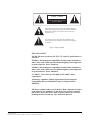
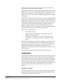
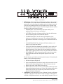
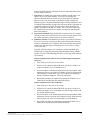
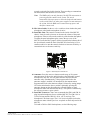
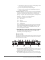
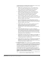
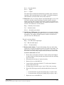
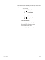
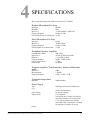
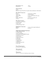
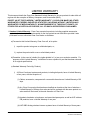
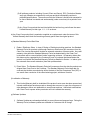
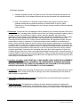
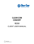
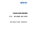
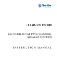
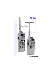
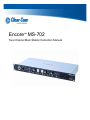
Encore™ MS-702
Two-Channel Main Station Instruction Manual
Document Reference
Encore MS-702 Two-Channel Main Station Instruction Manual
Part Number: 810342Z Rev. 4
Legal Disclaimers
Copyright © 2013 HME Clear-Com Ltd.
All rights reserved.
Clear-Com, the Clear-Com logo and Encore are registered trademarks or trademarks of HM Electronics, Inc.
The software described in this document is furnished under a license agreement and may be used only in
accordance with the terms of the agreement.
The product described in this document is distributed under licenses restricting its use, copying, distribution, and
decompilation/reverse engineering. No part of this document may be reproduced in any form by any means without
prior written authorization of Clear-Com, an HME Company.
Clear-Com Offices are located in California, USA; Cambridge, UK; Montreal, Canada; and Beijing, China. Specific
addresses and contact information can be found on Clear-Com’s corporate website:
www.clearcom.com
Clear-Com Contacts
Americas and Asia-Pacific Headquarters
California, United States
Tel: +1.510.337.6600
Email: [email protected]
Europe, Middle East, and Africa Headquarters
Cambridge, United Kingdom
Tel: +44 1223 815000
Email: [email protected]
Canada Office
Quebec, Canada
Tel: +1 (450) 653-9669
China Office
Beijing Representative Office
Beijing, P.R.China
Tel: (008610)-8528-8748
CONTENTS
IMPORTANT SAFETY INSTRUCTIONS
OPERATION . . . . . . . . . . . . . . . . . . . . . . . . . . . . . . . . . . 1-1
Introduction . . . . . . . . . . . . . . . . . . . . . . . . . . . . . . . . . . . . . . . . . . . . . . . . . 1-1
Description . . . . . . . . . . . . . . . . . . . . . . . . . . . . . . . . . . . . . . . . . . . . . . . . . . 1-1
Operation . . . . . . . . . . . . . . . . . . . . . . . . . . . . . . . . . . . . . . . . . . . . . . . . . . . 1-2
Front Panel . . . . . . . . . . . . . . . . . . . . . . . . . . . . . . . . . . . . . . . . . . . . . . . . 1-2
Rear Panel . . . . . . . . . . . . . . . . . . . . . . . . . . . . . . . . . . . . . . . . . . . . . . . . 1-7
Re-Setting Program Interrupt Options . . . . . . . . . . . . . . . . . . . . . . . . . . 1-10
INSTALLATION . . . . . . . . . . . . . . . . . . . . . . . . . . . . . . . 2-1
MAINTENANCE . . . . . . . . . . . . . . . . . . . . . . . . . . . . . . . 3-1
Introduction . . . . . . . . . . . . . . . . . . . . . . . . . . . . . . . . . . . . . . . . . . . . . . . . . 3-1
MS-702 Block Diagram . . . . . . . . . . . . . . . . . . . . . . . . . . . . . . . . . . . . . . . . 3-1
Troubleshooting Tips . . . . . . . . . . . . . . . . . . . . . . . . . . . . . . . . . . . . . . . . . . 3-2
Parts List. . . . . . . . . . . . . . . . . . . . . . . . . . . . . . . . . . . . . . . . . . . . . . . . . . . . 3-4
SPECIFICATIONS . . . . . . . . . . . . . . . . . . . . . . . . . . . . . . 4-1
LIMITED WARRANTY. . . . . . . . . . . . . . . . . . . . . . . . . . 5-1
Warranty Period . . . . . . . . . . . . . . . . . . . . . . . . . . . . . . . . . . . . . . . . . . . . . . 5-1
Technical Support. . . . . . . . . . . . . . . . . . . . . . . . . . . . . . . . . . . . . . . . . . . . . 5-1
Warranty Repairs and Returns . . . . . . . . . . . . . . . . . . . . . . . . . . . . . . . . . . . 5-2
Non-Warranty Repairs and Returns . . . . . . . . . . . . . . . . . . . . . . . . . . . . . . . 5-2
Extended Warranty . . . . . . . . . . . . . . . . . . . . . . . . . . . . . . . . . . . . . . . . . . . . 5-2
Service Contract . . . . . . . . . . . . . . . . . . . . . . . . . . . . . . . . . . . . . . . . . . . . . . 5-3
Liability . . . . . . . . . . . . . . . . . . . . . . . . . . . . . . . . . . . . . . . . . . . . . . . . . . . . 5-3
Clear-Com®
MS-702 Two-Channel Main Station Instruction Manual
i
ii
Two-Channel Main Station
IMPORTANT SAFETY
INSTRUCTIONS
Please read and follow
these instructions before
operating this product.
1.
2.
3.
4.
5.
6.
7.
8.
9.
10.
11.
12.
13.
14.
15.
Read these instructions.
Keep these instructions.
Heed all warnings.
Follow all instructions.
Do not use this apparatus near water.
Clean only with dry cloth.
Do not block any ventilation openings. Install in accordance with the
manufacturer’s instructions.
Do not install near any heat sources such as a radiators, heat registers,
stoves, or other apparatus (including amplifiers) that produces heat.
Do not defeat the safety purpose of the polarized or grounding-type plug.
A polarized plug has two blades, with one blade wider than the other. A
grounding-type plug has two blades and a third grounding prong. The
wide blade or the third prong are provided for your safety. If the provided
plug does not fit into your outlet, consult an electrician for replacement of
the obsolete outlet.
Protect the power cord from being walked on or pinched particularly at
plugs, convenience receptacles, and the point where they exit from the
apparatus.
Only use attachments/accessories specified by the manufacturer.
Use only with the cart, stand, tripod, bracket, or table specified by the
manufacturer, or sold with the apparatus. When a cart is used, use caution
when moving the cart/apparatus combination to avoid injury from
tip-over.
Unplug this apparatus during lightning storms or when unused for long
periods of time.
Refer all servicing to qualified service personnel. Servicing is required
when the apparatus has been damaged in any way, such as power-supply
cord or plug is damaged, liquid has been spilled or objects have fallen into
the apparatus, the apparatus has been exposed to rain or moisture, does
not operate normally, or has been dropped.
WARNING: To reduce the risk of fire or electric shock, do not expose
this product to rain or moisture.
Please familiarize yourself with the safety symbols in Figure 1. When you
see these symbols on this product, they warn you of the potential danger
of electric shock if the unit is used improperly. They also refer you to
important operating and maintenance instructions in the manual.
ii
Clear-Com®
MS-702 Two-Channel Main Station Instruction Manual
CAUTION
RISK OF ELECTRIC SHOCK
DO NOT OPEN
This symbol alerts you to the presence of uninsulated dangerous
voltage within the product's enclosure that might be of sufficient
magnitude to constitute a risk of electric shock. Do not open
the product's case.
This symbol informs you that important operating and maintenance instructions are included in the literature accompanying
this product.
Figure 1: Safety Symbols
EMC AND SAFETY
The MS-702 meets all relevant CE, FCC, UL, and CSA specifications set
out below:
EN55103-1 Electromagnetic compatibility. Product family standard for
audio, video, audio-visual, and entertainment lighting control apparatus
for professional use. Part 1: Emissions.
EN55103-2 Electromagnetic compatibility. Product family standard for
audio, video, audio-visual, and entertainment lighting control apparatus
for professional use. Part 2: Immunity.
UL 60065-7, CAN/CSA-C22.2 No.60065-3, IEC 60065-7 Safety
requirements.
And thereby compliance with the requirement of Electromagnetic
Compatibility Directive 2004/108/EC and Low Voltage Directive
2006/95/EC
This device complies with Part 15 of the FCC Rules. Operation is subject
to the following two conditions: (1) this device may not cause harmful
interference, and (2) this device must accept any interference received,
including interference that may cause undesired operation.
Clear-Com®
MS-702 Two-Channel Main Station Instruction Manual
iii
OPERATION
INTRODUCTION
The MS-702 two-channel
main station is a powerful,
yet user-friendly unit that
can serve as the heart of a
Clear-Com system.
Congratulations on choosing this Clear-Com product. Clear-Com was
established in 1968 and remains the market leader in providing intercoms for
entertainment, broadcast and industrial applications. The ruggedness and high
build-quality of Clear-Com products defines the industry standard. In fact,
many of our original beltpacks and main stations are still in daily use around
the world.
The MS-702 two-channel main station is a powerful, yet user-friendly unit
that can serve as the heart of a Clear-Com system. We recommend that you
read through this manual completely to better understand the functions of the
MS-702. If you encounter a situation or have a question that this manual does
not address, contact your dealer or call Clear-Com directly at the factory. Our
applications support and service people are standing by to assist you. (Refer to
Chapter 5: “Warranty” for contact information.) Thank you for selecting
Clear-Com for your communications needs.
DESCRIPTION
The Clear-Com MS-702 is a two-channel, one-rack space main station ideal
for ENG and EFP trucks, production studio consoles, theatre, live
performances, and small TV facilities. It features excellent speech
intelligibility in all noise levels and can be tailored to your needs through its
programmable options.
Selectable two-channel talking and/or listening allows the operator to
communicate on either of the intercom channels separately or on both at once.
The illuminated dual-action talk buttons provide electronic momentary or
latching capability. Monitoring can be done through the headset, the integral
speaker, or both at once. The MS-702 offers both visual and audible call
signaling to attract the attention of operators who have removed their headsets
or turned off their speakers. The remote mic kill (RMK) feature provides the
ability to turn off all open mics on remote beltpacks.
The MS-702 can control a paging speaker for studio announcements. A front
panel button activates both this function and an associated relay. A balanced
program input allows monitoring of external audio using the headset or
speaker.
This main station accepts dynamic headsets. Individual sidetone controls for
each intercom channel allow the operator to vary the level of his/her own
voice as heard in the headset and speaker. It also accepts Clear-Com
gooseneck panel microphones.
The integral speaker can be turned on or off by a convenient front panel
switch. An automatic speaker dipping circuit will lower the level of the
1-1
Clear-Com®
MS-702 Two-Channel Main Station Instruction Manual
speaker when the announce button, talk buttons or program interrupt are
activated. This feature helps minimize feedback.
The MS-702 also incorporates a dual-channel program interrupt system (IFB).
When activated, one or more stations can interrupt the program audio to either
another intercom station or a talent wearing Clear-Com’s wired or wireless
talent receivers. Clear-Com’s stand-alone IFB system can also be connected
to this station.
The MS-702 provides 30-volt DC power to operate Clear-Com beltpacks and
remote stations. This power is distributed between the two channels, and will
support up to 60 headset stations or 20 speaker stations. Clear-Com’s fail-safe
design automatically shuts down the power to a channel when a short circuit
or electronic overload is sensed on that channel. The other channel will
continue to operate normally. Once the fault condition is removed, the
MS-702’s fail-safe circuit will restore power, even under full load conditions.
LED indicators signal a short or overload on either channel.
The DC power output details are:
•
1.2A continuous output
•
2A peak output (not exceeding the 1.2A rating for more than 2
seconds per 30 second period)
•
1.75A max on any channel, with electronic current limiter (not
exceeding the 1.2A rating for more than 2 seconds per 30 second
period)
The MS-702 will operate from any AC line voltage between 90 and 240 volts
AC at 50 or 60 Hz. The MS-702 installs in a standard 19-inch (48.26 cm)
equipment rack, using only one rack space. The steel chassis and extra-thick
front panel with integral rack ears maintains legendary Clear-Com
ruggedness. Three 3-pin XLR connectors are provided for connection to each
intercom channel.
The MS-702 is compatible with all Clear-Com party-line intercoms.
OPERATION
Normal operation of the MS-702 main station requires access only to the front
panel controls. The controls located elsewhere on the unit are intended to be
set-and-forget in nature. For intercom operation, set the listen-level controls
for each channel to the desired level and press the talk buttons when talking. If
a headset is used, set the sidetone control for each channel for the desired
amount of sidetone in the earphone. If using the panel mic and speaker, set the
sidetone controls for minimum feed-through to the speaker to prevent
feedback.
FRONT PANEL
The controls, indicators, and connectors found on the MS-702 front panel are
shown in the following figure and are described the text that follows. The
numbers in the left column refer to Figure 1.
Clear-Com®
MS-702 Two-Channel Main Station Instruction Manual
2-2
18
19
5
12 14
9
7
8
6
2
8 26 10
5
1
6
7
3
11
Figure 1: Front Panel
1. Talk Buttons: Each channel has an illuminated talk button for activating
the microphone feed to that channel. Each talk button has a dual action
(momentary or latching feature) depending on how the button is pressed.
If desired, the latching function for each channel can be defeated using
the option switches on the rear panel. The following describes the various
functions of these multi-purpose buttons:
•
MOMENTARY: Press and hold the talk button while you are
speaking. Release it when you are finished.
•
LATCHING: Press the talk button quickly to latch the talk function.
Press the button again to turn off the talk function.
•
TALK INDICATION: The talk button will illuminate yellow
whenever the talk function is activated. The talk button illuminates
blue whenever the station is receiving power, but the talk function is
off.
•
CALL INDICATION: The call button will flash red when a call
signal is received on that channel.
•
CALL ON TALK: Each channel can optionally be set to send a call
signal whenever you press the talk button. This function activates
program interrupts or any other call-activated function available on
other stations. Option switches on the rear panel enable this function.
•
SPEAKER MUTE: If the front panel speaker is turned on, pressing
either talk button will reduce the speaker output level to avoid
feedback.
The talk buttons can be labeled to indicate their function. To label the talk
buttons, use the following procedure:
1. Pull the talk button straight off.
2. Insert a small flat blade screwdriver into the slot between the cap and
the body of the button and gently twist. This will remove the cap.
3. Remove the square white diffuser from the cap.
4. Insert a 1/2 in. (1.27 cm) x 1/2 in. (1.27 cm) square of thin paper with
the needed description into the cap. Follow it up with the square white
diffuser and press the cap onto the body of the button. Press the
button back into the front panel.
2. Call Buttons: Each channel has its own call button. Pressing a call button
will send a call signal on that channel. All the call lights on that channel
will flash. Call signals can also be sent while talking if required. The call
1-3
Clear-Com®
MS-702 Two-Channel Main Station Instruction Manual
button will flash while the call button is pressed, indicating the presence
of a call signal on the line.
3. Tone Alert: An audible tone alert can be enabled to sound when a call
signal is received on either channel. This can be useful when the
operator's attention has been drawn away from the MS-702 indicator
panel. Press the tone alert button to alternately enable or disable the
audible tone alert. The button illuminates blue when the audible tone alert
is enabled. When enabled, the tone alert will sound when a call button on
a beltpack or station is pressed. The tone alert will not sound if a call
signal is originated at the MS-702 station. The level can be adjusted by
the control on the rear panel (See number 4 on the rear panel diagram
later in this chapter).
5. Listen Level Controls: Each channel has a separate listen level control.
Turn these controls to set the listen level you need on each channel. Turn
the control completely counterclockwise to silence a channel.
6. Sidetone Controls: Each channel has a sidetone null control. Sidetone is
the level of your own voice that you hear while talking on the intercom.
Setting a comfortable level of sidetone will ensure that the intercom line
sounds alive and also helps you modulate your voice relative to other
voices on the line.
Typically, different sidetone null settings are needed depending upon
whether you are using the gooseneck panel microphone along with the
speaker. Use one of the following procedures to correctly set the sidetone
level controls.
Sidetone Adjustment Procedure for Gooseneck Microphone with Speaker
turned on:
1. Turn off the party-line link (A+B) switch.
2. Turn the level control for channel B all the way down. Set the level
control for channel A to a comfortable level.
3. Press the channel A talk button and speak into the microphone while
turning the sidetone null control for channel A slowly back and forth.
There should be a point where your voice (and any accompanying
acoustic feedback) disappears. This is the null point.
4. Repeat this procedure for channel B by turning the channel A level
control down and adjusting the channel B controls.
Sidetone Adjustment Procedure for Headset:
1. Turn off the party-line link (A+B) switch.
2. Turn the level control for channel B all the way down. Set the level
control for channel A to a comfortable level by having someone talk
to you from another station.
3. Press the channel A talk button and speak into the microphone while
turning the sidetone null control for channel A slowly back and forth
until you hear your voice at a comfortable level in the headset.
4. Repeat this procedure for channel B by turning the channel A level
control down and adjusting the channel B controls.
Clear-Com®
MS-702 Two-Channel Main Station Instruction Manual
2-4
7. Program ON-OFF-INTRPT Switches: The program on-off-intrpt
switches are used to manually or automatically control program audio
feed into the intercom lines. The settings are as follows:
•
ON: The channel will receive program audio when the switch is set to
on. The audio level for each channel can be adjusted with the program
level trimpots.
•
OFF: The channel will not receive program audio when the switch is
set to off.
•
INTRPT: Pressing the talk button will interrupt the program when
this switch is set to intrpt.
Note: You can set this feature so the pressing the call button for a channel,
rather than the talk button, interrupts the program audio. See the section
“Resetting Program Interrupt Options” at the end of this chapter.
8. Program Level Controls: Adjust the program-level controls to set the
program audio level heard on the intercom. There are three program-level
controls. The program level knob to the left of the speaker on-off switch
adjusts the level of program heard in the headset or panel speaker.
The program levels heard on each intercom channel line can be individually adjusted, but this is intended to be a one-time setting made when the
MS-702 is set up. This is done using the screwdriver level adjustment
trimpots adjacent to the program on-off-intrpt switches on channels A and
B. Set the sidetone null controls and the program level knob fully counterclockwise when adjusting the individual channel program-level trimpots.
After the program-level trimpots are properly adjusted, use the procedure
listed in the Sidetone Controls section on this page to set the sidetone
level.
Note:
Do not force the trimpots past their stop points. This will damage
them.
9. Party-line Link (A+B) Switch: When pressed, the party-line link (A+B)
button combines both intercom channels into one; for example, for
rehearsals. The party-line link button illuminates amber when on, and all
of the stations on the B channel will be moved onto the A intercom line.
This will allow communication between everyone on both channels at
once.
In this mode, the channel B controls and switches will be inactive. Since
the wiring for the B channel has been now added to the A channel, the
sidetone null control for channel A may require some readjustment.
10. Speaker ON/OFF Switch: The speaker on/off switch turns the front
panel speaker on or off. This switch does not affect whether the tone alert
is heard through the speaker. The speaker volume will automatically dip
whenever the panel or headset microphone is on.
11. Remote Mic Kill Switch: The remote mic kill (RMK) switch will turn off
the talk function of every beltpack on channels A and B. If the talk
functions of a large number of beltpacks have inadvertently been left
activated, incidental noise and talking can make it difficult or impossible
to communicate on the party-line intercom. The RMK switch can be
1-5
Clear-Com®
MS-702 Two-Channel Main Station Instruction Manual
pressed to quiet the line in this situation. Those needing to communicate
can then set their talk functions to on as needed.
Note:
The RMK switch can only function if the MS-702 main station is
powering all of the stations in the system. The switch
momentarily interrupts power to the other beltpacks and stations
in the system. If there are other power supplies or main stations in
the system, then the RMK switch cannot interrupt power and
therefore cannot work.
12. Mic Select Switch: Set the mic select switch to select whether the panel
microphone or the headset microphone is active.
13. Panel Mic Gain: This control is located on the inside of the MS-702
chassis. It may be used to increase or decrease the volume of the panel
microphone. It has no effect on the sensitivity of the headset microphone.
To adjust the panel microphone gain, remove the top cover of the
MS-702. Locate the R161 jumper, which is located on the leftmost side of
the circuit board, toward the front of the MS-702 when facing it. Use a
small screwdriver to turn the control clockwise to increase sensitivity or
counterclockwise to decrease sensitivity.
R161
Gain Adjust
Figure 2: Gain Adjust Control R161
14. Announce: Press the announce button to make stage or PA system
announcements. It directs the audio from the selected headset or panel
microphone to the annc out rear panel connector and activates the
announce relay. Simultaneously, if the program audio feed to the
announce output is enabled, it is interrupted by the announcement.
Program audio feed to the announce output is selected by setting jumper
JP2 on the main board to the on position. Optionally, pressing the
announce button can also disconnect the selected headset or panel
microphone audio from the intercom line(s). This option is controlled by
the interrupt announce option switch.
18. Panel Mic Connector: Clear-Com recommends the GM-9 and GM-18
plug-in panel microphones for use with the MS-702. The GM-9 is 9 in.
(22.86 cm) long and the GM-18 is 18 in. (45.72 cm) long. The
microphone is an electret type. The 1/4 in. (0.64 cm) phone jack on the
microphone mates with the panel mic receptacle on the front panel of the
MS-702.
To install a GM-9 or GM-18 microphone, use the following steps:
Clear-Com®
MS-702 Two-Channel Main Station Instruction Manual
2-6
1. Check and unscrew the set screw in the mic mounting flange to make
sure it is clear of the threads in the bushing.
2. Screw the microphone into the bushing hand tight.
3. Turn the set screw on top of the mic mounting flange clockwise to
lock the microphone in place.
19. Headset Connector: The headset connector is located on the front panel.
All Clear-Com headsets are recommended for use with the MS-702. The
following is a description of the characteristics of a suitable headset:
Mic Type --- Dynamic; 150 to 250 ohms impedance; -55 dB output level
Headphone --- Dynamic; 50 to 2000 ohms impedance
The wiring of the headset is to be as follows:
Pin 1 --- Mic common
Pin 2 --- Mic hot
Pin 3 --- Headphone common
Pin 4 --- Headphone hot
The mic and headphone wiring in the headset cord must be individually
shielded. Do not connect pins #1 and #3 together. Headset extension
cords or headset “Y” cables are not recommended because they will
increase crosstalk between channels.
26. Short Lights: There is one red light for channel A and one for channel B.
These lights illuminate when the MS-702 senses a short or overload on
the associated channel. When the fault is removed, the MS-702 will
automatically reset and the light will go out.
REAR PANEL
The controls and connectors found on the MS-702 rear panel are shown in the
following figure and briefly described by the text that follows. The numbers
in the left column refer to Figure 3.
21
20
21
21
21
21
22
21
23
24
25
MS-702
17
16
16
4
15
Figure 3: Rear Panel
4. Tone Alert Volume Control: This control adjusts the volume of the tone
alert sound. This is normally adjusted when the system is set up and there
should be no need to adjust it in normal operation.
15. Option Switches: Eight option switches are provided on the rear panel.
They should be configured when the system is set up, but are not changed
1-7
Clear-Com®
MS-702 Two-Channel Main Station Instruction Manual
in normal operation. The default position of the switches is in the off (up)
position. The function of each switch is as follows:
1. MOM TALK A: Setting the momentary talk A switch to the on
position will disable the latching function of the channel A talk
button. In this mode, the talk button must always be held in
continuously while the operator is talking on channel A.
2. MOM TALK B: Setting the momentary talk B switch to the on
position will disable the latching function of the channel B talk
button. In this mode, the talk button must always be held in
continuously while the operator is talking on channel B.
3. CALL ON TALK A: If the call on talk A switch is set to the on
position, a call signal will be placed on channel A whenever the talk
function is activated. This can be used to activate any call-activated
functions available on other stations.
4. CALL ON TALK B: If the call on talk B switch is set to the on
position, a call signal will be placed on channel B whenever the talk
function is activated. This can be used to activate any call-activated
functions available on other stations.
5. INTRPT ANNC: If the interrupt announce switch is set to the on
position, pressing the announce button will disconnect the
microphone from the intercom line(s). This will allow
announcements to be made without being heard over the intercom
channels.
6. INTRPT EXT IFB: When the hot mic output is connected to
Clear-Com’s IFB system and the interrupt external IFB switch is set
to the on position, pressing a key on the IFB system will disconnect
the selected headset or panel microphone from the intercom line(s).
This allows the MS-702 microphone to be used to cue talent without
affecting intercom line communication.
7. LONG LINE A: If a long cable run on channel A is unavoidable and
approaches 1,000 ft. (305 m) or more, set the long line A option
switch to the on position. The ability to set a sidetone null on channel
A depends upon properly setting this switch.
8. LONG LINE B: If a long cable run on channel B is unavoidable and
approaches 1,000 ft. (305 m) or more, set the long line B option
switch to the on position. The ability to set a sidetone null on channel
B depends upon properly setting this switch.
16. Termination Switches: These switches provide switchable terminations
for channels A and B. In most systems, both terminations on the MS-702
should be in the on position (default setting). The fundamental concept of
the Clear-Com party-line intercom is that all channels are terminated in
one location, preferably at a main station or power supply. The
termination switches on the MS-702 rear panel should be set to the off
position only if the channel is terminated by another main station or
power supply in the system. If there are no other main stations, power
supplies, or other terminations on the line, set the rear panel switches
labeled term A and term B to the on position.
Note:
All intercom lines must be terminated only once, whether they are
used or not. Never “double-terminate” a line.
Clear-Com®
MS-702 Two-Channel Main Station Instruction Manual
2-8
17. Power Switch: The power switch can be used to turn AC power to the
MS-702 on and off. When in the on position, the front-panel talk buttons
illuminate blue.
20. AC Power Connection: An IEC type 320 connector is provided to
interface to the appropriate AC power cord to be used. Voltages from 90
to 240 VAC at 50 or 60 Hz are acceptable. The MS-702 will automatically
adjust for the power applied, so there are no manual switches to set power
line voltage or frequency.
21. Intercom Line Connection: The MS-702 contains three 3-pin male XLR
connectors for each intercom line. These connectors are wired in parallel.
Any single-channel station or channel of a multi-channel station
connected on a line plugged into channel A of the MS-702 will be “party
lined” with all the other stations on that channel. In a multi-channel
system, the goal is to assign specific people to the correct group (i.e. the
other people they need to be in contact with the most). This is particularly
important when the party-line users are on a single-channel beltpack or
station, less so if they are on multi-channel stations. The pinout of the
intercom connectors is as follows:
Pin 1 --- Ground (shield)
Pin 2 --- Power (+30 VDC)
Pin 3 --- Audio
22. Program Input: A 3-pin XLR female connector provides the main
program input to the station. Program can be fed to the headphone or
speaker as well as to either or both of the intercom channels. The level to
the speaker or headphone is controlled by the program level control. The
program on-off-intrpt switches control whether each intercom channel
receives program audio. The program audio levels on each intercom
channel can be adjusted using the individual program-level trimpots. The
program input accepts a balanced or unbalanced line-level audio signal
from -20 dBv to +10 dBv. An option is to feed program audio to the
announce output. This is selected by setting jumper JP2 on the main
board to the on position. When this option is selected, a 0 dBv signal on
the program input will produce a 0dBv signal on the announce output.
The pinout of the program input connector is as follows:
Pin 1 --- Ground (shield)
Pin 2 --- + Signal
Pin 3 --- - Signal
23. Announce Out: A 3-pin XLR male connector is provided as a feed to a
studio PA amplifier. Pressing the announce button on the front panel
places the audio from the selected headset or panel microphone on the
annc out rear-panel connector. Optionally, pressing the announce button
can also disconnect the selected headset or panel microphone from the
intercom line(s). This option is controlled by the interrupt announce
option switch. Simultaneously, if the program audio feed to the announce
output is enabled, it is interrupted by the announcement. Program audio
feed to the announce output is selected by setting jumper JP2 on the main
board to the on position. The pinout of the announce out connector is as
follows:
1-9
Clear-Com®
MS-702 Two-Channel Main Station Instruction Manual
Pin 1 --- Ground (shield)
Pin 2 --- - Signal
Pin 3 --- + Signal
The audio output is balanced and transformer isolated. It has a 600 ohm
impedance and a nominal output level of 0 dBV. A shielded twisted pair
cable should be used in the cable wired to this connector.
24. Relay Out: A dry set of relay contacts is provided through a 1/4-in. (0.64
cm) jack to activate external switching as needed when the announce
button is pressed. These contacts can be used to control an external device
such as a PA amplifier to another room. The contacts are rated for 2.0 A at
24 VDC. The contacts are wired as follows:
Ring --- Normally closed contact
Tip --- Common contact
Sleeve --- Normally open contact
25. Hot Mic Out / IFB System: This connection is a 1/4-in. (0.64 cm) phone
jack. It provides a 0 dBV output signal from the selected headset or panel
microphone. This output is intended interface with the external line-in
jack on Clear-Com’s IFB System.
The jack is wired as follows:
Ring --- Ext. IFB control signal input
Tip --- Hot mic audio output
Sleeve --- Ground (shield)
27. Headset Audio Limiter: To protect the hearing of the user, the headset
audio limiter restricts the maximum audio level heard in the headset. The
MS-702 unit is shipped with the headset audio limiter on. You can turn
this feature on or off by using a jumper located on the main circuit board.
To turn the audio limiter on or off:
1. Please observe anti-static procedures. Circuit cards can be damaged
by static electricity. Please ground yourself and tools before touching
any circuit cards.
2. Disconnect the unit from AC mains electricity.
3. Remove the cover of the RM-702.
4. Locate the three-pin jumper labeled “J3” on the center frontmost
portion of the circuit card.
5. A jumper plug is located over pins 2 and 3. This is the on setting.
6. Do one the following to turn the audio headset limiter feature on or
off:
•
To turn the feature on, place the jumper plug over pins 2 and 3.
•
To turn the feature off, place the jumper plug over pins 1 and 2.
7. Replace the cover of the RM-702.
Clear-Com®
MS-702 Two-Channel Main Station Instruction Manual
2-10
8. Connect the unit to AC mains electricity.
RE-SETTING PROGRAM INTERRUPT
OPTIONS
When you set one of the front-panel Program ON-OFF-INTRPT switches to
the INTRPT position, any talk signal activated on that channel interrupts the
program audio during the talk signal.
You can change this option so that activating a call signal, rather than a talk
signal, interrupts the program audio for the duration of the signal. You do this
by re-setting an internal jumper on the station’s internal circuit board.
To re-set the program interrupt option:
1. Please observe anti-static procedures. Static electricity can damage a
circuit card. Please ground yourself and tools before touching the circuit
card.
2. Remove the cover of the MS-702 by removing the eight Phillips screws.
3. On the main circuit board, locate one of the following:
•
For channel A: The JP5 three-pin jumper, located in the center of the
circuit board.
•
For channel B: The JP6 three-pin jumper, located in the center of the
circuit board.
4. A jumper plug covers two of the three pins on each jumper. To change the
program-interrupt option on your station, do one of the following:
1-11
•
For channel A: Move the jumper plug so that it covers pins 2 and 3.
This causes call signal activation to interrupt the program audio
•
For channel B: Move the jumper plug so that it covers pins 2 and 3.
This causes call signal activation to interrupt the program audio.
Clear-Com®
MS-702 Two-Channel Main Station Instruction Manual
In the default position, the jumper plug covers pins 1 and 2, which causes
talk signal activation, rather than call signal activation, to interrupt the
program audio.
JP5, for channel A
1
2
3
Talk signals
interrupt
program audio
JP6, for channel B
1
Call signals
2
3
interrupt
program audio
FOR EITHER CHANNEL:
To interrupt program audio during talk signals,
place jumper plug over pins 1 and 2.
To interrupt program audio during call signals,
place jumper plug over pins 2 and 3.
Figure 4: Changing Program Interrupt Options
Clear-Com®
MS-702 Two-Channel Main Station Instruction Manual
2-12
INSTALLATION
1. Unpack the unit and inspect for any damage that may have occurred in
shipping.
2. Connect the proper AC mains cable.
3. Install the MS-702.
Note: For additional information, refer to the Clear-Com System
Installation Manual.
4. Connect the AC to the mains circuit.
Note: Information on the mains power requirement is given on the
underside of the unit.
5.
6.
7.
8.
Connect the intercom lines.
Set the two termination switches on the rear panel to on.
Set the option switches to the default (up) position.
Switch power on.
The blue talk button lights should be on and the two red short lights
should be off.
9. Set listen levels and sidetones.
Refer to the listen level and sidetone setting topics in the Operation section of this manual.
10. The intercom system should now be operating properly.
Read the rest of this manual for further information.
2-1
Clear-Com®
MS-702 Two-Channel Main Station Instruction Manual
Clear-Com®
MS-702 Two-Channel Main Station Instruction Manual
2-2
MAINTENANCE
INTRODUCTION
This chapter provides maintenance information, including a block diagram and troubleshooting tips.
Caution:These servicing instructions are for use by qualified personnel only. To reduce the risk of electrical shock,
do not perform any servicing other than that contained in the operating instructions unless you are qualified
to do so.
MS-702 BLOCK DIAGRAM
The following is a block diagram of the MS-702:
MS-702
Headset
Mic
Headset
Main
Pgm
XLR4
Mic
Limiter
Panel
Mic
Jack
XLR4
Program
Level
Line
Length
Sidetone
Null
Headset
Limiter
Panel Mic
Gain
Listen
A
Main
Pgm
Spkr
On/Off
Intercom
Line A
Program
Level A
Mute
Line
Length
Sidetone
Null
Alert Tone
Level
Listen
B
Main
Pgm
Intercom
Line B
Program
Level B
Main
Pgm
3
Main
Pgm
2
3
+30VDC
IEC Power
Inlet
Switching
Power
Supply
+30VDC
SA
Output
2
Main
Pgm
On/Off
Alert Tone
Generator
Power
Control uP
Hot Mic /
IFB Out
Power B
2
Channel B
3
1 XLRs (3)
+30VDC
+5VDC
Intercom A
Lines B
Option Switches
Annc Rly
Control
To All
Switches
Front Panel
Switches,
Buttons, &
Indicators
Call Alert
Tone
System Logic
RMK
Power A
2
Channel A
3
1 XLRs (3)
Intercom
Line Linking
&
Termination
Link
Call
Signal
Send &
Receive
A Intercom
B Lines
Figure 3-6: Block diagram of the MS-702
Clear-Com®
MS-702 Two-Channel Main Station Instruction Manual
3-1
TROUBLESHOOTING TIPS
SYMPTOM
System does not operate. Blue
talk buttons do not illuminate
and short lights do not
illuminate.
CAUSE
SOLUTION
No AC power to the MS-702.
Make sure the power switch on the
rear panel is turned on. Check the
AC connection and cable. Plug into a
dependable AC source.
The MS-702 has an internal power
supply failure.
Unit requires servicing.
System does not operate when
power switch is turned on. Blue
talk lights and red short lights
wink.
Direct short on the intercom channel
indicated by the red short light.
Remove the intercom line cables one
at a time from that channel until the
faulty line is located. Once the short
is removed, the MS-702 will reset
automatically and power will come
back up. Check for shorts between
pins #1 and #2 or improper cable
wiring.
Red short light is illuminated.
Short or overload on that channel
due to a shorted or miswired cable.
Remove the intercom line cables one
at a time from the system until the
faulty line is located. (The red short
light will then turn off.) Check for
shorts between pins #1 and #2 or
improper cable wiring. Once the
short is removed, the MS-702 will
reset automatically and power will
come back up.
Defective remote station.
Check the remote station and replace
if necessary.
System is overloaded.
Remove the intercom line cables one
at a time from the system to help
determine where the excess current
requirements lie. Re-evaluate the
system current needs.
Short in multipair cable.
Remove the intercom line cables one
at a time from system until the faulty
line is located. Check for shorts
between pins #1 and #2 or improper
cable wiring.
Inductive pickup caused by close
proximity of this main station or
connected remote stations to power
lines or transformers.
Relocate the offending unit.
Both red short lights are
illuminated.
Problem: Hum or buzz in
system.
3-2
Clear-Com®
MS-702 Two-Channel Main Station Instruction Manual
SYMPTOM
CAUSE
10 Ohm chassis ground resistor is
open.
SOLUTION
Check the DC resistance for
10 Ohms between the chassis and
pin #1 of any intercom connector.
If this condition occurs, it is
because the system ground came
into contact with something that
was “HOT” with respect to the
power supply earth ground.
Carefully check the system ground
and AC distribution in the area.
Warning: This is a potentially
dangerous situation. A shock hazard
may exist between a remote station
headset and ground.
System feedback (Acoustical)
Listen level control at this station or
a remote station is set too high.
Adjust.
Sidetone null control at this station
or a remote station is not adjusted
correctly.
Adjust. Refer to the procedure in the
front panel section of this manual.
Channel unterminated.
Set the MS-702 termination switch
for that channel to the on position.
A headset extension cord was used.
Headset extension cords are not
recommended.
High DC resistance in ground return.
Use heavier cable; add additional
conductor(s) to ground return.
Multi-channel cable pairs are not
individually shielded.
Replace cable with individually
shielded pairs.
Headset cables are not wired
properly or shielded properly.
Correct wiring. Use headsets with
properly shielded wiring.
Program signal sounds
distorted.
Overload of program input circuit.
Reduce program input level or
reduce the gain of the program signal
at the source, such as an audio mixer.
Call signals do not function.
Excessive DC loading of intercom
line.
Remove any audio transformers or
other equipment that may be
connected across the intercom line.
If equipment other than Clear-Com
intercom equipment must be
connected to the intercom line,
please contact Clear-Com
application or service personnel for
advice.
Excessive crosstalk
Clear-Com®
MS-702 Two-Channel Main Station Instruction Manual
3-3
SYMPTOM
CAUSE
SOLUTION
Far too many terminations on the
intercom line.
Check all main stations and power
supplies to make sure each intercom
channel is terminated at only one
point.
Table 3-1: Troubleshooting Tips
3-4
Clear-Com®
MS-702 Two-Channel Main Station Instruction Manual
SPECIFICATIONS
dBv is an absolute measurement. 0 dBv is referenced to 0.775 V RMS.
Headset Microphone Pre-Amp
Input Type:
Impedance:
Input Level:
Frequency Response
Gain from headset mic to intercom line:
Panel Microphone Pre-Amp
Input Type:
Input Level:
Frequency Response
Gain from panel mic to intercom line:
Dynamic
1KΩ
-55 dBV nominal; -10 dBV max.
200 Hz to 15 kHz
+41 dB
Electret
-45 dBV nominal
450 Hz to 12 kHz
+31 dB
Headphone/Speaker Amplifier
Load Impedance Range:
Output Level:
Distortion:
Frequency Response:
Gain from intercom line:
Power Output:
50Ω - 2 KΩ
At least +20 dBV across 600Ω
< 0.2% THD @ 1 KHz
200 Hz - 18 KHz, ±2 dB
+37 dB
110 dB SPL
Program Amplifier (Transformerless, balanced differential
input)
Input Level:
Input Impedance:
Frequency Response:
Termination Impedance
Impedance:
Power Supply
Type:
reset
Output Voltage:
Output Current:
0 dBV
> 100 KΩ
150 Hz - 18 KHz, ±2 dB
200Ω, switchable
Switching, with overcurrent limiting and
circuitry for each channel
30 volts DC regulated
1.2A Continuous
2A Peak (Do not exceed the 1.2A rating for
more than 2 seconds per 30 second period)
1.75A max any channel, with electronic
current limiter (Do not exceed the 1.2A rating
for more than 2 seconds per 30 second
period)
Clear-Com®
MS-702 Two-Channel Main Station Instruction Manual
4-1
Short Circuit Reset Time:
Hum and Noise:
< 15 s
< -80 dBv
Station Capacity
Capacity:
Maximum of 60 headset stations or 20 speaker stations, distributed over both channels
Rear Panel Connectors
Intercom:
Announce Out:
Announce Relay:
Program:
Hot Mic / IFB Interface:
AC Power:
(6) XLR-3M (3 per channel)
(1) XLR-3M (audio)
(1) 1/4 in. (0.64 cm) phone jack (relay)
(1) XLR-3F
(1) 1/4 in. (0.64 cm) phone jack
IEC 320 connector
Rear Panel Controls
(2) Termination On-Off switches
(8) Option switches
(1) Power switch
(1) Tone alert volume control
Front Panel Connectors
Panel Mic:
Headset:
(1) 1/4 in. (0.64 cm) panel mounting jack
(1) XLR-5F
Front Panel Controls & Indicators
(1) Panel / headset mic switch
(1) Announce button
(1) Party line link button
(2) Program ON-OFF-INTERRUPT switches
(3) Program level controls
(2) Listen controls
(2) Sidetone null controls
(2) Talk buttons
(2) Call buttons
(1) Tone alert button
(1) RMK button
(1) Speaker ON-OFF switch
(2) Short LEDs
Power Requirements
90 - 240 VAC, 50 - 60 Hz, 60 VA
Environmental
32 - 122o F (0 - 50o C)
Dimensions
19 in. W x 1.75 in. H x 6.5 in. D (483 mm x 44 mm x 165 mm)
4-2
Clear-Com®
MS-702 Two-Channel Main Station Instruction Manual
Weight
5.0 lbs. (2.75 kg)
Notice About Specifications
While Clear-Com makes every attempt to maintain the accuracy of the
information contained in its product manuals, that information is subject to
change without notice. Performance specifications included in this manual
are design-center specifications and are included for customer guidance and
to facilitate system installation. Actual operating performance may vary.
Clear-Com®
MS-702 Two-Channel Main Station Instruction Manual
4-3
4-4
Clear-Com®
MS-702 Two-Channel Main Station Instruction Manual
LIMITED WARRANTY
This document details the Clear-Com Standard Limited Warranty for all new products for sale within all
regions with the exception of Military, Aerospace, and Government (MAG).
EXCEPT AS SET FORTH HEREIN ("LIMITED WARRANTY"), CLEAR-COM MAKES NO OTHER
WARRANTIES, EXPRESS, IMPLIED OR STATUTORY, INCLUDING WITHOUT LIMITATION ANY
WARRANTIES OF MERCHANTABILITY, NONINFRINGEMENT OF THIRD PARTY RIGHTS, OR
FITNESS FOR A PARTICULAR PURPOSE, ALL OF WHICH ARE EXPRESSLY DISCLAIMED.
1. Standard Limited Warranty. Clear-Com warrants its products, including supplied accessories,
against defects in material or workmanship for the time periods as set forth below provided it was
purchased from an authorized Clear-Com dealer or distributor.
a) Pursuant to this Limited Warranty, Clear-Com will, at its option:
i)
repair the product using new or refurbished parts, or;
ii) replace the product with a new or refurbished product.
b) Remedies: In the event of a defect, the rights detailed in 1 (a) are your exclusive remedies. For
purposes of this Limited Warranty, "refurbished" means a product or part that has been returned
to its original specifications.
c) Standard Warranty Period (by Product):
i)
All Clear-Com brand systems and products, including belt packs, have a Limited Warranty
of two years, with the exception of;
(1) Cables, accessories, components & consumable items have a Limited Warranty of 90
days.
(2) Any Clear-Com product that has been classified as obsolete at the time of sale has a
Limited Warranty of 90 days from sales and will be replaced with the same product or a
sales credit will be issued, at the sole discretion of Clear-Com.
(3) Headsets, handsets, microphones, and associated spare parts, as well as UHF wireless
IFB products, have a Limited Warranty of one year.
(4) UHF WBS Analog wireless intercom systems have a Limited Warranty of three years.
i
Clear-Com®
Standard Limited Warranty
(5) All software products, including Concert (Client and Server), ECS, Production Maestro
and Logic Maestro are warranted for one year and shall substantially conform to
published specifications. The media on which the Software is furnished is warranted to
be free of defects in material and workmanship (under normal use) for a period of one
year.
(6) Any Clear-Com products that are listed within the last time buy period have the same
Limited Warranty for their type 1.i 1 - 1.i.5 as above.
d) Any Clear-Com product that is repaired or supplied as a replacement under the terms of this
Limited Warranty shall inherit the remaining warranty period from the original product.
e) Standard Warranty Period Start Date
i)
Dealer / Distributor Sales: In view of Dealer or Distributor stocking practices, the Standard
Warranty Period for products sold through Dealers or Distributors will commence from the
Clear-Com invoice date and will include an automatic extension of three months. Any valid
warranty claim within the Standard Warranty Period as determined by the Clear-Com
invoice date will be covered without further supporting evidence. All warranty claims after
this date must be supported by the Customer's proof of purchase that demonstrates the
product is still within the Standard Warranty Period (as detailed in Section 1.c.i above, plus
the automatic three month extension) from their purchase date.
ii) Direct Sales: The Standard Warranty Period will commence from the date the product was
shipped from Clear-Com to the Customer. The Standard Warranty Period start date for
contracts that include commissioning will be the date of the Site Acceptance Test (SAT) or
one month from conclusion of the commissioning project, whichever is earlier.
f) Invalidation of Warranty
i)
This Limited Warranty shall be invalidated if the product's outer case has been opened and
internal modifications have been made or damage has occurred, or upon the occurrence of
other damage or failure not attributable to normal wear and tear. Authorized modifications
with Clear-Com's express written permission will not invalidate the warranty.
g) Software Updates
i)
Software Updates are released periodically to correct discovered program bugs. During the
Warranty Period, software updates are available to Customers free of charge.
Clear-Com®
Standard Limited Warranty
ii
h) Software Upgrades
i)
Software Upgrades include new Features and/or Functional Enhancements and are not
included as part of the Standard Warranty but may be purchased at the published rates.
ii) Note: In the absence of a Software Update containing a program correction and no
available workaround to mitigate the problem, at the discretion of Service, Sales,
Engineering, or Product Management, the Customer may be provided a Software Upgrade
under warranty.
2. Exclusions. Services do not cover damage or failure caused by any occurrence beyond Clear-Com's
reasonable control, including without limitation acts of God, fire, flooding, earthquake, lightning, failure
of electric power or air conditioning, neglect, misuse, improper operation, war, government
regulations, supply shortages, riots, sabotage, terrorism, unauthorized modifications or repair, strikes,
labor disputes or any product failure that Clear-Com determines is not a result of failure in the
Services provided by Clear-Com. Further Services excluded from this Agreement include: services
required due to errors or omissions in Customer purchase orders; installation or maintenance of
wiring, circuits, electrical conduits or devices external to the products; replacement or reconditioning
of products which, in Clear-Com's opinion cannot be reliably maintained or properly serviced due to
excessive wear or deterioration; Customer's failure to maintain the installation site in accordance with
the environmental specifications of the products; or service on products removed from the location
originally specified by Customer and/or reinstalled without the prior written approval of Clear-Com.
Customer will pay Clear-Com's then current published charges to restore such Covered Products to a
condition eligible for further service under this Agreement. Clear-Com shall be excused from and shall
not be liable for any failure or delay in performance under this Agreement due to the foregoing or any
causes beyond its reasonable control.
3. Limitation of Liability. IN NO EVENT WILL CLEAR-COM BE LIABLE UNDER THIS AGREEMENT
FOR ANY INDIRECT, SPECIAL, INCIDENTAL OR CONSEQUENTIAL DAMAGES (INCLUDING
WITHOUT LIMITATION LOST PROFITS), REGARDLESS OF THE FORM OF ACTION, EVEN IF
ADVISED IN ADVANCE OF THE POSSIBILITY OF SUCH DAMAGES.
4. Assignment. Neither party may assign this Agreement or any portion thereof without the prior written
consent of the other, except in the event of a merger, sale of all or substantially all of the assets or
other corporate reorganization.
5. Ownership of replaced parts or product. All replaced parts or products become the property of
Clear-Com.
6. Entire Agreement. This Agreement constitutes the entire agreement between the parties with
respect to the subject matter hereof, and supersedes all prior or contemporaneous proposals, oral or
written, and all other communications between them relating to the subject matter of this Agreement.
iii
Clear-Com®
Standard Limited Warranty
Clear-Com®
Standard Limited Warranty
iv