1
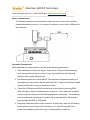
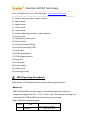
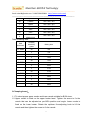
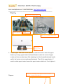
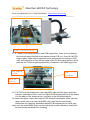
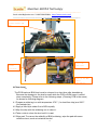
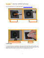
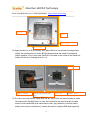
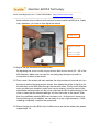
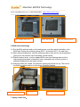
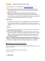
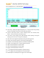
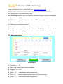
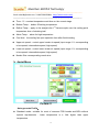
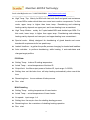
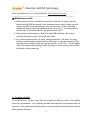
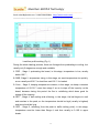
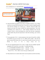
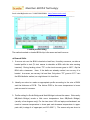
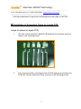
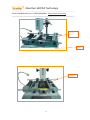
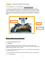
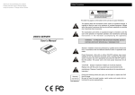
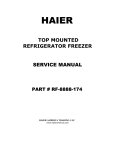
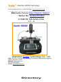
Shenzhen SCOTLE Technology ----------------------------------------------------------------------Email:[email protected] Tel:8675589378931 http://www.scotle.com/ ------------------------------------------------------------------------------------------------ BGA Hot Air BGA Rework Station (Model No: Scotle-HR360) USER MANUAL V1.0 Shenzhen Scotle Technology Co., Ltd. ADD: First Floor, A# Dormitory, Nankeng First Industry Park,Bantian,Longgang District, Shenzhen, China Website: www.scotle.com Tel: 8675589378931 E-mail: [email protected] Directory Shenzhen SCOTLE Technology ----------------------------------------------------------------------Email:[email protected] Tel:8675589378931 http://www.scotle.com/ ------------------------------------------------------------------------------------------------ Ⅰ.Instructions on Installation and Operating precautions ........................................................... 2 Ⅱ.Introduction of Rework Station Scotle-HR360 Ⅲ. BGA Operating Procedures ................................................................................................ 5 ⒈Bakeout:........................................................................................................................ 5 2.Clamping board: ............................................................................................................ 6 3. Remove/Desolder: ........................................................................................................ 9 4.Clean Land: ................................................................................................................. 10 5. BGA Reball: .................................................................................................................. 11 6. BGA reball soldering: .................................................................................................. 14 7. Apply solder flux:......................................................................................................... 14 8. Mounting:.................................................................................................................... 15 9. Solder: ........................................................................................................................ 15 Ⅳ.Introduction of Touch Screen Control ................................................................................... 15 V. Creating a Profile Ⅵ. Installation of Supporting Clamp for Laptop PCB................................................................. 25 Ⅶ. Alarm Malfunction and Solutions ......................................................................................... 27 Ⅷ. Maintenance Ⅸ. Scotle-HR360 Technical Parameters Ⅰ.Instructions on Installation and Operating precautions Assembling Site To ensure security and avoid possible damages, the Rework Station should be located where it complies with following conditions: ◆ Away from inflammables. ◆ Free from splashing of water or other liquids. ◆ Free from the direct airflow impact from air conditioner, heater or ventilator. ◆ With good ventilation, dry and free from excessive dust. ◆ Stable and flat location that is free from vibration and shock. Power Supply Power and voltage should meet the below requirements. ◆ Use the power supply with little voltage fluctuation Voltage fluctuation: AC220V±10%。 Frequency fluctuation: 50/60Hz±0.3%。 Shenzhen SCOTLE Technology ----------------------------------------------------------------------Email:[email protected] Tel:8675589378931 http://www.scotle.com/ -----------------------------------------------------------------------------------------------Space requirements: To facilitate operation and maintenance when we have to move the machine forward/backward and turn it, it is required to reserve a room that is >300mm far from the back. Operation Precautions: While operating the rework station, pls follow the following precautions: 1. After switching on the power supply, firstly check if there is airflow blowing from the upper/lower hot air nozzle. If not, it is prohibited to start heating. Otherwise the heater will get burnt. 2. Set different profiles for various BGA. The maximum temperature setti ng of any segment of the profile shall be less than 300℃. Refer to the BGA tin bead welding profile while using the lead-free rework. 3. Check the PCB land and BGA tin bead one by one before mounting BGA. After mounting, check the appearance one by one. If a ny abnormal symptom occurs, stop mounting and check the temperature immediately. The soldering can be continuously performed only after the proper adjusting. Otherwise it may damage the BGA or PCB plate. 4. Regularly clean the surface of the machine. In particular, keep the IR heating board surface clean. Prevent the dirt drops on it. The dirt may affect the proper heat radiation and result in poor welding quality as well as 2 Shenzhen SCOTLE Technology ----------------------------------------------------------------------Email:[email protected] Tel:8675589378931 http://www.scotle.com/ -----------------------------------------------------------------------------------------------considerably reduce the lifetime of the IR heater. 5. Untrained operator can‟t change a ny set parameters. 6. Avoid electric fans or other equipments blowing toward to the rework station while it is working, or it may cause the heater‟s abnormal temperature rise, and the work piece will get burnt. 7. While it is working, don‟t put any stuff on the heating area. Otherwise the stuff will get burnt. The PCB should be put on the supporting frame. 8. It is prohibited to touch the heating area to avoid burn while working. 9. While working, keep the rework station away from the flammable sprays, liquid or gas. 10. Don‟t remove the front panel or cover of the electric cabinet that is with HV (high voltage) components in that may cause electric shock. 11. In case the metal or liquid falls into the station while it‟s working. Shut off power and pull out the plug. Clean away all the dirt after the machine cools down. It will give out bad smell if there is dirt when it restarts. Note: Never clean the IR heater (heating board) with liquid. Use fine sand paper to rub away the stubborn dirt on the IR heating board. We will be irresponsible for replacing the heater for free for the previous mentioned reason. Ⅱ. Introduction of Rework Station Scotle-HR360 BGA Rework Station Scotle-HR360 made by Scotle has 3 heaters (Upper Heater, Lower Heater and Bottom IR Heater). The upper and lower heaters heat directly towards BGA part to ensure BGA gets enough heat to reach the melting point to come to good welding quality. The bottom heating zone is large area IR heating board for preheating the whole PCB board to insure even heating and prevent the PCB get deformed. Scotle-HR360 Diagram: 3 Shenzhen SCOTLE Technology ----------------------------------------------------------------------1 2 3 Email:[email protected] Tel:8675589378931 http://www.scotle.com/ ------------------------------------------------------------------------------------------------ 13 4 14 5 6 7 8 9 10 22 21 15 16 17 18 11 19 12 20 Parts name: 1) Knob for fine-adjusting the height of the upper heater 2) Knob for locking the upper heater from moving forward/backward 3) Handle for locking upper heater from rotating 4 Shenzhen SCOTLE Technology ----------------------------------------------------------------------Email:[email protected] Tel:8675589378931 http://www.scotle.com/ -----------------------------------------------------------------------------------------------4) Knob for adjusting upper heater up/down 5) Upper heater 6) Upper nozzle 7) Lower nozzle 8) Lower heater 9) Knob for adjusting the lower heater up/down 10) Vacuum pen 11) Temperature sensor joint 12) Touch screen 13) Knob for locking PCB jig 14) Knob for positioning PCB 15) Laser light 16) PCB supporting bar 17) PCB clamping device 18) Spot light 19) Cooling fan 20) Power switch 21) Lamp on/off 22) Laser light on/off Ⅲ. BGA Operating Procedures BGA rework on PCB should comply with the following procedures: ⒈Bakeout: Both PCB and BGA must be baked in a constant temperature oven at a temperature range from 80℃~100℃ for 8h~20h. The purpose of baking is to dehumidify the PCB and BGA in case blowout during rework. Table 1 Moisture sensibility grade: Grade 1 Time Timeless Context Saving (RH: relative humidity) ≤30℃/85% RH 5 Shenzhen SCOTLE Technology ----------------------------------------------------------------------Email:[email protected] Tel:8675589378931 http://www.scotle.com/ -----------------------------------------------------------------------------------------------2 1 year ≤30℃/60% RH 2a 4 weeks ≤30℃/60% RH 3 168hs ≤30℃/60% RH 4 72hs ≤30℃/60% RH 5 48hs ≤30℃/60% RH 5a 24hs ≤30℃/60% RH 6 Refer to the labeled time ≤30℃/60% RH Table 2 Baking time: Seal thickness Humidity sensitivity ≤1.4MM ≤2.0MM ≤4.0MM Baking time grade 2a 4hs 3 7hs 4 9hs 5 10hs 5a 14hs 2a 18hs 3 24hs 3 31hs 5a 37hs 2a 48hs 3 48hs 3 48hs 3 48hs 5a 48hs 2.Clamping board: 1.1. To select proper upper nozzle and lower nozzle suitable for BGA sizes. 1.2. Upper nozzle is fixed on the upper heater head. Tighten the screw to fix the nozzle that can be adjusted as per BGA position and angle. Lower nozzle is fixed on the lower heater. Rotate the up/down fine-adjusting knob to lift the nozzle and then tighten the screw to fix the nozzle. 6 Shenzhen SCOTLE Technology ----------------------------------------------------------------------Email:[email protected] Tel:8675589378931 http://www.scotle.com/ -----------------------------------------------------------------------------------------------Diagram: Screw for fixing upper nozzle Upper nozzle Lower nozzle Knob for up/down adjusting lower nozzle Screw for fixing lower nozzle 2. 3.Adjust upper and lower nozzle positions; rotate the k nob to lower the upper heater; by moving upper heater backward/forward, make the centre of upper nozzle and lower nozzle align. After adjusting, lock the forward/backward handle and fix the heater not moving forward/backward. Then lift the upper heater. If need to rotate upper heater, loosen the upper heater rotate lock. If not, tighten it. Diagram: Knob for locking the upper heater from moving forward/backward 7 Shenzhen SCOTLE Technology ----------------------------------------------------------------------Email:[email protected] Tel:8675589378931 http://www.scotle.com/ ------------------------------------------------------------------------------------------------ Adjust the position of nozzles 2.4.Adjust PCB clamping device and PCB support bar, close up the clamping device and support bar both sizes before putting PCB on it, then lift the PCB support pillar( which can be adjusted to a proper position according to PCB size) and make it be in line with the stage of the PCB clamping device( which prevents the PCB from getting deformed). As shown in the following picture: PCB support pillar PCB clamping device Hole for putting support pillar 2.5. Put PCB onto the support bar, then align BGA chip with the upper and lower nozzles, make their cores in one line. Adjust PCB clamping device till the board is in the stage of the clamp device. As shown in the following diagram: 2.6 Lower the upper heater head, adjust PCB forward & backward, make sure the upper nozzle can cover the whole BGA chip, then lock the positioning mechanism for clamping. Meanwhile adjust PCB clamping device left & right, make sure the whole BGA chip is covered by upper nozzle completely, finally lock the positioning mechanism for clamping. 8 Shenzhen SCOTLE Technology ----------------------------------------------------------------------Email:[email protected] Tel:8675589378931 http://www.scotle.com/ -----------------------------------------------------------------------------------------------As shown in the following diagram: PCB put on the stage of clamping Knob for lock clamping device PCB positioning mechanism for clamping Conclusion:A qualified board clamping should be as follows: The whole PCB must be inside of the bottom area IR heater, so that is can be heated evenly. The upper nozzle must properly cover the BGA, so that the chip can be heated evenly. Besides, the cores of BGA chip, upper and lower nozzle must be in one line. Observe bottom of PCB to make sure the supporting pillar and bottom nozzle can support the surface of the PCB. The upper nozzle heating position (lowest position) is 1mm away from the BGA surface. 3. Remove/Desolder: 3.1 Clip PCB to the board supports, clamp and fix the PCB as what we introduced as above. 3.2 Select or set a suitable profile, click “Desolder” on the touch screen, the system will perform desolder process. When heating completes, it will alarm. Meanwhi le the vacuum is ready( it will buzz when the pen starts vacuum). Rotate the knob to lift the upper heater head, then immediately plug the hole of the vacuum pen with the thumb and take the red tip of the pen close to the surface of BGA to pick it up from the PCB. Release the vacuum pen, the BGA will come down from the pen. Then the cooling fan starts work. Cooling finishes. Take the PCB out from the supports. 9 Shenzhen SCOTLE Technology ----------------------------------------------------------------------Email:[email protected] Tel:8675589378931 http://www.scotle.com/ -----------------------------------------------------------------------------------------------Distance 1-2mm between nozzle and BGA Cover the Vacuum pen’s hole hole with thumb Pick up the BGA after desoldering 4.Clean Land: The PCB land and BGA land must be cleaned in a short time after desoldering. Because the damage to the land is small while the PCB or BGA haven‟t cooled down completely. Please refer to the following steps. (Cleaning PCB is the same) As shown as following diagram. 4.1 Prepare a soldering iron with temperature 370℃ ( for lead-free chip) and 320℃ (for leaded chip) 4.2 Apply a little layer solder flux to BGA equally 4.3 Mop the chip with the soldering iron to clean it. 4.4 Take a wick to clean the land until it is neat. 4.5 Wipe pad: To ensure the reliability of BGA soldering, wipe the pad with some volatile solvent, such as industrial alcohol. 10 Shenzhen SCOTLE Technology ----------------------------------------------------------------------Email:[email protected] Tel:8675589378931 http://www.scotle.com/ ------------------------------------------------------------------------------------------------ Apply solder flux with brush Mop the pad with soldering iron Mop with both iron and wick Wipe pad 5. BGA Reball: 5.1 Choose a stencil, a reballing kit and proper solder ball that match the BGA, put the stencil between the kit‟s frame and cover, then screw up to lock the stencil. ( But please do not lock it tight, so that it can be fine -adjusted and moved) 11 Shenzhen SCOTLE Technology ----------------------------------------------------------------------Email:[email protected] Tel:8675589378931 http://www.scotle.com/ ------------------------------------------------------------------------------------------------ Stencil Screw Spare ball accumulator Kit’s frame 5.2 Apply solder flux to BGA equally, then place BGA as the picture showing below; adjust the locating block to make BGA‟s diagonal and the reball kit‟s diagonal match together, only in this case the BGA is located in the center of the reball kit; finally lock the four locating block it fix it. Locating block Apply solder Screw adjusting the Lower die Reball kit’s flux gap holder diagonal between BGA and 5.3 Put the cover with stencil inside over the kit; then move the stencil lightly to make stencil its holes match the BGA pins. In case this method is not good enough to make stencil‟s holes and BGA pins match each other, (pay attention to the deviation place) remove the cover(frame), release the screw, readjust BGA and repeat all 12 Shenzhen SCOTLE Technology ----------------------------------------------------------------------Email:[email protected] Tel:8675589378931 http://www.scotle.com/ -----------------------------------------------------------------------------------------------those actions only to make sure the stencil‟s holes match the BGA pins; finally lock; otherwise, you have to fine-adjust the stencil. Final lock Adjust stencil to make its holes match the BGA pins 5.4 Adjust the gap between BGA and stencil. By adjusting the Screw to make the gap between BGA and the stencil 2/3~3/4 of the ball diameter. Make sure one hole for one ball going through only and it is convenient to take out the stencil. 5.5 First, exam if the solder ball size matches the chip and stencil; second put it on the stencil as the following picture shows, then shake the whole kit lightly to let the ball drop to the BGA land through the stencil‟s holes. Finally check whether every pin has been reballed ( make sure no pin missing), then we can put the spare balls aside and take out the cover.(note that tilt the kit while taking out the cover in case that the reballed balls go out from the holes of the stencil. After that, the qualifiedly-reballed BGA can be taken out. ( At this time if some pins found missing( not yet reballed, we can make it up by a right tweezers. ) After reballing completely, recollect the spare balls. 5.6 When change for other BGA chip of different size as well as solder ball, please repeat steps 1-4 13 Shenzhen SCOTLE Technology ----------------------------------------------------------------------Email:[email protected] Tel:8675589378931 http://www.scotle.com/ ------------------------------------------------------------------------------------------------ Tilt the kit Put solder ball on stencil Put the spare balls aside 6. BGA reball soldering: 6.1 Put the BGA with the balls on the heating area, and then solder the balls on the BGA land. Setting the soldering temp.(230℃ for leaded, 250℃ for lead-free). 6.2 After setting temperature, start the soldering station and wait for the temperature going up to the required value and keep constant temp.. 6.3 When constant temp., put the reballed BGA onto the soldering station with a high-temperature paper underlaid to heat, meanwhile use a hot air gun as a assistant heating from the upper surface. 6.4 When the balls are melted, they become shining liquid and line up. Then move the BGA to cooling station to cool down. Soldering finishes. Soldering heating High temp. station paper BGA balls are melted 7. Apply solder flux: 14 Shenzhen SCOTLE Technology ----------------------------------------------------------------------Email:[email protected] Tel:8675589378931 http://www.scotle.com/ -----------------------------------------------------------------------------------------------7.1 To guarantee soldering quality, make sure that the PCB land is free of dust before applying solder flux. The best way is to wipe the land before applying solder flux every time. 7.2 Apply a layer of soldering flux on the PCB solder land with a brush pen. Excessive flux may result in the balls shorted, in reverse, it easily causes missing solder. So the soldering flux coating shall be even with a proper amount so as to remove the dust and foreign materials from the BGA balls and improve the welding effect. ( Applying solder flux to BGA is the same) 8. Mounting: Fix the PCB on the station. Mount the reballed BGA on the PCB in right position. When positioning, align BGA land with PCB land by referring to the silk-screen frame. Note that the direction sign on BGA should be corresponding with the one on PCB. 9. Solder: 9.1 Clip the PCB with renewed BGA placed to the supports, exam the alignment of BGA and PCB, adjust the supports . 9.2 Set or choose an appropriate profile according to the PCB type, press “Solder” button on touch screen, it will perform soldering process. When finish, it buzzes to alarm, meanwhile cooling starts as well.(The cooling time can be set in the profile) Then lift upper heater and put it aside. When cooling completes, take PCB out of the machine. Notes:The difference between Solder and Desolder process is the way of cooling, i.e. cooling starts right after soldering completes, but cooling starts 8 seconds (time is settable) after desoldering/removing process completes. Ⅳ.Introduction of Touch Screen Control Turn on the machine. The touch screen will automatically POWER ON, as shown in picture-1and picture-2 Model No.: Scotle-HR360 hot air BGA rework station Version No.: V1.00 1:Main Menu 15 Shenzhen SCOTLE Technology ----------------------------------------------------------------------Email:[email protected] Tel:8675589378931 http://www.scotle.com/ ------------------------------------------------------------------------------------------------ Picture-1 Peak Temp.: display the highest temperature of 1 st thermocouple during heating process, clear away the last time record when start heating Vaccum: press down button---vaccum starting (button color become pink); Reset— vaccum off (button color become red) Cool: start or stop cooling fan by hand (Remark: forbid opening it duri ng the heating, and do not close it during the cooling time Hold: hold current segment temperature during the heating process Solder: execute solder operation on the basis of setting profile Desolder: execute desolder operation on the basis of setting profile Segldx: current segment No. of upper temperature profile Upper: actual temperature of upper heater Lower: actual temperature of lower heater Bottom: actual temperature of bottom IR 1st TC: display the actual temperature of thermocouple-1 2nd TC: display the actual temperature of thermocouple-2 Remaining time: remaining time for upper in the current stage 16 Shenzhen SCOTLE Technology ----------------------------------------------------------------------Email:[email protected] Tel:8675589378931 http://www.scotle.com/ ----------------------------------------------------------------------------------------------- Heating time: total current heating time Remaining cool time: start count down when the cooling fan stop, the cooling fan stop then count ”0”, Reflow time: statistic the total time when the 1 st thermocouple measure time over the reflow setting time Main menu: as show as picture-1 Advanced menu: management, setting and display temperature profile Assist menu: include auto profile operation, PCB bake function and BGA reballing operation interface 2:Advanced menu Picture-2 Profile No.: 1~49 Save: save current value into the database Segment: S1~S8 Upper(℃):upper heater setting temperature Time(S):constant temperature wait time on the current stage Lower(℃):lower heater setting temperature 17 Shenzhen SCOTLE Technology ----------------------------------------------------------------------Email:[email protected] Tel:8675589378931 http://www.scotle.com/ ----------------------------------------------------------------------------------------------- Time(S)constant temperature wait time on the current stage Bottom Temp.:bottom IR setting temperature Reflow Temp.:apply to the analysis the 1 st thermocouple over the melting point temperature time of soldering ball Alarm Temp.:alarm for high temperature Cool time:the cooling fan open operation time after finish heating Upper air speed:control upper heater air speed( input range:1-3, corresponding to low speed, intermediate speed, high speed) Lower air speed:control lower heater air speed( input range:1-3, corresponding to low speed, intermediate speed, high speed) Nozzle Size: corresponding nozzle size 3:Assist Menu Picture-3 Auto-generate Profile: Standard mode:suitable for most of common PCB boards and BGA without special requirements , lower temperature is a little higher than upper temperature. 18 Shenzhen SCOTLE Technology ----------------------------------------------------------------------Email:[email protected] Tel:8675589378931 http://www.scotle.com/ ----------------------------------------------------------------------------------------------- High Temp.-Top:Mainly for BGA with heat sink itself and good heat-resistance or some BGAs under which there are some heat reactive components. For this mode, upper temp. is higher than lower temp.. Desoldering and soldering heating mainly depends on upper part, and lower heating is as an assistant. High Temp.-Bottom:mainly for Crystal-naked BGA and double-layer BGA. For this mode, lower temp. is higher than upper temp.. Desoldering and soldering heating mainly depends on lower part, and upper heating is as an assistant.。 Special mode : Mainly designed for desoldering of glued boards and some boards with requirements for low peak temp. leaded / leadfree:to gather the profile process changing for leaded and leadfree. Auto calculate:to perform desoldering, while heating, it auto-calculates and changes target profiles. PCB Bake Setting Temp.:bottom IR setting temperature Actual Temp.:actual temperature of bottom IR Output limit:the Max output power of bottom IR, input range: 0~32000, Setting time: set the bake time, will stop heating automatically when reach the time Remaining time::the countdown of bake process Run:start BGA Reballing Setting Temp.:setting temperature of lower heater Actual Temp.:actual temperature of lower heater Air speed::input range 1~4 Setting time: the require time for reballing heating process Remaining time: the countdown of reballing heating operation Run:start 19 Shenzhen SCOTLE Technology ----------------------------------------------------------------------Email:[email protected] Tel:8675589378931 http://www.scotle.com/ -----------------------------------------------------------------------------------------------★ Maintenance skill 1. When we are not sure if the BGA is lead-free or leaded, for safety, we had better treat the BGA as leaded. Enter the leaded temp. profile, insert the wire sensor into BGA, start desoldering on the touch screen. Check if the BGA melted with nipper when the measured temp. up to 190℃. It is leaded BGA if the ball melt. It is lead-free BGA if the ball melt when 217℃. 2. Select proper profile based on BGA size and PCB thickness, We need to increase the bottom temp. if the PCB is too thick. 3. For usual computer board, the temp. setting are similar. The temp. for north bridge is several degrees higher than south bridge. In case the notebook PCB, the lower temp. setting is high with the upper temp. at 210 -220℃ for the display card. If the upper temp. setting is high, the balls on video memory will melt that will result in failed soldering. V. Creating a Profile To set BGA temp. profile, insert the wire sensor into BGA to check if the profiles meet the requirements. Our company provide with lead-free and leaded profile for reference. Entry parameter setting screen, set the profile parameters as per various BGA types as following. 20 Shenzhen SCOTLE Technology ----------------------------------------------------------------------Email:[email protected] Tel:8675589378931 http://www.scotle.com/ ------------------------------------------------------------------------------------------------ Lead free profile setting (Fig. 1) During the whole heating process, there are 8 stages from preheating to cooling, but usually only 5 stages are enough and available 1. PRE. , Stage 1: preheating the board; in this stage, temperature is low, usually below 100℃; 2. RISE, Stage 2, temperature rising; in this stage, we want temperature rise quickly, so we usually set 205℃ for lead-free and 190℃ for leaded. 3. Cons. , Stage 3, keeping temperature constant, in this stage, we keep a constant temperature of 20-30℃ lower than stage 2 so as to wipe off the impurity on the board, because during this period the flux is volatilizing which does good for wiping off the impurity. 4. REF. , Stage 4, ball melting and reflowing; in this stage, the ball begins to melt and reaches to the peak, so the temperature should be high( usually is highest) and time should be long. 5. REF. , Stage 5, reflowing( from the peak to ball‟s melting point); in this stage, temperature must be lower than Stage 4, and time usually is 5~10S in upper heater. 21 Shenzhen SCOTLE Technology ----------------------------------------------------------------------Email:[email protected] Tel:8675589378931 http://www.scotle.com/ ------------------------------------------------------------------------------------------------ Insert the wire sensor into the BGA to test the temp. of balls Testing temperature (Fig. 2) 6. Check the PCB to be repaired, and confirm it is leaded or lead free. E.g. PCB is lead free (of course BGA also lead free): First of all, we choose a lead free profile and check the settings (as in shown Fig. 1). Second, clamp the PCB to the supports and insert wire sensor into BGA (for testing temperature). Third, start “desoldering” (as in shown Fig. 2). When heating completes, look over the „Analyze‟ column to check the preheat time, reflow time and max. temperature (peak) whether they meet the requirement of lead free technology. (as in shown Fig. 1) 7. If every parameter in Fig. 1 meets requirement, that means this profile is suitable for this BGA, then we can save it as “LF+ (BGA model number). Next time we repair the same BGA chip as this, no need to test the profile any more, but use it directly. In reverse, we have to change settings then save. 8. If the max temperature/peak (TC) is lower or higher than the standard required temperature 245 ( lead free), we can take ℃ a method as follows: e. g. The tested Max temperature is 220℃, (245-220)×1. 2=30 e. g. The tested Max temperature is 260℃, (245-260)×1. 2= -18 We put “30” or “-18” to “offset”, then we can get a suitable profile. 9. If the preheat time is too short which doesn‟t meet requirement (60~90s lead free), 22 Shenzhen SCOTLE Technology ----------------------------------------------------------------------Email:[email protected] Tel:8675589378931 http://www.scotle.com/ -----------------------------------------------------------------------------------------------there are two solutions to make a suitable profile: 9. 1. When the profile running finishes stage 2 with a temperature (TC) below 150℃, we can increase the set temperature or prolong the time in this stage on both upper and lower parts. The standard requirement is that TC/ wire sensed temperature must up to 150℃ when stage 2 ends. 9. 2 The profile running finishes stage 2 with a temperature (TC) of 150℃ or more. In this case, we should prolong the time in stage 3. The prolonged time must be the number missing in preheat time. i. e. We prolong how much seconds it misses in the preheat time ( preheat time must be between 60~90s). 10. If reflow time is too short below (40~90s) which also does not meet requirement, 10. 1 The solution is to prolong time in stage 4 or 5. The same as point 9. 2. i. e. to prolong how much seconds it misses in the reflow time( reflow time must be between 40~90s) 10. 2 Suppose the preheat time and reflow time are too long (preheat time over 60~90s, reflow time over 40~90s), we can take a reverse method of the above. 10. 3 After changing the setting, we get a new profile. Also we have to test this new profile again. The method of testing is the same as what we mentioned in Fig. 2. Even this profile is still not qualified, we have to change and readjust setting again and again until it is qualified, then save in the machine. 23 Shenzhen SCOTLE Technology ----------------------------------------------------------------------Email:[email protected] Tel:8675589378931 http://www.scotle.com/ ------------------------------------------------------------------------------------------------ Leaded profile setting The method worked on leaded BGA chip is the same as lead-free one. ★ Rework Skills 1、If we are not sure the BGA is leaded or lead free, for safety concerns, we take a leaded profile to test (To test means to desolder a BGA with the wire sensing inserted). During heating, when “TC” on the touch screen goes to 190℃, flip the BGA with a tweezers. Here, if the balls are already melted, we can say it is leaded. In reverse, we can say it is lead free. Only when “TC” goes to 217℃ can the BGA balls be melted, we might know it is lead free. 2、Usually we select or make an appropriate profile according to the size of BGA and the thickness of PCB. The thicker PCB is, the more temperature in lower part we need to increase. 3、Profile setting for South Bridge and North Bridge is almost the same. But exactly NB(North Bridge) needs a little more temperature than SB(South Bridge). (usually a few degrees only) For the two-store VGA on laptop motherboard, we need to increase temperature in lower part and decrease temperature in upper part a bit( in stage 4 of upper part, set 210-220℃). The reason why we do so is 24 Shenzhen SCOTLE Technology ----------------------------------------------------------------------Email:[email protected] Tel:8675589378931 http://www.scotle.com/ -----------------------------------------------------------------------------------------------that high temperature in upper part will damage the small chips on the VGA. Ⅵ. Installation of Supporting Clamp for Laptop PCB Usage of clamps for laptop PCB: 1. We offer a set of clamps for laptop PCB along with the machine (6pcs) as shown in the following picture. 2. The clamps are fixed on the tapped hole of PCB supports according to the PCB size, fixed by rotating the knob, as shown in the following picture: 25 Shenzhen SCOTLE Technology ----------------------------------------------------------------------Email:[email protected] Tel:8675589378931 http://www.scotle.com/ ------------------------------------------------------------------------------------------------ Tapped hole Knob Fixing 26 Shenzhen SCOTLE Technology ----------------------------------------------------------------------Email:[email protected] Tel:8675589378931 http://www.scotle.com/ -----------------------------------------------------------------------------------------------3.Clamping laptop PCB, put PCB on the supports, make sure the cores of BGA, upper nozzle and lower nozzle are in a line. Adjust PCB clamping device, move the clamps to the holes on PCB and fit, then fit the knob on the supports, finally pull the clamps tight before tighten the knob to make the PCB neat. Refer to the following picture: Locking the PCB Knob fix Locking the PCB Ⅶ. Alarm Malfunction and Solutions 1. Upper part heating abnormal! 1.1. Reason: a. After starts heating, with the power consumption of more than 99%, if the practically-sensed temperature is below 150℃, the upper heater should heat up at a speed of more than twice of the it‟s normal. b. If the practically-sensed temperature is over 150℃, the upper heater should heat up at the speed of 0.1℃/S. c. If any of the above two situations can not be qualified, the system will give alarm. 1.2. Troubleshooting: 27 Shenzhen SCOTLE Technology ----------------------------------------------------------------------Email:[email protected] Tel:8675589378931 http://www.scotle.com/ -----------------------------------------------------------------------------------------------a. make sure the temperature parameter setting is correct b. check whether the blast blower, upper heating coil and upper temperaturesensing wire is working. 2. Lower part heating abnormal! 2.1. Reason:After starts heating, with the power consumption of more than 99%, if the practically-sensed temperature is below 150℃, the lower heater should heat up at a speed of more than twice of the it‟s normal speed. If it can not reach that temperature standard continuously for 5s, the system will give alarm. 2.2. Troubleshooting: a. make sure the temperature parameter setting is correct b. check whether the blast blower, lower heating coil and lower temperature-sensing wire is working. Ⅷ. Maintenance In order to guarantee the machine function and prolong service life of the machine, during usage, we have to do some maintenance on the system regularly as follows: Components name Upper heater Up& Down Drive mechanism on upper heater Electronic box Maintenance method Open the cover, clean the fan with highpressure air Apply some butter on lead rail, rack, gear and other drive mechanism Open the front cover of the machine, use vacuum cleaner to suck the dust and dirt, and check whether the components fixed well 28 Maintenance period 1 month 1 month 3 months Shenzhen SCOTLE Technology ----------------------------------------------------------------------Email:[email protected] Tel:8675589378931 http://www.scotle.com/ -----------------------------------------------------------------------------------------------Forward& Backward Driver on upper heater Rotating part of upper heater Bottom IR heating panel PCB clamps Apply some butter on lead rail, rack, gear and other drive mechanism Apply some butter on lead rail, rack, gear and other 1 month 1 month drive mechanism Clean the heating tube with dry cloth(do not use wet one) 1 day Apply some lubricant to the PCB supports and shaft of support guiding axle 1 month Ⅸ. Scotle-HR360 Technical Parameters Technical Parameters Applicable PCB Applicable BGA PCB size 460mmX370mm Workable area 460X370mm Max. PCB thickness 3mm Max. size 60mmX60mm Min. size 2mmX2mm Max. weight 80g Top heater 350℃ Lower heater 350℃ Temp. Control 29 Shenzhen SCOTLE Technology ----------------------------------------------------------------------Email:[email protected] Tel:8675589378931 http://www.scotle.com/ ------------------------------------------------------------------------------------------------ Power consumption System Parameters Input voltage Sub(bottom) heater 300℃ Power for operation 3800W Main heater 600W Lower heater 800W bottom heater 2400W Dimension(LxWxH) 620*600*650mm Weight 30KG Power for requirement AC 220V 50/60Hz Other scotle BGA rework station models Scotle ir360 Scolte ir360 pro Scotle HR460C Scotle HR360 ----------------------------------------------------------------------ADD: First Floor, A# Dormitory, Nankeng First Industry Park,Bantian,Longgang District, Shenzhen, China Website: www.scotle.com Tel: 8675589378931 E-mail: [email protected] ------------------------------------------------------------------------------------------------ 30