1
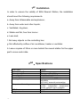
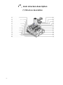
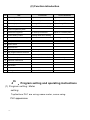
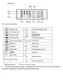
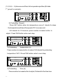
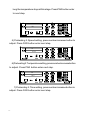
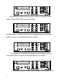
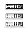
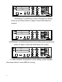
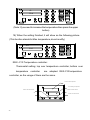
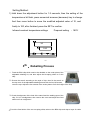
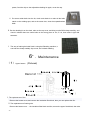
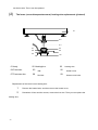
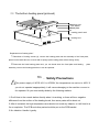
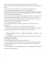
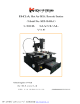
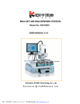
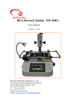
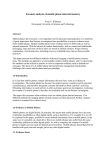
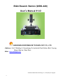
BGA Rework Station (WDS-420)
User’s Manual V1.O
SHENZHEN WISDOMSHOW TECHNOLOGY CO., LTD.
Address: 2nd F Building A, Quansheng Fa Industrial Park,Xintian Blvd, Fuyong
Street, Bao’an, Shen Zhen
Web: www.wdsbga.com
Shenzhen Wisdomshow Technology Co., Ltd Property in Copyright
-1-
Index
Item
Page
1. Installation requirements
03-03
2. Technical parameter
03-03
3. Introduction of main structrue
04-04
4. Program setting and operation
05-16
5. Reballing process
17-17
6. Equipment Maintenance
18-18
7. Safety cautions
19-19
Attached: Temperature Profiles
-2-
20-21
1
st
Installation
In order to ensure the validity of BGA Rework Station, the installation
should meet the following requirements.
a. Away from inflammable and explosives;
b. Away from water and other liquids;
c. Ventilated, dry place;
d. Stable and flat, free from tremor.
e. Less dust;
f. No heavy objects on the controlling box;
g. Not affected by airflow of air conditioner, heater or ventilator.
h. Leave a space of 30cm or more behind the rework station for the upper
part to move and rotate.
nd
2 、Specifications
Total Power
Upper Heating Power
Lower Heating Power
Power Supply
Overall Dimension
Locating Mode
Temperature Controlling
PCB Size
Weight of machine
-3-
3400W
1000W
Third zone: IR 2400W
AC 230V±10% 50/60HZ
L450*W420*H510mm
V-shape card slot, PCB holder can be
adjustable
by X and Y axes with universal jigs.
K-type thermocouple closed loop
control,
independent
temperature
control, precision up to ±3 degree
Max 320*310mm, Min 10*10mm
26KG
3
rd
、main structure description
(1) Structure description
-4-
(2) Function introduction
No
1
..O
Na
Function
Use method
Y-axis adjust of
top heater
Roma
Adjust the top heater
Right-back,left-forward
2
Z-axis adjust of top heater
Adjust the top heater
Right-up,left-down
3
Heaters group
Heating BGA when welding
Adjust through Z-axis
4
Top Nozzle
Make hot air focus on BGA
5
Lower temperature probe
6
PCB board supporter
n
Jedr
zeje
wski
7
8
9
10
m
Lower heating board
m
Start switch of lower heating
me
nameplate
me
To hold up PCB board
Adjust to a suitable place
Heating BGA when welding
According to setting
power switch
11
Crow-flow fan
12
PCB splint
13
Top programmable thermostat
14
Lower hot-air adjust
To hold up PCB board
15
Top hot-air adjust
Make hot air focus on BGA
16
Operation instructions
17
Overtemperature instructions
18
start button
19
Stop button
20
Cooling switch
4
th
To fix the splint
Turn left and right
Cool the PCB after heating
、 Program setting and operating instructions
(1) Program setting: Meter
setting:
Top/bottom PLC are using same meter, some using.
PLC appearance:
-5-
PLC panel instruction
Setting process:
First turn on the power supply
1) Choose temperature profile: (set groups) press PTN button (can save 10 groups
temperature profiles), Press PTN groups will be changed
-6-
(1, 2,3,4,5 …0) choose one of them for temperature profiles (We take
st
1 group for example)
PV
D IS P
T IM E
CO M
MV
MAN
SV
SET
PR O G
RUN
AU TO
HAND
1
SV
RU N
P IN
PR O
STE P
A L1
O U T1
P IN
PAR
SET
O U T2
P C4 1 0
A L TEC
2) Preheating: Slope(r)
Press SET button enter into temperature curve,r1 stands for slope
(the temperature will rise at the speed of 3℃ in one second)
3.00 stands for 3℃/second, press number increase button to
adjust. Press PAR button enter next step.
PV
D IS P
r1
T IM E
SV
C OM
SET
3 .0 0
1
PR O G
MV
MAN
SV
A L1
O U T1
O U T2
R UN
R UN
PIN
A U TO
H AN D
PAR
S ET
PIN
P RO
S T EP
P C4 1 0
A LT EC
3) Preheating:
Temperature (L),
Press number increase button to adjust,160 stands for preheating
temperature 160℃. Press PAR button enter to next step.
PV
D IS P
L1
T IM E
SV
CO M
S ET
P RO G
1 6 0 .0 0
1
MV
MAN
SV
A L1
R UN
PIN
P RO
S T EP
OUT 1
P C4 10
4) Preheating:
RUN
A UTO
H AN D
P IN
P AR
SET
OUT 2
A LT E C
Time (d),
Press number increase button to adjust, D stands for the time how
-8-
long the temperature stays at this stage. Press PAR button enter
to next step.
PV
D ISP
d1
T IM E
SV
COM
S ET
30
1
P RO G
MV
MAN
SV
A L1
O UT 1
OUT 2
R UN
P IN
P RO
S T EP
RUN
P IN
A U TO
HAND
P AR
S ET
P C 41 0
A LT E C
5) Preheating 2: Speed setting, press number increase button to
adjust. Press PAR button enter next step.
PV
D IS P
r2
SV
T IM E
COM
MV
MAN
SV
AL1
SE T
3 .0 0
PR O G
RUN
1
P IN
RUN
P IN
PRO
STEP
O U T1
AU TO
H AN D
PAR
SET
O U T2
PC 41 0
A L TE C
6) Preheating 2: Temperature setting, press number increase button
to adjust. Press PAR button enter next step.
PV
D ISP
L2
SV
T IM E
C OM
MV
M AN
S ET
PR OG
185
RUN
SV
1
P IN
A L1
R UN
P RO
S T EP
O UT1
P IN
A UTO
H AND
PAR
S ET
O U T2
P C 4 10
A LT EC
7) Preheating 2: Time setting, press number increase button to
adjust. Press PAR button enter next step.
-9-
PV
D IS P
d2
SV
T IM E
C OM
S ET
P ROG
30
1
MV
M AN
SV
A L1
R UN
P IN
P RO
S TEP
O UT1
R UN
P IN
A UTO
H AN D
P AR
S ET
O UT2
P C 410
A LT E C
8) Preheating 3: Speed setting, press number increase button to
adjust. Press PAR button enter next step.
PV
D IS P
r3
T IM E
SV
COM
S ET
3 .0 0
PR O G
MV
MAN
RUN
1
A U TO
H A ND
SET
P IN
PRO
S T EP
O U T1
O U T2
P C4 1 0
A LT E C
9) Preheating 3: constant temperature setting, press up and down
button to adjust. Press PAR button for confirm.
PV
D IS P
L3
T IM E
SV
COM
S ET
2 10
PROG
MV
1
MAN
P IN
RUN
P IN
RUN
PRO
ST EP
O U T1
A U TO
H AND
PAR
S ET
O U T2
PC4 1 0
A LT E C
10) Preheating 3: constant temperature time setting; press up
and down button to adjust. Press PAR button for confirm.
PV
D IS P
d3
SV
T IM E
COM
MV
MAN
S ET
PROG
30
SV
1
P IN
PC410
A L1
R UN
PRO
S TEP
O U T1
RUN
P IN
A U TO
H AN D
PAR
S ET
O UT2
A LT E C
11 Welding 4, press number key to change, Press PAR button
- 10 -
For confirm.
PV
D IS P
r4
T IM E
SV
COM
SET
3 .0 0
PROG
MV
MAN
RUN
1
A U TO
H A ND
SET
P IN
PRO
ST EP
O U T1
O U T2
PC 410
A LT E C
12) Welding 4: preheating constant temperature setting, press
Up and down button to adjust. And PAR button confirm.
PV
D IS P
L4
T IM E
SV
C OM
SET
P ROG
225
MV
M AN
RUN
1
A U TO
HAND
S ET
P IN
P RO
S T EP
O U T1
O U T2
P C 410
A LT EC
13) Welding 4: constant temperature time setting. press up/
down button to adjust. Press PAR button confirm.
PV
T IM E
SV
COM
S ET
P RO G
35
1
P IN
P C 41 0
14)
D IS P
d4
Welding 5:
MV
M AN
SV
A L1
RUN
PRO
S T EP
O U T1
R UN
P IN
A U TO
H AND
PAR
S ET
O UT2
A L T EC
the speed of heating setting. Press up and down
button to adjust. Press PAR button for confirm.
- 11 -
PV
D IS P
r5
T IM E
SV
COM
S ET
3 .0 0
PRO G
MV
M AN
R UN
1
A U TO
H AND
S ET
P IN
P RO
S TEP
O UT1
O UT2
P C 4 10
A LT E C
15) Welding 5: preheating constant temperature setting,
Press up and down button to adjust. Press PAR button for
Confirm.
PV
DISP
L5
T IM E
SV
CO M
SET
230
PROG
MV
MAN
RU N
1
AUTO
H AN D
SET
PRO
S T EP
O U T1
O U T2
PC410
A LT EC
P IN
16) Welding 5: Constant temperature time setting, press up and down
button to adjust. And press PAR button for confirm.
PV
D IS P
d5
T IM E
SV
COM
S ET
25
1
P IN
PROG
RUN
P RO
S T EP
MV
MAN
SV
A L1
O U T1
O U T2
P C410
RUN
P IN
A UT O
H A ND
PAR
S ET
A LT E C
17) After finished Temperature curve setting, press Number
Decrease button to show END for closing.
- 12 -
PV
D IS P
r8
SV
T IM E
COM
MV
MAN
S ET
E nd
P R OG
RUN
AUTO
HAN D
1
S ET
P IN
P RO
S TEP
O U T1
O U T2
PC 4 1 0
A LT E C
(Note: If you need to increase the temperature then press the upper
button)
18) When the setting finished, it will show as the following picture.
(This function stands for Max. temperature, do not modify)
P
D IS P T IM E
Hb
COM
V
S ET
P ROG
300
MV
M AN
RUN
A U TO
H AND
1
S
V
S ET
PC 41 0
A L T EC
PR O
O UT1
S T EP
O UT2
REX--C10 Temperature controller:
1
Thermostat setting; top over temperature controller; bottom over
P IN
temperature
controller
are adopted REX-C10 temperature
controller, so the usage of them are the same.
s h wo act u al t e mper at ur e
s h o w s etti n g t e mper at ur e
PV
nu mber de cr e as e butt on
nu mber de cr e as e butt on
SV
s et
nu mber i ncr e as e butt on
S ET
R KC
- 13 -
R E X -C 1 0
Setting Method:
1) Hold down the adjustment button for 1-2 seconds, then the setting of the
temperature a bit flash, press numerical increase (decrease) key to change.
And then move button to move the modified adjusted value of 10, and
finally to 100, after finished, press the SET to confirm.
Infrared constant temperature settings
Proposal setting :180℃
PV
30
SV
180
SE T
RKC
R EX-C 10
11
5
th
、Reballing Process
1. Fixed the BGA chip which need to be reballed on the under plate of the
adjustable reballing kit, and then adjust the No-spring slider to fix the
chip.
2. Choose the stencil according to the style of chip, then fix the stencil on
the top cover of the adjustable reballing kit and lock the four M3 screws,
cover the cap. Adjust the four screws of the under plate to fit for the height of the chip.
3. Check the alignment of the hole of the stencil and the welding spot of the
chip, if it is in misalignment, then remove the cover and adjust the fixed
slider until it is in alignment.
4.- Lock the fixed slider of the two no-spring slider, take out the BGA chip and wipe a layer of solder
- 14
paste, fixed the chip on the adjustable reballing kit again, cover the cap.
5. Put some solder balls into the kit, clutch and shake it to make all the balls
stand on the welding spot, and at the same time, clear the superabundant
balls.
6. Put the reballing kit on the desk, take out the top cover, and bring out the BGA cheap carefully, and
check it whether there are some balls on the wrong place or not, if it is, then make it right with
tweezers.
7. The way of making the balls fixed is using the Reballing machine, It
can heat the cheap medially. Up to now, we finished reballing.
6
th
、Maintenance
(1)Upper heater:(Pictured)
1. The replacement of fan:
Remove the heater cover, and remove the insulation fiber block, then you can replace the fan.
2. The replacement of heating wire
Remove the heater cover 、the insulation fiber block and fan, remove the upper fixed block, then take
- 15 -
out the hot wire. Then it can be replaced.
(2)
The lower (second temperature zone) heating wire replacement (pictured)
01
02
03
04
07
08
05
09
01 body
06
02 Heating Duct
03
Heating wire
04 Fan Holder
05
fan
06
Heater cover
07 Fan Holder Bolt
08
Fan Bolt
09
Heater cover bolts
Replacement of the lower hot air heating wire:
1
Remove the heater bolts, and then remove the heater cover,
2
Demolition of fans and fan mounts, remove the hot wire. Then you can replace the
heating wire,
- 16 -
(3)The bottom heating panel (pictured)
heating pad
lock screw
fixed plate
heating panel card
heating box
Replacement of heating plate:
1. Demolition of locking screws (4), remove the heating plate and the assembly of the fixed plate,
placed on the table which is covered with a sponge (with heating plate surface facing down).
2. Removed the fixed heating plate card, you can break down the fixed plate and heating
plate
assembly, remove the heating plate then it can be replaced.
7th
、 Safety Precautions
!The power supply of W DS -4 2 0 is AC230V, the temperature can arrive to 400℃. If
you do not operate inappropriately, it will cause damaging to the machine or even to
the operator. So you must strictly abide by the following matters:
1. Don't blow to the rework station directly when it is working, or there will be a negative
difference from the surface of the heating board, thus some parts will be burnt out.
2. After it is started, the high temperature area should not touch any objects, or it will lead to a
fire or explosion. The PCB and other parts should be put on the PCB bracket.
3. No vibration. Handle it gently.
- 17 -
4. Don't touch the heaters with your hands when it is working, or you will get hurt.
5. Don't use combustible spray, liquefied and flammable gas near the rework station after it is
started.
6. Don't try to re-equip the machine, or there may be a fire or an electric shock.
7. There are high-pressure parts in the circuit box. Don't disassemble it.
8. If some metals fall in the rework station when it is working, turn off the power immediately.
After it is cooled down, get the metal out, and clean the machine. If not, there may a smell
when the machine starts working next time.
9. When the rework station's temperature rises abnormally or smokes, turn off the power and
inform the service technicians to repair it. Turn off the power of the circuit box and the
machine while moving the rework station. Hold the plug when we remove the wire or it will
lead to a poor contact then the machine can't work very well.
10. Turn off the power when stop using it.
11. Don't put the rework station on the wires, or there may be a failure, a fire, or an
electric shock.
12. Before you use the machine, you must read the instructions attentively.
Note: when the machine works, it will produce some smell. So ensure the comfortable,
healthy and safe operation environment, please keep the air in circulation.
Under the following case, if it causes any damage, it will not in our
guarantee;
1)Do not operate according to the condition of the environment and methods of operation
that the manual book required;
2)The reason out of our product;
3)Not the transformation and maintenance of our company;
4)Do not operate accordance with the way of use that our company's products required;
5)The case that the temporal level of scientific and technological of our company was
impossible to predict;
6)Natural disasters or man-made destruction and such non-responsibility of the Company
premises, it will not in guarantee.
- 18 -
Normal BGA welding and disordering parameters
(for reference)
The temperature curve of lead welding
41*41
the temperature setting of the BGA welding:
preheating
insulation
heating
welding1
welding2
cooling
upper
160
185
210
235
240
225
time
30
30
35
40
20
15
bottom
160
185
210
235
240
225
time
30
30
35
40
20
15
slope
3.0
3.0
3.0
3.0
3.0
3.0
IR
180
38*38
the temperature setting of the BGA welding:
preheating
insulation
heating
welding1
welding2
cooling
upper
160
185
210
225
235
215
time
30
30
35
40
20
15
bottom
160
185
210
225
235
215
time
30
30
35
40
20
15
slope
3.0
3.0
3.0
3.0
3.0
3.0
IR
185
31*31 the temperature setting of the BGA welding:
preheating
insulation
heating
welding1
welding2
cooling
upper
160
180
200
215
225
215
time
30
30
35
40
20
15
bottom
160
180
200
215
225
215
time
30
30
35
40
20
15
slope
3.0
3.0
3.0
3.0
3.0
3.0
IR
180
The upper is the reference temperature of the lead BGA。
- 19 -
The temperature curve of Lead-free welding
41*41
the temperature setting of the BGA welding
preheating
insulation
heating
welding1
welding2
cooling
upper
165
190
225
245
255
240
time
30
30
35
55
25
15
bottom
165
190
225
245
255
240
time
30
30
35
55
25
15
slope
3.0
3.0
3.0
3.0
3.0
3.0
IR
210
38*38 the temperature setting of the BGA welding:
preheating
insulation
heating
welding1
welding2
cooling
upper
165
190
225
245
250
235
time
30
30
35
45
25
15
bottom
165
190
225
245
250
235
time
30
30
35
45
25
15
slope
3.0
3.0
3.0
3.0
3.0
3.0
IR
210
31*31 the temperature setting of the BGA welding:
preheating
insulation
heating
welding1
welding2
cooling
upper
165
190
220
240
245
235
time
30
30
35
40
20
15
bottom
165
190
220
240
245
235
time
30
30
35
40
20
15
slope
3.0
3.0
3.0
3.0
3.0
3.0
IR
210
The upper is the reference temperature of the lead-free BGA
Such as set 0 when the demolition of the cooling section of BGA
- 20 -