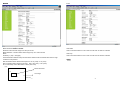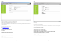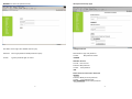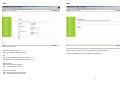
1
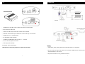
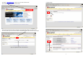
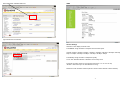
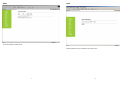
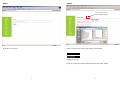
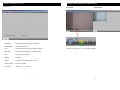
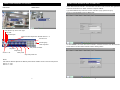
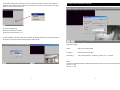
Thank you for purchasing our product.
Please read this User’s Manual before
using the product. Change without Notice
Safety Precautions
CAUTION
RISK OF ELECTRICAL
SHOCK. DO NOT OPEN !
CAUTION: TO REDUCE THE RISK OF ELECTRICAL SHOCK,
DO NOT REMOVE COVER (OR BACK), NO USER
SERVICEABLE PARTS REFER SERVICING TO
QUALIFIED SERVICE PERSONNEL.
This label may appear on the bottom of the unit due to space limitations.
The lightning flash with arrowhead symbol, within an equilateral triangle, is
intended to alert the user to the presence of insulated dangerous Voltage
within the product’s enclosure that may be sufficient magnitude to constitute
risk of electrical shock to persons.
The exclamation point within an equilateral triangle is intended to alert the
user to the presence of important operation and maintenance (servicing)
instructions in the literature accompanying the appliance.
VIDEO SERVER
WARNING: TO PREVENT FIRE OR SHOCK HAZARD, DO NOT
EXPOSE UNITS NOT SPECIFICALLY DESIGNED FOR
User’s Manual
Attention: installation should be performed by qualified service Personnel
only in accordance with the National Electrical Code or applicable local
codes.
Power Disconnect. Units with or without ON-OFF switches have power
supplied to the unit whenever the power cord is inserted into the power
source; however, the unit is operational only when the ON-OFF switch is
the ON position. The power cord is the main power disconnect for all
unites.
“CAUTION: Danger of explosion if battery is incorrectly replaced.
Replace only with the same or equivalent type recommended by the
manufacturer. Dispose of used batteries according to the manufacturer‘s
instruction.”
Warranty
and Service
During the warranty period (one year), we will repair or replace the DVR
free of charge.
Be sure to have the model number, serial number and vendor stick on
hard disk for service representative.
FCC Statement:
2
WARNING
SPECIFICATIONS
This device complies with Part 15 FCC Rules. Operation is subject to the following two conditions: (1)
This device may not cause harmful interference. (2) This device must accept any interference
received including interference that may cause undesired operation."
* Federal Communications Commission (FCC) Statement
WARNING
This Equipment has been tested and found to comply with the limits for a Class B digital device,
pursuant to Part 15 of the FCC rules. These limits are designed to provide reasonable protection
against harmful interference in a residential installation. This equipment generates, uses and can
radiate radio frequency energy and, if not installed and used in accordance with the instructions, may
cause harmful interference to radio communications. However, there is no guarantee that interference
will not occur in a particular installation. If this equipment does cause harmful interference to radio or
television reception, which can be determined by turning the equipment off and on, the user is
encouraged to try to correct the interference by one or more of the following measures:
- Reorient or relocate the receiving antenna.
- Increase the separation between the equipment and receiver.
- Connect the equipment into an outlet on a circuit different from
that to which the receiver is connected.
- Consult the dealer or an experienced radio/TV technician for help.
* You are cautioned that changes or modifications not expressly approved by the party responsible for
compliance could void your authority to operate the equipment.
Feature
- Support Embedded Linux
- Stand-alone TCP/IP Networking device platform
- Web server for remote setting
- Support pre-alarm and post-alarm
- Support intelligent motion detection (3 motion windows)
- Support RS-485 port with PTZ control
- Remote upgrade and configuration via network
Compression
- Support MPEG-4 & JPEG video compress
- Support MPEG-4/MJPEG dual bit streaming
- Support MP2, AMR-NB audio compress
- Support 2 way audio function, support ADPCM audio decompression
- Support 3G Handheld
Storage
- Support on-line backup in AVI & 3GP file format
- Support SD Card backup for event recording
Networking
- Support RTSP, RTP over TCP/IP, support unicast & multicast
- Support Ethernet LAN 10/100 Mbps for remote view/control, recording data backup, and firmware
update
- Optional Wi-Fi 802.11 b/g for supporting wireless LAN communication
- Support uPnP IGD device
I/O
- Support Digital I/O (One channel: 2 IN/2 OUT) for 2 sensor input, 2 relay out.
Power
- Support +12V DC power adapter input system
3
4
I/O
CONNECTION
VIDEO SERVER DEVICE
①
②
③
④
CAMERA
⑦
SPEAKER
⑩
⑤
⑥
⑧
X
⑨
① POWER LED / LAN LED: power on status and network connecting status
② MIC: Microphone cable input
③ LINE IN: CD / MP3 player audio input, LINE OUT: Audio speaker
④ VIDEO IN: Camera video input / VIDEO OUT: Camera video loop out connection
X
⑤ POWER: DC 12 V / 1 A adaptor input
⑥ RJ-45: Network cable connection
X
⑦ ALARM IN / ALARM RELAY OUT / RS 485: + / -- connector
⑧ SD card: Secure Digital card interface
⑨ USB. B type (Not available)
⑩ DEFAULT: Set to factory default
* Microphone has the priority output if line input at the same time.
NOTICE:
1. Install Video_Server_Viewer_Setup.exe of CD-R disk. Direct X 9.0 is required.
2. Go to IE browser to setup the IP address such as PPPoE & DDNS, DHCP or STATIC type. The
default IP address is 192.168.1.51
3. Or just use 192.168.1.51 to log in video server client
5
6
OPERATION UNDER IE BROWSER
OPERATION UNDER IE BROWSER AFTER LOGIN SUCCEDED
Type the default video server IP in IE browser address bar.
192.168.1.51
Display:
Network:
PPPoE:
DDNS:
Video:
Audio:
Motion:
SMTP:
FTP:
Account:
NTP:
UPnP:
Status:
Reset:
Reboot:
Upgrade:
Default name and password is sysop
Suggest computer system;
-
CPU : up to P4-2.4 G
RAM : up to 256 MB, 512 MB will be better
VGA card : nVidia MX 400, up to 32 MB VRAM
Windows 2000 / XP / Vista
Live image display
Network function setup
ADSL dialing setup
DDNS setup
Video transfer type setup
Audio transfer type setup
Motion detection setup
Simple Mail Transfer Protocol setup
File Transfer Protocol
Login ID and password setup
Network Time Protocol
Universal plug & play
Connection Status of Video Server
Return to factory default
Device re-power
Firmware update
7
8
* See each function details for all next pages.
DISPLAY
Click DISPLAY to start image running.
Network
DHCP: Dynamic Host Configuration Protocol
Brightness: Live image brightness adjust. 1 ~ 254
Ethernet Interface
Saturation: Live image saturation adjust.
1 ~ 254
Contrast:
Live image contrast adjust.
1 ~ 254
Apply:
Click Apply button after image adjustment
DHCP Client: ON / OFF (Use Video Server Viewer to detect connection IP)
IP Address:
Do not alter temporarily (Except LAN IP or WAN IP)
Subnet Mask: Do not alter temporarily (Except LAN or WAN subnet mask)
Voice Alarm: ON / OFF. To send out a warning voice.
Gateway:
Do not alter temporarily (Except LAN or WAN gateway)
DNS1: Type DNS IP 1 address
DNS2: Type DNS IP 2 address
9
10
PPPoE
DDNS
Point to Point Protocol over Ethernet is a proposal specifying how a host personal computer (PC)
interacts with a broadband modem (xDSL, cable) to achieve access to the growing number of high
speed data networks.
If user is going to use PPPoE connection, please obtain your login name and password from local ISP
Company
User Name: User network dialup login name
Password: User network dialup login password
Password Retype: User login password re confirm
Auto Start reboot: Auto connect after video server power reboot
The free Dynamic DNS service allows you to alias a dynamic IP address to a static hostname in any of
the many domains we offer, this allow your computer to access from locations on the Internet more
easily. We provide this service, for up to five (5) hostnames, free to the Internet community.
The Dynamic DNS service is ideal for a home website, file server, or just to keep a pointer back to your
home and office PC so you can access video server via internet. Using one of the available third-party
update clients you can keep your hostname always pointing to your IP address, no matter how often
your ISP changes it. No more fumbling to find that piece of paper where you wrote down your IP
address or e-mailing all your friends every time it changes. Just tell them to visit your
name.dyndns.org instead!
Service Configuration: Enable / Disable
DDNS Service:
DynDNS.org / 3322.org
Next, obtain a free DDNS according to the lists it supplied.
Host Name:
User Name:
DDNS host name
DDNS supplied login name
Password:
DDNS supplied login password
If host Name is cv1000, then the correct typing is cv1000.dynDNS.org
DDNS connection is build on PPPoE
11
12
Ex: Enter in www.dyndns.com to apply a free account and host name.
Click Create Account to make a new ID name.
Logged In page
Click Add Host Services:
Fill in all the personal information, password, email requested; please go to user’s email
account to active your new account. Return to DynDNS website; click Account to long in page.
Type your applied Username and Password
Click “Add Host Service”
Add static DNS Host:
13
14
Select Static DNS: add Static DNS Host
Video
Type a Hostname user decided.
Stream1 Settings
OSD timer: Time display mode ON / OFF
Fixed BitRate: Image resolution is subjected to the transmit speed.
16 Kbps/ 32 Kbps / 48 Kbps / 64 Kbps / 128 Kbps / 192 Kbps / 256 Kbps / 320 Kbps / 384 Kbps 448
Kbps / 512 Kbps / 576 Kbps / 640 Kbps / 704 Kbps / 768 Kbps / 1Mbps
Fixed Quality: Image resolution is subjected to quality.
No useful
So So / OK / Not Bad / Medium / Standard / Good / Pretty Good
Framerate: Scanning frame per second among internet (5 / 10 / 15 / 20 / 25 /30)
*Stream 1 frame rate only to 15 while Stream 2 is using
Resolution: Video resolution selection (NTSC:176x120 / NTSC:352x240 / NTSC:720x480)
15
16
Stream2 Settings
Audio
Dual Bitstream: Disable / MPEG4 / JPEG
MPEG4 Settings
Fixed BitRate: Image resolution is subjected to the transmit speed.
16 Kbps/ 32 Kbps / 48 Kbps / 64 Kbps / 96 Kbps / 128 Kbps / 192 Kbps / 256 Kbps / 320 Kbps / 384
Kbps 448 Kbps / 512 Kbps / 576 Kbps / 640 Kbps / 704 Kbps / 768 Kbps / 1Mbps
Fixed Quality: Image resolution is subjected to quality.
So So / OK / Not Bad / Medium / Standard / Good / Pretty Good
Resolution: Video resolution selection
QCIF: 176x120 / CIF: 352x240 / D1:720x480
Framerate: Scanning frame per second among internet
5 / 10 / 15
MJPEG Settings
Quality: Video quality
1 ~ 10
Resolution: Video resolution selection
QCIF: 176x120 / CIF: 352x240 / D1:720x480
Framerate: Scanning frame per second among internet
5 / 10 / 15
Audio Settings
Audio Channel: Select Mono or Stereo sound
Sample Rate: 16000 / 22050 / 32000 / 48000
More natural under higher rate
Save:
Codec Settings:
MP2 Bitrate:
32kbps (sound clarity low)/ 48kbps (sound clarity normal) / 64kbps (sound clarity good)
AMR Bitrate:
MR 59 / MR 67 / MR 74 / MR 102 / MR 122 / MR 475 / MR 515 / MR 795
Save: Click save button after value change
17
18
Event:
MOTION
Alarm Action: Save alarm file to mail or FTP account.
Motion detection setup
Motion detection Enabled / Disable
Detection Frame Interval: Image scan rate per second
Motion Detection 1: Motion detect window. Support up to 3 motion window.
Name:
Sensitivity: 1 (low) ~ 254 (high)
Threshold: Motion detection setup window. Motion detection will be activated when motion range
exceed the setup window.
Start Coodinate: Motion detection start point. EX: X: 30 (<352) / Y: 30 (<240)
Stop Coodinate: Motion detection end point. EX: X: 60 (<352) / Y: 60 (<240)
Ex: In Video Setup, select Resolution = NTSC (352 x 240)
Alarm Mail:
Alarm event files transfers to user’s mail account when an alarm is activated.
Alarm Ftp:
Alarm event files transfers to user’s FTP account when an alarm is activated.
Apply:
(0, 0)
Motion Detection 1
30, 30
Live image
60, 60
(352, 240)
19
20
SMTP
FTP
Email account login name / password / address setup
SMTP Server: Enter Mail server type in. Ex: hotmail
Some mail servers will stop the E-mail that the same source continuity. Please check the mail server
policies restriction.
Recipient: User’s email address
Ex: [email protected]
FTP setup
FTP Server: FTP server select
User can get a free FTP server from the lists or user install a FTP server in user’s computer.
FTP Port: File transfer port setup.
Username: FTP server, user login name
Password: FTP server, user login password
Remote Folder: File saved path. User needs to add a new path and folder.
Passive Mode: FTP passive mode on or off selection.
Username: User’s email login name
Ex: HS168
Password: User’s email login password
Ex: 168HS
Apply: Click apply button after value change
FTP Test: File sending to FTP server test
Authentication Method: PLAIN / LOGIN
Apply: confirm
SMTP Test: Mail sends and receive test
21
22
Account: User name and password modify
ID and password setup page
User Name: User’s login name. Default name is sysop
Change Password
Password: User’s login password. Default password is sysop
New Password: Type new password
Confirm:
New password confirm
Confirm:
CHANGE
Type the password again to confirm
ADD New Account
Account: New account
Password: New password
Confirm: New password
ADD
Delete Account or Reset User Password
DELETE
Password: Modify account’s password
Confirm:
Type password again
SET PASSWORD Confirm a new password.
23
24
NTP
UPnP
Network Time Protocol
When the UPnP Services is set to “ON”, it would be more easy for the video server stream to pass
through router or IP sharing if there is 2 gateways at a local network system.
Synchronized with Time Server
NTP Server: clock1.redhat.com (Default).
Router and IP sharing must also equipped with UPnP service.
EX:
time.nist.gov (Windows XP time zone reference)
time.windows.com (Windows XP reference time zone)
Manual Update
Date : User select date by manual
Time : User select time by manual
Synchronized with PC
Date : Synchronized with computer date
Time : Synchronized with computer time
25
26
Status
Reset
Connection Status of Video Server
Reset all function set up to default or reset one by one.
27
28
Reboot
Upgrade
Click “browser” to select
version code from supplier.
Select in-coming source and then click update to start updating.
Re-power on video server.
Updating process bar.
Please go to reset page and then default all function after version update.
29
30
VIEWER CLIENT INTERFACE: SCREEN DISPLAY
VIEWER CLIENT INTERFACE: Functions
Functions set:
①
②
Full screen
③
⑧ Screen: Full / Quad
④
⑤
⑥
Quad screen
⑦
⑨ Camera 1 ~ 4
① CONNECT:
Detect and Log in video server IP address
② DISCONNECT:
Log out video server
③ REC:
Video stream record (Single camera recording)
④ SETTING:
Connecting status display / PTZ dome setup
⑤ PTZ:
PTZ control panel shows
⑥ EVENT:
Event list
⑦ AUDIO:
Two ways conversation mode on or off
⑧ Screen display:
Full screen / Quad
⑨ Full screen:
Camera 1 / 2 / 3 / 4 select
31
Click mouse to select 1 / 2 / 3 / 4 full screen display.
32
VIEWER CLIENT INTERFACE: PTZ CONTROL
Full screen
VIEWER CLIENT INTERFACE: MAEK A CONNECTION
Quad screen
Under desired camera channel 1, click left button of mouse to enter, and then click right button of
mouse for the function icon. Select “Connect” to input IP address.
Type default address rtsp://192.168.1.51:554; username: sysop; password: sysop
Or rtsp://cv1000.DynDNS.org:554 for DDNS type.
PTZ IRIS Close
PTZ direction up / down / left / right
PTZ OSD
PTZ IRIS Open
Channel number depends on desired camera 1 ~ 4
Function exit
Presets group
Total 16 presets
Set preset
Zoom in / out
Or click CONNECT, and then select Server Address, IP address would be auto detected if the video
server device is at same subnet network under IP sharing device.
Auto preset tour starts
Call preset
Clear preset
Stop auto preset tour
Notice:
PTZ dome ID defines depends on different product brand. Please choose correct ID and protocol.
Pelco P: 0 ~ 254
Pelco D: 1 ~ 255
33
34
After the first camera video connection, user can continue to connect to another camera channel.
Example: Under desired camera channel 4, click left button of mouse to enter, and then click right
button of mouse for the function icon.
VIEWER CLIENT INTERFACE: SETTING
Connect: IP address link
Disconnect: IP address terminate
Audio Source: Audio mode on / off
Or click CONNECT, and then select Server Address, IP address would be auto detected if the video
server device is at same subnet network under IP sharing device.
Application setting
Status:
Video server working status
Configure:
Call IE function set up page
PTZ setting:
PTZ protocol PELCO_P or PELCO_D select / ID 1 ~ 16 select
Notice:
PTZ dome ID defines depends on different product brand. Please choose correct ID and protocol.
Pelco P: 0 ~ 254
Pelco D: 1 ~ 255
35
36
Status: Video server working status window
Click confirm to two way conversation mode on.
Blue color:
Under desired camera channel, click left button of mouse to enter, and then click right button to select
Audio Source. User now can hear sounds from live environment.
Now change to yellow color, click AUDIO again to cancel. Voice alarm stop!!
Camera 4 is recording.
Red color
Under desired camera channel, click left button of mouse to enter, and then click REC icon, system
starts to record the camera to default path C:\record folder. Click REC icon again to cancel video
record.
Yellow color
On Audio Source mode, click left button of mouse to enter. And then click AUDIO to two way
conversation mode. See next page.
CH: Camera 1 ~ 4; IP: Current IP address; Status: Current working status
REC file: Record path; Start rec time: Beginning of record time;
PreStatus: Previous working status
37
38
IE Configure. Functions setup same as IE browser.
Q & A:
1. After function value changed and saved, user needs to wait while back to display mode.
2. Date and time caption shake if resolution is too low.
3. Time can only be set up 2038 / 01 / 18. This is a specification of an electric apparatus
4. User needs to reconnect video server after IP address is changed.
5. Sometimes the video displaying on viewer or IE is slower than actual live because the network
transmission jam or resolution defines.
6. When network DHCP is ON, after IP address is saved; at this time if some mess words shows up,
user please reset(the device reset button) video server.
7. NTP values always the same even date and time adjusted.
8. If Stream 2 Settings is saved, the live display is still on stream1, user needs to change to stream 2
until next display shows up.
9. Under desired camera channel, if user click left button of mouse to enter, the channel would have a
little flash because the image is afresh.
10. Every event always triggered after previous event finished.
39
40