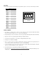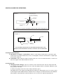
1
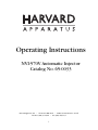
Operating Instructions
NVI-570V Automatic Injector
Catalog No. 65-0033
Harvard Apparatus, Inc. • 84 October Hill Road • Holliston, Massachusetts 01746
Toll Free: (800) 232-2380 • Fax: (508) 429-5732
1
PACKING LIST:
Each unit includes the following components:
a.
b.
c.
d.
e.
f.
g.
h.
Injector Head with Cord
Control Box
Power Supply with Cord
1 vial - 3-1/2” Capillaries
1 vial - 7” Capillaries
1 - Replacement O-Ring Kit
1 - Allen Wrench
1 - 2” needle
OPERATION:
The injector head should be mounted in a micromanipulator. Brinkman model MM-33 is suitable. The aluminum barrel assembly, maximum OD11 mm, provides an ideal clamping surface.
This equipment is ready for use as received; it does require pulled capillary tips.
NVI-570V operation depends greatly on the use of tips prepared from the glass provided. We cannot guarantee that
glass capillaries with other dimensions will work!
Pulled capillary tips must be backfilled with oil (or other non-compressible fluid) before attachment on injector.
Silicone or mineral oil as well as water are commonly used. Backfilling is facilitated by using a 30 gauge needle, 2”
long; or, disposable spinal needle. The NVI-570V will not operate properly without oil!
The three control switches work as follows:
FILL:
Reverses plunger movement while button is depressed. Buzzer will sound at extreme fill position. Fill speed
is 46 nL/sec.
EMPTY: Plunger moves forward while button is depressed. Buzzer will sound at extreme position. Empty speed is
approximately twice as rapid as fill; i.e. 110 nL/sec.
A faster speed (230 nL/sec) can be obtained in fill and empty modes. To fill faster, hold down the fill button
and press the empty button once. To empty faster, hold down the empty button and press the fill button
once. The plunger will maintain the faster speed until the control button is released. The unit will always
start in the slower speed.
INJECT: Depressing button injects a predetermined volume of solution.
GETTING STARTED:
A.
Plunger “Home” Position: Before using the injector, the wire plunger must be in the “home” position. When
in the “home” position, the tip of the wire plunger will be located even with or slightly recessed from the end of
the collet when the collet is tightened.
When the injector head is plugged into the control box and the power supply is connected, the injector will
assume it is in the “home” position. If it is not in this position, you will not be able to fill the micropipettete to
its maximum capacity of 5 µl.
NOTE: UNIT IS SHIPPED FROM THE FACTORY IN THE “HOME” POSITION.
2
GETTING STARTED (Contd):
To reposition the wire plunger, simply connect the injector and the power supply to the control box. If the wire
plunger is extending beyond the collet, press and hold the “FILL” button until the plunger retracts to the end of
the collet, then release the “FILL” button. At this point, unplug the power supply connector from the control
box, count to five, and reconnect the power supply. An audible “beep” will be heard. The unit is now in the
“home” position and ready to have the backfilled micropipette positioned onto the wire plunger. Do not forget
to loosen the collet before trying to install a micropipette onto the injector.
If you cannot see the wire plunger when looking into the collet, it is retracted too far into the injector head. To
reposition, press and hold the “EMPTY” button until the wire plunger tip is visible and flush with the end of the
collet. Next, unplug the power connector from the control box, count to five, and reconnect. An audible “beep”
will be heard and the unit is again in the “home” position.
SUGGESTION:When you are finished using the unit for the day, make sure the wire plunger is in the proper
position before it is unplugged.
B.
Backfilling the Micropipette: For proper injection, the pulled micropipettes must be backfilled with oil.
Inject lightweight mineral oil into the micropipette from the back end until filled. Carefully slide the
micropipette onto the wire plunger making sure it goes through the first O-ring and seats properly into the
white spacer. This is done by “feel” and may take some practice. Tighten the collet securely.
At this point, push and hold the “EMPTY” button on the control box. The wire plunger will extend forcing
excess oil out of the micropipette tip. Hold the “EMPTY” button until a double “beep” is heard. The plunger is
now fully extended. To check, measure with a ruler. The wire plunger should extend approximately 1-1/16”
(26 mm) from the end of the collet.
Check for the presence of air bubbles in the micropipette. None should be present since they could influence
the injection procedure.
NOTE: IF AIR BUBBLES ARE PRESENT, REPEAT THE BACKFILLING PROCEDURE.
C.
Filling the Micropipette with a Sample: After installing the micropipette on the injector, place the tip into
the sample and hold the “FILL” button until the audible “beep” is heard. Maximum volume the micropipette will
contain is 5 µl. If maximum volume is not required, release the “FILL” button and filling will stop.
D. Fast “FILL” and “EMPTY”: The standard “FILL” rate is 23 nL/ sec. The standard “EMPTY” rate is 46 nL/sec.
A faster speed of 230 nL/sec can be obtained in both fill and empty modes. To fill fast, hold down the “FILL” button and press the “EMPTY” button once. To empty fast, hold the “EMPTY” button and press the “FILL” button
once.
NOTE: THE PLUNGER WILL MAINTAIN THE FASTER SPEED UNTIL THE CONTROL BUTTON IS RELEASED.THE
UNIT WILL ALWAYS START IN THE SLOWER SPEED.
E.
“INJECT” Button: Once the micropipettete is filled, installed, and injected into the oocyte, pushing the “INJECT”
button one time will dispense the programmed volume.
By depressing the inject button a second time, the same amount of sample will be dispensed again.
INJECTION RATE: 23 nL/sec.
3
DIP SWITCH:
Located on side of control box. The following “code” permits the operator to select any of the following 16 volumes.
VOLUME
1
2
3
4
4.6 nL
D
D
D
D
9.2 nL
U
D
D
D
13.8 nL
D
U
D
D
18.4 nL
U
U
D
D
23.0 nL
D
D
U
D
27.6 nL
U
D
U
D
32.2 nL
D
U
U
D
36.8 nL
U
U
U
D
41.4 nL
D
D
D
U
46.0 nL
U
D
D
U
50.6 nL
D
U
D
U
55.2 nL
U
U
D
U
59.8 nL
D
D
U
U
64.4 nL
U
D
U
U
69.0 nL
D
U
U
U
73.6 nL
U
U
U
U
1
2
3
4
Dip Switch
GENERAL COMMENTS:
1.
Wire plungers on all injectors have a point on one end. This wire can be reversed if a blunt end is desired.
The point should allow bubbles in the oil to escape when backfilling tips.
2.
The preferred tip size seems to be 20 microns. Some users report using 30 micron tips with no increase in mortality.
3.
Injections of 25 nL or less generally requires smaller tips, normally 10 microns.
4.
A broken tip seems preferable for oocyte injection. Sharp polished tips tend to “skip”.
5.
Virtually any oil is suitable for backfilling.
6.
The use of a plastic screen in a petri dish is commonly used to hold eggs for injection. Also reported is the use of
a layer of silicone (silastic) in a petri dish with a “V” groove cut after hardening.
7.
A reported technique positions a drop of mercury between the oil and the sample in the micropipette. This apparently acts as a brake allowing better control of injection rate.
8.
An excellent reference to all procedures involving the Xenopus oocyte is:
Kay B. and H. Peng,“Xenopus Laevis: Practical Uses in Cell and Molecular Biology”, Methods in Cell Biology,Vol. 36.
Academic Press
4
CLEANING AND SERVICING INSTRUCTIONS:
Figure 1
Plastic Sleeve (spacer)
This spacer should be placed
between the two black O-rings
Black O-ring
(large hole)
Plunger
Aluminium Barrel
Glass
Sealing Black O-ring
(small hole)
Collet
Note: Plastic sleeve (spacer) should be positioned with “shelf” facing pipet tip.
Figure 2
Nut
Collet
Aluminum Barrel
Motor Housing
Delrin
Body Tube
DO NOT REMOVE THE MOTOR HOUSING FROM THE DELRIN BODY TUBE.
DAMAGE TO THE MOTOR WIRES MAY RESULT. THIS WILL VOID ALL WARRANTIES.
Cleaning Recommendations
A. The Injector (see figures 1 and 2 above): Remove collet, O-rings, and the spacer. Clean these parts
and the injector head unit with alcohol. Do not soak in liquid or autoclave the NVI-570V. A simple wipe
down will be sufficient.
B. Control Box: Wipe off the box with a clean dry cloth. Do not use solvent-based cleaners. Solvents can
dissolve the print on the label and discolor the box.
Servicing the Unit
A. Changing the Wire Plunger: The most common service function that the end user will perform will
be to change the wire plunger when necessary. If the wire plunger is bent, it should be replaced for optimal operation of the unit
To change the plunger, remove the collet, O-rings, and white spacer.
The plunger wire can be replaced if accidentally bent. This wire is held in place by two set screws. Access
by removing the black aluminum barrel. Hold the motor housing in one hand and unscrew the aluminum
barrel with the other hand (turn counter-clockwise). Do not remove the adjacent large black nut.
5
Servicing the Unit (Contd)
CAUTION: IF YOUR UNIT HAS A HEX NUT BETWEEN THE ALUMINUM BARREL AND
THE MIDDLE SECTION, DO NOT UNSCREW THIS NUT. HOLD THE NUT AND UNSCREW
THE ALUMINUM BARREL FROM IT. DO NOT REMOVE THE ADJACENT LARGE BLACK NUT.
IMPORTANT: Correct sequence and orientation of the O-rings and spacer is critical for proper operation
of the injector (see next section and figure 1 on previous page)
Any other service functions should only be attempted after calling our technical service department at:
800-232-2380.
B. To Change O-Rings: After a period of time and/or heavy use, some leakage of oil during injection might
be observed near the collet. To correct this, the O-rings must be replaced. A new O-ring kit is included
with each NVI-570V. Refer to figure 1 on previous page since the proper installation is critical to prevent
leaking of the unit during injection.
Proper sequence of the two black O-rings and the white spacer is as follows: From the pipet body, the
small hole O-ring goes first, followed by the white plastic spacer with recess facing the tip, followed by
the O-ring with the larger hole. The collet screws secure everything.
C. Gasket Replacement: The gaskets, holding and sealing the capillary tips, need periodic replacement.
OPTIONS AND REPLACMENT PARTS:
Catalog No.
Product
65-0036
Foot Switch, provides hands off control. This Injector is provided with a 3.5 mm jack
to allow use of this Foot Switch or other remote control devices.
Replacment Wire Plunger
3-1/2” Capillaries, pkg. of 100
2” needle
65-0038
65-0099
65-0037
6