1
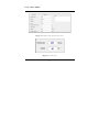
USER MANUAL D30 Particle Size Measurement System CORALTEC INC. User Guide & Operation Manual CORALTEC INC. 130 Konrad Crescent • Suite 11 Markham, ON L3R 0G5, Canada Phone 1.844.604.6234 • Email [email protected] • Web: www.spraysizer.com Manual Release Date: February 2015 Manual Version: V2.0 Contents 1 Package Contents ............................................................................................................. 7 2 Hardware Components ................................................................................................... 8 3 2.1 Sampling Cones (Outer & Inner)............................................................................. 9 2.2 Bubble Level Indicator ............................................................................................ 10 2.3 Detector & Laser Caps ............................................................................................ 10 2.4 Laser and Detector ................................................................................................... 10 2.5 Inner Channel ........................................................................................................... 11 2.6 Laser Alignment Set Screws.................................................................................... 11 2.7 Start Bottom & Indicator LEDs ............................................................................ 11 2.8 Batteries ..................................................................................................................... 13 2.9 Volume Sensor.......................................................................................................... 13 2.10 Liquid Container ................................................................................................. 14 2.11 Bluetooth® ........................................................................................................... 14 2.12 Blockage Cone..................................................................................................... 15 Getting Started ............................................................................................................... 16 3.1 4 Battery Installation ................................................................................................... 16 Operation Procedure ..................................................................................................... 18 4.1 Pre-measurement Procedure .................................................................................. 18 4.2 Measurement Procedure.......................................................................................... 20 4.3 Data Analysis Procedure ......................................................................................... 21 4.4 Volume Sensor Teaching ........................................................................................ 21 5 Theory of Operation ..................................................................................................... 24 6 D30 Software .................................................................................................................. 26 7 6.1 Installation & Minimum Requirements ................................................................ 26 6.2 Software Sections ..................................................................................................... 27 6.2.1 Pre-Measurement Setup ............................................................................... 28 6.2.2 Measurement Results .................................................................................... 32 6.2.3 Droplet Frequency ........................................................................................ 34 6.2.4 Size Distribution ............................................................................................ 35 6.2.5 Menu Bar ........................................................................................................ 35 6.2.6 Connection ..................................................................................................... 38 Measurement Result Evaluation .................................................................................. 40 7.1 D30 Measurement Limitations ............................................................................... 40 7.2 Operating Condition Limitations........................................................................... 43 7.3 Proper Result Identification.................................................................................... 44 8 Maintenance .................................................................................................................... 47 8.1 Laser Alignment ....................................................................................................... 48 9 Troubleshooting ............................................................................................................. 50 10 Accessories ...................................................................................................................... 55 11 TERMS OF USE, WARRANTY & LIABILITY WAIVER.................................. 57 11.1 Terms of use ........................................................................................................ 57 11.2 Exclusive Obligation .......................................................................................... 57 11.3 Warranty ............................................................................................................... 57 11.4 Warranty Limitation: .......................................................................................... 58 11.5 Guarantees ........................................................................................................... 60 11.6 Limitation of Liability......................................................................................... 60 11.7 Other Statements ................................................................................................ 60 11.8 General ................................................................................................................. 61 11.9 Modification of Terms and Conditions ........................................................... 61 11.10 12 Entire Agreement ............................................................................................... 61 Index ................................................................................................................................ 63 P A C K A G E C O N T E N T 1 Package Contents Once you open your new D30. You will find the following items included in the package: 1. 2. 3. 4. 5. D30 measurement device Four AAA batteries A blockage cone The user manual A software CD Figure 1 shows different components that are included in the package. Device Blockage Cone Batteries Manual Software CD Figure 1 Items included in the package 7 H A R D W A R E 2 Hardware Components D30 includes several components which are important elements of size measurement. These components include a laser module, signal detector, the sensors, container and electronics processing unit. Figure 2 shows various components of the device, explaining various components inside it. 1 6 10 7 2 4 3 9 15 12 14 11 13 18 16 17 Figure 2 Exploded view of D30 8 8 5 H A R D W A R E 1. 2. 3. 4. 5. 6. 7. 8. 9. 10. 11. 12. 13. 14. 15. Outer sampling cone Inner sampling cone Main body Bubble level indicator Detector cap Laser cap Laser detector Laser Inner channel Laser alignment set screws Start bottom 16. 17. 18. 19. Indicator LEDs Battery compartment Battery door Volume sensor compartment Inner rubber plug Outer plug Stand screw Blockage cone (not shown in the picture) 2.1 Sampling Cones (Outer & Inner) The sampling cones sample a small part of the spray for droplet size measurement. There are two sampling cones, the outer and the inner. They are designed to sample a small part of the spray droplets such that the sampled droplets pass through the laser beam with minimal disturbance. 9 Warning: the sampling cones should be installed properly to ensure accurate droplet sampling. H A R D W A R E 2.2 Bubble Level Indicator A bubble level indicator is installed on the device to ensure proper measurement of the droplet size. It allows user to align the device with horizontal surface. 2.3 Detector & Laser Caps Two screwing caps protect the laser and the detector on both sides of the device. Opening the caps will give you access to the laser and detector. Please avoid opening them at all times. If laser re-adjustment is required, please contact our support team for more information. Warning: when handling the device be careful of the laser side. Do not drop or hit it as it may affect the alignment. 2.4 Laser and Detector A laser and a detector, located on each side of the device, are the essential elements of the D30. They are aligned with respect to each other prior to shipment. Do not temper with neither the laser nor the detector. The accuracy of the size measurement is critically dependant on the laser-detector alignment. Warning: do not look inside the device when it is on or a measurement is in progress. The laser beam can be harmful to your eyes. The laser module used in the device is a 3.5mW laser in red visible range. It is a round laser beam with wave length of 635nm. 10 H A R D W A R E 2.5 Inner Channel The inner channel houses the laser and detector and protects the laser beam. It is also connected to the liquid container. The inner channel is covered by the main body. Careful handling of the device is required to avoid possible device damage. 2.6 Laser Alignment Set Screws The laser module is aligned using three set screws. To access the set screws you need to unscrew the caps. Set screws are very sensitive and their small movement will affect the laser beam direction and orientation. Note: 1.5mm Allen key driver is required for the set screws. 2.7 Start Bottom & Indicator LEDs There are total of four LED lights on the body of D30. The indicating function of each LED light is provided in Figure 3. 11 Tip: always return the device to its protective case after usage to avoid unnecessary damage. H A R D W A R E POWER ON/OFF CONNECTION BATTERY SENSOR Figure 3 Function indicating LED lights The type of flashing of a LED refers to a predefined device functional as follow: Blue (Solid): Device is connected to D30 Software via Bluetooth®. Green (Solid): D30 is powered on. Green (Off): D30 has to be turned off as soon as possible and batteries should be replaced. Amber (Solid): Volume sensor teach in progress. Red (Solid): Low battery level. The batteries needs to be changed immediately. 12 H A R D W A R E 2.8 Batteries The device is supplied with four AAA batteries. It is highly recommended to use the long lasting batteries to have longer operation time. Batteries should be removed when the device is not used for a long time. Warning: to prevent loss of data, immediately change the batteries once the red light is on. 2.9 Volume Sensor In order to accurately measure the volume of the collected liquid, a volume sensor is mounted on the container. The volume sensor works based on capacitance properties of the approximate medium. Before using the device for the first time, you need to teach the sensor using the liquid you want to spray from your nozzle. 13 Note: you need to teach the sensor every time you want to use different type of liquid. Otherwise, the volume measurement will not be accurate. Refer to Section 4.4. H A R D W A R E 2.10 Liquid Container There is a liquid container in the middle of the device which is used to collect spray sample. You need to empty and clean (if necessary) the container after each measurement. The access is provided to the container from the bottom of the device. It is a cylindrical container with the inner diameter of 16.5mm and height of 102.8mm, which can hold up to 22cc of liquid. The maximum water that can be collected for measurement is 15cc. 2.11 Bluetooth® Warning: you need to stop the spray, take out the device from the spray, or place the blockage cone after each measurement to avoid the container overflow and possible device damage. D30 communicates with its computer software via a Bluetooth® module. The module can work within a range as long as 100m, however it is recommended to be as close as possible to the device during the measurement to avoid loss of communication and data. The Bluetooth® module works best in non-metal environments. In an environment surrounded with metal (e.g. closed chambers) you may face difficulty in connecting to the device. 14 H A R D W A R E 2.12 Blockage Cone The blockage cone is a multi-purpose tool that can be used for several functions. Its primary application is to block the flow of the spray into the liquid container before or after the start of the measurement. It also can be used for closing the top opening while the device is not in use in order to prevent dust collection on the laser and detector modules. It also can be used while aligning the laser to prevent possible laser exposure from the top opening. 15 G E T T I N G S T A R T E D 3 Getting Started To start using the device, first install the supplied batteries. Once the batteries are properly installed, D30 can be used immediately for measurement. Please read through the operation procedure section to familiarize yourself with the correct method of measurement. 3.1 Battery Installation 1. 2. Unscrew 4 screws on the battery compartment. The screws are M3 and you need an Allen key (size 2.5mm) (not supplied) to unscrew them. Place the batteries in the proper orientation and screw the four screws tightly. 16 Warning: to prevent liquid leakage while testing, make sure the battery compartment is screwed in place firmly, but do not over tighten them. G E T T I N G S T A R T E D M3 Screws Battery door Batteries Figure 4 Battery installation 3. Proceed to operation procedure on how to perform a measurement. 17 O P E R A T I O N P R O C E D U R E 4 Operation Procedure There are a number of steps for every measurement procedure using the device. These steps are divided into three stages: pre-measurement setup, measurement, and data analysis steps. Following these steps will ensure a proper measurement procedure and will help in obtaining more accurate measurement results. 4.1 Pre-measurement Procedure Before starting the measurement, the following steps should be followed: 1. 2. Turn off the spray to avoid D30 container from filling up or use the blockage cone on the top of the device. Secure the device beneath the spray in a desired proper distance from the nozzle tip (refer to section 7 for more information about how to choose the measurement point). Make sure the device is positioned horizontally. 18 Note: always check the bubble level to have the device in vertical position before start of the measurement. O P E R A T I O N P R O C E D U R E a. 3. 4. 5. 6. 7. D30 can be placed under the spray Tip: It is using a standard stand or a holder recommended to always (1/4 - 20 screw at the bottom) (refer to section 10 for more information use the blockage cone before and after each on accessories) Turn on the device by pushing the on/off measurement. bottom on the device. Now the green light should be solid (refer to section 2.7 for LED indicators guide) Start the computer software from a computer close to the device (refer to section 6 for software operation). Connect the device through Bluetooth® to the Note: you need to computer software. (refer to section 6.2.6 for pair the devices only software operation). for the first time. If this is the first time you are using the device or Thereafter, you just it is the first time you want to test a specific liquid need to connect them. you need to teach (re-teach) the volume sensor to recognize the testing liquid (refer to section 4.4). Provide the necessary information to start the measurement in the computer software. There are some required information that are essential to run a test(refer to section 6 for software operation): a. Measurement volume: the total volume desired for sampling. 19 O P E R A T I O N P R O C E D U R E b. 8. Step volume: the desired intervals to report the results. Reporting increments can be as small as 1cc. Now the device is ready to start the test. 4.2 Measurement Procedure Once everything is ready for measurement, make sure the top cone is covered until the moment you want to start the measurement: 1. 2. 3. 4. 5. 6. 7. Open the nozzle flow and set the desired spray conditions. For more conclusive results, the nozzle pressure fluctuations should be minimized. Wait long enough until the initial unsteady nozzle flow passes and a steady state flow is achieved. Press the start bottom on the software. Remove the blockage cone from the top of the device (on the top cone). Wait until all the reports are displayed on the screen and the software indicates that the measurement has finished. Remove the device, or put back the blockage cone on, or shut off the nozzle. Review and save the final results. 20 O P E R A T I O N P R O C E D U R E 4.3 Data Analysis Procedure When the measurement is finished, you have to make sure that you have performed a proper measurement procedure and have obtained accurate results. Please refer to 7 for detailed information regarding the measurement result interpretation and analysis as well as measurement range and D30 limitations. After saving the results, if you are not planning to use the device under the same settings immediately, it is recommended to turn off the device, empty the container and put it back in the protective casing. 4.4 Volume Sensor Teaching The volume measurement sensor measures the physical characteristics of the liquid and associates it to a liquid volume inside the container specified by the user. Therefore, in order to use it, the user defines the characteristics of zero volume and maximum volume for the device with a given liquid, and the device interpolates the values for the volumes in between. In order to teach the volume sensor: 21 Warning: During the teaching and operation processes, keep the device far from electromagnetic waves and fields. O P E R A T I O N 1. 2. 3. 4. 5. 6. 7. 8. 9. 10. 11. 12. 13. 14. P R O C E D U R E Place the device on a horizontal surface, ideally not on a metal surface. You can use the screw at the bottom of the device to secure it. Click on the sensor menu on the software (Figure 11). Click on the ‘teaching’ option (Figure 11) Note: It is highly Make sure the container of the device is empty. In the pop-up window minimum volume is set recommended to keep the device straight, to “0” by default and it cannot be changed. touch free in the Press ‘teach low mode’. Wait for ‘teach low mode is finished’ indication environment similar to measurement in the software (the amber light on the device the environment especially will blink during the teaching process). Fill the container using a syringe to the with no vibration (while maximum testing volume required (refer to teaching the sensor). section 2.10 for more information). In the “Max Vol (cc)” input the amount water filled in step 7. Press ‘teach high mode’. ( Figure 5) Wait for ‘teach high mode is finished’ indication in the software (the amber light on the device will blink during the teaching process). Now the sensor is ready to use. Empty the container before starting a measurement. It is recommended to check the initial volume before each test to make sure it is zero. To do so, just push the start bottom while the spray is off (and the 22 O P E R A T I O N P R O C E D U R E container cap is plugged in) and check the reported initial volume in the software. 15. If the initial volume is not zero, dry the inside of the container using a soft cloth and try again. Figure 5 Teaching menu 23 T H E O R Y O F O P E R A T I O N 5 Theory of Operation D30 works based on the principle of counting the droplets and measuring their total volume at the same time. A laser light source is emitted onto a light sensor inside the measurement channel. Once a liquid droplet passes the laser, the light detector receives a changing analog signal. The analog signal is sent to a software that analyzes the signal from the spray and counts the number of passing droplets. The droplets that are passed the laser all get accumulated in the container at the bottom of the device and a sensor measures the volume of the liquid in the container. D30 first calculates the average volume of the droplets using the following equation: Equation 1 where N is the total number of droplets counted by the device. The average diameter is: / 24 Equation 2 T H E O R Y O F O P E R A T I O N There are several common averages to represent the average of the diameter of a population particles. The general representation is: ∑ / ∑ Equation 3 In the above equation if m and n are replaced with 3 and 0 respectively D30 will be defined as: ∑ / ∑ Equation 4 Which means that the method used in this device measures the average diameter, D30. Once D30 is measured, the software will calculate the droplet size distribution and all other averages based on the Tankino & Li theory (X. Li, R.S. Tankino, “Droplet Size Distribution: A Derivation of a Nukiyama-Tanasawa Type Distribution Function”, Combustion Sci. & Tech., vol.56, pp.65-76, 1987). Based on this theory, the droplet size distribution can be calculated using D30 and the spray mass flow rate. The normalized droplet size distribution is described as: exp 25 Equation 5 D 3 0 S O F T W A R E 6 D30 Software D30 is provided with a software (with the same name) to operate the device. The software is available on a CD which is supplied inside the package. It also can be downloaded from D30 website: www.spraysizer.com 6.1 Installation & Minimum Requirements The software can be installed on any computer with Windows XP and higher operating system. However it is recommended to use Windows 7 for the best performance. Please note that D30 communicates with the software through Bluetooth® connection. Therefore, it has to be installed on a computer with Bluetooth® capability. If such computer is not available, a Bluetooth® dongle is required. Bluetooth® dongle is not supplied inside the package and it can be purchased separately. You can contact us to obtain it or you can obtain any generic Bluetooth® dongle (refer to section 10). In order to install the software, open the CD go to the proper installation folder and run “setup.exe”. It will automatically install the software on your computer. It is recommended to restart your computer after the installation. Once the software is properly installed, go to the start menu and from the “Program Menu” run the newly installed software “D30”. 26 D 3 0 S O F T W A R E 6.2 Software Sections D30 software is divided in to two main tabs plus other functionality as menu bar on the top. The sections are as follow: 1. 2. Tabs: a. Pre-Measurement setup: All the required set up will be done here before starting any measurement. b. Measurement Results: Results and graphs are shown on this tab. c. Droplet Frequency: Live droplet count report is shown here. d. Size Distribution: Calculated droplet size distribution is plotted here. Menu bar: a. File: The functions such as save, open and exit are in this bar. b. Connection: Bluetooth® connection management. c. Volume sensor: Volume sensor teaching. d. View: The software visual representation can be customized here. e. Help: A comprehensive help section, including the pdf version of this manual, is included in this section. 27 D 3 0 S O F T W A R E 6.2.1 Pre-Measurement Setup Pre-Measurement setup tab is shown in Figure 6. This tab manages all setting required to perform a spray measurement. The functionalities included in this tab are as follow: 1. 1 2 Measurement setup (shown in Figure 7) a. Measurement: Name of the measurement performed. b. Nozzle: The name of the nozzle c. Operator: Name of the person conducting the measurement d. Fluid: The injected fluid e. Measurement volume1: The amount of required sample for measurement. (refer to sections 4.1 and 7.3) f. Step volume1: determines the reporting intervals (refer to section 4.1) g. Density2: Density of the injected fluid (used for mass flux calculation) h. Injection pressure: Flow injection pressure i. Fluid temperature: the injected flow temperature j. Mass flow rate: total spray mass flow rate required You can choose to enter quantities in SI or imperial units 28 D 3 0 S O F T W A R E k. 2. 3. 4. 5. Report interval: Determines how frequent the droplet count data should be updated in droplet frequency tab Warning: If you change the report interval, you need to send the new interval by pushing the set Special note: Can be used to enter any bottom before starting any special note regarding the measurement or the nozzle for future reference. (shown in measurement. Figure 7) Live result report: It is used to show the Note: If all the input latest result without having to see the result parameters are not tab. (shown in Figure 8) displayed, resize the Bluetooth® connectivity indicator: On message window by when the device is connected to the software. pulling down its bar to Message bar: It shows any possible see the rest of the warnings and errors. It also logs every parameters. operation by its date and time. 29 D 3 0 S O F T W A R E Bluetooth® connectivity indicator Menu Bar Special Note Live result report Measurement Setup Message bar Figure 6 Pre-Measurement setup tab. 30 D 3 0 S O F T W A R E Figure 7 Measurement setup and special note section Figure 8 Live result report 31 D 3 0 S O F T W A R E 6.2.2 Measurement Results The measurement results tab displays all the data associated with the spray droplet size measurement. The data is shown live during the measurement. The results from previous measurements are also shown in this tab. Figure 9 shows the measurement tab. Particle count .vs. Volume D30 vs. Volume Volume .vs. time Figure 9 The measurement results tab 32 D 3 0 S O F T W A R E The measurement results tab is divided into 4 sections by default which can be customized in the view tab: 1. 2. Graphs: a. D30 .vs. Volume: It shows the average droplet size versus the collected volume. b. Particle count .vs. Volume: It shows number of counted particles versus collected volume. c. Volume .vs. time: It shows the collected volume versus time passed from start of the measurement. Result display: The details of the measurement results are shown live in this section. The number of reports depends on the user’s initial settings for the step volume. It is shown in Figure 10. 33 D 3 0 S O F T W A R E Figure 10 Result display 6.2.3 Droplet Frequency This tab displays the droplet count by time. The result is live and its update frequency is set by the user in the pre-measurement tab. It is recommended to use longer update timing as more frequent communication will result in shorter battery life. The maximum number of report updates is 50,000. It means if the report frequency is set to 50ms, the maximum measurement time is 41 minutes. If the update time is increased to 500ms, the maximum measurement time is 410 minutes. 34 D 3 0 S O F T W A R E 6.2.4 Size Distribution Once the measurement is complete, the software calculates the droplet size distribution using the Tankino and Li theory. The distribution is normalized by the total droplet count and it is used to calculate the following averages that are displayed in the measurement results tab: Averages: D10, D32, D43 Accumulative Averages: DV5, DV10, DV30, DV50, and DV90 6.2.5 Menu Bar The menu bar is shown in Figure 11. It controls all other aspects of the software. It contains 5 main sections with several sub sections: 1. File: a. b. c. Open: Previously saved data files can be opened. Save: Measurement results can be saved in a text format. Exit: It exits the software. 35 D 3 0 S O F T W A R E 2. Connection: a. Bluetooth® Settings: All the settings related to the Bluetooth® pairing and connectivity is in this section (refer to section 6.2.6). 3. Volume Sensor: a. Teaching: The procedure for sensor teaching is described in this section (refer to section 4.4). 4. View: a. b. c. 5. Help: a. b. Messages: It displays the message bar on the screen. Graphs: different graphs can be displayed on the screen using this function. Defaults: Using this function you can return the display setting to the original default state of the software. Help: A comprehensive help section on the device operation as well as D30 software. About: Software and device version and credentials. 36 D 3 0 S O F T W A R E Figure 11 Menu Bar 37 D 3 0 S O F T W A R E 6.2.6 Connection In order to control the device using the software, you need Tip: It is to pair the device with your computer Bluetooth® and then recommended to connect them. If you are using one computer for your disconnect the device measurements, usually you need to pair them only for the once the measurement first time, and for the future measurements you need to is finished in order to only connect them. Figure 12 shows the menu for save battery. Bluetooth® pairing and connection. The pairing procedure is performed automatically and you do not need to push the button in most cases unless it is not paired after a long time. If you have too many com ports installed on your computer, it will take longer to pair the device for the first time. Once the device is properly paired with the computer, the red light in the menu turn off and the green indicator turns on. Now you need to simply push the connect bottom to connect the device to the computer. Similarly, once the computer is connected to the device, the corresponding red light turns off and the green light turns on. 38 D 3 0 S O F T W A R E Figure 12 Bluetooth® Settings 39 M E A S U R E M E N T R E S U L T E V A L U A T I O N 7 Measurement Result Evaluation 7.1 D30 Measurement Limitations D30 is equipped with a default set of cones that provide the maximum operation range. However, there are conditions that default cones cannot provide accurate measurement. The single most important parameter in evaluating the accuracy and applicability of the results is the spray number density. It is defined as number of particles in cubic centimeter volume of the spray. Number density is a measure of spray diluteness or denseness. Assuming a small volume shown in Figure 13, number density can be defined as: d Figure 13 Particle distribution in space 40 M E A S U R E M E N T R E S U L T E V A L U A T I O N Equation 5 Calculating the number density can be challenging since you will require specific information regarding the spray, and the nozzle operating conditions. Alternatively, you can use the following equation which is theoretically developed for the specific use of this device. Using the following equation and the plot presented next, you should be able to determine that if the considered operating condition is within the device operating range or not. At the end of this section different methods are suggested to obtain accurate results from the conditions that are not within range based on the initial calculation. The spray number density can be defined based on nozzle and D30 volume flow rates, nozzle orifice size, and spray droplet size. The nozzle volume flow rate is the total volume of the liquid injected from the nozzle orifice per unit time. D30 volume flow rate is the volume of the liquid that enters the device per unit time. D30 volume flow rate is reported during the measurement procedure. Equation 6 which ≡Local volume flow measured by D30 (m3/s) rate 41 M E A S U R E M E N T R E S U L T E V A L U A T I O N ≡Nozzle total volume flow rate calculated based on operating conditions (m3/s) ≡Average particle size calculated by D30 (cm) ≡Nozzle orifice area calculated based on nozzle orifice diameter (cm2) The above equation should be used after performing the calculation using D30. If the result of calculation shows number density below 3500/cm3, the results are accurate with less than %15 error. The number density calculated and the device limitation is directly dependant on the nozzle operating conditions. This means that the accuracy and applicability of the device does not only depend on the nozzle type, but also on the injection and measurement conditions. The above limitation states that the spray should be dilute below a certain value for the device to be able to obtain accurate results. The most influential parameter in equation 6 is . Since the other parameters ( , , ) are fixed due to the specific nozzle operating conditions. For a given condition, if the calculated number density is higher than the measurement range, you can obtain accurate results by adjusting . This is the local volume flow rate that enters the device and is automatically measured by it. In order to obtain accurate results, you need to reduce . You can achieve that by moving the measurement point further from the 42 M E A S U R E M E N T R E S U L T E V A L U A T I O N nozzle tip. As you move further away from the nozzle tip the spray cone opens up and the spray becomes more dilute at your measurement point. Please note that if your desired spray conditions are Note: D30 can be used out of the device operating range, D30 still can be used as a spray monitoring tool. In order to do that, as quality control and measure the droplet size once the spray is at ideal system monitoring tool conditions and record the results. These results will be without any limitation on your benchmark. Then, perform the same the operating range and measurement periodically and compare your results to measurement conditions. the benchmark. The spray is working properly unless the comparison shows significant variation from the bench mark results. 7.2 Operating Condition Limitations The current version of D30 is designed to operate in certain ranges of temperature and pressure as follow: 1. 2. Temperature limits: D30 can operate from 0oC to 70oC but the optimum operating temperature is the room temperature. Pressure limits: The device has been tested from 1 to 300 psi pressure. 43 M E A S U R E M E N T R E S U L T E V A L U A T I O N Also the device is required to be operated in the absence of magnetic or electrical fields. The presence of any type of magnetic field will impact the accuracy of the volume measurement. It also can affect Bluetooth® connectivity, which may result in loss of connection and measurement data. 7.3 Proper Result Identification D30 should be used strictly according to teaching and measurement procedures outlined in this document. The followings are some suggestions in terms of performing a proper measurement and interpreting the results: 1. 2. 3. It is recommended to have at least 5cc of measurement volume. However the more volume you collect, the more accurate your results will be. If you want to obtain an average size from the spray at one point only, it is recommended to choose a zone in the spray with the largest mass flow rate as the measurement location. But if you need to perform measurement in any other location, make sure that the spray is entering to the device perpendicularly. If you have not used the device for a long time, it is recommended to test the volume measurement accuracy before starting a new measurement. You can do that by pouring a certain amount of the desired liquid in the container and check the reported volume in the computer software. 44 M E A S U R E M E N T R E S U L T E V A L U A T I O N 4. Try to teach the sensor in an environment similar to the actual measurement condition to obtain better results. 5. The average size measured in each cc of Note: It is upon user collected volume will slightly change as you perform the test. Always collect enough to decide about the liquid sample that the change in average size satisfactory variation in is minimal. That is the time, when you have result. enough particles the reported average size is accurate enough. The following figure shows samples of accurate an inaccurate measurement due to lack of enough sample volume. After finishing the test, make sure you have emptied the container. Do not tilt the device before emptying the container as the liquid may enter the measurement channel and damage the laser and sensor. 6. 45 M E A S U R E M E N T R E S U L T E V A L U A T I O N (a) (b) Figure 14 Result samples (a) not enough liquid sample (b) enough liquid sample 46 M A I N T E N A N C E 8 Maintenance D30 is designed in a way that it requires no regular maintenance. Having said that the following recommendations should be considered to maintain the device in the best possible conditions for optimum performance: 1. 2. 3. 4. 5. 6. Try to keep the device in its protecting case when not in use to avoid damage from falling down, vibration, and environmental dust. The laser is a sensitive part. The laser is aligned with the detector prior to shipping to you, but it might lose its alignment by time or by physical impact on the device. As a result always handle the device with care. Check the laser alignment from time to time according to the procedure described in section 8.1. Clean and dry the container after each use to keep it in ready conditions. If you are not planning to use the device for a long time, it is recommended to take out the batteries to avoid oxidation. The cones are designed to be removed easily by the user. However, it is recommended not to remove the cones after each use as you may accidentally damage the cones or the device. The protective case is designed in a way that you can put the device in it without having to remove the cones. 47 M A I N T E N A N C E 7. The two end caps are designed to protect the laser and the detector. It is recommended not to touch or unscrew them, unless the laser requires realignment . 8.1 Laser Alignment The device is designed to be durable and robust in order to require minimum amount of maintenance. However, from time to time, the laser system might require alignment as change in environmental temperature, external impact, etc. can affect its alignment. A special tool is required to complete the alignment procedure. Please contact our customer support or visit our website for more information. The laser alignment is a very sensitive procedure and has to be performed by the following steps: 1. 2. 3. 4. 5. 6. Turn off the device. Secure the device on a horizontal surface. Unscrew both detector and laser caps at two sides of the device very carefully. Once the caps are unscrewed, identify the laser and detector side. The laser module has three set screws around it. Take the detector out of the channel very carefully. Do not pull the detector from its wires as it may cause detector disconnection. Try to take the detector out by pulling its main body using a long-nose plier. Once the detector is out, mount the alignment tool (sold separately) onto the device according to the alignment tool user guide. 48 M A I N T E N A N C E 7. 8. 9. 10. 11. 12. 13. 14. 15. Turn on the laser. Now a red dot should be visible on the alignment plate. Using the 1.5mm Allen key driver (provided with the alignment tool) and the three set screws on the laser, try to re-align the laser dot on the alignment plate. Refer to the alignment tool user guide for detailed alignment procedure and hints. Once the alignment is complete, put back the laser cap and gradually screw it until it is firmly tight. Check the alignment again to make sure closing the cap has not affected the alignment. Turn off the device and take out the alignment tool Put back the detector. Make sure it is firmly inside and that you have pushed it all the way inside the channel. Screw back the detector cap very carefully. Do not move the device until the cap is firmly screwed in place. The device is now ready to use. 49 T R O U B L E S H O O T I N G 9 Troubleshooting The following table summarises all the common issues while using the device. Once you encounter any of the following problems and the solution did not work or you encounter a problem that is not listed here, please contact us and our technical team will solve the issue in a timely manner. Electronics and Sensor Issues TYPE CODE E1 E2 ISSUE Device is not turning on Bluetooth® light is off CAUSE SOLUTION Batteries are depleted Change the batteries Batteries are misplaced Re-adjust their location You have not turned on the device Turn on the device by pushing the on/off bottom The Bluetooth® is not connected to your computer Open the computer software and connect the device through 50 T R O U B L E S H O O T I N G TYPE CODE ISSUE CAUSE SOLUTION PC Bluetooth® to D30 (section 6.2.6) E3 Red LED is blinking E4 E5 E6 The batteries are low Change the batteries (section 3.1) Red LED is solid red The batteries are extremely low Change the batteries immediately The amber light is solid on Volume sensor malfunction Contact technical support Bluetooth® receiver does not exists Use a dongle or make sure your computer Bluetooth® is on Bluetooth is not connecting ® Bluetooth® is not paired 51 Go to connection section in the software and choose pairing Delete extra com ports on your computer and try pairing again T R O U B L E S H O O T I N G TYPE CODE ISSUE CAUSE SOLUTION Electronics and Sensor Issues Pair manually using windows Bluetooth® pairing capability. The device code for pairing is “0000”. E7 Volume sensor is not working Bluetooth® connection command has not been executed Go to connection section in the software and choose connect D30 is far away from PC Bring the computer closer D30 is in a fully enclosed metal environment Open at least one side of the chamber (if it is not dangerous operationally) The liquid has been changed You have to re-teach the sensor every time you change the type of the testing liquid 52 T R O U B L E S H O O T I N G TYPE CODE ISSUE CAUSE SOLUTION It is not taught You have to teach the sensor for the first time The initial volume is not zero Empty the container and dry it The container was not dry while teaching. Dry the container and re-teach it It is not giving proper reading after teaching The teaching process has not been completed as instructed. Re-teach the sensor Dry the container and re-teach it. Turn off and on the device 53 T R O U B L E S H O O T I N G TYPE CODE ISSUE CAUSE SOLUTION Electronics and Sensor Issues The teaching process has not been completed as instructed. Re-teach the sensor Check both container lids and make sure they are firmly locked in place Check to see if the device was at the same angle of tilting as the time it was taught E8 No measurement results is shown after the measurement Re-align the laser (section 8.1) Laser malfunction 54 Contact customer support A C C E S S O R I E S 10 Accessories There are several accessories and extra parts that you can purchase in our website. These accessories can customize your device for your specific measurement conditions. They include: Tripods/holders: Different types of tri-pods and holders are available to secure D30 in place under a spray. Traverse system: It is used to hold the device in different orientations and points under a spray to measure the droplet size at different points. Sampling cones: D30 comes with a default pair of cones. But various sizes of cones for specific types of sprays are available that can be replaced. Bluetooth® dongle: If your computer is not equipped with Bluetooth® connection capability, you can obtain a Bluetooth® dongle from us. Mini Stand: It is a small and low cost stand that can be used both for measurement proposes and device safe keeping. It is also ideal for volume sensor teaching and laser alignment processes. Spray Booth: If you cannot put D30 under the spray due to practical reasons or you just prefer to perform the measurement in your laboratory or any other place, you can obtain a specially designed spray booth from us. The spray booth comes in different sizes. All the models are equipped with everything 55 A C C E S S O R I E S you need to perform the measurement including pump and piping system. Please contact us for more information. Please contact our customer support department for more information. They can help you choose the proper accessories. We can also design and build customized systems tailored to your specific needs. 56 T E R M S W A I V E R 11 O F U S E , W A R R A N T Y & L I A B I L I T Y TERMS OF USE, WARRANTY & LIABILITY WAIVER Coraltec Inc. (the “Company”) offers its product named as “D30” (the “product”) with the terms, conditions and notices as follows: 11.1 Terms of use By purchasing and accepting the delivery of the product customer agrees to be bound by and accepts the following terms, conditions, warranty, and disclaimer. 11.2 Exclusive Obligation This product may not be used for unlawful purposes and that use is expressly prohibited under the terms and conditions of the product. 11.3 Warranty Company offers 12 month of limited warranty from the time of original purchase. Within warranty period Company will repair or replace any defective part if required to rectify the problem. Company reserves the right to use re-engineered part with performance 57 T E R M S W A I V E R O F U S E , W A R R A N T Y & L I A B I L I T Y parameter equivalent to those of new parts for any service performed under Company limited warranty, if required. The replaced part becomes the property of Company. In the event of repairs or replacement of any part, during the said warranty period, the Warranty shall thereafter continue only for the unexpired period of the original warranty. 11.4 Warranty Limitation: 1. 2. 3. The warranty of the product is limited to only manufacturing and workmanship defects. The warranty of the product does not cover other accessories like stands and holders, etc. or consumables like batteries. Please refer to the individual warranty provided by the manufacturer of each accessory. Defective accessories are covered by the manufacturers of those products. We can be of assistance in shipment of the product and, if available, we can provide a loaner for the period you are without the defective product. You are responsible for all shipping and handling charges. This limited warranty does not cover any damage, deterioration or malfunction resulting from any alteration, modification, improper or unreasonable use or maintenance, misuse, misapplication, abuse, improper maintenance, accident, neglect, exposure to excess moisture or dirt, storage at high temperatures, fire, immersion in liquids, improper packing and shipping (such claims must be 58 T E R M S W A I V E R 4. 5. 6. 7. 8. 9. O F U S E , W A R R A N T Y & L I A B I L I T Y presented to the carrier), inadequate safekeeping, lightning, physical damage due to dropping and/or shock, or other acts of nature & force majeure. This limited warranty does not cover any damage, deterioration or malfunction resulting from the installation or removal of this product from any installation, any unauthorized tampering with this product, and any unauthorized attachments, any repairs and/or disassembly attempted by anyone unauthorized by the Company. This limited warranty does not cover any damage, deterioration or malfunction resulting from use of any Consumables or accessories other than those supplied by the Company’s authorized Channel. This limited warranty does not cover any damage, deterioration or malfunction resulting from programs, data, viruses and other files. This limited warranty is rendered null and void if the product is operated and/or maintained in ways other than recommended by the Company in the user manual in writing. This limited warranty is rendered null and void the sealed sticker of the product is removed, mutilated or tampered with. Without limiting any other exclusion herein, Coraltec Inc. does not warrant that the product covered hereby, including, without limitation, the technology and/or Electronic(s) and optical component(s) included in the product, will not become obsolete or that such items are or will remain compatible with any other product or technology with which the product may be used. 59 T E R M S W A I V E R O F U S E , W A R R A N T Y & L I A B I L I T Y 11.5 Guarantees No guarantees are given or implied to the product efficiency, product performance and production or its improvement. 11.6 Limitation of Liability To the maximum extent permitted by applicable law, in no event shall the Company, its suppliers, directors, shareholders and/or employees be liable for any damage whatsoever (including without limitation, special, incidental, consequential, or indirect damages for personal injury, loss of business profits, business interruptions, loss of business information, or any other pecuniary loss) arising out of the use of or inability to use this product, even if the Company has been advised of the possibility of such damages. In any case the Company’s, its suppliers’, directors’, shareholders’ and/or employees’ entire liability under any provision of this agreement shall be limited to the amount actually paid by you for the product. 11.7 Other Statements Coraltec Inc. employees or representatives, oral or other written statements, do not constitute warranties, shall not be relied upon by buyer, and is not part of the contract for sale or this limited warranty. 60 T E R M S W A I V E R O F U S E , W A R R A N T Y & L I A B I L I T Y To the maximum extent permitted by applicable law, the Company and its suppliers disclaim all other warranties, either express or implied, including but not limited to implied warranties of merchantability and fitness for a particular purpose, with regard to the product and any related or accompanying written materials 11.8 General This disclaimer statement is governed by the laws of Canada. You hereby consent to the exclusive jurisdiction and venue of the Courts of Canada, in all disputes arising out of or relating to the use of this product. Use of this product is unauthorized in any jurisdiction that does not give effect to all provisions of these terms and conditions, including without limitation this paragraph. 11.9 Modification of Terms and Conditions Coraltec Inc. reserves the right to change the terms, conditions, and notices under which their products are offered. 11.10 Entire Agreement The TERM OF USE, WARRANTY AND DISCLAIMER document states the entire obligation of Coraltec Inc. with respect to the products. 61 T E R M S W A I V E R O F U S E , W A R R A N T Y & L I A B I L I T Y If any part of this disclaimer is determined to be invalid, void, unenforceable or illegal, including, but not limited to the warranty disclaimers and liability disclaimers and liability limitations set forth above, then the invalid or unenforceable provision will be deemed superseded by a valid, enforceable provision that most closely matches the intent of the original provision and the remainder of the agreement shall remain in full force and effects. 62 I N D E X 12 Index AAA, 7 Bubble, 9, 10 accessories, 19, 55, 56 cap, 9, 11 accuracy, 40, 42, 44 capacitance, 13 alignment, 9, 10, 11, 47, 48 casing, 21 Amber, 12 CD, 7 analog, 24 characteristics, 21 average, 24, 25 Clean, 47 Batteries, 7, 13, 50 communication, 14 blinking, 12, 19, 50, 51 compartment, 9, 16 Blinking, 12 computer, 14, 19, 50, 51, 52 Blue, 12 cone, 9, 20 Bluetooth, 12, 14, 19, 50, 51, 52 connect, 19, 50, 52 body, 9, 11 63 I N D E X connection, 51, 52 dongle, 7, 51 container, 8, 13, 14, 21, 22, 24, 47, 53, 54 door, 9 droplet, 9, 24, 55 Coraltec, 2, 57, 59, 60, 61 droplets, 24 counting, 24 dry, 47, 53 D30, 1, 7, 8, 9, 11, 12, 14, 16, 19, 21, 24, 25, 47, 51, 52, 55 empty, 14, 22, 53 damage, 11, 14, 19, 38, 47, 48, 58, 59, 60 environment, 14, 22 data, 13, 14 error, 42 design, 56 flow, 20 detector, 8, 9, 10, 24 Green, 12 device, 8, 10, 11, 12, 13, 14, 16, 18, 19, 20, 21, 22, 24, 25, 47, 50, 53, 54, 55 Hardware, 8 equation, 24, 25, 41, 42 horizontal, 10 diameter, 14, 24, 25 indicator, 9, 10 dilute, 42, 43 initial, 20, 53 distance, 18 Inner, 9 64 I N D E X installation, 16 number density, 40, 41, 42 laser, 8, 10, 11, 24, 47, 48 operation, 13, 16, 17, 19, 21 LED, 11, 12, 19, 51 orifice, 41, 42 level, 9, 10, 12, 13, 18 Outer, 9 lights, 11, 12 package, 7 limitation, 42, 43, 59, 60, 61 pair, 19 liquid, 13, 14, 16, 19, 21, 24, 52 pairing, 51 Low, 12 particles, 25 maintenance, 47, 58 PC, 26, 51, 52 malfunction, 51, 54, 58, 59 performance, 47 manual, 1, 7 plug, 9 measurement, 7, 9, 10, 13, 18, 21, 24, 54, 55 post measurement, 18 pre-measurement, 18 metal, 14, 52 pressure, 20 method, 16, 25 principle, 24 nozzle, 13, 18, 20 procedure, 8, 16, 17, 18, 20, 21 65 I N D E X product, 57, 58, 59, 60, 61 Solid, 12 protective, 11, 21, 47 source, 24 range, 10, 13, 21, 40, 41, 42, 43 spray, 13, 14, 18, 19, 24, 55 Red, 12, 51 Stand, 9 results, 18, 20, 21, 54 steady, 20 rubber, 9 support, 51, 54, 56 sampling, 19 surface, 10 screw, 9, 16 system, 7, 52, 55 sensor, 9, 12, 13, 19, 21, 22, 24, 51, 52, 53, 54 teach, 12, 13, 19, 21, 22, 52, 53, 54 testing, 14, 16, 18, 19, 20, 21, 22, 52 sensors, 8 Traverse, 55 separation, 9 Tripods, 55 signal, 8, 24 unsteady, 20 size, 9, 55 User, 1, 2, 7 software, 14, 19, 20, 22, 24, 50, 51, 52 Volume, 13, 21, 51, 52 Software, 7, 12, 26, 27 warranty, 57, 58, 59, 60, 62 66 I N D E X Laser Certification Label: It is located on the back of the device. This equipment conforms to provisions of US 21 CFR 1040.10 and 1040.11 Laser Danger Label: It is located on the back of the device. Laser Identification Label: It is located on the bottom of the device. Designed and manufactured by Coraltec Inc., Unit 11, 130 Konrad Crescent. Markham, ON. Canada. L3R 0G5. USA-Federal Communications Commission (FCC) 67 I N D E X This equipment has been tested and found to comply with the limits for a Class B digital device, pursuant to Part 15 of FCC Rules. These limits are designed to provide reasonable protection against harmful interference in a residential installation. This equipment generates, uses, and can radiate radio frequency energy. If not installed and used in accordance with the instructions, it may cause harmful interference to radio communications. However, there is no ensured specification that interference will not occur in a particular installation. If this equipment does cause harmful interference to radio or television reception, which can be determined by tuning the equipment off and on, the user is encouraged to try and correct the interference by one or more of the following measures: • Reorient or relocate the receiving antenna. • Increase the distance between the equipment and the receiver. • Connect the equipment to outlet on a circuit different from that to which the receiver is connected. • Consult the dealer or an experienced radio/TV technician for help. Any changes or modifications not expressly approved by the party responsible for compliance could void the user’s authority to operate the equipment. Caution: Exposure to Radio Frequency Radiation. This device must not be co-located or operating in conjunction with any other antenna or transmitter. 68 I N D E X Canada – Industry Canada (IC) This device complies with RSS 210 of Industry Canada. Operation is subject to the following two conditions: (1) This device may not cause interference, and (2) This device must accept any interference, including interference that may cause undesired operation of this device.” L ‘ utilisation de ce dispositif est autorisée seulement aux conditions suivantes : (1) il ne doit pas produire d’interference et (2) l’ utilisateur du dispositif doit étre pr?t ? accepter toute interference radioélectrique reçu, m?me si celle-ci est susceptible de compromettre le fonctionnement du dispositif. This device complies with Part 15 of the FCC Rules. Operation is subject to the following two conditions: (1) this device may not cause harmful interference, and (2) this device must accept any interference received, including interference that may cause undesired operation. "CAN ICES-3 (A)/NMB-3(A)” 69