1
HIGH PERFORMANCE MOTORS & DRIVES
110 Fordham Road
Wilmington, MA 01887
(978) 988-9800
Fax (978) 988-9940
Part# MA950-LR
List Price $60 U.S.
May, 1999
Rev F
MA950 -LR
950BASIC Reference Manual
Version 4.1
This document is copyrighted by Pacific Scientific Company. It is supplied to
the user with the understanding that it will not be reproduced, duplicated, or
disclosed in whole or in part without the express written permission of Pacific
Scientific Company.
Copyright © 1996, 1997, 1998, 1999
WARRANTY AND LIMITATION OF LIABILITY
Includes software provided by Pacific Scientific
Pacific Scientific warrants its motors and controllers (“Product(s)”) to the
original purchaser (the “Customer”), and in the case of original equipment
manufacturers or distributors, to their original consumer (the “Customer”) to
be free from defects in material and workmanship and to be made in
accordance with Customer’s specifications which have been accepted in
writing by Pacific Scientific. In no event, however, shall Pacific Scientific be
liable or have any responsibility under such warranty if the Products have
been improperly stored, installed, used or maintained, or if customer has
permitted any unauthorized modifications, adjustments, and/or repairs to such
Products. Pacific Scientific’s obligation hereunder is limited solely to
repairing or replacing (at its option), at its factory any Products, or parts
thereof, which prove to Pacific Scientific’s satisfaction to be defective as a
result of defective materials or workmanship, in accordance with Pacific
Scientific’s stated warranty, provided, however, that written notice of claimed
defects shall have been given to Pacific Scientific within two (2) years after the
date of the product date code that is affixed to the product, and within thirty
(30) days from the date any such defect is first discovered. The products or
parts claimed to be defective must be returned to Pacific Scientific,
transportation prepaid by Customer, with written specifications of the claimed
defect. Evidence acceptable to Pacific Scientific must be furnished that the
claimed defects were not caused by misuse, abuse, or neglect by anyone other
than Pacific Scientific.
Pacific Scientific also warrants that each of the Pacific Scientific Motion
Control Software Programs (“Program(s)”) will, when delivered, conform to
the specifications therefore set forth in Pacific Scientific’s specifications
manual. Customer, however, acknowledges that these Programs are of such
complexity and that the Programs are used in such diverse equipment and
operating environments that defects unknown to Pacific Scientific may be
discovered only after the Programs have been used by Customer. Customer
agrees that as Pacific Scientific’s sole liability, and as Customer’s sole remedy,
Pacific Scientific will correct documented failures of the Programs to conform
to Pacific Scientific’s specifications manual. PACIFIC SCIENTIFIC DOES
NOT SEPARATELY WARRANT THE RESULTS OF ANY SUCH
CORRECTION OR WARRANT THAT ANY OR ALL FAILURES OR
ERRORS WILL BE CORRECTED OR WARRANT THAT THE
FUNCTIONS CONTAINED IN PACIFIC SCIENTIFIC’S PROGRAMS
WILL MEET CUSTOMER’S REQUIREMENTS OR WILL OPERATE IN
THE COMBINATIONS SELECTED BY CUSTOMER. This warranty for
Programs is contingent upon proper use of the Programs and shall not apply
to defects or failure due to: (i) accident, neglect, or misuse; (ii) failure of
Customer’s equipment; (iii) the use of software or hardware not provided by
Pacific Scientific; (iv) unusual stress caused by Customer’s equipment; or (v)
any party other than Pacific Scientific who modifies, adjusts, repairs, adds to,
deletes from or services the Programs. This warranty for Programs is valid for
a period of ninety (90) days from the date Pacific Scientific first delivers the
Programs to Customer.
i
THE FOREGOING WARRANTIES ARE IN LIEU OF ALL OTHER
WARRANTIES (EXCEPT AS TO TITLE), WHETHER EXPRESSED OR
IMPLIED, INCLUDING WITHOUT LIMITATION, ANY WARRANTY
OF MERCHANTABILITY OR OF FITNESS FOR ANY PARTICULAR
PURPOSE, AND ARE IN LIEU OF ALL OTHER OBLIGATIONS OR
LIABILITIES ON THE PART OF PACIFIC SCIENTIFIC. PACIFIC
SCIENTIFIC’S MAXIMUM LIABILITY WITH RESPECT TO THESE
WARRANTIES, ARISING FROM ANY CAUSE WHATSOEVER,
INCLUDING WITHOUT LIMITATION, BREACH OF CONTRACT,
NEGLIGENCE, STRICT LIABILITY, TORT, WARRANTY, PATENT OR
COPYRIGHT INFRINGEMENT, SHALL NOT EXCEED THE PRICE
SPECIFIED OF THE PRODUCTS OR PROGRAMS GIVING RISE TO
THE CLAIM, AND IN NO EVENT SHALL PACIFIC SCIENTIFIC BE
LIABLE UNDER THESE WARRANTIES OR OTHERWISE, EVEN IF
PACIFIC SCIENTIFIC HAS BEEN ADVISED OF THE POSSIBILITY OF
SUCH DAMAGES, FOR SPECIAL, INCIDENTAL, OR
CONSEQUENTIAL DAMAGES, INCLUDING WITHOUT LIMITATION,
DAMAGE OR LOSS RESULTING FROM INABILITY TO USE THE
PRODUCTS OR PROGRAMS, INCREASED OPERATING COSTS
RESULTING FROM A LOSS OF THE PRODUCTS OR PROGRAMS,
LOSS OF ANTICIPATED PROFITS, OR OTHER SPECIAL,
INCIDENTAL, OR CONSEQUENTIAL DAMAGES, WHETHER
SIMILAR OR DISSIMILAR, OF ANY NATURE ARISING OR
RESULTING FROM THE PURCHASE, INSTALLATION, REMOVAL,
REPAIR, OPERATION, USE OR BREAKDOWN OF THE PRODUCTS
OR PROGRAMS, OR ANY OTHER CAUSE WHATSOEVER,
INCLUDING NEGLIGENCE.
The foregoing shall also apply to Products, Programs, or parts for the same
which have been repaired or replaced pursuant to such warranty, and within
the period of time, in accordance with Pacific Scientific’s date of warranty.
No person, including any agent, distributor, or representative of Pacific
Scientific, is authorized to make any representation or warranty on behalf of
Pacific Scientific concerning any Products or Programs manufactured by
Pacific Scientific, except to refer purchasers to this warranty.
ii
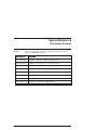
Table of Contents
.....................................................
1 950BASIC Language
1-1
1.1 950BASIC Program Structure . . . . . . . . . . . . . . . . . . . . . . 1-1
1.2 Program Sections . . . . . . . . . . . . . . . . . . . . . . . . . . . . . 1-2
1.3 ‘Main’ program, Subroutines, Functions, and Interrupt Handlers . . 1-7
1.4 Language definition . . . . . . . . . . . . . . . . . . . . . . . . . . . 1-10
1.5 Statements . . . . . . . . . . . . . . . . . . . . . . . . . . . . . . . . 1-14
1.6 Built-In Functions . . . . . . . . . . . . . . . . . . . . . . . . . . . . 1-27
1.7 Expressions . . . . . . . . . . . . . . . . . . . . . . . . . . . . . . . . 1-29
1.8 Function Invocation . . . . . . . . . . . . . . . . . . . . . . . . . . . 1-32
1.9 Arrays and Function Parameter Lists . . . . . . . . . . . . . . . . . 1-34
1.10 PACLAN . . . . . . . . . . . . . . . . . . . . . . . . . . . . . . . . 1-38
1.11 Modbus . . . . . . . . . . . . . . . . . . . . . . . . . . . . . . . . . 1-41
1.12 Allen-Bradley DF-1 Communications . . . . . . . . . . . . . . . . 1-47
1.13 Cam Profiling . . . . . . . . . . . . . . . . . . . . . . . . . . . . . . 1-51
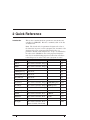
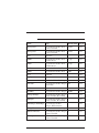
2 Quick Reference of 950BASIC Instructions
2-1
3 950BASIC Instructions (in Alphabetical Order)
3-1
Appendix A
A-1
Index
MA950-LR
Rev F
1 950BASIC Language
In this chapter
This chapter describes the overall structure of a 950BASIC
program, and the elements of the 950BASIC language. Topics
covered are:
• scope
• program structure
- setup parameters
- global variables, constants and aliases
- ‘main’ program, subroutines, functions and interrupt
handlers
• language description
-
lexical conventions
identifiers
data types
constants
statements
built-in functions
pre-defined variables
expressions
function invocation
$include
arrays and parameter lists
optimizations
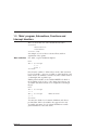
1.1 950BASIC Program Structure
Local variables
MA950-LR
The notion of ‘scope’ is a key concept in 950BASIC programs.
By ‘scope’, we mean those parts of the program in which a
particular name is ‘visible’. There are two levels of scope in
950BASIC — global and local. Variables (and constant
definitions, aliases, and so on) that are defined inside a ‘main’
definition, or a subroutine, function, or interrupt handler
definition, are considered to be ‘local’ in scope — that is, they
are visible only within that function.
1-1
Global variables
All other definitions (those occurring outside functions, for
example) are considered ‘global’ in scope — they are visible
inside main, and inside any subroutine, function, or interrupt
handler.
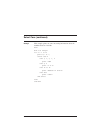
For example, consider the following simple 950BASIC
program:
dim i as integer
main
dim i as integer
for i = 1 to 10
print “the cube of ”;i;" is “;cube(i)
call increment
next i
end main
function cube(i as integer) as integer
cube = i * i * i
end function
sub increment
i = i+1
end sub
This program prints a table of the cubes of the integers from 1
to 10. The first (global) definition of ‘i’ is visible inside
subroutine ‘increment’, but ‘shadowed’ by the ‘i’ in main and
function ‘cube’. The definition of ‘i’ inside ‘main’ is local to
‘main’, and is NOT the same variable as the ‘i’ inside the
function ‘cube’, or inside the subroutine ‘increment’. These
same scope rules apply to constant definitions and aliases, as
well.
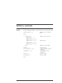
1.2 Program Sections
The major sections of a 950BASIC program are:
• setup parameter definitions
• global variables, constants, and aliases
• ‘main’ program, subroutines, functions, and interrupt
handlers
Although these sections may appear in any order, we
recommend that you keep them in the order shown, or at least
choose a single layout style and use it consistently.
1-2
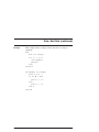
MA950-LR
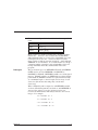
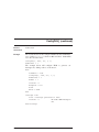
Program
template
The program below is an example of the template generated
automatically by 950IDE:
params
‘——————— Parameter Values Header ———————
‘ Drive:
SC952
‘ Motor:
R32G
‘ Performance Setting: Medium
‘ Inertia Ratio:
0
‘———————- params start ————————————
ARF0
= 150.000000
ARF1
= 750.000000
Commoff
= 0.000000
ILmtMinus
= 100.000000
ILmtPlus
= 100.000000
ItThresh
= 60.000000
Kip
= 144.513255
Kpp
= 15.000000
Kvi
= 5.000000
Kvp
= 0.059626
Polecount
= 4
BDIOMap1
= Fault_Reset_Inp_Lo
BDIOMap2
= CW_Inhibit_Inp_Lo
BDIOMap3
= CCW_Inhibit_Inp_Lo
BDIOMap4
= 0
BDIOMap5
= Brake_Out_Hi
BDIOMap6
= Fault_Out_Hi
‘———————- params end —————————————
end params
‘——————— Define (dim) Global Variables ————
‘——————— Main Program ————————————main
end main
‘——————— Subroutines and Functions ——————
‘——————— Interrupt Routines —————————-
These sections are described in greater detail in the following
paragraphs.
MA950-LR
1-3
Setup parameter
definitions
This section of the program defines the power-on default
parameters for servocontroller tuning and configuration. It is
executed immediately upon power-up, before entering ‘main’,
and before any interrupts are enabled. The section begins with
the keyword ‘params’ and ends with the keywords ‘end’ or ‘end
params’ or ‘endparams’ (this is similar to the format used to
define a subroutine or function). The only statements
permitted in this section are assignment statements of the
form:
<pre-defined variable> = <constant expression>
This section is automatically generated by 950IDE when
File|New is selected from the main menu. Ordinarily, you will
not need to modify the statements in this section — they are
automatically given optimal values based on the ‘new program’
dialog, and should not be changed unless further tuning is
necessary.
Global variables, This section contains variables, constant definitions, and alias
constants, and
expressions that are considered ‘global’ in scope — that is, they
aliases
apply everywhere in the program, unless specifically overridden
by another declaration at ‘local’ scope (inside a subroutine,
function, or interrupt handler). Global definitions may be
placed almost anywhere in the program text — between
subroutines, before or after ‘main’, and so on.
Global variables, constants, and aliases do not need to be
defined before use — the only requirement is that they be
defined at some point in the program text. So, in effect, you
may have multiple instances of the ‘global variables’ section
throughout your program. However, as a matter of good
programming style, we recommend that you keep all global
definitions in one place, preferably at or near the beginning of
your program.
1-4
MA950-LR
Variable
definitions
The format of a global variable definition is best described by
the following examples:
• dim a,b, as integer, x,y,z as float
• dim ia(3,4) as integer
• dim s1, s2 as string*80
• dim sa(5,2) as string
Line 1 declares a and b as integers, x,y, and z as floats. Line 2
declares a 3 x 4 array of integers. Line 3 declares s1 and s2 as
strings, each of length 80 Line 4 declares sa as a 5 x 2 array of
strings, each with the default length of 32 characters.
In addition, global variables can be specified as ‘nv’ to indicate
that their values are retained when power is turned off. All
other global variables are automatically initialized when the
program begins (strings are set to empty, and floats and
integers are set to 0). There are no restrictions on the
ordering of volatile vs. non-volatile user-variables. However,
we recommend that, for ease of program maintenance, you
place all non-volatile variables definitions in a single section at
the beginning of the program, and add new variables to the
end of that section.
Constant
definitions
The format of a constant declaration is:
<name> = <constant_expression>
as in
const ARRAY_SIZE = 4 * NUMBER_OF_ENTRIES
const PI_SQUARE = 3.1415926535 ^ 2
const GREETING = “Hello”
const SALUTATION = GREETING + “, world!”
const NUMBER_OF_ENTRIES = 5
MA950-LR
1-5
Names for constants follow the same rules as variable names
(see below). ‘Forward definitions’ are allowed; circular
definitions are detected and reported at compile-time.
Although it is not required, you will probably find it
convenient to adopt a convention of keeping all constants in
UPPER_CASE, so that you can easily distinguish between
constants and variables in your program.
Constant definitions are entirely ‘folded’ at compile-time. This
means that you should always feel free to write maintainable
constant expressions such as:
const LENGTH = 3
const WIDTH = 10
const AREA = LENGTH * WIDTH
The value of AREA is computed at compile-time, so your
program will NOT need to compute this at run-time, and your
program will be easier to maintain if LENGTH changes at
some future date.
Alias definitions
An alias is just what you would expect — another name for
something. Aliases allow you to define your own names for
system resources such as input / output pins. The intention is
to make it possible for you to use names that are meaningful
to you in your particular application.
The format of an alias expression is:
alias <name> = <expression>
For example, the following alias defines application-specific
uses of input # 1:
alias CONVEYOR_IS_RUNNING = (inp1=0)
alias CONVEYOR_IS_STOPPED = (inp1=1)
if CONVEYOR_IS_RUNNING then print
“running” else print “stopped”
An alias is much more powerful than a constant. Constant
expressions are computable at compile-time, while an alias has
a value that is only known (in general) at the time it is used.
For this reason, aliases should be used with care — too much
aliasing can make it very difficult for you to understand your
program.
1-6
MA950-LR
1.3 ‘Main’ program, Subroutines, Functions and
Interrupt Handlers
These sections share the same fundamental structure:
<section>
<declarations>
<statements>
<section end>
An example of each of these sections follows, with an
explanation of key points.
‘Main’ definition
For ‘main’, a typical definition might be
main
dim i as integer
i = 1
print i
end main
Note that the variable ‘i’ defined above in the ‘dim’ statement
is a local variable — it is not accessible to other functions, and
inside ‘main’, its definition overrides any other variable named
‘i’ that might exist at global scope.
Unlike global variables, local variables MUST be defined at
the beginning of the section — they must appear before any
executable statement in main. For example, the following is
illegal:
main
dim i as integer
i = 1
dim j as integer
‘this is an error!
j = i
end main
You may also define local constant definitions and aliases,
provided that, like local variables, they appear before any
executable statement. Local constant definitions override
global definitions of the same name.
MA950-LR
1-7
For example, given the following global definitions,
const N = 1
main
const N = “Hello, world!”
print N
call sub1
end main
sub sub1
print N
end sub
The program will print:
Hello world!
1
because the N visible inside ‘main’ is the constant defined
there, while the N visible to ‘sub1’ is the global constant N,
whose value is 1.
The ‘main’ program is the section of your program that will be
executed immediately after the ‘params’ section, regardless of
its position in the program text. Other functions, subroutines,
and interrupt handlers are executed according to the flow of
control defined in the program.
‘Main’ does not accept arguments, and cannot be called from
any other subroutine, function, or interrupt handler.
1-8
MA950-LR
Subroutine
definition
For a subroutine, say, ‘print_sum’, a typical definition might
be:
sub print_sum(i,j as integer)
print i+j
end sub
The arguments to this subroutine are specified as integer
variables, and are passed ‘by value’ — any assignments to these
variables will have no effect on the arguments supplied by the
caller. Subroutines are invoked by ‘call’ instructions, as in
call print_sum(3,4)
Function
definition
For a function, say, ‘sum_squares’, a typical definition might
be:
function sum_squares(i,j as integer) as integer
sum_squares = i^2 + j^2
end function
The function above returns a value of type integer. The value
of the function is assigned by assigning to the name of the
function, as if it were a variable. Note, however, that it is not
legal to use the function name as a variable on the
right-hand-side of an assignment — a function name on the
right-hand-side is always an INVOCATION of that function.
There must be at least one statement in the function that
assigns a value to the function. However, it is not possible, in
general, to detect at compile-time if that statement will
actually be executed.
Functions are invoked by name, as in
print sum_squares(3,4)
Note: This is syntactically identical to an array reference.
MA950-LR
1-9
Interrupt handler For an interrupt handler, say ‘i1hi’, a typical definition might
definition
be:
interrupt i1hi
print “interrupt occurred on input 1"
intri1hi = TRUE
end interrupt
Note that the interrupt is re-enabled by the statement ‘intri1hi
= TRUE’. A similar statement must be executed once before
the interrupt can be serviced. It is a run-time error to attempt
to enable an interrupt for which no handler has been defined.
Interrupt handlers do not return values, and cannot have
arguments. They can, however, declare local variables,
constants, and aliases, just like other subroutines.
Interrupt handlers are invoked when the 950 hardware detects
that the designated interrupt condition has been satisfied
(provided that the interrupt has been enabled).
1.4 Language definition
Lexical
conventions
950BASIC is case-insensitive. String literals are not modified,
but all other text is treated as if it was entered in upper case.
This means that the identifiers “spin”, “Spin”, and “SPIN” all
refer to the same entity.
Identifiers
Identifiers are alphanumeric, and must start with an alphabetic
character or underscore. In addition, they may include the
underscore character (‘_’) and dollar sign (‘$’). Identifiers
denote variables, functions, subroutines, and statement labels,
symbolic constants, and aliases. Identifiers can be at most 40
characters long. User-defined identifiers may not include the
period (‘.’). Use of a longer identifier is a compile-time error.
1 - 10
MA950-LR
There are several pre-defined variables that have a special
form:
predefvar
{alpha} {alnum}* ‘.’ {alnum}*
alpha
[A-Za-z_]
alnum
[A-Za-z_0-9$]
Many of these pre-defined variables have alternate spellings
without the ‘.’ character, such as index.dist and IndexDist.
Although both forms are accepted for compatibility, the latter
form is preferred, since the ‘.’ character may be used in a
future version to indicate structure members. And, although
950BASIC is case-insensitive, we recommend that you adopt a
consistent naming convention, such as IndexDist, and avoid
having indexDist, index.dist, and Indexdist in the same
program.
Data types
The pre-defined types are INTEGER, FLOAT, and STRING.
LONG may be used for INTEGER, and SINGLE or
DOUBLE for FLOAT. INTEGER variables are 32-bit signed
integers. FLOAT variables are IEEE single-precision floating
point numbers. STRING variables are represented internally
as a maximum length, a current length, and an array of ascii
characters (this means that strings may contain null
characters).
When a FLOAT result is assigned to an INTEGER variable,
or when a FLOAT argument is used where and INTEGER is
expected, the value is coerced to an integer before use.
Coercion from FLOAT to INT always rounds to the nearest
integer. For example,
1.2 rounds to 1
1.7 rounds to 2
-1.2 rounds to -1
-1.7 rounds to -2
MA950-LR
1 - 11
Scalar INTEGER and FLOAT coercion is automatically
provided for function arguments. When passing ARRAYS as
arguments, however, the types must match exactly, since
coercion could be prohibitively expensive at run-time
String assignment is checked at run-time — an attempt to
copy a string to a destination that is too small will result in a
run-time error. String indexing is 1-origin. For example,
mid$(“abc”,1,1) returns the string “a”.
STRING variables have a firmware-imposed maximum length
of 230 characters, and a default maximum length of 32
characters. They may be assigned a different maximum length
by declaring them to be of type STRING*n where n is a
positive integer between 1 and 230 (inclusive).
Arrays of any of the pre-defined types can be declared. Arrays
have a maximum rank of 4 dimensions. The upper bound of
each dimension has no compiler-defined limit; however,
because of the limited data space of the controller, there is a
logical upper bound which depends on the controller model.
Array indexing is 1-origin. The indices in each dimension
range from 1 to the upper bound of the dimension. Every
reference to an array element is checked at run-time — any
attempt to reference beyond the bounds of the array causes a
run-time error.
New types can not be defined (there is no support for the
TYPE construct of QuickBasic).
Literal
constants
1 - 12
String constants begin and end with the double-quote
character (‘"’). They can not extend past the end of the input
line. Any printable ASCII character may appear in a string
constant. An attempt to generate a string literal with
non-ASCII characters will cause a compile-time error.
Although no check is made to verify that non-ASCII strings
are not created at run-time, you should avoid doing so,
because attempting to print non-ASCII characters at run-time
may confuse the Integrated Development Environment’s
debugger.
MA950-LR
Decimal integer
constants
Decimal integer constants are a string of decimal digits with no
decimal point. A leading ‘-’ sign is optional (and is parsed as a
unary minus). For example,
1
-1
314159
are all valid decimal constants.
Hexadecimal
constants
Hexadecimal constants are denoted by a leading ‘&H’ or ‘&h’,
and can not have a sign or decimal point. Hexadecimal
constants are composed from the set [0-9A-Fa-f]; upper and
lower case may be mixed. For example,
&h00ff
&HFF00
&H1234abcd
are all valid hexadecimal constants.
Note: Octal and binary constants are not supported.
Floating-point
constants
Floating-point constants are specified in fixed-point or
mantissa-exponent notation. A floating-point constant consists
of one of the following.
Note: “.” is not a legal floating-point constant, by design.
MA950-LR
digit
[0-9]
optsign
‘+’ | ‘-’ | /* nothing */
fixed
optsign {digit}+ ‘.’ {digit}*
optsign ‘.’ {digit}+
exp
fixed ‘e’ optsign {digit}+
float
fixed | exp
1 - 13
For example:
0.1
.1
-.1
-0.1
3.14159E-6
-1.0E6
are all valid floating point constants.
1.5 Statements
Statements are separated by a new line (CR-LF) or a colon
(‘:’).
The statements of the language are:
AbortMotion
AbortMotion stops motor motion while allowing continued
program execution. Deceleration is determined by the motor
torque capability in conjunction with the current limit
parameters.
Alias
Alias <name> = <expression>
Create an alias for an identifier (Note: not just any identifier).
“alias” can be a pre-defined variable or another alias; “id”
must be a legal variable name. Note: You cannot create an
alias for an array element.
Like Const definitions, Alias definitions can be made to
identifiers not yet defined. Circular definitions are not allowed.
Note: Any duplicate definition of an identifier in the same scope
is illegal. However, a local definition can shadow a definition
from the global scope. Note that using a single identifier to denote
two different objects is disallowed, i.e. you can’t have both a label
and a variable named “all_done”.
Like constant, variable, and function declarations, Alias
declarations made in the global scope are imported into all
functions (including the main function).
1 - 14
MA950-LR
Example
Alias speed = motor.speed
‘save some keystrokes
Beep
Sends the ASCII character &h7 to the serial port.
Call
CALL sub[(arg1, arg2, ...)]
“sub” is the name of a subroutine. The current program
counter is saved, sub is invoked, and when sub finishes (by
reaching an “exit
sub” or “end sub” statement) control is
returned to the statement logically following the Call.
A subroutine is essentially a function with no return value.
The parameter passing conventions followed by subroutines
are the same as those followed by functions. (See below for
details.)
Cls
This statement transmits 40 line feed characters (ASCII code
= 10) to the serial port. Cls clears the display of a terminal.
Const
Const name = x
Declares symbolic constants to be used instead of numeric
values. Forward references are allowed, but circular
references are not supported.
CONST x = y + 2
CONST y = 17
unsupported
CONST x = y + 2
CONST y = x - 2
Like alias, variable, and function declarations, Const
declarations made in the global scope are imported into all
functions (including the main function).
MA950-LR
1 - 15
Dim
Dim var1 [, var2 [...]] as type [NV]
All variables must be declared. Local variables must be
declared in the function before use. Global variables can be
defined in the module after use in a function (as can
functions).
The NV specifier can be used on a Dim statement in the
global scope, or in the main function, or a Static statement in
function scope.
Variables in the global scope are automatically imported into
functions and subroutines. Variables in function scope
(including
inside the main function) are not accessible in
other functions.
Arrays can not be assigned directly; i.e., the following is not
allowed:
DIM X(5), Y(5) AS INTEGER
X = Y
Instead, a loop is needed:
DIM X(5), Y(5), I AS INTEGER
FOR I = 1 to 5
X(I) = Y(I)
NEXT I
Exit
Exit {{Sub|Function|Interrupt|For|While}]
Exits the closest enclosing context of the specified type. It is a
compile-time error to EXIT a construct that is not currently in
scope.
1 - 16
MA950-LR
For...Next
For loop_counter = Start_Value To End_Value
[Step increment]
...statements...
Next
If step increment is not specified, uses 1 as the step increment.
If step increment is positive, continues while the value of
End_Value. If step increment is negative, continues while the
value of var = limit.
Note: The loop index variable must be a simple identifier, not an
array element or a pre-defined variable, and must be a numeric
variable (integer or float).
The semantics of a ‘for’ loop are defined in terms of the
following
transformation:
FOR var = init TO limit STEP delta
stlist
NEXT var
becomes:
var = init
delta_val = delta
limit_val = limit
test:
IF delta_val 0 AND var limit_val THEN
GOTO done
ELSEIF delta_val 0 AND var limit_val THEN
GOTO done
ENDIF
stlist
var = var + delta_val
GOTO test
done:
...
Note: Substantially more efficient code can be generated if ‘delta’
is a constant, i.e. the default value of 1 is used, or specified as an
expression which can be evaluated at compile-time.
MA950-LR
1 - 17
Function
Function function-name [(argument-list)] as
function-type
...statements...
End Function
On function entry, all local variable strings are “” and all
numeric locals are zero (including all elements of local arrays).
If the function takes no arguments, the paramlist should be
omitted. An empty paramlist is illegal.
The value returned from the function is specified as in
QuickBasic, by assigning to an identifier with the name of the
function. For example,
FUNCTION cube(x AS FLOAT) AS FLOAT
cube = x * x * x
END FUNCTION
Arguments are passed by value.
Note: Arrays can not be returned by a function. Arrays passed to
a function are passed by value.
If the return value is not set, a runtime error condition is
generated (which can be caught with ON ERROR).
1 - 18
MA950-LR
Array actuals must conform with formals to the extent that
they have the same number of dimensions, and EXACTLY the
same type. The size of each dimension is available to the
function through the use of local constants that are bound on
function entry. For example:
FUNCTION sum(x(N) AS INTEGER) AS INTEGER
DIM i, total AS INTEGER
sum = 0
FOR I = 1 TO N
total = total + x(i)
next
sum = total
END FUNC
This function exploits the fact that the variable N is
automatically
assigned a value when the function is called,
and that value will be
the extent of the array that was
passed on that invocation. The variable N is a read-only
variable in this context — attempts to write to N cause
compile-time errors. Note that we also rely on the fact that
the local variable ‘total’ is automatically initialized to 0 upon
function entry.
GoAbs
GoAbs (Go Absolute) causes the motor to move to the
position specified by TargetPos. This position is based on a
zero position at electrical home.
The motor speed follows a velocity profile as specified by
AccelType, AccelRate, and DecelRate . Direction of travel
depends on current position and target position only (DIR has
no effect).
Note: The program does not wait for GoAbs completion. After
the program initiates this move it immediately goes to the next
instruction.
Variables may be changed during a move using UpdMove.
MA950-LR
1 - 19
GoHome
GoHome moves the motor shaft to the electrical home
position (Position = 0).
The motor speed follows a velocity profile as specified by
AccelRate, RunSpeed, and DecelRate.
Note: The program does not wait for GoHome completion. After
the program initiates this move it immediately goes to the next
instruction.
GoHome performs the same action as setting TargetPos to
zero and executing a GoAbs function.
GoIncr
GoIncr (Go Incremental) moves the motor shaft an
incremental index from the current position.
Distance, as specified in IndexDist, may be positive or
negative. The motor speed follows a trapezoidal velocity
profile as specified by AccelType, AccelRate, RunSpeed, and
DecelRate.
Note: The program does not wait for motion completion. After
the program initiates this move it immediately goes to the next
instruction.
Parameters may be changed during a move using UpdMove.
GoVel
GoVel (Go Velocity) moves the motor shaft at a constant
speed.
The motor accelerates and reaches maximum speed as
specified by AccelRate and RunSpeed, with direction
determined by DIR. Stop motion by:
• Programming AbortMotion for maximum deceleration
allowed by current limits.
• Programming RunSpeed = 0 for deceleration at rate set by
DecelRate.
Note: After the program initiates a GoVel it immediately goes to
the next instruction.
Variables may be changed during a move using UpdMove.
1 - 20
MA950-LR
Goto
Goto label
Note that a program can only Goto a label in the same scope.
Furthermore, a Goto may jump out of a For or While loop,
but not INTO one.
If...Then...Else
IF condition1 THEN
...statement block1...
[ELSEIF condition2 THEN
...statement block2...]
[ELSE
...statement block3...]
END IF
IF...THEN...ELSE statements control program execution
based on the evaluation of numeric expressions. The
IF...THEN...ELSE decision structure permits the execution of
program statements or allows branching to other parts of the
program based on the evaluation of the expression.
There are two structures of IF...THEN...ELSE statements,
single line and block formats.
$INCLUDE
$INCLUDE “inclfile”
$Include “include-file-name”
Textually include inclfile at this point in the compilation. Note
that there can be no space between “$” and “include”, and
that the “$include” directive must start at the beginning of the
line.
MA950-LR
1 - 21
Input
Input [prompt-string][,|;]input-variable
Input reads a character string received by the serial
communications port, terminated by a carriage return.
As an option, the “prompt” message is transmitted when the
Input statement is encountered. If the prompt string is
followed by a semicolon, then a question mark will be printed
at the end of the prompt string. If a comma follows the prompt
string, then no question mark will be printed.
Interrupt ... End
Interrupt
Interrupt {Interrupt-Source-Name}
..program statements...
End Interrupt
As per manual, except that interrupt handlers may now be
located anywhere in the program text (e.g., before main).
Laninterrupt
Laninterrupt ‘[‘axis‘]’
Laninterrupt invokes an interrupt to the PacLAN controller
specified by [AXIS#].
Note: This command is only available with PacLAN controllers.
On Error Goto
On Error Goto Error-Handler-Name
or
On Error Goto 0
When a firmware runtime error condition takes place,
‘Error-Handler-Name’ is called, the error handler is
de-installed, and an internal flag (in-error-handler) is set. Any
subsequent runtime error (including attempting to set the
error handler, or return from the On Error handler) causes an
immediate Stop.
On Error Goto 0 disables the current On Error handler; if an
error occurs when no error handler is installed, Stop is
invoked.
1 - 22
MA950-LR
Pause( )
Pause(Pause_Time) causes the program to pause the
amount of time specified by the Pause_Time argument. The
motion of the motor is not affected.
Note: This implementation differs from the SC750.
Print
Print expression1 [ [,;] expression2 ] [;]
Print a list of expressions, separated by delimiters. Any number
of
delimiters (including zero) can appear before or after
the list of expressions. At least one delimiter must appear
between each pair
of expressions in the printlist.
Note: There need be no expressions at all.
Examples
PRINT
PRINT
PRINT
PRINT
end
PRINT
Restart
‘ print a newline
,
‘ advance a single tab stop
a,b ‘ print a and b, tab between
a,b,‘ print a and b, tab between and at
,,,x,,,
‘ tab tab tab x tab tab tab
Restart clears the run time error variables and causes program
execution to start again from the beginning of the program.
Any Interrupts, Subroutines, WHEN statements or loops in
process will be aborted. This statement is used to continue
program execution after a Run Time Error Handler or to
abort from WHEN statements without satisfying the condition.
Note: Restart does not cause the data area to be cleared or in
itself change any program or motion variables.
MA950-LR
1 - 23
Select Case
Select Case test-expression
Case expression-list1
...statement block1...
Case expression-list2
...statement block1...
Case expression-list3
...statement block1...
Case Else
...else block...
End Select
test-expression must evaluate to an INTEGER or FLOAT
value.
expression-list1 is a non-empty list of case-defn, separated by
commas.
There can be at most one Case Else, and if present, it must
appear as the last case. It will be selected only if all other tests
fail.
case-defn can be any of the following:
expr
expr TO expr
(tests inclusive (closed range))
IS relop expr
(<, ≤, =, ≥, > )
IS expr
(equiv to “IS = expr”)
Note: Select-case statements where the case-defn expressions are
composed solely of integer constants will be evaluated much more
quickly at run-time. (Cases involving variables must be
transformed to logically equivalent if-then-else statements.)
1 - 24
MA950-LR
Static
Static var1 [, var2 [...]] as type
The Static statement may be used only inside a function
definition. It declares variables that maintain their values
across function invocations.
Stop
Stop stops the execution of the program.
Sub...End Sub
Sub [argument-list]
...body of the sub-procedure...
End Sub
Declare a subroutine. Invoked via Call. Optionally takes
arguments. As with Function, it is illegal to provide an empty
parameter list (‘()’) if the subroutine takes no parameters.
Swap
Swap x, y
Swaps the values of the variables. The types of the two
variables must be the same. Does not work on arrays; does
work on strings.
UpdMove
MA950-LR
UpdMove (Update Move) updates a move in process with new
variables. This allows you to change motion “on the fly”
without having to stop motion and restart the motion function
again with new variables.
1 - 25
When
When when-condition , when-action
When is used for very fast output response to certain input
conditions. You specify the condition and action. Upon
encountering the When, program execution waits until the
defined condition is satisfied. Then the program immediately
executes the action and continues with the next line of the
program.
The When statement provides latching of several variables
when the When condition is satisfied. These variables are:
WhenEncpos
WhenRespos
WhenPosCommand
WhenTime
WhenPosition
The software checks for the defined condition every 0.5
millisecond and performs the action within 0.5 millisecond of
condition satisfaction.
While...Wend
While condition
...statement block...
Wend
While...Wend tells the program to execute a series of
statements as long as an expression after the While statement
is true.
If the expression is true, then the loop statements between
While and Wend are executed. The expression is evaluated
again and if the expression is still true, then the loop
statements are executed again. This continues until the
expression is no longer true. If the expression is not true the
statement immediately following the Wend statement is
executed.
1 - 26
MA950-LR
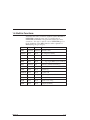
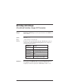
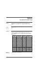
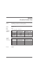
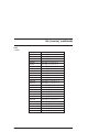
1.6 Built-in Functions
A function that takes a numeric argument (either FLOAT or
INTEGER) returns the same type. Coercion between
INTEGER and FLOAT is not performed unless necessary.
(notation — the args ‘n’ and ‘m’ refer to INTEGER types, as
in the definition of the MID$ function, whose signature is
MID$(string, integer, integer)
MA950-LR
Name
Args
Return
Semantics
ABS
numeric
numeric
absolute value
ATAN
float
float
arc tangent (radians)
CINT
numeric
int
truncate (round to nearest int)
COS
float
float
cosine
EXP
float
float
e ^ arg, arg 88.02969 (o/w overflow)
FIX
numeric
int
truncate (round toward zero)
INT
numeric
int
truncate (round towards -INFINITY)
LOG
float
float
natural log
LOG10
float
float
log base 10
SGN
numeric
integer
sign of argument: -1, 0, 1
SIN
float
float
sine (radians)
SQR
float
float
square root of arg
TAN
float
float
tangent (radians)
1 - 27
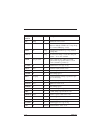
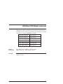
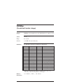
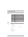
String
function
Description
ASC
string
int
ASCII code for 1st char
CHR$
int
string
One-character string containing the
character with the ASCII code of arg. If arg
255, returns CHR$(arg % 256).
HEX$
int
string
printable hexadecimal rep of arg (without
leading &H)
string
one-character string, read from serial port.
returns “” if no char available
INKEY$
INSTR
[pos],str1,str2
int
index of str2 in str1, or 0 if not found.
optional first arg specifies where to start
search (defaults to position 1)
LCASE$
str
str
returns lower-case copy of arg
LEFT$
str,n
str
returns n leftmost chars of str
LEN
str
int
returns length of str in bytes
LTRIM$
str
str
trim leading spaces
MID$
str,n[,m]
str
returns substring starting at position n [for
up to to m bytes].
OCT$
n
str
octal string representation of arg
RIGHT$
str,n
str
rightmost n chars of str
RTRIM$
str
str
trim trailing spaces
SPACE$
n
str
returns a string of n spaces
STR$
n
str
decimal string representation of str
str
return n copies of first char of str
STRING$ n,ch
str
return n copies of char
TRIM$
str
str
trim leading AND trailing spaces
UCASE$
str
str
returns upper-case copy of arg
VAL
str
numeric returns numeric value of str
STRING$
1 - 28
n,str
MA950-LR
Pre-defined
variables and
commands
The 950BASIC language is augmented by a set of ‘pre-defined
variables’, whose purpose is to set motor-specific control
parameters, and by a set of ‘pre-defined commands’, whose
purpose is to control the motor.
For example, AccelRate, DecelRate, and RunSpeed are
typically used to set the acceleration rate, deceleration rate,
and commanded motor speed for the next commanded move:
AccelRate = 1000.0
DecelRate = 1000.0
RunSpeed = 500.0
GoVel
The program fragment above sets up the relevant motion
parameters, and commands the motor to move in velocity
mode.
You cannot create variables (or function names, etc.) that
shadow the pre-defined ones. For a complete list of
pre-defined variables and commands, refer to the detailed
Language Reference section in this manual.
1.7 Expressions
Arithmetic
expressions
Arithmetic expressions (expressions involving INTEGER and
FLOAT values) can use the following operators. Operators
higher in the table have greater precedence than those below:
Numeric
Operators
Operator
MA950-LR
Assoc
Name
right
exponentiation
-
right
unary minus
*, /
left
mult, div
MOD
left
modulo
+, -
left
add, sub
1 - 29
Logical
Operators
Operator
Assoc
Explanation
=, < >, ≥, ≤, <, >
left
the usual
NOT, BITNOT
right
not, boolean not
AND, BITAND
left
and, boolean and
OR, BITOR,
XOR, BITXOR
left
or, boolean or, xor, boolean
xor
Logical expressions (as, for example, in the condition of an ‘if’
statement) may also use these operators. Strings may also be
concatenated with the ‘+’ operator. Logical expressions may
be formed from strings, using the comparison operators, NOT,
AND, OR, and XOR, with the meaning of an empty string
being FALSE, and a non-empty string being TRUE.
Integer values are coerced to floating point values as needed.
Floating point values are rounded when coerced to integer
values.
Note: This implementation differs from the SC750 which
truncated floating point values.
As with QuickBasic, logical operators are NOT
short-circuiting, i.e., when executing the code.
if a(x) or b(y) or c(z) then ...
if a(x) is true, b(y) and c(z) are still invoked.
1 - 30
MA950-LR
The BITxxx boolean operators are provided to support bitwise
operations on integer values. They operate quite differently
from their logical equivalents. For example:
‘2 and 1’ has the value -1 (TRUE, since each operand is ‘true’),
but
‘2 bitand 1’ has the value 0 (since no matching bits are 1).
Similarly,
‘3 or 4’ has the value -1 (TRUE since at least one operand is
not FALSE),
while
‘3 bitor 4’ has the value 7 (the three lsb’s are set).
Remember that relational and logical operators return
numeric values — 0 for FALSE and -1 for TRUE. Any value
not equal to FALSE is considered to be logically equivalent to
TRUE for purposes of the logical operators.
It is syntactically incorrect to code:
DIM a, b, c, x AS INTEGER
x = a < b < c
MA950-LR
1 - 31
String Operators
Operator
Assoc
Name
left
string concatenation
<, >, ≤, ≥
nonassoc
string comparisons (see
below)
=, <>
nonassoc
string comparisons (see
below)
There is no implicit coercion between strings and numeric
types.
String comparison is case-sensitive. Relative comparisons are
made using ASCII lexical ordering. The empty string sorts
before all other strings.
String comparison operators are non-associative because they
evaluate to a numeric value, i.e. it makes no sense to say
“a$ = b$ = c$”. It is sensible to say “x = a$ = b$”; x is
assigned the value TRUE if a$ is the same as b$, and false
otherwise.
1.8 Function Invocation
A function invocation is denoted in the following manner:
var = func(arg1, arg2, ..., argn)
The arguments are passed by value. i.e., modifications made to
the formal parameters inside a function are not reflected in the
actuals.
Arrays are also passed by value to functions. Arrays can not be
returned by a function.
1 - 32
MA950-LR
A function of no arguments is invoked by using the function
name alone. For example, if ‘func_none’ takes no arguments,
then
func_none
is correct, and
func_none()
is invalid.
The return value of a function may not be ignored by the
caller. If the return value of a function is regularly ignored,
the function should be rewritten as a subroutine (which is
simply a function with no return value).
$INCLUDE
The $INCLUDE directive is used to textually include one file
in another. The syntax is described above. The $INCLUDE
facility is a simple, powerful way to create a consistent family
of applications. By ‘including’ source files containing
commonly used functions, subroutines, constant definitions,
aliases, etc., you have control over the source for each
application. When you change that source, you can update
each application simply by recompiling. (See also the note
under the ‘Optimizations’ section.)
A file cannot include itself, either directly or indirectly.
Include file nesting is allowed, but limited to a pre-defined
maximum depth (currently 16).
Like the C preprocessor, the path of an include file is relative
to the directory of the included file, not the current working
directory of the compiler. Suppose, for example, the source
program is in directory C:\WORK, and includes the file
“..\H\HEADER”, and that the file HEADER includes
“COMMON”. The compiler will look for COMMON in C:\H,
not in C:\WORK.
C:\WORK
A.BAS
$INCLUDE “..\H\HEADER”
C:\H
HEADER
$INCLUDE “COMMON”
MA950-LR
1 - 33
A file may be included multiple times, which can cause
compilation errors. For example, if B.BAS includes files
MATH and INCL, and INCL also includes MATH, MATH
will be included twice, causing a compile-time error.
B.BAS
$INCLUDE “MATH”
$INCLUDE “INCL”
INCL
$INCLUDE “MATH”
1.9 Arrays and Function Parameter Lists
When an array parameter (formal) of a function or subroutine
is declared, the number of dimensions is specified, but the
extent of (number of elements in) each dimension is not
specified. This allows the programmer some freedom when
invoking such a function.
For example, a function may be defined to take a
one-dimensional array and compute the sum of the elements in
the array. A single function can be written that will take a
one-dimensional array of any size and correctly compute the
sum.
(Because 950BASIC checks array bounds at run time on each
access, there is no risk that a function will read or write
outside the bounds of the array.)
When a formal parameter to a function is an array, instead of
specifying the extent of each dimension, a list of variables is
used to both implicitly specify the number of dimensions and
to hold the extent of each dimension. These variables are
read-only; they can not be modified within the function.
1 - 34
MA950-LR
We recommend that you adopt a convention for assigning
names to placeholders. One such convention is to use the
name of the array with a numerical suffix. For example,
function f(a(a1,a2,a3) as integer) as
integer
where a1, a2, and a3 are the variables that get the extents of
the array ‘a’. The function f above would be called as follows:
dim x_array(3,4,5) as integer
dim y_array(1,2,10) as integer
print f(x_array()) + f(y_array())
In both invocations of ‘f’, the function correctly determines the
extent of each dimension of the passed array.
Remember that when passing an array to a function, the type
of the array must match EXACTLY with the type expected by
the function. Unlike scalar arguments, which are implicitly
coerced from float to int or int to float, arrays are NOT
coerced. An attempt to pass an integer array to a function
that expects a float array results in a compile-time error.
Optimizations
As mentioned in an earlier section, constant definitions are
completely ‘folded’ at the point of definition, which makes for
more efficient code. Constant expressions inside 950BASIC
statements are also folded under certain conditions. For
example, in the statement
const PI = 3.1415926535
main
print PI^2
end main
the value of PI^2 is not computed at run-time — it has
already been detected as a constant value and pre-computed
by the compiler as a single literal constant to be printed.
Similarly, the literal constant 3*4*PI in
x = 3 * 4 * PI * x
is folded at compile-time, leaving only one multiplication to be
performed at run-time.
MA950-LR
1 - 35
However, certain constant expressions will not be folded. For
example, the computation of
x = 3 * PI * x * 4
will be done at run-time, involving 3 multiplications. This is
because the analysis of constant expressions does not attempt
to exploit algebraic commutativity laws. Since the basic
arithmetic operators are ‘left associative’, you can ensure the
best performance by grouping constant factors together
towards the left (or using a new constant definition).
If a function is not referenced (transitively from MAIN, plus
any interrupt handlers), the compiler does not generate code
for it. So, you can freely $include “libraries” with code that is
not used (e.g. a comprehensive library that contains functions
supporting several possible axis configurations). Although the
compiler will still parse and type-check all of the included
source, it will not generate code that goes into the downloaded
program.
If select-case cases are all constants, much more efficient code
will be generated. If any of the cases is a variable, the
generated code will be equivalent to a string of if-then-else
statements for all of the cases.
If any of the cases is an open-ended range (e.g., ‘is 10’), or
covers a large range (e.g., ‘1 to 1000’) a fast table-lookup will
be generated. This method can several times faster than the
first method.
If all of the cases are constant, and can reasonably be grouped
into ‘locally dense subsets’, then the fastest possible code will
be generated — a binary search of dispatch tables, followed by
an indirect jump through the table. This last method can be
much faster than the first method, so if speed is a
consideration, you should keep your cases constant and ‘close
together’. (It is not necessary that cases be ‘textually’ close
together — it is only necessary that the values form a
reasonably dense set.)
1 - 36
MA950-LR
The compiler performs limited dead-code elimination based on
simple constant analysis. For example, consider the following
code
const DEBUGGING = FALSE
main
dim i, sum as integer
for i = 1 to 10
sum = sum + i
if DEBUGGING then print “partial sum is
”;sum
next i
end main
Since the value of DEBUGGING is FALSE, the compiler will
recognize that the printing of the partial sum can never
happen, and will not generate the print statement. This allows
you to place debugging code in strategic locations in your
programs, and effectively disable it when shipping a production
version (and shrink the size of the generated code, as well).
This sort of dead-code elimination also applies to functions
whose only point of reference lies in code that is eliminated.
In such cases, the functions themselves become dead-code, too,
and no code will be generated for their definitions.
The compiler will not, however, eliminate the print statement
from the following program, which is a slight variation of the
one above:
dim DEBUGGING as integer
main
dim i, sum as integer
DEBUGGING = FALSE
for i = 1 to 10
sum = sum + i
if DEBUGGING then print “partial sum is
”;sum
next i
end main
In this case, the print statement will never be executed, but the
code to implement it is still generated. This is because it’s
possible that the value of the integer DEBUGGING could be
changed by the 950’s Integrated Development Environment
Debugger at runtime, causing the print statement to be
executed!
MA950-LR
1 - 37
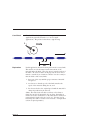
1.10 PACLAN
Introduction
PACLAN is a local area network (LAN) which provides high
speed (2.5 MBaud) inter-axis serial communication between
Pacific Scientific SC950 single-axis programmable position
controllers. The PACLAN can provide support for up to 255
SC950 controllers. Information can be passed between any
two axes on a peer-to-peer basis. This capability is supported
by specific features built into the BASIC language on the
OC950.
PACLAN connectivity is an option and is only available on the
OC950-503-01 and OC950-504-01 and OC950-603-01 and
OC950-604-01 models. Use ModelExt to determine what type
of OC950 you have.
Using PACLAN you can read and write pre-defined variables
on any other SC950 connected to the PACLAN. You can also
generate interrupts on any of those axes, causing them to
perform specific actions.
Configuration
Implementing a PACLAN network involves the following
simple steps:
• Configure each SC950 on the PACLAN with a unique
address using the address selection DIP switch on the
OC950 card.
• Connect the SC950s with RG62 coax cable, terminating it
at both ends with a 93 ohm terminator.
• Develop programs for the axes that incorporate inter-axis
communications.
Note: Please see Section 3.5 in MA950 - 0C950 Hardware and
Installation Manual for cabling and hardware information.
1 - 38
MA950-LR
Reading and
Writing
Pre-defined
Variables
PACLAN provides interaxis communication of the pre-defined
variables and PACLAN array variables. Inter-axis pre-defined
variables can be used in a BASIC program in exactly the same
manner as local pre-defined variables. The SC950 will access
the variables, over PACLAN, transparently to the user
program.
Within a program, all off-axis variable accesses require the
variable name to be appended with the axis address in square
brackets. Axis designation, with square brackets, is not
required for on-axis variable usage.
Accessing
Pre-defined
Variables Over
PACLAN
PACLAN provides read/write access to all pre-defined
variables on all SC950s connected to the PACLAN. You
should use care in writing to pre-defined variables on another
axis because extensive use of this capability can lead to
programs that are difficult to debug.
Each SC950 also contains two uncommitted variable arrays
(LANFlt and LANInt) specifically intended for inter-axis
communications. These array variables also have read-write
capability. See LANFlt( ) and LANInt( ).
Note: Attempting to read from or write to a controller that is not
present on the PACLAN will result in a run-time error on the
initiating controller. Use the pre-defined variable Status[ Axis # ]
to determine if an axis is present on the PACLAN.
Example
PACLAN can access any pre-defined variable on any other
axis. This is performed by appending the axis address in
square brackets after the variable name.
For instance, to set the variable ‘x’ equal to the value of
Velocity on axis 3, use the statement:
x = Velocity[3]
MA950-LR
1 - 39
Example
To set index distance on axis 5 equal to 10,000 counts, use the
statement:
IndexDist[5] = 10000
Pre-defined variables with an axis specifier may be used
wherever any other variables are used, with the exception of
the WHEN statement.
LANInt() and
LANFlt() Arrays
Two general purpose read/write variable arrays (one integer,
one floating point) are available for user-defined inter-axis
message passing. There are 32 elements in each array. These
arrays are essentially pre-defined variables that have no
pre-defined functionality and are thus available to you for
whatever purpose you choose.
The integer array syntax is designated as:
x = LANInt( y )[ n ]
LANInt( y )[ n ] = x
where y is the array element (1-32) and n specifies the axis
address containing the LAN array.
The floating point array syntax is designated as:
x = LANFlt( y )[ n ]
LANFlt( y )[ n ] = x
where y is the array element (1-32) and n specifies the axis
address containing the LAN array.
Again, like the other pre-defined variables, these arrays can be
used wherever any other variable can be used.
Please see LANint( ) and LANFlt( ) for additional
information.
1 - 40
MA950-LR
PACLAN
Interrupts
Interrupts can be sent from a source axis to a destination axis
using PACLAN. To send an interrupt to a program running
on another axis, use the SendLANInterrupt function. This
function allows you to specify the axis address of the program
the interrupt is being sent to. The SendLANInterrupt function
also allows you to send an integer argument along with the
interrupt.
The receiving axis must have a PACLAN interrupt handler
defined or else the SendLANInterrupt will fail. There is a
queue on each axis which allows each axis to buffer PACLAN
Interrupt requests.
Example
For instance, if axis 3 receives an interrupt from axis 5, it
automatically jumps to a PACLAN interrupt handler and starts
servicing the PACLAN interrupt. If axis 3 receives a
PACLAN interrupt request from axis 2 before it is done
servicing the request from axis 5, then it will buffer that
request and service it when it is done with axis 5. This queue
can hold 32 interrupt requests.
1.11 Modbus
Note: The following functionality applies only to OC950s with
Enhanced Firmware. Standard OC950s are are not capable of
communicating on a Modbus network.
Definition
Modbus was originally developed by Modicon as a means for
PLCs to communicate with programming terminals. It is now
widely used by many suppliers of industrial automation
equipment seeking a robust, widely supported and inexpensive
serial communications protocol.
Modbus is a serial (RS232 or RS485) communications protocol
consisting of one master and multiple slaves. The Modbus
master initiates all transactions on the Modbus network. These
transactions consist primarily of messages to read the values of
data on a slave or to write new data values to a slave. The
Modbus slaves just generate responses to messages initiated by
the master.
MA950-LR
1 - 41
An OC950 can be configured to operate as either a Modbus
master or as a Modbus slave. In either case there must be a
program running on the OC950 in order for it to communicate
on Modbus. When there is no program running on the OC950
the OC950 communicates using its native protocol.
Modbus Register There are two fundamental data types defined by Modbus: bits
and Data Types
and registers.
Bits
Bits contain one bit of information. In the Modbus address
space, bits may be located at addresses 1-9999 (0x references)
and 10001-19999 (1x references). In Modbus terminology bits
are called either coils (0x references) or inputs (1x references).
Inputs are read-only meaning that the master can read the
value of these bits, but cannot write a new value to them.
Coils are read-write.
An MMI or touchscreen could use a bit reference to read the
value of the OC950’s Moving pre-defined variable or to write a
new value to the Dir variable.
Registers
Registers contain 16 bits of information. In the Modbus
address space, registers may be located at addresses
30001-39999 (3x references) and 40001-49999 (4x references).
In Modbus terminology registers are called either Input
Registers (3x references) or Holding Registers (4x references).
Input Registers are read-only; the master can read the value of
these registers, but cannot write a new value to them. Holding
Registers are read-write.
Examples of using register references include an MMI or
touchscreen using a register reference to read the value of
Velocity or write a new value to IndexDist.
Floating Point
and 32 bit
Integer
Registers
1 - 42
There are two additional register data types which, while not
explicitly defined by Modbus, are supported by many Modbus
devices. These are 32 bit integer registers and 32 bit IEEE
floating point registers. Each of these extended types uses two
adjacent 16 bit registers to hold the 32 bit value. The OC950
supports 32 bit integers and 32 bit floating point as both a
master and as a slave. The word-order of the two adjacent 16
bit registers that are combined to form the extended type is
configurable using MB32WordOrder and MBFloatWordOrder.
MA950-LR
Using an OC950
as a Modbus
Slave
You would set up your OC950 as a Modbus slave to allow a
Modbus master, such as a touchscreen or an MMI, to read
and/or write values on the OC950. Configuring an OC950 to
operate as a Modbus slave consists of adding the following
items to your program:
1. An MBInfo Block which maps pre-defined variables and/or
user-global variables to specific Modbus addresses.
The MBInfo block contains multiple $MBMap<xxx>
statements which specify this mapping. You can use the
Modbus Map Wizard in the 950 IDE to assist you in
creating this map. There is also an example program
MBDEMO.BAS in the Examples directory
(\950win\examples) which contains a complete MBInfo
block.
2. Adding a line to set RuntimeProtocol to 2 (Modbus Slave).
You must set RuntimeProtocol to 2 to tell the OC950 to
operate as a Modbus slave. After you set this then the
OC950 will respond to Modbus messages, both reads and
writes, without any intervention from the user program.
You should keep in mind the following when configuring
an OC950 as a Modbus slave:
- the OC950 baud rate must match the master’s. See
BaudRate variable.
- the OC950 parity must match the master’s. See
RuntimeParity.
- the OC950 supports 1 start bit, 8 data bits and 1 stop bit
- the OC950 does not require or support hardware
handshaking. If the master requires it then it must be
defeated on the master.
- 255 is not a valid Modbus slave address. Setting
RuntimeProtocol to 2 with an AxisAddr of 255 will cause
a Runtime Error 38.
MA950-LR
1 - 43
Using an OC950
as a Modbus
Master
The Modbus Master functionality allows an OC950 to
communicate with one or more Modbus slaves. You would
use an OC950 as a Modbus master to communicate with a
Modicon PLC or some other device which can only operate as
a Modbus slave. As Modbus master the OC950 would initiate
all traffic on the Modbus network.
To use an OC950 as Modbus master, you just need to set
RuntimeProtocol to 3 (Modbus Master) and then use any of
the eight Modbus functions and statements which implement
Modbus master functionality. If you try to use one of these
functions or statements without first setting RuntimeProtocol
to 3 then you’ll get a Runtime Error 37.
There are four Modbus statements added to the OC950
BASIC language to allow the OC950 to operate as a Modbus
master to write data to a Modbus Slave. These are:
MBWriteBit(a, b, c)
write a bit
(0x or 1x reference)
MBWrite16(a, b, c)
write a 16 bit integer
(3x or 4x reference)
MBWrite32(a, b, c)
write a 32 bit integer
(double 3x or 4x reference)
MBWriteFloat(a, b, c)
write a float
(double 3x or 4x reference)
where, in each case:
a is the slave’s Modbus address
b is the register address where the data is to be written
c is the new data
1 - 44
MA950-LR
There are four Modbus functions added to the OC950 BASIC
language to allow the OC950 to operate as a Modbus master
to read data from a Modbus slave. These are:
x = MBReadBit(a, b)
read a bit
(0x or 1x reference)
x = MBRead16(a, b)
read a 16 bit integer
(3x or 4x reference)
x = MBRead32(a, b)
read a 32 bit integer
(double 3x or 4x reference)
x = MBReadFloat(a, b) read a float
(double 3x or 4x reference)
where, in each case:
a is the slave’s Modbus address
b is the register address containing the data we’re reading
When one of these functions or statements is executed in your
program the OC950 will send a Modbus message to the
specified slave and the wait for and process the response
message. If any error occurs while sending or receiving the
message, it will be indicated in the variable MBErr.
Modbus master statements and functions cannot be nested. If
you get an interrupt while waiting for the response to a
Modbus master message then you cannot initiate another
Modbus transaction (by executing one of the eight Modbus
functions or statements) in the interrupt service routine. If
you do so then you will generate a Runtime Error 36.
You should keep in mind the following when configuring an
OC950 as a Modbus master:
- the OC950 baud rate must match the slaves’. See
BaudRate variable.
- the OC950 parity must match the slaves’. See
RuntimeParity.
- the OC950 supports 1 start bit, 8 data bits and 1 stop bit
- the OC950 does not require or support hardware
handshaking. If a slave requires it then it must be
defeated on the slave.
MA950-LR
1 - 45
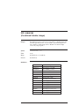
Modbus
Reference
Refer to the following items in the reference section for
additional information on Modbus:
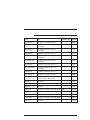
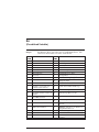
Item
Used for Master or Slave Operation?
BaudRate
Both
MB32WordOrder
Both
MBErr
Master
MBFloatWordOrder Both
1 - 46
MBInfo Block
Slave
MBMap16
Slave
MBMap32
Slave
MBMapBit
Slave
MBMapFloat
Slave
MBRead16
Master
MBRead32
Master
MBReadBit
Master
MBReadFloat
Master
MBWrite16
Master
MBWrite32
Master
MBWriteBit
Master
MBWriteFloat
Master
RuntimeParity
Both
RuntimeProtocol
Both
MA950-LR
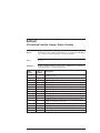
1.12 Allen-Bradley DF1 Communications Protocol
Note: The following functionality applies only to OC950s with
Enhanced Firmware. Standard OC950s are are not capable of
communicating on an Allen-Bradley Communications network.
Definition
Allen-Bradley DF1 is a communications utility based on the
DF1 peer-to-peer communications protocol. The
Allen-Bradley DF1 functionality allows the SC950 to
communicate with other devices supporting AB DF1on a
peer-to-peer basis.
The SC950 is capable of responding to messages initiated by
other devices (unsolicited commands) as well as initiating
messages to read and write registers on other devices (solicited
commands).
The SC950 support communications with the following
Allen-Bradley PLCs.
• SLC500 family of processors — both solicited and
unsolicited commands.
• PLC5 family of processors — solicited commands only (the
SC950 can initiate read/write commands, but will not
respond to read/write commands initiated by the PLC5).
Other devices supporting Allen Bradley DF1 Serial
Communications protocol may also be able to communicate
with the SC950.
Procedure
To establish Allen-Bradley DF1 communications between the
SC950 and another device:
1. The SC950 comm port (J51) must be wired to the other
device properly.
2. All the software communication settings on both devices
must match. For more detail, see ABCrc, BaudRate, and
RuntimeProtocol. In general the settings on the following
page are appropriate.
MA950-LR
1 - 47
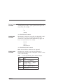
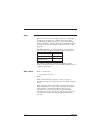
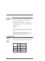
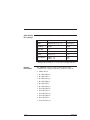
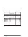
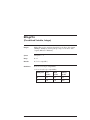
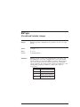
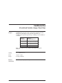
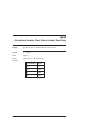
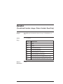
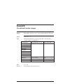
Allen-Bradley
DF1 settings
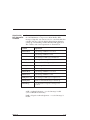
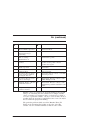
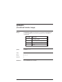
The following table lists the settings necessary for AB DF1.
SC950
Other Device
Mode
RunTimeProtocol = 5 *
Full Duplex *
BaudRate
19200
19200
Data Bits
n/a
8*
Stop Bits
n/a
1*
Parity
Parity = 0
None
Error Detect
ABCrc = 1
ABCrc = 0
CRC
BCC
* This parameter must be set to the value (setting) indicated.
Related
instructions
The 950BASIC language supports Allen-Bradley DF1
communications using the following command / functions:
• ABInfo Block
• ReadPLC5Binary
• ReadPLC5Float
• ReadPLC5Integer
• ReadSLC5Binary
• ReadSLC5Float
• ReadSLC5Integer
• WritePLC5Binary
• WritePLC5Float
• WritePLC5Integer
• WriteSLC5Binary
• WriteSLC5Float
• WriteSLC5Integer
1 - 48
MA950-LR
Allen-Bradley
DF1 Diagnostic
Variables
There are several “diagnostic” counters that are maintained by
the OC950 firmware as it processes Allen-Bradley DF1
messages. Typically, you don’t need to be concerned with these
variables, but they can be helpful in diagnosing problems in
setting up or maintaining an Allen-Bradley DF1 application.
The variables and a brief expanation are shown below:
Variable
Explanation
ABAcksRcvd
# of message ACKs I’ve received
ABAcksSent
# of message ACKs I’ve sent
ABAckTimeouts
# of messages I didn’t get an ACK for
ABDupMsgs
# of duplicate messages discarded
ABErrCount
# of times I called ab_error(..)
ABMsgsRcvd
# of messages I’ve received
ABMsgsSent
# of messages I’ve sent
ABNaksRcvd
# of message NAKs I’ve received
ABNaksSent
# of message NAKs I’ve sent
ABRspTimeouts
# of messages I didn’t get a response for
ABTXQMax
max # of outbound messages stacked up
ABUnsRsps
# of unsolicited ‘response’ messages I’ve
received
ACK = Acknowledgement — received message is valid
(correct CRC\BCC and frame).
NAK = Negative Acknowledgement — received message is
invalid.
MA950-LR
1 - 49
Allen-Bradley
DF1 Map
Wizard
This wizard will create and/or update an ABInfo block in your
program. The ABInfo block is used to map pre-defined
variables or user-defined global variables to specific ABComm
elements so that an Allen-Bradley DF1device can read or write
them. This mapping is only used when the OC950 is processing
ABComm messages initiated by another device, not when it is
initiating commands.
The wizard allows you to map OC950 variables (in
Allen-Bradley DF1 terminology) as Integer file elements
(Allen-Bradley pre-defined file # 7), or as Float file elements
(Allen-Bradley pre-defined file # 8).
Procedure
To create a mapping of an OC950 variable to an Allen-Bradley
DF1 element you:
1. Select which file (Integer or Float)
2. Specify the element address.
3. Specify the OC950 variable name.
You may also specify an optional scale factor (the default is
1.0). This scale factor is automatically applied when the
Allen-Bradley DF1 element is read or written by the
Allen-Bradley DF1 master. This is particularly useful for
mapping floating point OC950 variables into integer
Allen-Bradley DF1 elements. It can also be used for mapping
integer OC950.
Example
For example, you could map RunSpeed as a 16-bit integer
element and specify a scale factor of 10.
$ABMapInteger(1,runspeed,10.0)
Whenever the Allen-Bradley DF1 master reads integer
element 1, the OC950 would automatically multiply the
present value of RunSpeed by 10 and return this value to the
master. And when the master writes to integer element 1 the
OC950 will automatically divide the new value by 10.0 before
writing it to RunSpeed.
In this case if the value of RunSpeed was 22.5 then the Master
would read 225 for integer element 1. Similarly, if the master
wrote a value of 307 the RunSpeed would be set to 30.7.
1 - 50
MA950-LR
SLC500 to
OC950 Cable
PLC5 to OC950
Cable
To establish Allen-Bradley DF1 communications between the
SC950 and the SLC500 PLC, the following connections are
required:
SC950 (J51) DB9
SLC500 (Channel 0) DB9
2 (RS232 TX)
2 (RS232 RX)
3 (RS232 RX)
3 (RS232 TX)
5 (Common)
5 (Common)
To establish Allen-Bradley DF1 communications between the
SC950 and the PLC5, the following connections are required:
SC950 (J51) DB9
PLC5 (Channel 0) DB25
2 (RS232 TX)
3 (RS232 RX)
3 (RS232 RX)
2 (RS232 TX)
5 (Common)
7 (Common)
1.13 Cam Profiling
Note: The following functionality applies only to OC950s with
Enhanced Firmware. Standard OC950s are are not capable of
cam profiling.
Definition
In the 950, a ‘cam’ is a cyclic, generally non-linear relationship
between master encoder position and slave (motor) position.
That is, the relationship between slave counts and master
counts is no longer a constant ratio, but changes as a function
of master counts. As in electronic gearing, once a ‘cam’ has
been made active, the program no longer needs to do anything
special to maintain it - the motion profile is repeated
indefinitely until the cam is deactivated.
In camming terminology, a master is typically an external
encoder. The encoder is wired into the SC950 encoder input
port (connector J4 pins 21-24). It is also possible to use the
SC950’s virtual (internal) encoder.
MA950-LR
1 - 51
Procedure
To use a cam profile on the SC950, you must perform the
following three steps:
1. Declare the cam. See $DeclareCam.
2. Create the cam profile. See CreateCam.
3. Activate the cam profile. See ActiveCam.
Related
variables
1 - 52
CamMaster
specifies the source of the input to the cam
table for cam profiling.
CamCorrectDir
specifies the direction of the correction
move that is done when a new cam table
is activated (by setting ActiveCam = n).
Addpoint( )
adds the specified “point” (master position
and corresponding slave position) to the
cam table that is being created.
MA950-LR
Cam Wizard
The CamWizard is designed to solve a large class of
applications generally referred to as “cut to length”
applications. The picture below shows a typical setup:
r
Knife
M2 M3
M5
Explanation
In this application, material is being fed beneath a rotary knife.
The master encoder measures forward movement of the
material under the knife. The slave motor controls rotation of
the knife. In order for this to work properly, the slave motor
must be controlled (as a function of master encoder counts) so
that the blade of the rotary knife:
1. Stays out of the way until the proper amount of material
has passed
2. Accelerates so that the speed of the knife matches the
speed of the material during the cut, and
3. Decelerates back to the original speed until the material is
almost in position for the next cut.
(Note: The rotary knife will either accelerate or decelerate to
match the speed of the material in the cut phase, depending on
whether or not the circumference of the rotary knife is less than or
greater than the length of the piece to be cut. You may need to
interchange the terms ‘accelerate’ and ‘decelerate’, or simply think
of them as signed quantities.)
MA950-LR
1 - 53
950BASIC’s AddPoint statements specify a cam profile as a
mapping from master position to slave position. But the
problem as stated above refers to relative velocities and
accelerations, and it’s not always clear how to get from velocity
and acceleration to position.
The CamWizard was designed to make such applications easy
to implement. The only things you need to provide are:
• the number of master counts corresponding to the length of
material to be cut,
• the number of slave counts corresponding to one complete
rotation of the knife, and
• the ratio of slave counts to master counts during the ‘cut’
phase of the cycle.
Once you have provided these three pieces of information, the
CamWizard will automatically:
• generate code to declare a cam table of the correct size,
• generate a subroutine to create the cam table, and
• generate a subroutine to activate the cam.
1 - 54
MA950-LR
Example
In general, you can create a cam to approximate any
continuous function, but the CamWizard cannot help you with
it. The basic technique is to develop a 950BASIC expression
(or function) that defines the slave position as a function of
master position, and use it to generate a series of AddPoint
statements at appropriate master position intervals.
The following example shows how to create a cam profile that
looks like this:
MA950-LR
1 - 55
const MC = 10000
‘ master counts in total cycle
const NPOINTS = 501
‘ number of points in cam profile
const pi = 3.1415926535
‘ tuning constants for nice motion
const k = 0.69314718/100
const w = 1/(7.5*pi)
‘—————————————————————
$declarecam(2,NPOINTS)
‘—————————————————————
‘ sub ActivateCam_2
sub activatecam_2
Enable = 1
EncPosModulo = MC
PosModulo = MC
EncPos = 0
ActiveCam = 2
end sub
‘—————————————————————
‘ sub CreateCam_2
‘ This code creates a cam whose profile is an exponentially
‘ damped sine wave.
sub CreateCam_2
dim m,s as float
dim i as integer
CreateCam(2)
for i = 0 to NPOINTS-1
‘ master position
m = i*(MC/(NPOINTS-1))
‘ computed slave position
s = (1/exp(1.5*k*i)) * sin(2*pi*w*i)
addpoint(m,2000*s)
next i
end createcam
end sub
‘————————————————————-
1 - 56
MA950-LR
Program
(cont’d)
‘ Generate a cam that does exponentially-damped sinusoidal
‘ motion, and activate it. Please note that since we’re computing
‘ 500 points of slave profile here, several seconds will elapse
‘ during the calculation of the cam table.
main
enable = 1
vmdir = 0
vmrunfreq = 1000
vmgovel
print “Creating cam 2"
call CreateCam_2
call ActivateCam_2
print “Cam 2 is active now”
end main
MA950-LR
1 - 57
Virtual encoder
(virtual master)
The virtual encoder is an internal count generator that can be
used as the input to the cam. It is controlled very much like
the profile generator that is used to control the motion of the
motor. The pre-defined variables and statements associated
with the virtual encoder are listed below:
Move
parameters
vmDir
specifies direction for vmGoVel
vmIndexDist
specifies distance for vmGoIncr
vmRunFreq
specifies speed (frequency) for vmGoIncr
and vmGoVel
vmGoIncr
executes incremental move
vmGoVel
executes velocity move
vmUpdMove
progress
updates move parameters on move in
vmStopMotion
stops motion
vmEncpos
gives the value of the internal counter
vmMoving
indicates whether a move is in progress
Move
statements
Other variables
The virtual encoder can be used as the input to the cam either
alone (as a virtual master) or in combination with the actual
encoder (Encpos) to add an offset to the master position. This
functionality is controlled by the variable CamMaster.
1 - 58
MA950-LR
2 Quick Reference
Introduction
This section contains functions, parameters, statements and
variables for 950BASIC. Below is a summary table of the list
of instructions.
Note: The default value for parameters designates the value of
the instruction at power on and at program start. A numeric value
designates the power on/program start default value of a
parameter. Default values designated by “set up” are initialized to
the value in the PARAMS section of the program. Parameters
may also be modified during program execution but will always
retain their power on value at the start of program execution.
Name
Type
Default Value
ABCrc
Pre-defined Variable, Integer
3-2
ABErr
Pre-defined Variable, Integer
3-3
ABInfo...End
Page #
3-4
$ABMapFloat()
Statement
3-6
$ABMapInteger()
Statement
3-7
AbortMotion
Statement
3-8
Abs()
Function
3-9
AccelGear
Pre-defined Variable, Integer 16,000,000 rpm/sec 3-10
AccelRate
Pre-defined Variable, Integer 10,000 rpm/sec
3-12
ActiveCam
Pre-defined Variable, Integer
3-13
AddPoint()
Statement
3-15
ADF0
Pre-defined Variable, Float
1,000 Hz
3-17
ADOffset
Pre-defined Variable, Float
0 volts
3-18
Alias
Statement
3-19
AnalogIn
Pre-defined Variable, Float,
Status Variable, Read Only
3-20
MA950-LR
2 - 1
Name
Type
Default Value Page #
AnalogOut1
Pre-defined Variable, Float,
Control Variable
0 volts
3-21
AnalogOut2
Pre-defined Variable, Float,
Control Variable
0 volts
3-22
And
Operator
ARF0
Pre-defined Variable, Float,
NV Parameter
set up
3-24
ARF1
Pre-defined Variable, Float,
NV Parameter
set up
3-25
ARZ0
Pre-defined Variable, Float
0 Hz
3-26
ARZ1
Pre-defined Variable, Float
0 Hz
3-27
Asc()
Function
3-28
Atan()
Function
3-29
Autostart
Pre-defined Variable, Integer
AxisAddr
Pre-defined Variable, Integer, 255
Read-Only
3-31
Band
Operator
3-32
BaudRate
Pre-defined Variable, Integer
BDInp1-BDInp6
Pre-defined Variable, Integer,
Status Variable, Read Only
3-34
BDInputs
Pre-defined Variable, Integer,
Status Variable, Read-Only
3-35
3-23
0
19200
BDIOMap1-BDIOMap6 Pre-defined Variables,
Integer, NV Parameter
3-30
3-33
3-36
BDLgcThr
Pre-defined Variable, Integer
0
3-38
BDOut1-BDOut6
Pre-defined Variable, Integer, 1
Control Variable
3-39
BDOutputs
Pre-defined Variable, Integer, 63
Control Variable
3-40
2-2
MA950-LR
Name
Type
Beep
Statement
BlkType
Pre-defined Variable, Integer
Bnot
Operator
3-43
Bor
Operator
3-44
Brake
Pre-defined Variable, Integer,
Mappable Output Function,
Read-Only
3-45
Bxor
Operator
3-46
Call
Statement
3-47
CamCorrectDir
Pre-defined Variable, Integer
2
3-48
CamMaster
Pre-defined Variable, Integer
0
3-50
CamMasterPos
Pre-defined Variable, Integer,
Read Only
3-51
CamSlaveOffset
Pre-defined Variable, Integer,
Read Only
3-52
CCDate
Pre-defined Variable, Status
Variable, Read Only
factory
3-53
CCSNum
Pre-defined Variable, Integer,
Status Variable, Read Only
factory
3-54
CcwInh
Pre-defined Variable, Integer
Ccwot
Pre-defined Variable, Integer
Chr$()
Function
3-57
Cint()
Function
3-58
Cls
Statement
3-59
CmdGain
Pre-defined Variable, Float
MA950-LR
Default Value Page
#
3-41
2
3-42
3-55
0
0.5
3-56
3-60
2 - 3
2-4
Name
Type
Default Value
Page #
CommEnbl
Pre-defined Variable, Integer,
Control Variable
1
3-61
CommOff
Pre-defined Variable, Float,
NV Parameter
set up
3-62
CommSrc
Pre-defined Variable, Integer
0
3-63
ConfigPLS()
Statement
3-64
Const
Statement
3-66
Cos()
Function
3-67
CountsPerRev
Pre-defined Variable, Integer
CreateCam()
Statement
3-69
CwInh
Pre-defined Variable
3-71
Cwot
Pre-defined Variable
3-72
DecelGear
Pre-defined Variable, Integer
16,000,000
rpm/sec
DecelRate
Pre-defined Variable, Integer
10,000 rpm/sec 3-74
$DeclareCam()
Statement
3-75
Dim
Statement
3-76
Dir
Pre-defined Variable, Integer
0
3-77
DM1F0
Pre-defined Variable, Integer
1,000 Hz
3-78
DM1Gain
Pre-defined Variable, Float
0.6667
3-79
DM1Map
Pre-defined Variable, Integer
9
3-80
DM1Out
Pre-defined Variable, Float,
Status Variable, Read-Only
DM2F0
Pre-defined Variable, Float
1,000 Hz
3-82
DM2Gain
Pre-defined Variable, Float
2.0
3-83
4096
3-68
3-73
3-81
MA950-LR
Name
Type
Default Value
Page #
DM2Map
Pre-defined Variable, Integer
1
3-84
DM2Out
Pre-defined Variable, Float,
Status Variable, Read-Only
Enable
Pre-defined Variable, Integer
Enabled
Pre-defined Variable, Integer,
Read-Only
EnablePLS0EnablePLS7
Pre-defined Variable, Integer
EncFreq
Pre-defined Variable, Float,
Status Variable, Read-Only
EncIn
Pre-defined Variable, Integer
1024
3-90
EncInF0
Pre-defined Variable, Float
800,000
3-91
EncMode
Pre-defined Variable, Integer
0
3-93
EncOut
Pre-defined Variable, Integer
1024
3-94
EncPos
Pre-defined Variable, Integer
EncPosModulo
Pre-defined Variable, Integer
End
Statement
3-97
Err
Pre-defined Variable
3-98
Exit
Statement
3-100
Exp()
Function
3-101
ExtFault
Pre-defined Variable, Integer,
Status Variable
3-102
Fault
Pre-defined Variable, Integer,
Mappable Output Function
3-103
FaultCode
Pre-defined Variable, Integer,
Status Variable, Read-Only
3-104
MA950-LR
3-85
0
3-86
3-87
0
3-88
3-89
3-95
0
3-96
2 - 5
Name
Type
Default Value
Page #
FaultReset
Pre-defined Variable, Integer,
Mappable Input Function
0
3-106
Fix()
Function
3-107
For...Next
Statement
3-108
Function
Statement
3-109
FVelErr
Pre-defined Variable, Float,
Status Variable, Read-Only
3-111
FwV
Pre-defined Variable, Integer,
Status Variable, Read-Only
3-112
GearError
Pre-defined Variable, Integer
3-113
Gearing
Pre-defined Variable, Integer
GearLock
Pre-defined Variable, Float,
Read-Only
3-116
GetMotor$()
Function
3-118
GoAbs
Statement
3-119
GoAbsDir
Pre-defined Variable, Integer
GoHome
Statement
3-122
GoIncr
Statement
3-123
Goto
Statement
3-124
GoVel
Statement
3-125
Hex$()
Function
3-126
HSTemp
Pre-defined Variable, Float,
Status Variable, Read-Only
3-127
HwV
Pre-defined Variable, Integer,
Status Variable, Read-Only
3-128
2-6
0
3
3-115
3-120
MA950-LR
Name
Type
Default Value Page #
ICmd
Pre-defined Variable, Float,
Status Variable, Read-Only
3-129
IFB
Pre-defined Variable, Status
Variable, Read-Only
3-130
If...Then...Else
Statement
3-131
ILmtMinus
Pre-defined Variable,
Integer, NV Parameter
set up
3-132
ILmtPlus
Pre-defined Variable,
Integer, NV Parameter
set up
3-133
$Include
Statement
IndexDist
Pre-defined Variable,
Integer
Inkey$
String Function
3-136
Inp0-Inp20
Pre-defined Variable,
Integer, Read-Only
3-137
InPosition
Pre-defined Variable,
Integer, Read-Only
3-138
InPosLimit
Pre-defined Variable
Input
Statement
3-140
Inputs
Pre-defined Variable,
Integer, Read-Only
3-141
Insert()
Function
3-142
Int()
Function
3-143
3-134
4096
5
3-135
3-139
Interrupt...End Interrupt Statement
3-144
Intr {source}
Pre-defined Variable,
Integer
3-146
Ipeak
Pre-defined Variable, Float,
Status Variable, Read-Only
3-149
ItF0
Pre-defined Variable, Float
MA950-LR
0.02 Hz
3-150
2 - 7
Name
Type
Default Value
Page #
ItFilt
Pre-defined Variable, Float, Status
Variable, Read-Only
ItThresh
Pre-defined Variable, Integer, NV
Parameter
ItThreshA
Pre-defined Variable, Float, Status
Variable, Read-Only
3-153
I_R
Pre-defined Variable, Float, Status
Variable, Read-Only
3-154
I_S
Pre-defined Variable, Float, Status
Variable, Read-Only
3-155
I_T
Pre-defined Variable, Float, Status
Variable, Read-Only
3-156
Kii
Pre-defined Variable, Float
50 Hz
3-157
Kip
Pre-defined Variable, Float, NV
Parameter
set up
3-158
Kpp
Pre-defined Variable, Float, NV
Parameter
set up
3-159
Kvff
Pre-defined Variable, Float
0%
3-160
Kvi
Pre-defined Variable, Float, NV
Parameter
set up
3-161
Kvp
Pre-defined Variable, Float, NV
Parameter
set up
3-162
LanFLT()
Pre-defined Array Variable, Float
0.0
3-163
LANint()
Pre-defined Array Variable, Integer 0
3-151
set up
3-152
3-164
LANInterrupt[] Statement
3-165
LANIntrArg
3-166
Pre-defined Array Variable, Integer
LANIntrSource Pre-defined Variable, Integer
3-167
Lcase$()
Function
3-168
Left$()
Function
3-169
2-8
MA950-LR
Name
Type
Len()
Function
3-170
Log()
Function
3-171
Log10()
Function
3-172
Ltrim$()
Function
3-173
Main
Statement
3-174
MB32WordOrder
Pre-defined Variable
1
3-175
MBErr
Pre-defined Variable, Integer 0
3-176
MBFloatWordOrder
Pre-defined Variable
3-178
MBInfo Block ... End
Statement
3-179
$MBMapBit()
Statement
3-180
$MBMap16()
Statement
3-182
$MBMap32()
Statement
3-183
$MBMapFloat()
Statement
3-184
MBReadBit()
Pre-defined Function
3-185
MBRead16()
Pre-defined Function
3-186
MBRead32()
Pre-defined Function
3-187
MBReadFloat()
Pre-defined Function
3-189
MBWriteBit()
Statement
3-191
MBWrite16()
Statement
3-192
MBWrite32()
Statement
3-193
MBWriteFloat()
Statement
3-195
Mid$()
Function
3-197
Mod
Operator
3-198
MA950-LR
Default Value Page #
1
2 - 9
Name
Type
Model
Pre-defined Variable, Integer,
Status Variable, Read-Only
3-199
ModelExt
Pre-defined Variable, Integer,
Status Variable, Read-Only
3-200
ModifyEncPos( )
Statement
3-201
Motor
Pre-defined Variable
sine(1,162,758,483)
3-202
Moving
Pre-defined Variable, Integer,
Read-Only
0
3-203
OCDate
Pre-defined Variable, Integer,
Status Variable, Read-Only
factory
3-204
OCSNum
Pre-defined Variable, Integer,
Status Variable, Read-Only
factory
3-205
Oct$()
Function
3-206
On Error Goto
Statement
3-207
Or
Operator
3-209
Out0-Out20
Pre-defined Variable, Integer
1
3-210
Outputs
Pre-defined Variable, Integer
2,097,151
3-211
$PACLANAddr
Compiler Directive
3-212
Params... EndParams
Statement
3-213
Pause( )
Statement
3-214
PoleCount
Pre-defined Variable, Integer,
NV Parameter
PosCommand
Pre-defined Variable, Integer
3-216
PosError
Pre-defined Variable, Integer,
Status Variable, Read-Only
3-217
2 - 10
Default Value
set up
Page #
3-215
MA950-LR
Name
Type
Default Value Page #
PosErrorMax
Pre-defined Variable, Integer
40960
Position
Pre-defined Variable, Integer,
Read-Only
PosModulo
Pre-defined Variable, Integer
0
3-220
PosPolarity
Pre-defined Variable, Integer
0
3-221
Print
Statement
PulsesIn
Pre-defined Variable, Integer
1
3-224
PulsesOut
Pre-defined Variable, Integer
1
3-225
Random
Pre-defined Variable, Float,
Read-Only
3-226
Randomize
Statement
3-228
Ratio
Pre-defined Variable, Floating
point
ReadPLC5Binary()
Pre-defined Function
3-231
ReadPLC5Float()
Pre-defined Function
3-233
ReadPLC5Integer()
Pre-defined Function
3-235
ReadSLC5Binary()
Pre-defined Function
3-237
ReadSLC5Float()
Pre-defined Function
3-239
ReadSLC5Integer()
Pre-defined Function
3-241
Reg1HiEncpos
Pre-defined Variable, Integer,
Read-Only
3-243
Reg1HiFlag
Pre-defined Variable, Integer
Reg1HiPosition
Pre-defined Variable, Integer,
Read-Only
3-245
Reg1LoEncpos
Pre-defined Variable, Integer,
Read-Only
3-246
MA950-LR
3-218
3-219
3-223
1.0
0
3-229
3-244
2 - 11
Name
Type
Default Value
Page #
Reg1LoFlag
Pre-defined Variable, Integer
0
3-247
Reg1LoPosition
Pre-defined Variable, Integer,
Read-Only
3-248
Reg2HiEncpos
Pre-defined Variable, Integer,
Read-Only
3-249
Reg2HiFlag
Pre-defined Variable, Integer
Reg2HiPosition
Pre-defined Variable, Integer,
Read-Only
3-251
Reg2LoEncpos
Pre-defined Variable, Integer,
Read-Only
3-252
Reg2LoFlag
Pre-defined Variable, Integer
Reg2LoPosition
Pre-defined Variable, Integer,
Read-Only
RegControl
Pre-defined Variable, Integer
0
3-255
RemoteFB
Pre-defined Variable, Integer
0
3-256
ResPos
Pre-defined Variable, Integer,
Status Variable, Read-Only
3-258
Restart
Statement
3-259
Right$()
Function
3-260
Rtrim$()
Function
3-261
RunSpeed
Pre-defined Variable, Floating Point 1,000
3-262
RuntimeParity
Pre-defined Variable
0
3-263
RuntimeProtocol
Pre-defined Variable
0
3-264
ScurveTime
Pre-defined Variable, Floating Point 0
3-265
Select Case
Statement
3-267
2 - 12
0
0
3-250
3-253
3-254
MA950-LR
Name
Type
Default Value
Page #
SendLANInterrupt()[] Pre-defined function
3-269
SetMotor()
Function
3-272
Sgn()
Function
3-273
SHL
Left Shift Operator
3-274
SHRA
Arithmetic Right Shift
Operator
3-275
SHRL
Logial right Shift Operator
3-276
Sin()
Function
3-277
Space$()
Function
3-278
Sqr()
Function
3-279
Static
Statement
3-280
Status
Pre-defined Variable
3-282
Stop
Statement
3-283
Str$()
Function
3-284
String$()
Function
3-285
Sub...End Sub
Statement
3-286
Swap
Statement
3-288
SysLanWindow1-8
Pre-defined Variable
3-289
Tan()
Function
3-290
TargetPosition
Pre-defined Variable, Integer
Time
Pre-defined Variable, Float,
Status Variable, Read-Only
3-292
Trim$()
Function
3-293
Ucase$()
Function
3-294
MA950-LR
0
3-291
2 - 13
Name
Type
UpdMove
Statement
3-295
Val()
Function
3-296
VBus
Pre-defined Variable, Float, Status
Variable, Read-Only
3-297
VBusThresh
Pre-defined Variable, Float
VelCmd
Pre-defined Variable, Float, Status
Variable, Read-Only
3-299
VelErr
Pre-defined Variable, Float, Status
Variable, Read-Only
3-300
VelFB
Pre-defined Variable, Float, Status
Variable, Read-Only
3-301
VelLmtHi
Pre-defined Variable, Float
10,000
3-302
VelLmtLo
Pre-defined Variable, Float
-10,000
3-303
Velocity
Pre-defined Variable, Float, Status
Variable, Read-Only
vmDir
Pre-defined Variable, Integer
vmEncpos
Pre-defined Variable, Integer
3-306
vmGoIncr
Statement
3-307
vmGoVel
Statement
3-309
vmMoving
Pre-defined Variable, Float, Read
Only
3-310
vmRunFreq
Pre-defined Variable, Float
vmStopMotion
Statement
3-312
vmUpdMove
Statement
3-313
When
Statement
3-315
WhenEncPos
Pre-defined Variable, Integer, Status
Variable, Read-Only
3-317
2 - 14
Default Value
-1
Page #
3-298
3-304
0
10,000
3-305
3-311
MA950-LR
Name
Type
WhenPosCommand
Pre-defined Variable, Integer,
Status Variable, Read-Only
3-318
WhenPosition
Pre-defined Variable, Integer,
Status Variable, Read-Only
3-319
WhenResPos
Pre-defined Variable, Integer,
Status Variable, Read-Only
3-320
WhenTime
Pre-defined Variable, Float,
Status Variable, Read-Only
3-321
While...Wend
Statement
3-322
WritePLC5Binary()
Statement
3-323
WritePLC5Float()
Statement
3-325
WritePLC5Integer()
Statement
3-327
WriteSLC5Binary()
Statement
3-329
WriteSLC5Float()
Statement
3-331
WriteSLC5Integer()
Statement
3-333
Xor
Operator
3-335
MA950-LR
Default Value
Page #
2 - 15
3 Instructions
Introduction
This section is an alphabetical reference to 950BASIC
instructions:
• commands
• functions
• statements
• string functions
• parameters
• statements
• string variables
• variables
The name and type of each instruction is listed at the top of
each page. The instruction is then described based on the
following categories:
Purpose: The purpose of the instruction.
Syntax: The complete notation of the instruction.
Related instructions: Other commands that are similar to this
particular instruction.
Programming guidelines: Pertinent information about the
instruction and its use.
Example program: Possible use of the instruction in a
program.
MA950-LR
3-1
ABCrc
(Pre-defined Variable, Integer)
Purpose
ABCrc sets the method by which an Allen-Bradley DF1 message is
checked for validity.
Note: This feature is only available in the Enhanced OC950
Firmware.
Syntax
ABCrc = 1
Sets message check method to CRC
ABCrc = 0
Sets message check method to BCC
Guidelines
The setting in the SC950 MUST match the setting in the PLC.
Example
The following program reads an integer from a SLC500 PLC. It
then sets RunSpeed to twice the integer read from the SLC500.
Note: All communication settings on both devices (SC950 and
SLC500) must match.
main
dim SLC5Speed as integer
runtimeprotocol = 5
‘Allen-Bradley DF1 protocol
baudrate = 19200
‘baudrate MUST match PLC
setting
abcrc = 1
‘Set check to CRC — MUST
match PLC setting
SLC5Speed = ReadSLC5Integer(5,7,19)
RunSpeed = SLC5Speed * 2
end
3-2
MA950-LR
ABErr
(Pre-defined Variable, Integer)
Purpose
ABErr contains the error code of the last Allen-Bradley DF1
transaction.
Note: This feature is only available in the Enhanced OC950
Firmware.
Syntax
x = ABErr
Guidelines
MA950-LR
ABErr
Meaning
0
No error
1
Response error
2
Response timeout
3
Max number of NAKs (negative
acknowledgements) received
4
Max number of ENQs (enquiries) sent and
still no response
5
SC950 Allen-Bradley DF1 receive buffer is
full
3-3
ABInfo...End
Purpose
The ABInfo block section of a program is used to map pre-defined
variables and/or global user variables to specific SC950 register
addresses so that the OC950 can respond to unsolicited messages
from a SLC500.
Note: This feature is only available in the Enhanced OC950
Firmware.
Syntax
ABInfo
<$ABMap Statements>
End
Guidelines
This ABInfo block is only used when you are configuring the
OC950 as an Allen-Bradley DF1device communicating with a
SLC500. The ABInfo block is only needed when the SLC500
initiates read/wrtie commands to the SC950. If the SC950 initiates
all read/write commands, then the ABInfo block is unnecessary.
There can be only one ABInfo block in a program. It should be
put before the Main section of the program.
Related
instructions
3-4
ABMapInteger, ABMapFloat
MA950-LR
ABInfo...End (continued)
Example
This example maps several pre-defined variables and one global
user variable (MyFloat) to SC950 Allen-Bradley Df1 file registers.
IndexDist is mapped to Register 1 of the SC950 Integer file.
Position is mapped to Register 27 of the SC950 Integer file.
MyFloat is mapped to Register 9 of the SC950 Float file.
ABInfo
$ABMapInteger(1, IndexDist)
$ABMapInteger(27, Position )
$ABMapFloat(9, MyFloat )
End
Dim MyFloat As Float
Main
RuntimeProtocol = 5
...
MA950-LR
3-5
$ABMapFloat( )
(Statement)
Purpose
$ABMapFloat( ) maps a float variable (pre-defined or user
defined) to the SC950 Float File register.
Note: This feature is only available in the Enhanced OC950
Firmware.
Syntax
$ABMapFloat(x, MyFloat)
x = register number
MyFloat = Pre-defined or global user-defined float variable.
Guidelines
Only needed when the SLC500 initiates read (write) transactions
from (to) the SC950.
Related
instructions
ABInfo Block
Example
This example maps a predefined variable (RunSpeed) and a global
user variable (MyFlt) to SC950 ABComm Float file registers.
RunSpeed is mapped to Register 1 of the SC950 Float file. MyFlt
is mapped to Register 5 of the SC950 Float file.
Dim MyFlt as float
ABInfo
$ABMapFloat(1, RunSpeed)
$ABMapFloat(5, MyFlt)
End
3-6
MA950-LR
$ABMapInteger( )
(Statement)
Purpose
$ABMapInteger( ) maps an integer variable (pre-defined or user
defined) to the SC950 Integer File register.
Note: This feature is only available in the Enhanced OC950
Firmware.
Syntax
$ABMapInteger(x, MyVar)
x = register number.
MyVar = Predefined or global user-defined integer variable.
Guidelines
Only needed when the SLC500 initiates read (write) transactions
from (to) the SC950.
Related
instructions
ABInfo Block
Example
This example maps a pre-defined variable (IndexDist) and a global
user variable (MyInt) to SC950 Allen-Bradley Integer file registers.
IndexDist is mapped to Register 1 of the SC950 Integer file.
MyInt is mapped to Register 27 of the SC950 Integer file.
Dim MyInt as integer
ABInfo
$ABMapInteger(1, IndexDist)
$ABMapInteger(27, MyInt )
End
MA950-LR
3-7
AbortMotion
(Statement)
Purpose
AbortMotion stops motor motion while allowing continued
program execution.
Deceleration is determined by the motor torque capability in
conjunction with the current limit parameters.
Syntax
AbortMotion
Example
This program segment commands the motor at constant velocity
until input 1 goes to a logic 0 then the motor is commanded to
stop.
AccelRate = 12000
RunSpeed = 120
‘Set acceleration rate equal to
12,000 RPM/sec
‘Set Run speed equal to 120 RPM
GoVel
When Inp1 = 0, AbortMotion
Print “Move Aborted!”
3-8
MA950-LR
Abs()
(Function)
Purpose
Abs(x) converts the associated value (x) to an absolute value. If
the value is negative, it is converted to a positive value. If the
value is positive, it is not changed.
Syntax
result = Abs(x)
Guidelines
Enter the argument (the value) in parentheses immediately
following the term Abs.
Example
for x = -10 to 10
print Abs(x)
next
MA950-LR
3-9
AccelGear
(Pre-defined Variable, Integer)
Purpose
AccelGear sets the maximum acceleration that will be commanded
on the follower when Gearing is turned ON or the electronic
gearing ratio (Ratio or PulsesOut / PulsesIn ) is increased. This
maximum acceleration limit remains in effect until Gearlock is
achieved. Once Gearlock is achieved the follower will follow the
master with whatever acceleration or deceleration is required.
Note: AccelGear is independent of DecelGear. Each variable must
be set, independently, to the appropriate value for the desired motion.
Syntax
AccelGear = x
Units
rpm/sec
Range
1 to 16,000,000 rpm/sec
Default
16,000,000 rpm/sec
Guidelines
Set AccelGear prior to initiating Gearing.
Related
instructions
DecelGear, GearError, GearLock
3 - 10
MA950-LR
AccelGear (continued)
Example
This example shows how to use AccelGear to limit acceleration
and then make up the lost distance.
AccelGear = 10000
Ratio
= 1.0
Enable
= 1
GearError = 0
Gearing
‘set AccelGear
‘clear GearError
= 1
While GearLock = 0
Wend
‘wait for LOCK
IndexDist = GearError
GoIncr
MA950-LR
3 - 11
AccelRate
(Pre-defined Variable, Integer)
Purpose
AccelRate (acceleration rate) sets the maximum commanded
acceleration rate when the speed is increased.
Note: AccelRate is independent of DecelRate. Each variable must be
set, independently, to the appropriate value for the desired motion.
Syntax
AccelRate = x
Units
rpm/sec
Range
1 to 16,000,000 rpm/sec
Default
10,000 rpm/sec
Guidelines
Set AccelRate prior to initiating the move. You can update
AccelRate during a move by executing an UpdMove statement.
Related
instructions
DecelRate
Example
This example sets AccelRate to 10,000 RPM/sec and does an
incremental move of 10 motor revolutions (assuming
CountsPerRev is 4096).
RunSpeed = 1000
AccelRate = 10000
DecelRate = 10000
IndexDist = 40960
GoIncr
3 - 12
MA950-LR
ActiveCam
(Pre-defined Variable, Integer)
Purpose
ActiveCam activates the specified cam table. This means that the
Position Command will be calculated based upon the Master
Position (CamMasterPos) and the points in the specified cam
table.
When you activate a new cam, the drive accelerates (at AccelGear)
or decelerates (at DecelGear) as necessary to the speed required
by the present motion of the Cam Master and the slave position
profile defined in the cam table.
When speed synchronization is achieved, GearLock is set to one
and a correction move is performed to bring the slave into position
lock with the cam table. The direction of this move is controlled by
CamCorrectDir. The parameters of this correction move are the
same as for any other move, i.e. AccelRate, DecelRate and
RunSpeed.
You should note that if the master is not moving or if the slave
position profile in the cam table doesn’t require cam motion when
the cam is activated then the speed synchronization will occur
instantly and the correction move will be executed as soon as the
cam is activated.
Note: This feature is only available in the Enhanced OC950
Firmware.
Syntax
ActiveCam = x
Range
0-8
MA950-LR
3 - 13
ActiveCam (continued)
Guidelines
ActiveCam is automatically set to zero (i.e. any cam is disengaged)
when the drive is disabled.
The correction move can be disabled. Set CamCorrectDir = 3.
You must declare and create a cam table before you make it
active.
If RunSpeed is equal to zero when you set ActiveCam then a
run-time error will be generated because the correction move
cannot be performed.
Related
instructions
CamCorrectDir
Example
In the following example, a cam is declared, created, and activated.
$DeclareCam(1, 5)
‘allocate space for cam #1, 5
points
main
CreateCam(1)
‘start the cam create block
AddPoint(0, 0)
AddPoint(200, 100)
AddPoint(400, 200)
‘add the points
AddPoint(600, 300)
AddPoint(800, 400)
End
‘end the cam create block
Enable = 1
‘enable the motor
EncPosModulo = 800
EncPos = 0
‘set EncPosModulo to master
counts/cycle
‘set PosModulo to slave (SC950)
counts/cycle
‘clear the counter
ActiveCam = 1
‘activate cam #1
PosModulo = 400
End
3 - 14
MA950-LR
AddPoint( )
(Statement)
Purpose
The Addpoint( ) statement adds the specified “point” (master
position and corresponding slave position) to the cam table that is
being created. This statement may only be used inside a
CreateCam block.
Note: This feature is only available in the Enhanced OC950
Firmware.
Syntax
AddPoint(master_position, slave_position)
Guidelines
You must be inside a CreateCam block to use the Addpoint
statement.
The master position for the first Addpoint statement in a
CreateCam block must always be zero.
The master position must always increase as you add points to the
cam table.
There must be at least three points in your cam table.
Related
instructions
MA950-LR
$DeclareCam
3 - 15
AddPoint( ) (continued)
Example
In the following example, a cam is declared, created, and activated.
$DeclareCam(1, 5)
‘allocate space for cam #1, 5
points
main
CreateCam(1)
‘start the cam create block
AddPoint(0, 0)
AddPoint(200, 100)
AddPoint(400, 200)
‘add the points
AddPoint(600, 300)
AddPoint(800, 400)
End
‘end the cam create block
Enable = 1
‘enable the motor
EncPosModulo = 800
EncPos = 0
‘set EncPosModulo to master
counts/cycle
‘set PosModulo to slave
counts/cycle
‘clear the counter
ActiveCam = 1
‘activate cam #1
PosModulo = 400
End
3 - 16
MA950-LR
ADF0
(Pre-defined Variable, Float)
Purpose
ADF0 is the first-order low-pass filter corner frequency for the
analog input channel (J4-1 to J4-2).
Syntax
ADF0 = x
Units
Hertz
Range
0.01 to 4.17e7
Default
1,000 Hertz
Guidelines
ADF0 is the corner frequency in Hz of the single-order low-pass
filter. The purpose of the filter is to attenuate the high frequency
components from the digitized input signal. Decreasing ADF0
lowers the response time to input changes, but it also increases the
effective resolution of AnalogIn
ADF0
MA950-LR
AnalogIn
Effective Bits
LSB Size
Max
14
1.6 mV
150
16
0.4 mV
10
18
0.1 mV
3 - 17
ADOffset
(Pre-defined Variable, Float)
Purpose
ADOffset adjusts the steady-state value of the analog command
input.
Syntax
ADOffset = x
Units
Volts
Range
-15 to +15
Default
0 volts
Guidelines
AnalogIn is equal to the differential voltage between J4-1 and J4-2
plus the ADOffset.
3 - 18
MA950-LR
Alias
(Statement)
Purpose
Alias allows you to define your own names for system resources,
such as Input or Output pins.
Syntax
Alias <name> = <expression>
Guidelines
ALIAS is much more powerful than CONST. Constant
expressions are computable at compile-time, whereas an alias has a
value that may only be known at the time that it is being used. For
this reason ALIASes should be used with care—-too much aliasing
can make it very difficult for you to read your own program.
Related
instructions
Const
Example
Alias CONVEYOR_IS_RUNNING = (inp1=0)
if CONVEYOR_IS_RUNNING then
print “The conveyor is running”
end if
MA950-LR
3 - 19
AnalogIn
(Pre-defined Variable, Float, Status Variable, Read Only)
Purpose
AnalogIn (Analog input) contains the digitized value of the analog
input channel, which is the differential voltage of J4-1 (+) relative
to J4-2 (-) after ADOffset is added and passed through ADFO
low-pass filter.
Syntax
x = AnalogIn
Units
Volts
Range
-13.5 to +13.5
Default
None
Guidelines
AnalogIn can be monitored to check the presence and voltage of
signals at the analog input terminals.
3 - 20
MA950-LR
AnalogOut1
(Pre-defined Variable, Float, Control Variable)
Purpose
AnalogOut1 (Analog Output1) sets the voltage level of the DAC
Monitor 1 (J4-3) when DM1Map = 0.
Syntax
AnalogOut1 = x
Units
Volts
Range
-5.0 to +4.961
Default
0 volts
Guidelines
When DM1Map is not equal to 0, AnalogOut1 is not used.
MA950-LR
3 - 21
AnalogOut2
(Pre-defined Variable, Float, Control Variable)
Purpose
AnalogOut2 (Analog Output1) sets the voltage level of the DAC
Monitor 2 (J4-4) when DM2Map = 0.
Syntax
AnalogOut2 = x
Units
Volts
Range
-5.0 to +4.961
Default
0 volts
Guidelines
When DM2Map is not equal to 0, AnalogOut2 is not used.
3 - 22
MA950-LR
And
(Operator)
Purpose
And performs a logical AND operation on two expressions.
Syntax
result = A and B
Guidelines
The result evaluates to True if, and only if, both expressions are
True. Otherwise, the result is False.
Related
instructions
Or, Xor, Band, Bor, Bxor
Example
x = 17
y = 27
if (x > 20) And (y > 20) then
print “This won’t get printed”
end if
if (x < 20) And (y > 20) then
print “This will get printed”
end if
MA950-LR
3 - 23
ARF0
(Pre-defined Variable, Float, NV Parameter)
Purpose
ARF0 is the first velocity loop compensation anti-resonance
low-pass filter corner frequency.
Syntax
ARF0 = x
Units
Hertz
Range
0.01 to 10e6
-10e6 to -0.01
Default
Parameter value specified in the Params...End Params section of
your program. The 950 IDE New Program function calculates this
value based upon the specified motor and drive.
Guidelines
ARF0 is the corner frequency, in Hz, of one of two single-order
low-pass anti-resonant filters or if < 0 is the under damped pole
pair frequency in Hz and ARF1 would be the pole pair Q. The
purpose of the anti-resonant filters is to attenuate the velocity loop
gain at the mechanical resonant frequency.
Related
instructions
ARF1, ARZ0, ARZ1
3 - 24
MA950-LR
ARF1
(Pre-defined Variable, Float, NV Parameter)
Purpose
ARF1 is the second velocity loop compensation anti-resonance
low-pass filter corner frequency.
Syntax
ARF1 = x
Units
Hertz
Range
0.01 to 10,000,000
1 to 100 (Q)
Default
Parameter value specified in the Params...End Params section of
your program. The 950 IDE New Program function calculates this
value based upon the specified motor and drive.
Guidelines
ARF1 is the corner frequency, in Hz, of one of two single-order
low-pass anti-resonant filters or if ARF0 is < 0, then ARF1 is the
Q of the under damped pole pair. The purpose of the
anti-resonant filters is to attenuate the velocity gain at the
mechanical resonant frequency.
Related
instructions
ARF0, ARZ0, ARZ1
MA950-LR
3 - 25
ARZ0
(Pre-defined Variable, Float)
Purpose
ARZ0 is the first velocity loop compensation zero.
Syntax
ARZ0 = x
Units
Hertz
Range
20 to 1e5
-1e5 to -35
Default
0 Hertz
Guidelines
ARZ0 is generally not needed and should be set to 0, which
eliminates it entirely. For very demanding compensation schemes
it can be used to add lead compensation or with ARZ1 to add a
notch filter. ARZ0 positive sets the zero frequency in Hz and if <
0 sets the under damped zero pair frequency in Hz.
Related
instructions
ARF0, ARF1, ARZ1
3 - 26
MA950-LR
ARZ1
(Pre-defined Variable, Float)
Purpose
ARZ0 is the second velocity loop compensation zero.
Syntax
ARZ1 = x
Units
Hertz
Range
20 to 1e6
-100 to 100 (Q)
Default
0 Hertz
Guidelines
ARZ1 is generally not needed and should be set to 0 which
eliminates it entirely. For very demanding compensation schemes
it can be used to add lead compensation or with ARZ0 to add a
notch filter. ARZ1 sets the zero frequency in Hz or if ARZ0 is
set < 0 then ARZ1 sets the under damped zero pair Q.
Related
instructions
ARF0, ARF1, ARZ0
MA950-LR
3 - 27
Asc()
(Function)
Purpose
ASC(string expression)returns a decimal numeric value that is the
ASCII code for the first character of the string expression(x$).
Syntax
x = Asc(s$)
Guidelines
If the string begins with an uppercase letter, the value of Asc() will
be between 65 and 90.
If the string begins with a lowercase letter, the value of Asc() will
be between 97 and 122.
Values 0 to 9 return 48 to 57.
3 - 28
MA950-LR
Atan()
(Function)
Purpose
Atan() (arc tangent) returns the arctangent of its argument in
radians.
Syntax
result = atan(x)
Guidelines
The result is always between -pi/2 and pi/2.
The value of x may be any numeric type.
To convert from degrees to radians, multiply by 0.01745329
MA950-LR
3 - 29
Autostart
(Pre-defined Variable, Integer)
Purpose
Autostart specifies whether or not the program in the OC950 starts
executing automatically when AC power is applied.
0 = Program does not start automatically
1 = Program starts automatically
Syntax
Autostart = x
Units
none
Range
0 or 1
Default
0
Guidelines
Autostart should be set to 0 or 1 in the Variables Window
(Compiler Menu, Variables option) of the 950 IDE.
3 - 30
MA950-LR
AxisAddr
(Pre-defined Variable, Integer, Read-Only)
Purpose
AxisAddr indicates the PacLAN address of the OC950. It can also
be used as a general configuration parameter, allowing you to have
the same program in different drives that behaves differently on
some of them depending upon what value the DIP switch is set to.
Syntax
x = AxisAddr
Units
none
Range
1 to 255
Default
Set by Address DIP Switch S1 on OC950.
Guidelines
Every OC950 in a PacLAN network must have a unique address.
MA950-LR
3 - 31
Band
(Operator)
Purpose
Band performs a bitwise AND of two integer expressions.
Syntax
result = x Band y
Guidelines
The Band operator performs a bitwise And operation on the two
numeric expressions. The expressions are converted to integers (32
bits) before the Band operation takes place.
For each of the 32 bits in the result, the bit will be set to 1 if, and
only if, the corresponding bit in both of the arguments is 1.
Example
3 - 32
x = 45
‘0010 1101 binary
y = 99
‘0110 0011 binary
print x Band y
‘prints: 33 (0010 0001)
MA950-LR
BaudRate
(Pre-defined Variable, Integer)
Purpose
BaudRate specifies the baudrate used on the OC950 Serial Port.
It can be set to either 19200 or 9600 baud.
Syntax
BaudRate = x
Range
9600 or 19200
Default
19200
Guidelines
When you configure your OC950 to communicate at 9600 baud, it
will communicate at this baudrate while the program is running
and when the program is stopped. Therefore, it is essential that
you also configure the 950IDE software on your PC to
communicate at the same baudrate.
Once you configure your OC950 to communicate at 9600 baud, this
information is retained after cycling power.
Please see Appendix A, “Operating at 9600 Baud” for additional
information.
MA950-LR
3 - 33
BDInp1-BDInp6
(Pre-defined Variable, Integer, Status Variable, Read Only)
Purpose
BDInp1 reads the state of BDIO1, J4-7.
BDInp2 reads the state of BDIO2, J4-8.
BDInp3 reads the state of BDIO3, J4-9.
BDInp4 reads the state of BDIO4, J4-10.
BDInp5 reads the state of BDIO5, J4-11.
BDInp6 reads the state of BDIO6, J4-12.
Syntax
x = BDInpX
Range
0 or 1
Guidelines
BDInpX indicates whether BDIOX input voltage is above or below
the logic threshold selected by the variable BDLgcThr.
BDInpX = 0 indicates a logic low input
BDInpX = 1 indicates a logic high input
3 - 34
MA950-LR
BDInputs
(Pre-defined Variable, Integer, Status Variable, Read-Only)
Purpose
BDInputs reads the state of the BDIO inputs in parallel. This
variable is determined by the voltage levels applied to the BDIO
Input pins J4-7 to J4-12.
Syntax
x = BDInputs
Range
0 to 63 (6 BDIOs)
Guidelines
BDInputs = 1*BDIO1 + 2*BDIO2 + 4*BDIO3 + 8*BDIO4 +
16*BDIO5 + 32*BDIO6.
0 corresponds to a low input, while 1 corresponds to a high input.
For example, BDInputs = 12 means that BDIO 1, 2, 5, 6 are low
and BDIO 3, 4 are high.
See BDInp1-6 to query inputs individually.
MA950-LR
3 - 35
BDIOMap1-BDIOMap6
(Pre-defined Variables, Integer, NV Parameter)
Purpose
BDIOMap1-BDIOMap6 sets the logical function of the BDIOs on
J4-7 to J4-12.
Syntax
BDIOMap = x
Range
-2,147,482,648 to 2,147,482,648
Default
Parameter value specified in the Params...End Params section of
your program. The 950 IDE New Program function assigns the
following default functions:
Guidelines
3 - 36
BDIOMapX
Default
BDIOMap1
Fault Reset Input Active Low
BDIOMap2
CW Inhibit Input Active Low
BDIOMap3
CCW Inhibit Input Active Low
BDIOMap4
OFF
BDIOMap5
Brake Output Active High
BDIOMap6
Fault Output Active High
To use one of the BDIO points as a programmable Input/Output
the mapping for that point must be removed. Remove the
mapping by setting the appropriate BDIOMap variable to zero.
MA950-LR
BDIOMap1-BDIOMap6 (continued)
Although the value is a 32 bit integer, the value is easily set in the
Variables Screen or in the program using the following pre-defined
constants for setting the BDIOMap variables:
Fault_Reset_Inp_Hi
Fault_Out_Hi
Fault_Reset_Inp_Lo
Fault_Out_Lo
CW_Inhibit_Inp_Hi
Enabled_Out_Hi
CW_Inhibit_Inp_Lo
Enabled_Out_Lo
CCW_Inhibit_Inp_Hi
Brake_Out_Hi
CCW_Inhibit_Inp_Lo
Brake_Out_Lo
Related
instructions
Input Functions: FaultReset, CwInh, CcwInh
Output Functions: Fault, Enabled, Brake
Example
BDIOMap4 = Enabled_Out_Lo will map Enabled as an active low
output to J4-10.
MA950-LR
3 - 37
BDLgcThr
(Pre-defined Variable, Integer)
Purpose
BDLgcThr sets the switching threshold for the Base drive inputs
(BDInp1 - BDInp6) and the pull up voltage for the Base drive
outputs (BDOut1 - BDOut6).
Syntax
BDLgcThr = x
Range
0 or 1
Default
0 (5 volt compatible)
Guidelines
0 selects 5 volt logic compatibility
1 selects 24 volt logic compatibility
3 - 38
BDLgcThr
Low
(Volts)
High
(Volts)
Pull up
(Volts)
0
2.1
3.1
5.0
1
4.0
5.0
12.0
MA950-LR
BDOut1-BDOut6
(Pre-defined Variable, Integer, Control Variable)
Purpose
BDOut1-BDOut6 allows setting the output logic state of BDIO
outputs not mapped to an output function via BDIOMapX.
BDOut1 sets the state of BDIO1, J4-7
BDOut2 sets the state of BDIO2, J4-8
BDOut3 sets the state of BDIO3, J4-9
BDOut4 sets the state of BDIO4, J4-10
BDOut5 sets the state of BDIO5, J4-11
BDOut6 sets the state of BDIO6, J4-12
Syntax
BDOutX = x
Range
0 or 1
Default
1 (transistor turned off)
Guidelines
0 turns on the pull down transistor
1 turns off the pull down transistor
To use a BDIO point as an input, the associated BDOut must be
set to 1. This is the default value.
MA950-LR
3 - 39
BDOutputs
(Pre-defined Variable, Integer, Control Variable)
Purpose
For BDIO outputs not mapped to an output function via
BDIOMap, allows setting their output logic state in parallel.
Syntax
BDOutputs = x
Range
0 to 63 (6 BDIOs)
Default
63
Guidelines
BDOutputs = 1*BDIO1 + 2*BDIO2 + 4*BDIO3 + 8 *BDIO4 +
16*BDIO5 + 32*BDIO6.
0 will turn on the corresponding pull down transistor, while 1 will
turn off the corresponding pull down transistor.
Note: BDIOs mapped to output functions via their BDIOMap are
determined by that function and their value in BDOutputs will be
ignored.
For example, BDInputs = 12 would pull down BDIO 1, 2, 5, 6 and
open circuit BDIO 3, 4.
See BDOut1-6 to control outputs individually.
3 - 40
MA950-LR
Beep
(Statement)
Purpose
Beep transmits a BEEP character (ASCII 07) to the serial port.
Syntax
Beep
Example
print “Listen to this...”
pause(0.5)
Beep
MA950-LR
3 - 41
BlkType
(Pre-defined Variable, Integer)
Purpose
BlkType specifies configuration as a position, velocity, or torque
block.
Syntax
BlkType = x
Range
0, 1 or 2
Default
2 (Position Mode)
Guidelines
BlkType sets the overall control functionality of the drive. For
block diagrams of the drive configurations, refer to the manual
which describes the alternative BlkType settings. When used in
any of the analog modes, the analog control is the differential
voltage applied to the Analog Cmd+ (Analog Command + ) and
Analog Cmd- (Analog Command - ) inputs (J4-1 and J4-2
respectively).
3 - 42
BlkType
Servo Configuration
0
Analog Torque Block
1
Analog Velocity Block
2
Digital Position Block
MA950-LR
Bnot
(Operator)
Purpose
Bnot performs a bitwise NOT of the integer expression.
Syntax
result = Bnot x
Guidelines
The Bnot operator performs a bitwise NOT operation on a
numeric expression. The expression is converted to an integer (32
bits) before the BNOT operation takes place.
For each of the 32 bits in the result, the bit will be set to 1 if the
corresponding bit in the argument is 0; the bit will be set to 0 if the
corresponding bit in the argument is 1.
Example
MA950-LR
x = 45
‘0010 1101 binary
print Bnot x
‘prints: -46
3 - 43
Bor
(Operator)
Purpose
Bor performs a bitwise OR of two integer expressions.
Syntax
result = x Bor y
Guidelines
The Bor operator performs a bitwise OR operation on the two
numeric expressions. The expressions are converted to integers (32
bits) before the BOR operation takes place.
For each of the 32 bits in the result, the bit will be set to 1 if the
corresponding bit in either of the arguments is 1.
Example
3 - 44
x = 45
‘0010 1101 binary
y = 99
‘0110 0011 binary
print x Bor y
‘prints: 111 (0110 1111)
MA950-LR
Brake
(Pre-defined Variable, Integer, Mappable Output Function)
(Read-Only)
Purpose
Brake indicates when the motor is not powered and a mechanical
brake is needed to hold the motor.
Syntax
x = Brake
Range
0 or 1
Guidelines
0 = the motor is powered and the brake should be off.
1 = the mechanical brake should engage
To insure that a mechanical brake is engaged when a drive’s
control power is removed, the Brake function should be mapped
active high to a BDIO pin.
MA950-LR
3 - 45
Bxor
(Operator)
Purpose
Bxor performs a bitwise XOR of two integer expressions.
Syntax
result = x Bxor y
Guidelines
The Bxor operator performs a bitwise XOR operation on the two
numeric expressions. The expressions are converted to integers (32
bits) before the BXOR operation takes place.
For each of the 32 bits in the result, the bit will be set to 1 if the
corresponding bits in the two arguments are different from each
other. If the corresponding bits are identical (both 0 or both 1),
then the bit will be set to 0.
Example
3 - 46
x = 45
‘0010 1101 binary
y = 99
‘0110 0011 binary
print x Bor y
‘prints: 78 (0100 1110)
MA950-LR
Call
(Statement)
Purpose
Call transfers program control to a subroutine. When the
subroutine is finished then control is transferred to the line
following the CALL. The CALL statement replaces the GOSUB
statement, which is no longer supported.
Syntax
Call sub [(arg1, arg2, ...)]
Guidelines
A subroutine is essentially a function with no return value.
Arguments to subroutines are passed “by value”. This means that
the subroutine receives a copy of these arguments. Any
assignments to these arguments made by the subroutine will have
no effect on these variables in the calling function or subroutine.
Related
instructions
Sub
Example
Call PrintSum(3, 4)
...
Sub PrintSum( i, j as integer)
print i+j
End Sub
MA950-LR
3 - 47
CamCorrectDir
(Pre-defined Variable, Integer)
Purpose
CamCorrectDir specifies the direction of the correction move that
is done when a new cam table is activated (by setting ActiveCam =
n) or when speed synchronization is achieved.
Note: This feature is only available in the Enhanced OC950
Firmware.
Syntax
CamCorrectDir = x
Range
0, 1, 2, 3
Default
2 (shortest distance)
Guidelines
CamCorrectDir can have one of the following values:
0
move is done clockwise
1
move is done counter-clockwise
2
move is done in the direction which will yield the
shortest move (see below)
3
no correction move is performed.
The correction move is done using AccelRate, DecelRate and
RunSpeed. You should note that even if CamCorrectDir specifies
(for example) a clockwise correction move, this just specifies the
direction of the superimposed move. If the cam generated speed is
the opposite direction and is larger than RunSpeed then the slave
will just slow down.
For CamCorrectDir = 2, the direction of the correction is
calculated (based upon PosModulo) to yield the shortest distance
move. For example, if PosModulo = 10000 and the clockwise
correction move would be 8000 then a counter-clockwise move of
2000 will be performed instead.
Related
instructions
3 - 48
ActiveCam
MA950-LR
CamCorrectDir (continued)
Example
In the following example, the correction move will be done in the
direction yielding the shortest move distance.
....
‘The cam table for Cam #1 needs to have been
‘already declared and created
‘——————————————————————
CamCorrectDir = 2
ActiveCam = 1
....
MA950-LR
3 - 49
CamMaster
(Pre-defined Variable, Integer)
Purpose
CamMaster is used to specify the source of the input to the cam
table for cam profiling.
Note: This feature is only available in the Enhanced OC950
Firmware.
Syntax
CamMaster = x
Range
0, 1, 2
Default
0 (“real” encoder + “virtual” encoder)
Guidelines
CamMaster can be given one of the following values:
Related
instructions
3 - 50
0
Encpos + vmEncpos
1
vmEncpos only (Encpos is ignored)
2
Encpos only (vmEncpos is ignored)
CamMasterPos
MA950-LR
CamMasterPos
(Pre-defined Variable, Integer, Read-Only)
Purpose
CamMasterPos gives the value of the master position presently
being used as the input to the cam table. The value of
CamMasterPos depends upon Encpos, vmEncpos and CamMaster
as follows:
Value of
CamMaster
Value of
CamMasterPos is:
0
vmEncpos + Encpos
1
vmEncpos
2
Encpos
Note: This feature is only available in the Enhanced OC950
Firmware.
Syntax
x = CamMasterPos
Units
encoder counts
Range
0 - EncposModulo
Related
instructions
CamMaster, Encpos, vmEncpos
MA950-LR
3 - 51
CamSlaveOffset
(Pre-defined Variable, Integer, Read-Only)
Purpose
CamSlaveOffset indicates the offset (or difference) between
PosCommand and the position command that is calculated from
the active cam table based upon the present value of Encpos
and/or vmEncpos. This offset is the result of incremental (GoIncr)
or velocity (GoVel) moves that have been superimposed (by you)
on the cam table.
Note: This feature is only available in the Enhanced OC950
Firmware.
Syntax
x = CamSlaveOffset
Units
feedback counts
Range
0 - PosModulo
Guidelines
If there is no active cam (ActiveCam = 0) then the value of this
variable is undefined.
3 - 52
MA950-LR
CCDate
(Pre-defined Variable, Status Variable, Read Only)
Purpose
CCDate gives the Control Card date code.
Syntax
CCDate = x
Range
0 to 231
Default
Set at factory
MA950-LR
3 - 53
CCSNum
(Pre-defined Variable, Integer, Status Variable, Read Only)
Purpose
CCSNum gives the Control Card serial number.
Syntax
CCSNum = x
Range
0 to 231
Default
Set at factory
3 - 54
MA950-LR
CcwInh
(Pre-defined Variable, Integer)
Purpose
CcwInh indicates the current state of the CCWINH (Inhibit -)
Input. It can also be used as an interrupt source.
Syntax
x = CcwInh
Range
0 or 1
Units
none
Default
none
MA950-LR
3 - 55
Ccwot
(Pre-defined Variable, Integer)
Purpose
Ccwot sets the counter-clockwise software overtravel limit. When
the position of the motor becomes more negative than this limit, a
counter-clockwise overtravel interrupt will occur if that interrupt is
active.
Syntax
Ccwot = x
Range
-134,217,728 to 134,217,727 resolver counts
Units
resolver counts
Default
0
3 - 56
MA950-LR
Chr$()
(Function)
Purpose
Chr$() returns a one character string whose ASCII value is the
argument.
Syntax
s$ = Chr$(x)
Guidelines
The argument to Chr$() must be a numeric value in the range 0 to
255.
Example
This example will print an uppercase “B”.
dim a$ as string
a$ = Chr$(66)
print a$
MA950-LR
3 - 57
Cint()
(Function)
Purpose
Cint() converts a numeric expression to the closest integer number.
Syntax
x = Cint( numeric-expression )
Related
instructions
Int(), Fix()
3 - 58
MA950-LR
Cls
(Statement)
Purpose
Cls transmits 40 line feed characters (ASCII code = 10) to the
serial port. Cls clears the display of a terminal.
Syntax
Cls
Example
print “Take a good look now ...”
pause(2)
cls
MA950-LR
3 - 59
CmdGain
(Pre-defined Variable, Float)
Purpose
CmdGain sets the scale factor of the analog input for BlkTypes 0
and 1.
Syntax
CmdGain = x.x
Units, Range
BlkType = 0 Amperes/Volt
±1010*Ipeak
BlkType = 1 KRPM/Volt
±1010
BlkType = 2 Not Applicable
Default
0.5
Guidelines
CmdGain is a floating point variable that sets the command gain
on the analog input (voltage from J4-1 to J4-2) for BlkTypes:
0 (Analog torque block) and
1 (Analog velocity block)
3 - 60
MA950-LR
CommEnbl
(Pre-defined Variable, Integer, Control Variable)
Purpose
CommEnbl allows/disallows normal commutation.
Syntax
CommEnbl = x
Range
0 or 1
Default
1
Guidelines
0 (disables commutation; commutation angle set only by
CommOff)
1 (enables commutation)
IMPORTANT NOTE
CommEnbl must always be 1 for normal operation. Leaving
CommEnbl at 0 can overheat and possibly damage the motor.
MA950-LR
3 - 61
CommOff
(Pre-defined Variable, Float, NV Parameter)
Purpose
CommOff sets the origin for the electrical commutation angle.
Syntax
CommOff = x.x
Units
degrees
Range
0 to 360
Default
Parameter value specified in the Params...End Params section of
your program. The 950 IDE New Program function sets this value
to 0 degrees.
Guidelines
Proper value for standard Pacific Scientific motors is 0.
Note: For CommSrc = 1 (incremental encoder commutation)
CommOff is set to 0 on every power up, independent of the value in
the non-volatile memory. Drive RAM value is always read/write.
3 - 62
MA950-LR
CommSrc
(Pre-defined Variable, Integer)
Purpose
CommSrc selects resolver or incremental encoder feedback for
motor commutation.
Syntax
CommSrc = x
Range
0 or 1
Default
0 (resolver)
Guidelines
0 selects resolver feedback commutation — PoleCount set to
number of motor pole pairs.
1 selects incremental encoder feedback commutation — PoleCount
set to number of quadrature encoder counts per motor electrical
cycle.
Note: Writing to CommSrc sets Polecount = 0. Therefore, first set
CommSrc to the correct value and then set PoleCount.
MA950-LR
3 - 63
ConfigPLS()
(Statement)
Purpose
ConfigPLS() configures the functionality of one of the eight
Programmable Limit Switches (PLS) on the OC950.
Syntax
ConfigPLS(PLSNumber, StartPosition, Duration,
ActiveLevel, Source)
PLSNumber:
the PLS being configured (0-7)
StartPosition:
the position where the PLS turns on
Duration:
the distance for which the PLS is on
ActiveLevel:
0 - output is set to zero when the PLS is ON
1 - output is set to one when the PLS is ON
Source:
0 - Resolver Position
1 - Encoder Position
Guidelines
The ConfigPLS( ) statement just configures the PLS. You must
enable the PLS using the appropriate EnablePLSx pre-defined
variable before the PLS starts executing.
PLSs can be used to generate position based interrupts. The I/O
points are bi-directional on the OC950. Therefore, configure an
interrupt to occur on the rising/falling edge of the Input (IntrI0Hi)
associated with the Output (Out0) that the PLS (PLS0) is
controlling.
3 - 64
MA950-LR
ConfigPLS() (continued)
Related
instructions
EnablePLSx
Example
The statements below will configure PLS0 such that Out0 will be
set to 1 when Position is between 4096 and 4196. Out0 will be
set to 0 at all other times.
ConfigPLS(0, 4096, 100, 1, 0)
EnablePLS0 = 1
The example below will configure PLS0 to generate an
interrupt once during each rev of the motor.
Main
PosModulo = 4096
ConfigPLS(0, 2048, 500, 1, 0)
EnablePLS0 = 1
Enable = 1
IntrI0Hi = 1
Runspeed = 1000
GoVel
While 1:wend
End
Interrupt I0Hi
Print “Interrupt generated on PLS0”
IntrI0Hi = 1
‘Re-enable “I0Hi” interrupt on
exit”
End Interrupt
MA950-LR
3 - 65
Const
(Statement)
Purpose
Const declares symbolic constants to be used instead of numeric
values.
Syntax
Const name = x
Guidelines
Using the CONST Statement can make your program much more
readable and self-documenting.
Unlike variables, CONSTANTS can assume only one value in a
program.
Related
instructions
Alias
Example
Const SLEW_SPEED = 2500
Const WORK_SPEED = 100
RunSpeed = SLEW_SPEED : GoVel
Pause(0.5)
RunSpeed = WORK_SPEED : GoVel
3 - 66
MA950-LR
Cos()
(Function)
Purpose
Cos(x) returns the cosine of x, where x is in radians.
Syntax
y = Cos(x)
Guidelines
x must be in radians. To convert from degrees to radians, multiply
by 0.017453.
MA950-LR
3 - 67
CountsPerRev
(Pre-defined Variable, Integer)
Purpose
CountsPerRev specifies the scaling of all position-based
pre-defined variables.
Syntax
CountsPerRev = x
Units
Resolver Counts
Range
4096, 8192, 16384, 32768, 65536
Default
4096
Guidelines
CountsPerRev specifies the scaling and hence, the resolution, of all
position based variables. The default value is 4096 resolver counts
per motor revolution (5.27 arc-min).
Note: This variable controls the resolution of position variables. It
does not affect accuracy.
3 - 68
MA950-LR
CreateCam( )
(Statement)
Purpose
The CreateCam( ) statement is used to initiate the creation of a
cam table. The actual points in the cam table are inserted with a
series of AddPoint() statements. The CreateCam( ) block must
terminated by an End statement.
Note: This feature is only available in the Enhanced OC950
Firmware.
Syntax
CreateCam( n )
AddPoint(0, y1 )
....
AddPoint(xx, yy)
End
where n is the cam number (1-8) of the cam table that you are
creating.
Guidelines
You must “declare” a cam table before you “create” the cam table.
You can “create” a cam table as many times as you want.
You must “create” a cam table before you make it “active”.
You cannot “create” a cam table if it is “active”.
The master position for the first entry must be 0.
The master positions must keep increasing as you add points.
EncPosModulo must equal the total master distance in you CAM.
For a repeating CAM, PosModulo should be set equal to the
distance that the slave travels in one CAM cycle.
MA950-LR
3 - 69
CreateCam( ) (continued)
Related
instructions
DeclareCam, AddPoint, ActiveCam
Example
In the following example, a cam is declared, created, and activated.
$DeclareCam(1, 5)
‘allocate space for cam #1, 5
points
main
CreateCam(1)
‘start the cam create block
AddPoint(0, 0)
AddPoint(200, 100)
AddPoint(400, 200)
‘add the points
AddPoint(600, 300)
AddPoint(800, 400)
End
‘end the cam create block
Enable = 1
‘enable the motor
EncPosModulo = 800
EncPos = 0
‘set EncPosModulo to master
counts/cycle
‘set PosModulo to slave (SC950)
counts/cycle
‘clear the counter
ActiveCam = 1
‘activate cam #1
PosModulo = 400
End
3 - 70
MA950-LR
CwInh
(Pre-defined Variable)
Purpose
CwInh indicates the current state of the CWINH (Inhibit +) Input.
It can also be used as an interrupt source.
Syntax
x = CwInh
Range
0 or 1
Units
none
Default
none
MA950-LR
3 - 71
Cwot
(Pre-defined Variable)
Purpose
Cwot sets the clockwise software overtravel limit. When the
position of the motor becomes more positive than this limit, a
clockwise overtravel interrupt will occur if that interrupt is active.
Syntax
Cwot = x
Range
-134,217,728 to 134,217,727 resolver counts
Units
resolver counts
Default
0
3 - 72
MA950-LR
DecelGear
(Pre-defined Variable, Integer)
Purpose
DecelGear sets the maximum deceleration that will be commanded
on the follower when Gearing is turned ON or the electronic
gearing ratio (Ratio or PulsesOut / PulsesIn ) is decreased. This
maximum acceleration limit remains in effect until Gearlock is
achieved. Once Gearlock is achieved the follower will follow the
master with whatever acceleration or deceleration is required.
Note: DecelGear is independent of AccelGear. Each variable must
be set, independently, to the appropriate value for the desired motion.
Syntax
DecelGear = x
Units
rpm/sec
Range
1 to 16,000,000 rpm/sec
Default
16,000,000 rpm/sec
Guidelines
Set DecelGear prior to initiating Gearing.
Related
instructions
AccelGear, GearError, GearLock
MA950-LR
3 - 73
DecelRate
(Pre-defined Variable, Integer)
Purpose
DecelRate (deceleration rate) sets the maximum commanded
deceleration rate when the speed is decreased.
Note: DecelRate is independent of AccelRate. Each variable must be
set, independently, to the appropriate value for the desired motion.
Syntax
DecelRate = x
Units
rpm/sec
Range
1 to 16,000,000 rpm/sec
Default
10,000 rpm/sec
Guidelines
Set DecelRate prior to initiating the move. You can update
DecelRate during a move by executing an UpdMove statement.
Related
instructions
AccelRate
Example
This example sets DecelRate to 5,000 RPM/sec and does an
incremental move of 10 motor revolutions (assuming
CountsPerRev is 4096).
RunSpeed = 1000
AccelRate = 10000
DecelRate = 5000
IndexDist = 40960
GoIncr
3 - 74
MA950-LR
$DeclareCam( )
(Statement)
Purpose
$DeclareCam( ) allocates memory for the specified cam table. You
must “declare” a cam table before you can “create” the cam table.
The $DeclareCam( ) statement must be put before the word
MAIN in your program.
Note: This feature is only available in the Enhanced OC950
Firmware.
Syntax
$DeclareCam(x, y)
where x is the cam number (1-8) and y is the maximum number of
points that you will be putting into the cam table. y must be less
than 1000.
Guidelines
This statement allocates memory for the cam table. You don’t have
to put in as many points as you “declare”, but you can’t put in
more points.
Related
instructions
CreateCam, AddPoint, ActiveCam
Example
To declare cam #1 with 10 points, the statement is:
$DeclareCam(1, 10).
Note: The $DeclareCam statement must appear before main.
$DeclareCam(1, 10)
main
. . .
end
MA950-LR
3 - 75
Dim
(Statement)
Purpose
The DIM statement is used for declaring variables before use. All
variables (except pre-defined variables) must be declared before
they can be used.
The DIM statement may also be used to specify that a global
variable is non-volatile. When the controller is power-cycled
non-volatile variables retain the value present when the controller
was powered down. All other user variables are initialized to zero.
Syntax
Dim var1 [, var2 [...]] as type [NV]
where type is:
INTEGER
32 bit integer
FLOAT
IEEE single precision float
STRING
default length is 32 characters
Guidelines
The default length for strings can be overridden by following the
STRING type designator with a * (see example).
See the examples for how to use DIM to dimension an array.
Related
instructions
Static
Example
Dim x, y, z as Integer NV
‘3 non-volatile integers
Dim q as float
‘1 floating point
Dim Array1(4,5) as integer
‘a 4x5 array
Dim A$ as String*50
‘a 50 character string
3 - 76
MA950-LR
Dir
(Pre-defined Variable, Integer)
Purpose
Dir specifies the direction that the motor will turn when a GoVel
statement is executed. It has no effect on any other motion
statements.
If Dir = 0 then the motor will turn in the positive direction.
If Dir = 1 then the motor will turn in the negative direction.
Syntax
Dir = x
Units
none
Range
0 or 1
Default
0
Guidelines
Positive and negative directions of motor motion are defined by
the PosPolarity variable.
Related
instructions
GoVel, PosPolarity
MA950-LR
3 - 77
DM1F0
(Pre-defined Variable, Integer)
Purpose
DM1F0 sets the frequency in Hz of a single pole low-pass filter on
the DAC Monitor 1 output (J4-3).
Syntax
DM1F0 = x
Units
Hertz
Range
0.01 to 4.17e7
Default
1000 Hertz
Guidelines
DM1F0 can be used to attenuate high frequency components from
the DM1Map selected signal. Setting DM1F0 to 1 Hz and using
DM1Out to examine the filtered value is an easy way to accurately
measure the selected signal’s dc value.
3 - 78
MA950-LR
DM1Gain
(Pre-defined Variable, Float)
Purpose
Sets the multiplicative scale factor applied to the DM1Map
selected signal before outputting on DAC Monitor 1 (J4-3).
Syntax
DM1Gain = x
Default
0.6667
Guidelines
Changing DM1Map changes DM1Gain’s value unless DM1Map
changes to a signal with identical units, such as VelCmdA to
VelFB (DM1Map = 1 to 2). Set DM1Gain to keep the signal in
the DAC Monitor in the ±5 volt range. Below lists units when
DM1Gain = 1.
Related
instructions
MA950-LR
Monitor #
Scale Factor
Monitor #
Scale Factor
0
1
2
3
4
5
6
7
8
9
10
11
12
13
14
No Effect
1 V/kRPM
1 V/kRPM
1 V/kRPM
1 V/kRPM
1 V/Rev
1 V/Rev
1 V/Rev
1 V/Amp
1 V/Amp
1 V/V
1 V/Hz
10 V/4096
1 V/100%
1 V/ Degree C
15
16
17
18
19
20
21
22
23
24
25
26
27
28
1 V/Cycle
1 V/Amp
1 V/Amp
1 V/Amp
1 V/100%
1 V/100%
1 V/100%
1 V/V
1 V/Rev
1 V/Amp
1 V/Amp
1 V/100%
1 V/100%
1 V/kRPM
DM1Map, DM1F0, and DM1Out.
3 - 79
DM1Map
(Pre-defined Variable, Integer)
Purpose
DM1Map selects signal sent to the DAC Monitor 1 output on J4-3.
Syntax
DM1Map = x
Range
0 to 65,537
Default
9 (IFB, Current Feedback )
Guidelines
See Hardware manual for definitions of mnemonics.
Monitor #
Mnemonic
Monitor #
Mnemonic
0
1
2
3
4
5
6
7
8
9
10
11
12
13
14
15
AnalogOut1
VelFB
VelCmdA
VelErr
FVelErr
Position*
PosError*
PosCommand*
ICmd
IFB
AnalogIn
EncFreq
EncPos*
ItFilt
HSTemp
Comm Ang *
16
17
18
19
20
21
22
23
24
25
26
27
28
65536
65537
IR
IS
IT
VR
VS
VT
VBus
ResPos *
Cmd Non-Trq Current
Non-Trq IFB
Trq Voltage Duty Cycle
Non-Trq Voltage Duty Cycle
VelCmd
Clamp Off **
Clamp On **
*Will wrap around when the signal exceeds the output voltage level.
**The value of the selected signal does not change.
Related
instructions
3 - 80
DM1Gain, M1F0, and DM1Out
MA950-LR
DM1Out
(Pre-defined Variable, Float, Status Variable, Read-Only)
Purpose
DM1Out indicates the value of the selected, filtered variable
output to DAC Monitor 1 (J4-3). The value is reported in the
units of the selected variable. For example, DM1Map = 1 selects
VelCmdA and the units would be RPM.
Syntax
x = DM1Out
Range
Depends on DM1Map selected signal.
Guidelines
With DM1F0 set low, such as 1 Hz, DM1Out’s value will
accurately measure the DM1Map selected signal’s dc component.
DM1Out can also be used to examine variables that can not be
directly queried, such as motor phase voltage duty cycle, DM1Map
= 19, 20 or 21.
MA950-LR
3 - 81
DM2F0
(Pre-defined Variable, Float)
Purpose
DM2F0 sets the frequency in Hz of a single pole low-pass filter on
the DAC Monitor 2 output (J4-4).
Syntax
DM2F0 = x
Units
Hertz
Range
0.01 to 4.17e7
Default
1000 Hertz
Guidelines
DM2F0 can be used to attenuate high frequency components from
the DM2Map selected signal. Setting DM2F0 to 1 Hz and using
DM2Out to examine the filtered value is an easy way to accurately
measure the selected signal’s dc value.
3 - 82
MA950-LR
DM2Gain
(Pre-defined Variable, Float)
Purpose
DM2Gain sets the multiplicative scale factor applied to the
DM2Map selected signal before outputting on DAC Monitor 2
(J4-4).
Syntax
DM2Gain = x
Default
2.0
Guidelines
Changing DM2Map changes DM2Gain’s value unless DM2Map
changes to a signal with identical units, such as VelCmdA to
VelFB (DM2Map = 1 to 2). Set DM2Gain to keep the signal in
the DAC Monitor in the ±5 volt range. Below lists units when
DM2Gain = 1.
Related
instructions
MA950-LR
Monitor #
Scale Factor
Monitor #
Scale Factor
0
1
2
3
4
5
6
7
8
9
10
11
12
13
14
No Effect
1 V/kRPM
1 V/kRPM
1 V/kRPM
1 V/kRPM
1 V/Rev
1 V/Rev
1 V/Rev
1 V/Amp
1 V/Amp
1 V/V
1 V/Hz
10 V/4096
1 V/100%
1 V/ Degree C
15
16
17
18
19
20
21
22
23
24
25
26
27
28
1 V/Cycle
1 V/Amp
1 V/Amp
1 V/Amp
1 V/100%
1 V/100%
1 V/100%
1 V/V
1 V/Rev
1 V/Amp
1 V/Amp
1 V/100%
1 V/100%
1 V/kRPM
DM2Map, DM2F0, and DM2Out.
3 - 83
DM2Map
(Pre-defined Variable, Integer)
Purpose
DM2Map selects signal sent to the DAC Monitor 2 output on J4-3.
Syntax
DM2Map = x
Range
0 to 65,537
Default
1 (VelFB, Velocity Feedback )
Guidelines
See Hardware manual for definitions of mnemonics.
Monitor #
Mnemonic
Monitor #
Mnemonic
0
1
2
3
4
5
6
7
8
9
10
11
12
13
14
15
AnalogOut2
VelFB
VelCmdA
VelErr
FVelErr
Position*
PosError*
PosCommand*
ICmd
IFB
AnalogIn
EncFreq
EncPos*
ItFilt
HSTemp
Comm Ang *
16
17
18
19
20
21
22
23
24
25
26
27
28
65536
65537
IR
IS
IT
VR
VS
VT
VBus
ResPos *
Cmd Non-Trq Current
Non-Trq IFB
Trq Voltage Duty Cycle
Non-Trq Voltage Duty Cycle
VelCmd
Clamp Off **
Clamp On **
*Will wrap around when the signal exceeds the output voltage level.
**The value of the selected signal does not change.
Related
instructions
3 - 84
See DM2Gain, DM2F0, and DM2Out
MA950-LR
DM2Out
(Pre-defined Variable, Float, Status Variable, Read-Only)
Purpose
DM2Out indicates the value of the selected, filtered variable
output to DAC Monitor 2 (J4-4). The value is reported in the
units of the selected variable. For example, DM2Map = 1 selects
VelCmdA and the units would be RPM.
Syntax
x = DM2Out
Range
Depends on DM2Map selected signal.
Guidelines
With DM2F0 set low, such as 1 Hz, DM1Out’s value will
accurately measure the DM1Map selected signal’s dc component.
DM2Out can also be used to examine variables that can not be
directly queried, such as motor phase voltage duty cycle, DM2Map
= 19, 20 or 21.
MA950-LR
3 - 85
Enable
(Pre-defined Variable, Integer)
Purpose
Enable controls whether or not power can flow to the motor, (i.e.
whether or not the drive can be enabled).
0 (Disables the drive)
1 (Allows drive to be enabled)
Syntax
Enable = x
Units
none
Range
0 or 1
Default
0
Guidelines
Before power can flow to the motor, the following must all be true:
1. Drive is not faulted.
2. Enable* input (J4-6) is connected to I/O RTN.
3. Enable pre-defined variable is set to 1.
Related
instructions
3 - 86
Enabled
MA950-LR
Enabled
(Pre-defined Variable, Integer, Read-Only)
Purpose
Enabled indicates whether or not power can flow to the motor,
(i.e. whether or not the drive is enabled).
Syntax
x = Enabled
Units
none
Range
0 or 1
Default
none
Guidelines
Before power can flow to the motor, the following must all be true:
1. Drive is not faulted.
2. Enable* input (J4-6) is connected to I/O RTN.
3. Enable pre-defined variable is set to 1.
Related
instructions
Enable
Example
If (Enabled = 1) then
print “Drive is Enabled!”
else
print “Drive is NOT Enabled”
end if
MA950-LR
3 - 87
EnablePLS0-EnablePLS7
(Pre-defined Variable, Integer)
Purpose
There are eight EnablePLS pre-defined variables, one for each of
the eight Programmable Limit Switches (PLS). They are used to
enable or disable the programmable limit switch that is associated
with the appropriate Output point.
Syntax
EnablePLSX = x
Units
none
Range
0 or 1
Default
0
Guidelines
Use EnablePLSx = 1 to enable a Programmable Limit Switch.
Use ConfigPLS( ) to configure the Programmable Limit Switch.
Related
instructions
ConfigPLS( )
Example
The statements below will configure PLS0 such that Out0 will be
set to 1 when Position is between 4096 and 4196. Out0 will be set
to 0 at all other times.
ConfigPLS( 0, 4096, 100, 1)
EnablePLS0 = 1
3 - 88
MA950-LR
EncFreq
(Pre-defined Variable, Float, Status Variable, Read-Only)
Purpose
EncFreq (Encoder Frequency) is the frequency in quadrature
pulses per second of the external encoder, (or steps per second if
step-and-direction format is used).
Syntax
x = EncFreq
Units
Quadrature encoder counts per second (EncMode = 0)
Steps per second (EncMode = 1)
Range
-3,000,000 to +3,000,000
Calculation
EncFreq = Encoder Speed (RPM) * Encoder Line Count
Guidelines
Calculated from delta EncPos at position loop update rate.
Although the values returned do not have fractional parts, this
variable is communicated as a floating point quantity. See
EncInF0 for recommended maximum count frequencies.
MA950-LR
15
3 - 89
EncIn
(Pre-defined Variable, Integer)
Purpose
EncIn specifies the line count of the encoder being used, (or
one-fourth the steps/revolution if step-and-direction input format is
used).
Syntax
EncIn = x
Units
Encoder line count (EncMode = 0)
Steps per quarter-revolution (EncMode = 1)
Range
1 to 65535
Default
1024
Guidelines
EncIn is used to insure proper units in KPP, KVP, VelFB when
using an encoder for Servo feedback (RemoteFB = 1 or 2).
EncIn is also used when using the encoder input port for
Electronic Gearing and using the Ratio variable to specify the
electronic gearing ratio.
3 - 90
MA950-LR
EncInF0
(Pre-defined Variable, Float)
Purpose
EncInF0 selects digital low pass filter frequency on the incremental
encoder input connected to J4-21 through J4-24.
Syntax
EncInF0 = x
Units
Hertz
Range
4 values depending on EncMode:
EncMode = 0
(Quadrature
Decode)
EncMode =
1 or 2
(Step, Dir
or Up, Down)
Default
MA950-LR
EncInF0 (Hz)
Max Hardware Quad
Count Limit (Hz)
Min Hardware Pulse
Width (micro second)
1,600,000
3,333,333
0.6
800,000
952,400
2.1
400,000
476,200
4.2
200,000
238,100
8.4
EncInF0 (Hz)
Max Hardware Quad
Count Limit (Hz)
Min Hardware Pulse
Width (micro second)
800,000
833,333
0.6
200,000
238,000
2.1
100,000
119,000
4.2
50,000
59,500
8.4
800,000
3 - 91
EncInF0 (continued)
Guidelines
EncInF0 is the maximum recommended count frequency for
reliable operation. If the maximum input frequency is < EncInF0,
lowering it will give better noise rejection.
The maximum hardware count limits require ideal timing with
exact 50% duty cycle, perfect quadrature symmetry, etc. The
recommended EncInF0 count takes real world signal tolerances
into account. With the SC900’s emulated encoder out wired to
another SC900’s encoder in, and EncInF0 = 1,600,000 Hz, the
count frequency can work reliably up to 2,000,000 Hz.
3 - 92
MA950-LR
EncMode
(Pre-defined Variable, Integer)
Purpose
EncMode specifies the type of digital command expected at the
incremental position command port.
Syntax
EncMode = x
Range
0, 1, 2, or 3
Default
0 (quadrature)
Guidelines
EncMode replaces the SC750 pre-defined variable StepDir.
MA950-LR
Value of
EncMode
Description
0
Selects quadrature encoder pulses
1
Selects step and direction input signals
2
Selects up/down input signals
3
Ignores input signal, EncPos value held
3 - 93
EncOut
(Pre-defined Variable, Integer)
Purpose
EncOut selects the resolution of the incremental shaft position
output port (J4-14, J4-15, J4-16, J4-17, and J4-19, J4-20).
Syntax
EncOut = x
Units
Emulated encoder line count
Range
0, 128, 256, 512, 1024, 2048, 4096, 8192, 16384,
125, 250, 500, 1000, 2000, 4000, 8000, 16000
Default
1024
Guidelines
EncOut = 0 cross connects the Encoder input (J4-21, J4-22 and
J4-23, J4-24) to the Encoder output to provide buffering. CH Z
out (J4-19, J4-20) is held fixed for EncOut = 0.
3 - 94
MA950-LR
EncPos
(Pre-defined Variable, Integer)
Purpose
EncPos indicates the position of the external encoder. For
example, with a 1024 line-count encoder, each increment of
EncPos is equal to 1/4096 of a revolution of the encoder shaft.
If Encoder Position Modulo functionality is active (i.e.
EncPosModulo not equal to 0) the EncPos will be automatically
reset to zero every time it reaches the modulo value.
Syntax
x = Encpos or Encpos = x
Units
encoder counts
Range
-2,147,483,648 to -2,147,483,648
or
0 to EncPosModulo-1
Default
none
Guidelines
EncPos is not affected by the value of EncIn. EncMode must be
set to the appropriate value for the type of encoder input you are
using.
Related
instructions
EncIn, EncInF0, EncMode, EncPosModulo
MA950-LR
3 - 95
EncPosModulo
(Pre-defined Variable, Integer)
Purpose
EncPosModulo specifies the encoder modulo value. The encoder
modulo value is the value of EncPos where EncPos is automatically
reset to zero.
Syntax
EncPosModulo = x
Units
encoder counts
Range
0 to 2,147,483,647
Default
0
Guidelines
Setting EncPosModulo to 0 turns off the Encoder Position Modulo
function and EncPos is never automatically reset. This is the
default setting.
Related
instructions
EncPos, PosModulo
3 - 96
MA950-LR
End
(Statement)
Purpose
The End statement is used to mark the end of a program, a
subroutine, a function, an If...Then...Else block, a Select Case
block, an Interrupt service routine or a Params section.
Syntax
End {[Main|Sub|Function|If|Select|Interrupt| Params]}
Guidelines
Once the End statement is encountered the block structure is
terminated.
Related
instructions
Main, Sub, Function, Select Case, Interrupt, Params
MA950-LR
3 - 97
Err
(Pre-defined Variable)
Purpose
Err indicates what caused the most recent Runtime Error. The
table below shows what each value of Err means.
Value
of Err
Error Caused by
Value Error Caused by
of Err
1
Division by zero in arithmetic
21
(not used)
2
Stack is full.
22
No Interrupt Handler defined
3
(not used)
23
(not used)
4
(not used)
24
PACLAN Transmit Error
5
(not used)
25
PACLAN Response Timeout
6
Out of Memory
26
PACLAN Response Error
7
(not used)
27
Interrupt Error
8
(not used)
28
Maximum String Length Exceeded
9
(not used)
29
String Overflow
10
(not used)
30
Array Index Bounds Error
11
Attempt to use Feature not
available in this firmware
31
Invalid Axis in PACLAN Message
12
Internal Firmware Error
32
No LAN Interrupt Handler
13
Invalid Predefined Variable ID 33
Number
LAN Interrupt Queue is full
14
Attempt to write to a
Read-Only Variable
34
LAN Interrupt is not available
15
DSP Read Error
35
LAN Interrupt: Destination is busy
16
DSP Write Error
36
MODBUS: Attempt to do nested Master
functions
17
DSP Command Error
37
MODBUS: Attempt to use Master w/o
setting RuntimeProtocol
18
(not used)
38
MODBUS: Illegal Slave Address (255)
19
(not used)
39
AB DF1: Invalid PLC Address (0-255)
20
(not used)
40
AB DF1: Invalid PLC File Number
Specified
3 - 98
MA950-LR
Err (continued)
Value of Error Caused by
Err
Value of Error Caused by
Err
41
AB DF1: Invalid PLC
Element Number Specified
51
AddPoint: Used AddPoint outside a
CreateCam block.
42
AB DF1: too many
unresolved messages
outstanding
52
CreateCam: EndList without Create
43
AB DF1: Attempt to use AB
DF1 w/o setting
RunTimeProtocol
53
CreateCam: Tried to create a cam with
less than three points.
44
AB DF1: Transmit queue
overflow
54
AddPoint: Used the same master
position for two points or master
position was negative
45
$DeclareCam: Invalid Cam
Number specified
55
CreateCam: Tried to create the
ActiveCam.
46
$DeclareCam: Too many
points specified.
56
ActiveCam: Tried to activate a cam that
was not created.
47
CreateCam: Tried to Create
a new cam before finished
creating the first one.
57
ActiveCam: Tried to activate a cam while
it is being created.
48
CreateCam: Tried to create
cam w/o declaring it.
58
ActiveCam: Tried to activate a cam
while RunSpeed =0.
49
Addpoint: Tried to add more 59
points than declared
50
Addpoint: Starting Master
position is non-zero.
ActiveCam: Tried to activate a cam
with master position outside the cam
table.
Runtime errors are caused by the program running on the OC950
trying to do something that is not allowed. For example, runtime
errors occur when you attempt to write a value that is too high or
too low to a particular variable. We try to catch as many errors as
possible when the program is compiled but some errors can only be
detected when the program is running.
The particular problem which caused the Runtime Error (F4
Fault) can be determined by looking at the value of the Err
variable. Use the Variables Window to find the value of Err.
MA950-LR
3 - 99
Exit
(Statement)
Purpose
The Exit statement is used to exit from a subroutine, a function, an
interrupt, a For...Next or a While...Wend.
Syntax
Exit {{Sub|Function|Interrupt|For|While}]
Guidelines
You should not confuse the Exit statement with the End
statement. The Exit statement causes program control to pass to
the end of the block structure whereas the End statement defines
the end of the structure.
Related
instructions
Sub, Function, Interrupt, For...Next, While...Wend
3 - 100
MA950-LR
Exp()
(Function)
Purpose
Exp() returns e (the base of natural logarithms) raised to a power.
Syntax
result = Exp(x)
Guidelines
The Exp() function complements the action of the Log() function.
Related
instructions
Log(), Log10()
MA950-LR
3 - 101
ExtFault
(Pre-defined Variable, Integer, Status Variable)
Purpose
ExtFault provides additional information on FaultCodes Blinking 1
(1) or E (14) and Alternating F 3 (243), 0 otherwise.
Range
0 to 16
Guidelines
In the variables window, poll the value of ExtFault for additional
fault information.. Values listed below:
LED
Display
Value of
ExtFault
Description
1
1
E
E
E
E
E
E
E
E
E
E
E
E
F3
F3
1
|VelFB| < 21038
2
|VelFB| < 1.5*max(|VelLmtxx|)
0
No ExtFault information
1
Resolver calibration data corrupted
2
Excessive dc offset in current feedback sensor
3
DSP incompletely reset by line power dip
6
Excessive dc offset in Analog Command A/D
7
Unable to determine option card type
8
DSP stack overflow
10
Firmware and control card ASIC incompatible
11
Actual Model does not match value in non-volatile memory
12
Unable to determine power stage
13
Control card non-volatile parameters corrupt
14
Option card non-volatile parameters corrupt
15
RAM failure
16
Calibration RAM failure
3 - 102
MA950-LR
Fault
(Pre-defined variable, Integer, Mappable Output Function)
Purpose
Fault indicates whether the drive has faulted and is disabled.
Syntax
x = Fault
Range
0 or 1
Guidelines
0 is not faulted, normal operation.
1 is faulted, no power flow to the motor.
Related
instructions
MA950-LR
FaultCode and ExtFault
3 - 103
FaultCode
(Pre-defined Variable, Integer, Status Variable, Read-Only)
Purpose
FaultCode indicates a fault has occurred. When the status display
is not a 0 or an 8, a fault has occurred. Reset the drive by
asserting the fault reset signal or by cycling drive AC power.
Syntax
x = FaultCode
Range
0 to 255
Guidelines
0 means the drive is not faulted and not enabled, while 8 means
the drive is not faulted and enabled. Alternating 8 means
actively inhibiting CW motion and alternating 8 means actively
inhibiting CCW motion.
3 - 104
Status LED
Value
Fault Meaning
(Blinking) 1
1
Velocity feedback (VelFB) over speed
(Blinking) 2
2
Motor Over-Temp
(Blinking) 3
3
Drive Over-Temp
(Blinking) 4
4
Drive I*t
(Blinking) 5
5
l-n Fault (9x3)
(Blinking) 6
6
Control ±12 V supply under voltage
(Blinking) 7
7
Output over current or bus over voltage
(Blinking) 9
9
Shunt regulator overload
(Blinking) A
10
Bus OV detected by DSP
(Blinking)
11
Auxiliary +5V Low
MA950-LR
FaultCode (continued)
Table
(cont’d)
Status LED
Value
Fault Meaning
(Blinking) C
12
Not assigned
(Blinking)
13
Not assigned
(Solid) E*
14
Processor throughput fault
(Blinking) E*
14
Power Up Self Test Failure
(Alternating) E1
225
Bus UV, Bus Voltage VBusThresh
(Alternating) E2
226
Ambient Temp Too Low
(Alternating) E3
227
Encoder commutation align failed
(Only CommSrc=1)
(Alternating) E4
228
Drive software incompatible with NV
memory version
(Alternating) E5*
229
Control Card hardware not compatible
with drive software version
(Alternating) E6
230
Drive transition from unconfigured to
configured while enabled
(Alternating) E7
231
Two AInNull events too close together
(Alternating) F1
241
Excessive Position Following Error
(Alternating) F3
243
Parameter Checksum Error (Memory
Error)
(Alternating) F4
Run-time Error.
*FaultReset cannot reset these faults.
See ExtFault for further information on Blinking E, Blinking 1 and
Alternating F3. See Err for Alternating F4.
MA950-LR
3 - 105
FaultReset
(Pre-defined Variable, Integer, Mappable Input Function)
Purpose
FaultReset is used to reset drive faults.
Syntax
FaultReset = x
Range
0 or 1
Default
0 at power up if not mapped
Guidelines
FaultReset active automatically disables the drive. When not
mapped to a BDIO, setting FaultReset to 1 via the serial port will
reset the latched function.
If the fault persists when FaultReset is active, the drive remains
faulted. If the Fault condition does not persist, then setting
FaultReset to 1 clears the latched fault and returning FaultReset
to 0 resumes normal operation.
3 - 106
MA950-LR
Fix()
(Function)
Purpose
Fix() returns the truncated integer part of x.
Syntax
result = Fix(x)
Guidelines
Fix() does not round off numbers, it simply eliminates the decimal
point and all digits to the right of the decimal point.
Related
instructions
Abs(), Cint(), Int()
MA950-LR
3 - 107
For...Next
(Statement)
Purpose
For...Next allows a series of statements to be executed in a loop a
specified number of times.
Syntax
For loop_counter = Start_Value To End_Value [Step
increment]
...statements...
Next
Guidelines
You can exit from a For...Next loop using the Exit For. If step
increment is omitted then increment defaults to 1.
The loop_counter can be floating point or integer.
The Step increment can be positive or negative, integer or floating
point.
Related
instructions
While...Wend, Exit
Example
Dim x as integer
For x = 1 to 100 Step 2
Print x
’print 2 to 100 in 2’s
Next
dim x as float
for x = 0.5 to 1.2 step 0.1
print x
‘print 0.5 to 1.2 in 0.1 increments
next
3 - 108
MA950-LR
Function
(Statement)
Purpose
The Function statement is used to declare and define the name,
arguments and type of a user defined function. The code for the
function immediately follows the function statement and must be
terminated by an End Function statement.
Syntax
Function function-name [(argument-list)] as
function-type
...statements...
End Function
Guidelines
On entry to the function all local variables are initialized to zero
including all elements of local arrays. All local string variables are
initialized to the null string (“”).
If a function takes no arguments then the argument-list (including
the parentheses) must be omitted, both when declaring the
function and when using the function.
The return value for the function is specified by making an
assignment to the function name. See the example below.
Arguments, including array arguments, are passed by value. Arrays
cannot be returned from functions.
Related
instructions
MA950-LR
Dim, Static, End, Exit, Sub
3 - 109
Function (continued)
Example
This example declares a function that calculates the cube of a
floating point number.
Main
dim LocalFloat as float
LocalFloat = 1.234
LocalFloat = cube(LocalFloat)
print LocalFloat
End Main
Function cube( x as float) as float
cube = x^3
End Function
3 - 110
MA950-LR
FVelErr
(Pre-defined Variable, Float, Status Variable, Read-Only)
Purpose
FVelErr is commanded velocity - measured velocity (VelCmdA VelFB) after being processed by the velocity loop compensation
anti-resonant filter section.
Syntax
x = FVelErr
Units
RPM
Range
-48,000 to +48,000
Related
instructions
ARF0, ARF1, ARZ0, ARZ1
MA950-LR
3 - 111
FwV
(Pre-defined Variable, Integer, Status Variable, Read-Only)
Purpose
FwV indicates the 950 firmware version number. For example,
FwV = 1100 would be version 1.1.
Syntax
x = FwV
Range
1000 to 65535
3 - 112
MA950-LR
GearError
(Pre-defined Variable, Integer)
Purpose
GearError indicates the amount of position deviation that has
accumulated on the slave axis (in an electronic gearing application)
as a result of the slave axis limiting its acceleration or deceleration
while achieving velocity synchronization.
Syntax
x = GearError
Units
resolver counts
Guidelines
GearError is never set to zero automatically. It will continue to
accumulate position deviation each time acceleration limiting is
activated. In most situations you should set GearError to zero
before doing something that will activate acceleration limiting.
The slave axis’ acceleration or deceleration is limited to AccelGear
or DecelGear whenever:
1. Gearing is turned on or turned off.
2. Ratio is changed.
3. PulsesIn or PulsesOut is changed.
Related
instructions
MA950-LR
AccelGear, DecelGear, GearLock
3 - 113
GearError (continued)
Example
AccelGear = 10000
PulsesIn = 1
PulsesOut = 1
GearError = 0
Gearing = 1
While GearLock = 0 : Wend
‘catch up the position lost while
acceleration was being limited
IndexDist = GearError
GoIncr
3 - 114
MA950-LR
Gearing
(Pre-defined Variable, Integer)
Purpose
Gearing controls the Electronic Gearing Functionality. Turns
electronic gearing on or off and sets the allowed direction of
motion for electronic gearing.
Value
Description
0
Off. No electronic gearing.
1
On. Motor motion allowed in either direction/
2
On. Motor motion allowed only in the positive direction.
3
On. Motor motion allowed only in the negative direction.
Syntax
Gearing = x
Units
none
Range
0, 1, 2, 3
Default
0
Guidelines
The pre-defined variable Moving does not recognize motor motion
caused by electronic gearing.
When unidirectional gearing is used (Gearing = 2 or 3) then
motion in the allowed direction occurs only when the master
encoder returns to the point at which it originally reversed
direction. Note that other motion commands such as GoVel or GoIncr
can cause motor motion in the disabled gearing direction.
Other motion commands, such as GoVel or GoIncr, may be
executed while gearing is active. These moves will be
superimposed (added to) on the motion caused by electronic
gearing.
Related
instructions
MA950-LR
PulsesIn, PulsesOut, EncIn
3 - 115
GearLock
(Pre-defined Variable, Integer, Read-Only)
Purpose
The GearLock variable indicates when the slave axis (follower axis)
in an electronic gearing application has achieved velocity
synchronization with the electronic gearing master. The amount of
position deviation that has accumulated while the slave axis was
limiting its acceleration or deceleration is contained in the variable
GearError.
Syntax
x = GearLock
where:
x = 0 indicates that the slave has not achieved velocity
synchronization.
x = 1 indicates that the slave has achieved velocity synchronization.
Range
0 or 1
Guidelines
The slave axis’ acceleration or deceleration is limited to AccelGear
or DecelGear whenever:
1. Gearing is turned on or turned off.
2. Ratio is changed.
3. PulsesIn or PulsesOut is changed.
Related
instructions
3 - 116
AccelGear, DecelGear, GearError
MA950-LR
GearLock (continued)
Example
AccelGear = 10000
PulsesIn = 1
PulsesOut = 1
GearError = 0
Gearing = 1
While GearLock = 0 : Wend
‘catch up the position lost while
acceleration was being limited
IndexDist = GearError
GoIncr
MA950-LR
3 - 117
GetMotor$()
(Function)
Purpose
GetMotor$() returns a string which indicates the motor name that
was specified with the last SetMotor(...) function.
Syntax
A$ = GetMotor$
Guidelines
GetMotor$() always returns the motor name in upper-case, even if
you specified the name with lower-case letters.
Related
instructions
SetMotor()
3 - 118
MA950-LR
GoAbs
(Statement)
Purpose
GoAbs (Go to Absolute Position) causes the motor to move to the
position specified by TargetPos. This is an absolute position
referenced to the position where PosCommand = 0.
Syntax
GoAbs
Guidelines
Program execution continues with the line immediately following
the GoAbs statement as soon as the move is initiated. Program
execution does not wait until the move is complete.
Related
instructions
AbortMotion, GoHome, GoIncr, GoVel
MA950-LR
3 - 119
GoAbsDir
(Pre-defined Variable, Integer)
Purpose
GoAbsDir determines the direction of rotation when PosModulo
(or EncposModulo) is used and an absolute move (GoAbs) is
commanded.
GoAbsDir
Direction
0
Clockwise (CW)
1
Counter-Clockwise (CCW)
2
Shortest Distance (CW or CCW)
3
None
Syntax
GoAbsDir = x
Units
none
Range
0, 1, 2, 3
Default
3
Guidelines
Set GoAbsDir before GoAbs.
3 - 120
MA950-LR
GoAbsDir (continued)
Example
The following program illustrates GoAbsDir. Assume Position =
550.
Enable = 1
PosModulo = 1000
AccelRate = 1000
DecelRate = 1000
RunSpeed = 5000
TargetPos = 850
GoAbsDir = 0
GoAbs
‘The motor will travel CW 300
counts.
GoAbsDir = 1
GoAbs
‘The motor will travel CCW 700
counts
GoAbsDir = 2
GoAbs
‘The motor will travel 300 counts
CW
GoAbsDir = 3
GoAbs
MA950-LR
‘The motor will travel CW 300
counts
3 - 121
GoHome
(Statement)
Purpose
GoHome causes the motor to move to the position specified where
PosCommand = 0. The GoHome statement is identical to a
GoAbs statement with TargetPos = 0.
The motor speed follows a velocity profile as specified by
AccelRate, DecelRate, and RunSpeed. This profile may be
modified during the move using the UpdMove statement.
Syntax
GoHome
Guidelines
Program execution continues with the line immediately following
the GoHome statement as soon as the move is initiated. Program
execution does not wait until the move is complete.
The drive must be enabled in order for any motion to take place.
Related
instructions
3 - 122
AbortMotion, GoAbs, GoIncr, GoVel
MA950-LR
GoIncr
(Statement)
Purpose
GoIncr (Go Incremental) causes the motor to move a distance
specified by IndexDist.
The motor speed follows a velocity profile as specified by
AccelRate, DecelRate, and RunSpeed. This profile may be
modified during the move using the UpdMove statement.
Syntax
GoIncr
Guidelines
Program execution continues with the line immediately following
the GoIncr statement as soon as the move is initiated. Program
execution does not wait until the move is complete.
The drive must be enabled in order for any motion to take place.
Related
instructions
MA950-LR
AbortMotion, GoAbs, GoHome, GoVel
3 - 123
Goto
(Statement)
Purpose
GOTO causes the software to jump to the specified label and
continue executing from there.
Syntax
Goto Label
Guidelines
GOTO is NOT RECOMMENDED as a looping technique.
Excessive use of the GOTO statement can lead to disorganized
and confusing programs. Preferred looping techniques are:
For...Next
If...Then...Else
While...Wend
Related
instructions
3 - 124
On Error Goto
MA950-LR
GoVel
(Statement)
Purpose
GoVel (Go at Velocity) causes the motor to move at a constant
speed specified by RunSpeed and direction specified by Dir.
The motor speed follows a velocity profile as specified by
AccelRate, DecelRate, and RunSpeed. This profile may be
modified during the move using the UpdMove statement.
Syntax
GoVel
Guidelines
Program execution continues with the line immediately following
the GoVel statement as soon as the move is initiated. Program
execution does not wait until the move is complete.
The drive must be enabled in order for any motion to take place.
Related
instructions
MA950-LR
AbortMotion, GoAbs, GoHome, GoIncr
3 - 125
Hex$()
(Function)
Purpose
Hex$() converts an integer number to its equivalent hexadecimal
ASCII string.
Syntax
result$ = Hex$(x)
Guidelines
Hexadecimal numbers are numbers to the base 16 (rather than
base 10). The argument to Hex$() is rounded to an integer before
Hex$(x) is evaluated.
Related
instructions
Oct$(), Str$()
Example
dim x,y as integer
dim result1$, result2$ as string
x = 20
y = &H6A
result1$ = Hex$(x)
result2$ = Hex$(y)
print result1$, result2$
Prints: 14
3 - 126
6A
MA950-LR
HSTemp
(Pre-defined Variable, Float, Status Variable, Read-Only)
Purpose
HSTemp indicates the drive heatsink temperature.
Syntax
x = HSTemp
Units
Degrees Centigrade
Range
-10 to +150
Guidelines
The drive heat sink temperature is monitored to determine if the
drive is within a safe operating region for the power electronics.
This variable can be used to see how much thermal margin remains
for a given application.
Related
instructions
ItThresh
MA950-LR
3 - 127
HwV
(Pre-defined Variable, Integer, Status Variable, Read-Only)
Purpose
HwV indicates the drive’s control electronics hardware version
number.
Syntax
x = HwV
Range
Greater than 0
Guidelines
12 = first production control card version
3 - 128
MA950-LR
ICmd
(Pre-defined Variable, Float, Status Variable, Read-Only)
Purpose
ICmd indicates the commanded motor torque current. Note that
ILmtMinus and ILmtPlus limit the range of this variable.
Syntax
x = ICmd
Units
Amperes
Range
-Ipeak to +Ipeak
MA950-LR
3 - 129
IFB
(Pre-defined Variable, Status Variable, Read-Only)
Purpose
IFB indicates the measured motor torque current value.
Syntax
x = IFB
Units
Amperes
Range
-Ipeak to +Ipeak
Guidelines
IFB can be monitored to observe the actual torque current flowing
in the motor. IFB should equal ICmd.
3 - 130
MA950-LR
If...Then...Else
(Statement)
Purpose
If...Then...Else statements controls program execution based on the
evaluation of numeric or string expressions
Syntax
IF condition1 THEN
...statement block1...
[ ELSEIF condition2 THEN
...statement block2...]
[ELSE
...statement block3...]
END IF
Guidelines
If condition1 is True then statement block1 is executed.
Otherwise, if condition2 is True then statement block2 is executed.
If the original IF condition is False and all ELSEIF conditions are
False then the ELSE statement block (statement block3) is
executed.
Related
instructions
Select Case, While...Wend, Exit
MA950-LR
3 - 131
ILmtMinus
(Pre-defined Variable, Integer, NV Parameter)
Purpose
ILmtMinus (Counter-Clockwise Current Limit) sets the maximum
allowable torque current amplitude in the counter-clockwise
direction. This is a percentage of the drive’s peak current rating
(Ipeak).
Syntax
ILmtMinus = x
Units
% (Percentage) of peak current rating of drive.
Range
0 to 100
Default
Parameter value specified in the Params...End Params section of
your program. The 950 IDE New Program function calculates this
value based upon the specified motor and drive.
Guidelines
Only integer values may be entered (i.e. no fractional numbers).
Warning
If ILmtMinus*0.01*Ipeak > twice the motor’s continuous current
rating, the motor’s over temperature sensor is not guaranteed to always
respond fast enough to prevent motor winding damage.
3 - 132
MA950-LR
ILmtPlus
(Pre-defined Variable, Integer, NV Parameter)
Purpose
ILmtPlus (Clockwise Current Limit) sets the maximum allowable
torque current amplitude in the clockwise direction. This is a
percentage of the drive’s peak current rating (Ipeak).
Syntax
ILmtPlus = x
Units
% (Percentage) of peak current rating of drive.
Range
0 to 100
Default
Parameter value specified in the Params...End Params section of
your program. The 950 IDE New Program function calculates this
value based upon the specified motor and drive.
Guidelines
Only integer values may be entered (i.e. no fractional numbers).
Warning
If ILmtPlus*0.01*Ipeak twice the motor’s continuous current rating,
the motor’s over temperature sensor is not guaranteed to always
respond fast enough to prevent motor winding damage.
MA950-LR
3 - 133
$Include
(Statement)
Purpose
The $Include statement allows you to textually include multiple
separate files in a single source file.
Syntax
$Include “include-file-name”
Guidelines
A file cannot include itself, either directly or indirectly. Include
file nesting is allowed to a depth of 16. Relative paths in a nested
include file are relative to the directory location of the include file,
not the current working directory of the compiler.
Example
This example shows two files, myinc.inc and myfile.bas. The file
myinc.inc has a sub-procedure for doing and incremental move
that is used by the main program in myfile.bas.
MyInc.Inc
Sub DoIndexMove(Distance as integer)
IndexDist = Distance
GoIncr
while Moving : wend
End Sub
MyFile.Bas
$Include “myinclude.inc”
Main
while 1
call DoIndexMove(4096)
Pause(0.5)
wend
End Main
3 - 134
MA950-LR
IndexDist
(Pre-defined Variable, Integer)
Purpose
IndexDist specifies the distance that the motor will turn during an
incremental move (GoIncr).
Syntax
IndexDist = x
Units
resolver counts
Range
Default
4096
Guidelines
Specify IndexDist before initiating a GoIncr statement.
Related
instructions
AccelRate, DecelRate, RunSpeed, GoIncr
Example
This example sets IndexDist to 40,960 (10 motor revolutions,
assuming CountsPerRev is 4096) and does an incremental move.
RunSpeed = 1000
AccelRate = 10000
DecelRate = 5000
IndexDist = 40960
GoIncr
MA950-LR
3 - 135
Inkey$
(String Function)
Purpose
Inkey$ returns a 1 character string corresponding to the character
in the serial port receive buffer. If there is no character waiting
the Inkey$ will be the Null string (“”). If several characters are
pending only the first one is returned.
Syntax
x$ = Inkey$
Guidelines
Assigning a string from Inkey$ removes the character from the
serial port’s receive buffer.
Related
instructions
Character Interrupt
Example
The following program lines remove all characters from the receive
buffer and put them into A$.
new$ = Inkey$
while new$
“”
A$ = A$ + new$
new$ = Inkey$
wend
3 - 136
MA950-LR
Inp0-Inp20
(Pre-defined Variable, Integer, Read-Only)
Purpose
Inp0-Inp20 reports the value of one of the discrete digital inputs
on the OC950.
0 - indicates a logic low level
1 - indicates a logic high level
Syntax
x = Inpn
Units
none
Range
0 or 1
Default
none
Guidelines
Each of the 21 inputs can be used to trigger an interrupt on either
or both its high-to-low and/or low-to-high transition(s).
Related
instructions
Inputs
Example
Wait for Inp0=0 and Inp1=1 before starting...
While (Inp0 = 1) OR (Inp1 = 0) : Wend
Print “Starting”
MA950-LR
3 - 137
InPosition
(Pre-defined Variable, Integer, Read-Only)
Purpose
InPosition indicates whether or not the motor has achieved
commanded position. InPosition is useful to monitor move
commands to ensure that the desired motion has been completed.
InPosition is always 0 (False) or 1 (True).
Syntax
x = InPosition
Units
none
Range
0 or 1
Default
none
Guidelines
InPosition is 1 (True) only if all the following are true:
- Drive is enabled
- Moving = 0
- Position Error less than InPosLimit
Related
instructions
3 - 138
InPosLimit, Moving
MA950-LR
InPosLimit
(Pre-defined Variable)
Purpose
InPosLimit specifies the tolerance of Position Error (PosError)
within which the InPosition flag will be set to 1 (True).
Syntax
InPosLimit = x
Units
resolver counts
Range
Default
5
Guidelines
Set InPosLimit before using InPosition.
Related
instructions
InPosition
MA950-LR
3 - 139
Input
(Statement)
Purpose
The Input statement reads a character string received from the
serial port, terminated by a carriage-return.
Syntax
Input [prompt-string] [ , | ; ] input-variable
Guidelines
The input variable can be integer, floating-point or a string.
As an option, the prompt-string is transmitted when the Input
statement is encountered. This prompt-string can be either a
string constant or a string variable. If the prompt-string is followed
by a semi-colon, then a question mark will be printed at the end of
the prompt-string. If the prompt-string is followed by a comma
then no question mark will be printed.
Related
instructions
Inkey$
Example
dim YourName$ as string
input “What’s your name”; YourName$
print “Hello ”;YourName$;", I’m leaving..."
3 - 140
MA950-LR
Inputs
(Pre-defined Variable, Integer, Read-Only)
Purpose
Inputs reports the status of the 21 bi-direction I/O points on the
OC950 as a parallel word. For each bit in Inputs:
0 - corresponds to a low logic level
1 - corresponds to a high logic level
Syntax
x = Inputs
Units
none
Range
0 - 21,757,952
Default
none
Guidelines
Use Inp0 - Inp20 to look at inputs individually.
Related
instructions
Inpn, BDInputs, Outputs, BDOutputs
MA950-LR
3 - 141
Instr()
(Function)
Purpose
Instr() returns the starting location of a substring within a string.
Syntax
result = Instr([n], x$, y$)
x$ is the string
y$ is the substring
n optionally sets the start of the search
Guidelines
n must be in the range 1 to 255
Instr() returns 0 if:
• n Len( x$ )
• y$ cannot be found in x$
If y$ is null (empty, “”), Instr() returns n)
Related
instructions
3 - 142
Len()
MA950-LR
Int()
(Function)
Purpose
Int() (convert to largest integer) truncates an expression to a whole
number.
Syntax
result = Int(x)
Guidelines
Int() behaves the same as Fix() for positive numbers. They behave
differently for negative numbers.
Related
instructions
Cint(), Fix()
Example
MA950-LR
Print Int(12.34)
‘ prints the value 12
Print Int(-12.34)
‘ prints the value -13
3 - 143
Interrupt...End Interrupt
(Statement)
Purpose
The Interrupt statement marks the beginning of an Interrupt
Service Routine. The Interrupt Service Routine is defined by a
program structure resembling a subroutine. The interrupt feature
permits execution of a user-defined subroutine upon receipt of a
hardware interrupt signal or a pre-defined interrupt event.
Syntax
Interrupt {Interrupt-Source-Name}
..program statements...
End Interrupt
Guidelines
Interrupts are triggered by pre-defined events or external hardware
sources. The interrupt-source-name and interrupt enable flag are
unique for each interrupt source.
Receiving an interrupt will suspend program execution and the
interrupt service routine will be executed. Then program execution
will resume at the point that it was interrupted.
Interrupts are enabled (or disabled) by setting (or clearing) the
associated interrupt enable flag. Interrupts are disabled until
explicitly enabled. After an interrupt is triggered it is automatically
disabled until it is enabled again in your program.
Related
instructions
3 - 144
Intr{Interrupt-Source-Name}, Sub...Endsub, Restart
MA950-LR
Interrupt...End Interrupt (continued)
Example
main
Time = 0
IntrI0Lo = 1
while 1
pause(0.5)
Out0=0 : Pause(0.005) : Out0=1
wend
end main
Interrupt I0Lo
print “I’m awake”
If Time > 10 then
print “OK. That’s it.”
else
IntrI0Lo = 1
end if
End Interrupt
MA950-LR
3 - 145
Intr {source}
(Pre-defined Variable, Integer)
Purpose
Intr{Interrupt-source-name} is used to enable or disable interrupts
from the specified source. If you enable a given interrupt then
there must be an Interrupt Service Routine for that interrupt
source in your program.
Syntax
Intr{source} = x
Units
none
Range
0 (disabled) or 1 (enabled)
Default
0 (disabled)
Guidelines
3 - 146
IntrCcwinh
when CCWInh goes True.
IntrCcwot
when Position < CcwOt.
IntrCwinh
when CWInh goes True.
IntrChar
when a character is received.
IntrCwot
when Position > CwOt.
IntrDisable
when the drive gets disabled.
IntrFault
when the drive faults.
IntrI0Hi
when Inp0 goes from 0 to 1
IntrI0Lo
when Inp0 goes from 1 to 0
IntrI1Hi
when Inp1 goes from 0 to 1
IntrI1Lo
when Inp1 goes from 1 to 0
IntrI2Hi
when Inp2 goes from 0 to 1
IntrI2Lo
when Inp2 goes from 1 to 0
IntrI3Hi
when Inp3 goes from 0 to 1
IntrI3Lo
when Inp3 goes from 1 to 0
MA950-LR
Intr {source} (continued)
Table
(cont’d)
MA950-LR
IntrI4Hi
when Inp4 goes from 0 to 1
IntrI4Lo
when Inp4 goes from 1 to 0
IntrI5Hi
when Inp5 goes from 0 to 1
IntrI5Lo
when Inp5 goes from 1 to 0
IntrI6Hi
when Inp6 goes from 0 to 1
IntrI6Lo
when Inp6 goes from 1 to 0
IntrI7Hi
when Inp7 goes from 0 to 1
IntrI7Lo
when Inp7 goes from 1 to 0
IntrI8Hi
when Inp8 goes from 0 to 1
IntrI8Lo
when Inp8 goes from 1 to 0
IntrI9Hi
when Inp9 goes from 0 to 1
IntrI9Lo
when Inp9 goes from 1 to 0
IntrI10Hi
when Inp10 goes from 0 to 1
IntrI10Lo
when Inp10 goes from 1 to 0
IntrI11Hi
when Inp11 goes from 0 to 1
IntrI11Lo
when Inp11 goes from 1 to 0
IntrI12Hi
when Inp12 goes from 0 to 1
IntrI12Lo
when Inp12 goes from 1 to 0
IntrI13Hi
when Inp13 goes from 0 to 1
IntrI13Lo
when Inp13 goes from 1 to 0
IntrI14Hi
when Inp14 goes from 0 to 1
IntrI14Lo
when Inp14 goes from 1 to 0
IntrI15Hi
when Inp15 goes from 0 to 1
IntrI15Lo
when Inp15 goes from 1 to 0
IntrI16Hi
when Inp16 goes from 0 to 1
IntrI16Lo
when Inp16 goes from 1 to 0
3 - 147
Intr {source}(continued)
Table
(cont’d)
IntrI17Hi
when Inp17 goes from 0 to 1
IntrI17Lo
when Inp17 goes from 1 to 0
IntrI18Hi
when Inp18 goes from 0 to 1
IntrI18Lo
when Inp18 goes from 1 to 0
IntrI19Hi
when Inp19 goes from 0 to 1
IntrI19Lo
when Inp19 goes from 1 to 0
IntrI20Hi
when Inp20 goes from 0 to 1
IntrI20Lo
when Inp20 goes from 1 to 0
IntrPACLAN
when a PACLAN interrupt is received.
IntrPosError
When a Position Error Fault would have
occurred.
Related
instructions
Interrupt...End Interrupt
Example
IntrI0Lo = 1
while 1
pause(0.5)
Out0 = 0
pause(0.005)
‘toggle I/O point 0
Out0 = 1
wend
End Main
Interrupt I0Lo
print “Interrupt”
IntrI0Lo = 1
End Interrupt
3 - 148
MA950-LR
Ipeak
(Pre-defined Variable, Float, Status Variable, Read-Only)
Purpose
Ipeak is the drive’s maximum 0-peak current rating.
Syntax
x = Ipeak
Units
Amperes
Range
single value (see Default below)
Default
MA950-LR
Model Number
Ipeak
952
7.5
953
15.0
954
30.0
955
60.0
3 - 149
ItF0
(Pre-defined Variable, Float)
Purpose
ItF0 specifies the corner frequency of the low-pass filters
implementing the I*t drive thermal protection circuit.
Syntax
ItF0 = x
Units
Hertz
Range
Lower limit set by Model
Upper limit > 10
Default
0.02 Hertz
Guideline
ItF0, in conjunction with ItThresh, specifies the thermal protection
circuit for the drive. ItF0 is the corner frequency of a low-pass
filter which processes an estimate of the drive’s power dissipation.
Increasing ItF0 makes the response more sensitive to over-current
conditions.
Note: The minimum frequency for ItF0 (slowest to fault) is limited to
protect the drive’s power electronics.
3 - 150
MA950-LR
ItFilt
(Pre-defined Variable, Float, Status Variable, Read-Only)
Purpose
ItFilt is the drive’s output current amplitude low pass filtered by
ItF0 and normalized by Ipeak to a percentage. ItFilt is the input
to the drive’s I*t thermal protection fault.
Syntax
x = ItFilt
Units
% (percentage) of drive peak current.
Range
0 to 100
Guidelines
ItFilt provides a means of evaluating the I*t protection circuit.
When ItFilt exceeds the threshold specified by ItThreshA, the
drive faults with Faultcode 4.
ItFilt = ItF0 low pass filter of (|IR| + |IS| + |IT|)*(50/Ipeak)
MA950-LR
3 - 151
ItThresh
(Pre-defined Variable, Integer, NV Parameter)
Purpose
ItThresh sets the maximum continuous output current, as a
percentage of Ipeak, before the I*t thermal protection faults the
drive.
Syntax
ItThresh = x
Units
% (percentage) of drive peak current
Range
0 to 100 (Actual upper limit depends on Model)
Default
Parameter value specified in the Params...End Params section of
your program. The 950 IDE New Program function calculates this
value based upon the specified motor and drive.
Guidelines
ItThresh, in conjunction with ItF0, specifies the thermal protection
fault for the drive. The actual I*t fault threshold may be lowered
if the heat sink temperature (HSTemp) gets too high.
Note: The maximum value for ItThresh is limited to protect the
drive’s power electronics.
Related
instructions
3 - 152
ItThreshA
MA950-LR
ItThreshA
(Pre-defined Variable, Float, Status Variable, Read-Only)
Purpose
ItThreshA is the maximum continuous output current, as a
percentage of Ipeak, trip level for the I*t thermal protection fault.
Syntax
x = ItThreshA
Units
percent
Range
0 to 100
Default
none
Guidelines
ItThresh, sets the desired value for ItThreshA and the two are
equal for lower heat sink temperatures, i.e. lower HsTemps. At
higher HSTemps, ItThreshA may be lowered to protect the power
stage. When ItFilt exceeds ItThreshA, the drive will I*t fault.
When doing a worst case motion profile examining ItThreshA,
ItFilt, and HSTemp will indicate how much drive thermal margin
remains.
MA950-LR
3 - 153
I_R
(Pre-defined Variable, Float, Status Variable, Read-Only)
Purpose
I_R is the measured current flowing in Motor Phase R, J2-4.
Syntax
x = I_R
Units
Amps
3 - 154
MA950-LR
I_S
(Pre-defined Variable, Float, Status Variable, Read-Only)
Purpose
I_S is the measured current flowing in Motor Phase S, J2-3.
Syntax
x = I_S
Units
Amps
MA950-LR
3 - 155
I_T
(Pre-defined Variable, Float, Status Variable, Read-Only)
Purpose
I_T is the measured current flowing in Motor Phase T, J2-2.
Syntax
x = I_T
Units
Amps
3 - 156
MA950-LR
Kii
(Pre-defined Variable, Float)
Purpose
Kii sets the integral gain of the current loops.
Syntax
Kii = x
Units
Hertz
Range
0 to 2546
Default
50 Hertz
Guidelines
Kii is the current loop’s integral gain. It defines the frequency
where the current loop compensation transitions from
predominantly integral characteristics (gain decreasing with
frequency) to predominantly proportional characteristics (constant
gain with frequency). This value should typically be less than 10%
of the current loop’s bandwidth.
Related
instructions
Kip
MA950-LR
3 - 157
Kip
(Pre-defined Variable, Float, NV Parameter)
Purpose
Kip sets the proportional gain of the current loop.
Syntax
Kip = x
Units
Volts/Ampere
Range
0 to 2.15e5/Ipeak
Default
Parameter value specified in the Params...End Params section of
your program. The 950 IDE New Program function calculates this
value based upon the specified motor and drive.
Guidelines
Current loop bandwidth in Rad/sec is Kip/L, where L is the
motor’s line-to-line inductance (in henries)
Recommended bandwidth is 2Π * 1000 Rad/sec
Maximum bandwidth is 2Π * 1500 Rad/sec.
3 - 158
MA950-LR
Kpp
(Pre-defined Variable, Float, NV Parameter)
Purpose
Kpp sets the proportional gain of the position loop.
Syntax
Kpp = x
Units
Hertz
Range
0.0 to 159.4
Default
Parameter value specified in the Params...End Params section of
your program. The 950 IDE New Program function calculates this
value based upon the specified motor and drive.
Guidelines
Kpp is defined by the following relationship:
VelCmd(rad / sec) = 2 * Π *Kpp *PosError(Rad )
MA950-LR
3 - 159
Kvff
(Pre-defined Variable, Float)
Purpose
Kvff sets the proportion of velocity feed forward signal added to
the velocity command from differentiated position command.
Syntax
Kvff = x
Units
% (Percentage)
Range
0 to 199.9
Default
0%
Guidelines
Kvff is functional only for positioning modes, BlkType = 2.
When Kvff = 0, the net velocity command in positioning mode
results entirely from PosError. For this case, there will be a static
nonzero PosError when commanding a constant shaft speed. This
error is know as the following error. Velocity feed forward adds a
term to VelCMd proportional to delta PosCommand at the
position loop update rate which can decrease following error.
Increasing Kvff reduces steady state following error and gives
faster response time. However, if Kvff is too large, it will cause
overshoot. Typically, Kvff should not be set larger than 80% for
smooth dynamics and acceptable overshoot, but should be set to
100% for minimum following error, which may be necessary in
electronic gearing applications.
3 - 160
MA950-LR
Kvi
(Pre-defined Variable, Float, NV Parameter)
Purpose
Kvi sets the integral gain of the velocity loop.
Syntax
Kvi = x
Units
Hertz
Range
0.0 to 636.6
Default
Parameter value specified in the Params...End Params section of
your program. The 950 IDE New Program function calculates this
value based upon the specified motor and drive.
Guidelines
Kvi is the velocity loop integral gain. It defines the frequency
where the velocity loop compensation transitions from
predominantly integral characteristics (gain decreasing with
frequency) to predominantly proportional characteristics (constant
gain with frequency). This value should typically be less than 10%
of the velocity loop bandwidth.
Related
instructions
Kvp
MA950-LR
3 - 161
Kvp
(Pre-defined Variable, Float, NV Parameter)
Purpose
Kvp sets the proportional gain of the velocity loop.
Syntax
Kvp = x
Units
Amps/(Radians/Second)
Range
0 to Ipeak*12.6
Default
Parameter value specified in the Params...End Params section of
your program. The 950 IDE New Program function calculates this
value based upon the specified motor and drive.
Guidelines
Kvp is defined by the following relationship:
Kvp = Commanded motor torque current / Velocity Error
where Commanded motor current has units of (amperes) and
Velocity Error has units of (radians/second).
Kvp must be adjusted for total load inertia and motor torque
constant.
Note:
Idealized velocity loop bandwidth (rad/sec) =
Kvp * Kt
2
J ( lb − in − sec
2
( rad / sec / Amp
)
Maximum recommended idealized bandwidth = 2Π * 400 Rad/sec.
3 - 162
MA950-LR
LANFlt
(Pre-defined Array Variable, Float)
Purpose
LANFlt(n) is an array of 32 floating point variables that is globally
accessible over PACLAN. Each OC950 has its own LANFlt()
array.
Syntax
LANFlt( n ) [ y ] = z
or,
z = LANFlt(n) [y]
where n is the array index (1-32) and y is the Axis Address of the
OC950 whose LANFlt array we are using.
Units
none
Range
Default
0.0 for all entries
Guidelines
The [Axis #] designation can be omitted when reading or writing
your own LANFlt(n) variables.
Related
instructions
LANInt
MA950-LR
3 - 163
LANint( )
(Pre-defined Array Variable, Integer)
Purpose
LANInt(n) is an array of 32 integer variables that is globally
accessible over PACLAN. Each OC950 has its own LANInt()
array.
Syntax
LANInt( n ) [ y ] = z
or,
z = LANInt(n) [y]
where n is the array index (1-32) and y is the Axis Address of
the OC950 whose LANInt array we are using.
Units
none
Range
Default
0 for all entries
Guidelines
The [Axis #] designation can be omitted when reading or writing
your own LANFlt(n) variables.
Related
instructions
LANFlt
3 - 164
MA950-LR
LANInterrupt[ ]
(Statement)
Purpose
LANInterrupt[n] invokes the PACLAN interrupt on axis n.
Syntax
LANInterrupt[ n ]
where n identifies the address of the destination of the interrupt.
Guidelines
Before issuing this statement in your program you should ensure
that the destination axis is connected to the PACLAN and is
running a program. Otherwise, a runtime error will be generated
on the source axis.
Related
instructions
LANIntrSource, Interrupt, SendLANInterrupt()[]
MA950-LR
3 - 165
LANIntrArg
(Pre-defined Array Variable, Integer)
Purpose
LANIntrArg contains an integer value specified by the source axis
of the PACLAN interrupt when that axis invokes a PACLAN
interrupt. LANIntrArg can be used in the PACLAN interrupt
handler for any purpose you want.
Syntax
x = LANIntrArg
Units
none
Range
Default
0
Related
instructions
LANIntrSource, SendLANInterrupt()[]
3 - 166
MA950-LR
LANIntrSource
(Pre-defined Variable, Integer)
Purpose
LANIntrSource indicates the axis address of the source of a
PACLAN interrupt. This variable was called Axis.Intr in the
SC750.
Syntax
x = LANIntrSource
Units
none
Range
1 - 255
Default
none
Guidelines
LANIntrSource is set automatically by the firmware when it
processes and dispatches a PACLAN interrupt. You can use it in
your PACLAN interrupt handler to do different things depending
upon who sent you the interrupt.
Related
instructions
LANIntrArg, SendLANInterrupt()[]
MA950-LR
3 - 167
Lcase$()
(Function)
Purpose
Lcase$() converts a string expression to lowercase characters.
Syntax
result$ = Lcase$(string-expression)
Guidelines
Lcase$() affects only letters in the string expression. Other
characters (such as numbers) are not changed.
Related
instructions
Ucase$( )
Example
dim x$ as string
x$ = “U.S.A”
print Lcase$(x$)
3 - 168
‘prints: u.s.a
MA950-LR
Left$()
(Function)
Purpose
Left$() returns a string of the n leftmost characters in a string
expression.
Syntax
result$ = Left$(x$,n)
Guidelines
If n is greater than Len(x$) then the entire string will be returned.
Related
instructions
Len(), Mid$(), Right$()
Example
a$ = “Mississippi”
print Left$(a$, 5)
MA950-LR
‘prints: Missi
3 - 169
Len()
(Function)
Purpose
Len() returns the number of characters in a string expression.
Syntax
result = Len(x$)
Guidelines
Non-printing characters and blanks are included.
Example
x$ = “New York, New York”
Print Len( x$ )
3 - 170
‘prints: 18
MA950-LR
Log()
(Function)
Purpose
Log() returns the natural logarithm of a numeric expression.
Syntax
result = Log(x)
Guidelines
x must be greater than 0.
Related
instructions
Exp(), Log10()
Example
Print Log( 45.0 / 7.0 )
Print Log( 1 )
MA950-LR
‘prints: 1.860752
‘prints: 0
3 - 171
Log10()
(Function)
Purpose
Log10() returns the base 10 logarithm of a numeric expression.
Syntax
result = Log10(x)
Guidelines
x must be greater than 0.
Related
instructions
Exp(), Log()
Example
3 - 172
Print Log10(100)
‘prints: 2
Print Log10(1)
‘prints: 0
MA950-LR
Ltrim$()
(Function)
Purpose
Ltrim$() returns a copy of the original string with leading blanks
removed.
Syntax
result$ = Ltrim$(x$)
Guidelines
x$ can be any string-expression
Related
instructions
Rtrim$(), Trim$()
Example
x$ = “
Hello
“
print “(“+ Ltrim$(x$) +“)”
MA950-LR
‘prints (Hello
)
3 - 173
Main
(Statement)
Purpose
Main is used to indicate the start of your program. Every program
begins with Main and ends with End Main. This program structure
is created for you automatically when you use the New Program
function on the File menu.
Syntax
Main
...your main program...
End Main
Guidelines
There can be only one Main and End Main in your program.
Related
instructions
Sub, Function, Interrupt
Example
Main
print “This is all there is to it.”
End Main
3 - 174
MA950-LR
MB32WordOrder
(Pre-defined Variable)
Purpose
MB32WordOrder specifies the word order for 32 bit (double
register) Modbus register accesses. This affects 32 bit integers. The
word order for floating point variables is specified by
MBFloatWordOrder. The setting for MB32WordOrder affects
both master and slave operations.
Note: This feature is only available in the Enhanced OC950
Firmware.
Syntax
MB32WordOrder = x
Range
0 or 1
where:
0 - least significant word first, most significant word second
1 - most significant word first, least significant word second
Default
MA950-LR
1
3 - 175
MBErr
(Pre-defined Variable, Integer)
Purpose
MBErr indicates whether or not an error occurred (and which
error) when you execute a MODBUS Master statement or function
(e.g. MBWriteBit). MBErr is only set to zero when the program
starts executing. After that, it has a “sticky” functionality in that
anytime an error occurs MBErr will get updated so you can do
multiple MODBUS Master transactions and then verify that
MBErr is zero to make sure that were all successful.
Value
Description
0
no Error
-1
No Response from Slave (time-out)
-2
Invalid Slave Address Specified
(must be 0-254)
-3
Invalid Bit Address Specified
(must be 1-9999 or 10001-19999)
-4
Invalid Register Address Specified
(must be 30001-39999 or 40001-49999)
Note: This feature is only available in the Enhanced OC950
Firmware.
Syntax
MBErr = 0
x = MBErr
Range
0, -1, -2, -3, -4
Default
0
Guidelines
Set MBErr to zero before each block of MODBUS Master
transactions you execute.
Please refer to Section 1.11, “Using an OC950 as a Modbus
Master”
3 - 176
MA950-LR
MBErr (continued)
Example
This example initializes MBErr to 0 and then performs two
MODBUS master transactions, first it reads a new value for
RunSpeed and then it writes 1 to bit 1 on the Modbus slave. If
either transaction fails the it calls HandleModbusError which sets
Out19 and stops the program.
RuntimeProtocol
= 3
‘Modbus Master
MBFloatWordOrder = 0
‘LS word first
MBErr = 0
‘initialize MBErr to zero
RunSpeed = MBReadFloat(5, 40001 )
MBWriteBit(5, 1, 1)
If MBErr <> 0 then call HandleModBusError
...
Sub HandleModbusError
End
MA950-LR
NV_MBErr = MBErr
‘save MBErr to an NV Variable
Out19 = 0
‘indicate we’re faulted
Stop
‘stop the program
‘HandleModbusError
3 - 177
MBFloatWordOrder
(Pre-defined Variable)
Purpose
MBFloatWordOrder specifies the word order for floating point
(double register) Modbus register accesses. This affects 32 bit
integers. The word order for long integer variables is specified by
MB32WordOrder. The setting for MBFloatWordOrder affects
both master and slave operations.
Note: This feature is only available in the Enhanced OC950
Firmware.
Syntax
MBFloatWordOrder = x
Range
0 or 1
where:
0 - least significant word first, most significant word second
1 - most significant word first, least significant word second
Default
3 - 178
1
MA950-LR
MBInfo Block...End
(Statement)
Purpose
The MBInfo block section of a program is used to map pre-defined
variables and/or global user variables to specific Modbus register
addresses so that the OC950 can operate as a Modbus slave.
Note: This feature is only available in the Enhanced OC950
Firmware.
Syntax
MBInfo
<$MBMap Statements>
End
Guidelines
This MBInfo block is only used when you are configuring the
OC950 as a Modbus Slave. It is not used when you are operating
as a Modbus Master. There can be only one MBInfo block in a
program. It should be put before the Main section of the program.
Please refer to Section 1.11, “Using an OC950 as a Modbus Slave”
Related
instructions
MA950-LR
$MBMapBit, $MBMap16, $MBMap32, $MBMapFloat
3 - 179
MBInfo Block...End (continued)
Example
This example maps several pre-defined variables and one global
user variable (MyFloat) to Modbus registers.
MBInfo
$MBMapBit(1, Dir)
$MBMap16(40001, IndexDist)
$MBMap32(40002, Position )
$MBMap32(40004, MyFloat )
$MBMapFloat( 40006, RunSpeed )
End
Dim MyFloat As Float
Main
RuntimeProtocol = 2
...
3 - 180
MA950-LR
$MBMapBit( )
(Statement)
Purpose
$MBMapBit( ) maps a pre-defined variable or a global user
variable to a Modbus Bit Register Address (0x reference or 1x
reference).
Note: This feature is only available in the Enhanced OC950
Firmware.
Syntax
$MapBit( Modbus Address, Variable Name)
Guidelines
This statement is used to map a pre-defined variable or a global
user variable to a MODBUS address when the 950 is acting as a
MODBUS slave.
Once a variable has been mapped and the Modbus Slave Protocol
has been turned on (RuntimeProtocol=2), the Modbus master can
read and/or write to this variable without any interaction by the
user’s program.
The $MBMapBit statement must be located inside an MBInfo
block.
Related
instructions
RuntimeProtocol
Example
In the example below, the pre-defined variable Dir is mapped to
MODBUS address 1 and the pre-defined variable Enable is
mapped to the MODBUS address 10002.
MBInfo
$MBMapBit( 1, Dir)
$MBMapBit(10002, Enable)
End
MA950-LR
3 - 181
$MBMap16( )
(Statement)
Purpose
$MBMap16( ) maps a pre-defined variable or a global user
variable to a Modbus 16 Bit Register Address (3x reference or 4x
reference).
Note: This feature is only available in the Enhanced OC950
Firmware.
Syntax
$Map16(Modbus Address, Variable Name[,ScaleFactor])
Guidelines
Once a variable has been mapped and the Modbus Slave Protocol
has been turned on (RuntimeProtocol=2), the Modbus master can
read and/or write to these variables without any interaction by the
user’s program.
Related
instructions
$MBMap
Example
In the example below, the pre-defined variable Faultcode is
mapped to MODBUS address 30001, and the pre-defined variable
RunSpeed is mapped to the MODBUS address 40001 and the
pre-defined variable Velocity is mapped to MODBUS address
40002 with a scale factor of 10.
MBInfo
$MBMap16(30001, Faultcode)
$MBMap16(40001, RunSpeed)
$MBMap16(40002, Velocity, 10)
End
3 - 182
MA950-LR
$MBMap32( )
(Statement)
Purpose
$MBMap32( ) maps a pre-defined variable or a global user
variable to two contiguous Modbus 16 Bit Register Addresses (3x
reference or 4x reference) as a 32 bit integer.
Note: This feature is only available in the Enhanced OC950
Firmware.
Syntax
$Map32( Modbus Address, Variable Name[,ScaleFactor] )
Guidelines
Once a variable has been mapped and the Modbus Slave Protocol
has been turned on (RuntimeProtocol=2), the Modbus master can
read and/or write to these variables without any interaction by the
user’s program.
Related
instructions
MB32WordOrder , MBFloatWordOrder
Example
MBInfo
$MBMap32( 30001, Position)
$MBMap32( 30003, PosCommand)
$MBMap32( 40001, IndexDist)
$MBMap32( 40003, TargetPos)
End
MA950-LR
3 - 183
$MBMapFloat( )
(Statement)
Purpose
$MBMapFloat( ) maps a pre-defined variable or a global user
variable to two contiguous Modbus 16 Bit Register Addresses (0x
reference or 1x reference) as a floating point number.
Note: This feature is only available in the Enhanced OC950
Firmware.
Syntax
$MapFloat( Modbus Address, Variable Name)
Guidelines
Once a variable has been mapped and the Modbus Slave Protocol
has been turned on (RuntimeProtocol=2), the Modbus master can
read and/or write to these variables without any interaction by the
user’s program.
Related
instructions
MB32WordOrder, MBFloatWordOrder
Example
MBInfo
$MBMapFloat( 30001, Velocity)
$MBMapFloat( 30003, Time)
$MBMapFloat( 40001, RunSpeed)
End
3 - 184
MA950-LR
MBReadBit( )
(Pre-defined Function)
Purpose
This function reads a bit value (0x or 1x reference) from the
specified MODBUS slave and returns the value read. If any error
occurs then this function will return zero and set the predefined
variable MBErr to indicate the source of the error.
Note: This feature is only available in the Enhanced OC950
Firmware.
Syntax
x = MBReadBit( SlaveAddress, RegisterAddress)
Guidelines
This is a Modbus Master function, so you must set
RuntimeProtocol to 3 (MODBUS Master) before using this
function. Otherwise, you will get a RuntimeError.
Modbus Master statements and function cannot be nested. If you
get an Interrupt while waiting for a response to a Modbus Master
statement or function then you cannot initiate another Modbus
Master statement or function in the Interrupt Handler. If you do
so then you will get a Runtime Error 36.
Please refer to Section 1.11, “Using an OC950 as a Modbus
Master”
Related
instructions
MBReadBit, MBRead16, MBRead32 , MBReadFloat
MBWriteBit, MBWrite16, MBWrite32, MBWriteFloat
MB32WordOrder, MBFloatWordOrder, MBErr
Example
This example reads a bit value from register 10005 on the
MODBUS slave at address 5 and puts the value in IndexDist.
RuntimeProtocol
= 3
‘Modbus Master
RunSpeed = MBRead32(5, 10005 )
MA950-LR
3 - 185
MBRead16( )
(Pre-defined Function)
Purpose
This function reads an integer value from the specified MODBUS
slave and returns the value read. If any error occurs then this
function will return zero and set the pre-defined variable MBErr to
indicate the source of the error.
Note: This feature is only available in the Enhanced OC950
Firmware.
Syntax
x = MBRead16( SlaveAddress, RegisterAddress)
Guidelines
This is a Modbus Master function, so you must set
RuntimeProtocol to 3 (MODBUS Master) before using this
function. Otherwise, you will get a RuntimeError.
Modbus Master statements and function cannot be nested. If you
get an Interrupt while waiting for a response to a Modbus Master
statement or function then you cannot initiate another Modbus
Master statement or function in the Interrupt Handler. If you do
so then you will get a Runtime Error 36.
Please refer to Section 1.11, “Using an OC950 as a Modbus
Master”
Related
instructions
MBReadBit, MBRead16, MBRead32 , MBReadFloat
MBWriteBit, MBWrite16, MBWrite32, MBWriteFloat
MB32WordOrder, MBFloatWordOrder ,MBErr
Example
This example reads an integer value from register 40005 on the
MODBUS slave at address 5 and puts the value in IndexDist.
RuntimeProtocol
= 3
‘Modbus Master
RunSpeed = MBRead32(5, 40005 )
3 - 186
MA950-LR
MBRead32( )
(Pre-defined Function)
Purpose
This function reads a long integer (32 bits) value from the specified
MODBUS slave and returns the value read. If any error occurs
then this function will return zero and set the predefined variable
MBErr to indicate the source of the error.
The register address passed to this function is the first register
address of the 32 bit integer value.
Note: This feature is only available in the Enhanced OC950
Firmware.
Syntax
x = MBRead32( SlaveAddress, RegisterAddress)
Guidelines
This is a Modbus Master function, so you must set
RuntimeProtocol to 3 (MODBUS Master) before using this
function. Otherwise, you will get a RuntimeError.
Modbus Master statements and function cannot be nested. If you
get an Interrupt while waiting for a response to a Modbus Master
statement or function then you cannot initiate another Modbus
Master statement or function in the Interrupt Handler. If you do
so then you will get a Runtime Error 36.
There is not complete standardization on the format of long
integer (32 bit) numbers among all MODBUS devices. You may
need to set MB32WordOrder to 0 (its default value is 1) in order
to properly receive long integer (32 bit) numbers from a
MODBUS slave.
Please refer to Section 1.11, “Using an OC950 as a Modbus
Master”
Related
instructions
MBReadBit, MBRead16, MBRead32 , MBReadFloat
MBWriteBit, MBWrite16, MBWrite32, MBWriteFloat
MB32WordOrder, MBFloatWordOrder ,MBErr
MA950-LR
3 - 187
MBRead32( ) (continued)
Example
This example reads a long integer value from registers 40003 (and
40004) on the MODBUS slave at address 5 and puts the value in
IndexDist. In this example the MODBUS slave sends long integer
data low word first, so we need to set MB32WordOrder to 0 in
order to receive this data properly.
RuntimeProtocol
MB32WordOrder = 0
= 3
‘Modbus Master
‘LS word first
RunSpeed = MBRead32(5, 40003 )
3 - 188
MA950-LR
MBReadFloat( )
(Pre-defined Function)
Purpose
This function reads a floating point value from the specified
MODBUS slave and returns the value read. If any error occurs
then this function will return zero and set the predefined variable
MBErr to indicate the source of the error.
The register address passed to this function is the first register
address of the 32 bit floating point value.
Note: This feature is only available in the Enhanced OC950
Firmware.
Syntax
x = MBReadFloat( SlaveAddress, RegisterAddress)
Guidelines
This is a Modbus Master function, so you must set
RuntimeProtocol to 3 (MODBUS Master) before using this
function. Otherwise, you will get a RuntimeError.
Modbus Master statements and function cannot be nested. If you
get an Interrupt while waiting for a response to a Modbus Master
statement or function then you cannot initiate another Modbus
Master statement or function in the Interrupt Handler. If you do
so then you will get a Runtime Error 36.
There is not complete standardization on the format of floating
point numbers among all MODBUS devices. You may need to set
MBFloatWordOrder to 0 (its default value is 1) in order to
properly receive floating point numbers from a MODBUS slave.
Please refer to Section 1.11, “Using an OC950 as a Modbus
Master”
Related
instructions
MBReadBit, MBRead16, MBRead32 , MBReadFloat
MBWriteBit, MBWrite16, MBWrite32, MBWriteFloat
MB32WordOrder, MBFloatWordOrder ,MBErr
MA950-LR
3 - 189
MBReadFloat( ) (continued)
Example
This example reads a floating point value from registers 40001 and
40002 on the MODBUS slave at address 5 and puts the value in
RunSpeed. In this example the MODBUS slave sends floating
point data low word first, so we need to set MBFloatWordOrder to
0 in order to receive this data properly.
RuntimeProtocol
= 3
MBFloatWordOrder = 0
‘Modbus Master
‘LS word first
RunSpeed = MBReadFloat(5, 40001 )
3 - 190
MA950-LR
MBWriteBit( )
(Statement)
Purpose
This statement writes a bit value to a 1x reference register the
specified MODBUS slave. If any error occurs then this function
will set the predefined variable MBErr to indicate the source of
the error.
Note: This feature is only available in the Enhanced OC950
Firmware.
Syntax
MBWriteBit(SlaveAddress,RegisterAddress,IntegerValue)
Guidelines
This is a Modbus Master statement, so you must set
RuntimeProtocol to 3 (MODBUS Master) before using it.
Otherwise, you will get a RuntimeError.
Modbus Master statements and function cannot be nested. If you
get an Interrupt while waiting for a response to a Modbus Master
statement or function then you cannot initiate another Modbus
Master statement or function in the Interrupt Handler. If you do
so then you will get a Runtime Error 36.
Please refer to Section 1.11, “Using an OC950 as a Modbus
Master”
Related
instructions
MBReadBit, MBRead16, MBRead32 , MBReadFloat
MBWriteBit, MBWrite16, MBWrite32, MBWriteFloat
MB32WordOrder, MBFloatWordOrder, MBErr
Example
This example writes the integer value of Inp0 to registers 1 on the
MODBUS slave at address 5.
RuntimeProtocol
= 3
‘Modbus Master
MBWriteBit(5, 1, Inp0 )
MA950-LR
3 - 191
MBWrite16( )
(Statement)
Purpose
MBWrite16( ) writes an integer (16 bits) value to the specified
MODBUS slave. If any error occurs then this function will set the
predefined variable MBErr to indicate the source of the error.
Note: This feature is only available in the Enhanced OC950
Firmware.
Syntax
MBWrite16(SlaveAddress,RegisterAddress,IntegerValue)
Guidelines
This is a Modbus Master statement, so you must set
RuntimeProtocol to 3 (MODBUS Master) before using it.
Otherwise, you will get a RuntimeError.
Modbus Master statements and function cannot be nested. If you
get an Interrupt while waiting for a response to a Modbus Master
statement or function then you cannot initiate another Modbus
Master statement or function in the Interrupt Handler. If you do
so then you will get a Runtime Error 36.
Please refer to Section 1.11, “Using an OC950 as a Modbus
Master”
Related
instructions
MBReadBit, MBRead16, MBRead32, MBReadFloat
MBWriteBit, MBWrite16, MBWrite32, MBWriteFloat
MB32WordOrder, MBFloatWordOrder, MBErr
Example
This example writes the integer value of IndexDist to registers
40001 on the MODBUS slave at address 5.
RuntimeProtocol
= 3
‘Modbus Master
MBWrite16(5, 40001, IndexDist )
3 - 192
MA950-LR
MBWrite32( )
(Statement)
Purpose
This statement writes a long integer (32 bits) value to the specified
MODBUS slave. If any error occurs then this function will set the
predefined variable MBErr to indicate the source of the error.
The register address passed to this function is the first register
address of the 32 bit long integer value.
Note: This feature is only available in the Enhanced OC950
Firmware.
Syntax
MBWrite32( SlaveAddress, RegisterAddress,
LongIntegerValue)
Guidelines
This is a Modbus Master statement, so you must set
RuntimeProtocol to 3 (MODBUS Master) before using it.
Otherwise, you will get a RuntimeError.
Modbus Master statements and function cannot be nested. If you
get an Interrupt while waiting for a response to a Modbus Master
statement or function then you cannot initiate another Modbus
Master statement or function in the Interrupt Handler. If you do
so then you will get a Runtime Error 36.
There is not complete standardization on the format of long
integer numbers among all MODBUS devices. You may need to
set MB32WordOrder to 0 (its default value is 1) in order to
properly write floating point numbers to a MODBUS slave.
Please refer to Section 1.11, “Using an OC950 as a Modbus
Master”
Related
instructions
MBReadBit, MBRead16, MBRead32, MBReadFloat
MBWriteBit, MBWrite16, MBWrite32, MBWriteFloat
MB32WordOrder, MBFloatWordOrder, MBErr
MA950-LR
3 - 193
MBWrite32( ) (continued)
Example
This example writes the long integer value of TargetPos to
registers 40001 (and 40002) on the MODBUS slave at address 5.
In this example the MODBUS slave accepts long integer data low
word first, so we need to set MB32WordOrder to 0 in order for the
slave to receive this data properly.
RuntimeProtocol
MB32WordOrder = 0
= 3
‘Modbus Master
‘LS word first
MBWrite32(5, 40001, TargetPos )
3 - 194
MA950-LR
MBWriteFloat( )
(Statement)
Purpose
This statement writes a floating point value to the specified
MODBUS slave. If any error occurs then this function will set the
predefined variable MBErr to indicate the source of the error.
The register address passed to this function is the first register
address of the 32 bit floating point value.
Note: This feature is only available in the Enhanced OC950
Firmware.
Syntax
MBWriteFloat(SlaveAddress,RegisterAddress,FloatValue)
Guidelines
This is a Modbus Master statement, so you must set
RuntimeProtocol to 3 (MODBUS Master) before using it.
Otherwise, you will get a RuntimeError.
Modbus Master statements and function cannot be nested. If you
get an Interrupt while waiting for a response to a Modbus Master
statement or function then you cannot initiate another Modbus
Master statement or function in the Interrupt Handler. If you do
so then you will get a Runtime Error 36.
There is not complete standardization on the format of floating
point numbers among all MODBUS devices. You may need to set
MBFloatWordOrder to 0 (its default value is 1) in order to
properly write floating point numbers to a MODBUS slave.
Please refer to Section 1.11, “Using an OC950 as a Modbus
Master”
Related
instructions
MBReadBit, MBRead16, MBRead32, MBReadFloat
MBWriteBit, MBWrite16, MBWrite32, MBWriteFloat
MB32WordOrder, MBFloatWordOrder, MBErr
MA950-LR
3 - 195
MBWriteFloat( ) (continued)
Example
This example writes the floating point value 1.5 to registers 40001
(and 40002) on the MODBUS slave at address 5. In this example
the MODBUS slave accepts floating point data low word first, so
we need to set MBFloatWordOrder to 0 in order for the slave to
receive this data properly.
RuntimeProtocol
= 3
MBFloatWordOrder = 0
‘Modbus Master
‘LS word first
MBWriteFloat(5, 40001, 1.5 )
3 - 196
MA950-LR
Mid$()
(Function)
Purpose
Mid$() returns a substring of the original string that begins at the
specified offset location and is of the specified (optional) length.
Syntax
result = Mid$(x$, start [,length])
Guidelines
Start and length must both be numeric expressions.
If length is omitted then Mid$() returns a substring that starts at
start and goes to the end of x$.
Related
instructions
Instr(), Left$(), Len(), Right$()
Example
x$ = “abcdefghi”
print Mid$(x$, 1, 5)
‘prints: abcde
print Mid$(x$, 6)
‘prints: fghi
MA950-LR
3 - 197
Mod
(Operator)
Purpose
This is the modulus or “remainder” operator. It divides one
number by another and returns the remainder.
Syntax
x = y MOD z
Guidelines
This MOD operator is only used in numeric expressions. There is
a Position Modulo value (PosModulo) and an encoder position
modulo value (EncPosModulo). These are separate pre-defined
variables and are not related directly to the MOD operator.
Example
print 19 MOD 5
3 - 198
‘prints: 4
MA950-LR
Model
(Pre-defined Variable, Integer, Status Variable, Read-Only)
Purpose
Model indicates the drive model number (power level).
Syntax
Model = x
Range
952, 953, 954, 955
MA950-LR
3 - 199
ModelExt
(Pre-defined Variable, Integer, Status Variable, Read-Only)
Purpose
ModelExt gives information about the type of OC950 that you
have.
Syntax
x = ModelExt
Range
Related
instructions
3 - 200
Model #
Explanation
501
32K
502
128K
503
32K with PACLAN
504
128K with PACLAN
601
32K with Enhanced Features
602
128K with Enhanced Features
603
32K with PACLAN and Enhanced Features
604
128K with PACLAN and Enhanced Features
Model
MA950-LR
ModifyEncPos( )
Statement
Purpose
ModifyEncPos translates EncPos (encoder position) from
old_value to new_value.
Syntax
ModifyEncPos(old_value, new_value)
Guidelines
Use ModifyEncPos to zero out the encoder position (EncPos)
before starting a cam.
Related
instructions
EncPos, ActiveCam
Example
The following program illustrates ModifyEncPos. The encoder
position captured by BDIO5 (Reg2 will be the zero position).
When Reg2HiFlag, Continue
ModifyEncPos(Reg2HiEncPos,0)
PosCommand = 0
ActiveCam = 1
MA950-LR
3 - 201
Motor
(Pre-defined Variable)
Purpose
Motor indicates the first 4 characters of the motor part number
used to determine the Signature Series current wave shape used to
eliminate torque constant ripple.
Syntax
x = Motor
Range
Up to any 4 ASCII characters.
Default
Sine(1,162,768,483)
3 - 202
MA950-LR
Moving
(Pre-defined Variable, Integer, Read-Only)
Purpose
Moving indicates whether or not the commanded motion profile is
complete.
0 - commanded motion complete
1 - move in progress
Syntax
x = Moving
Units
none
Range
0 or 1
Default
0
Guidelines
Moving only indicates whether or not the commanded motion
profile is complete. Even when the commanded motion profile is
completed (Moving = 0) there may still be motor motion as the
result of settling time and/or electronic gearing.
Related
instructions
InPosition, InPosLimit
Example
IndexDist = 10000
GoIncr
While Moving : Wend
Pause(0.5)
IndexDist = -IndexDist
GoIncr
MA950-LR
3 - 203
OCDate
(Pre-defined Variable, Integer, Status Variable, Read-Only)
Purpose
OCDate gives the Option Card date code.
Syntax
x = OCDate
Range
0 to 231
Default
Set at factory
3 - 204
MA950-LR
OCSNum
(Pre-defined Variable, Integer, Status Variable, Read-Only)
Purpose
OCSNum gives the Option Card serial number.
Syntax
x = OCSNum
Range
0 to 231
Default
Set at factory
MA950-LR
3 - 205
Oct$()
(Function)
Purpose
Oct$() converts an integer number to its equivalent octal ASCII
string.
Syntax
result$ = Oct$(x)
Guidelines
Octal numbers are numbers to the base 8 (rather than base 10).
The argument to Oct$() is rounded to an integer before Oct$(x) is
evaluated.
Related
instructions
Hex$(), Str$()
Example
dim x,y as integer
dim result1$, result2$ as string
x = 20
y = &H6A
result1$ = Oct$(x)
result2$ = Oct$(y)
print result1$, result2$
3 - 206
‘Prints: 24 152
MA950-LR
On Error Goto
(Statement)
Purpose
On Error Goto allows you to define a run-time error handler to
prevent run-time errors from halting program execution. Different
error handlers can be defined for different parts of the program.
An error handler is active from when the On Error Goto statement
is executed until another one is executed.
Syntax
On Error Goto Error-Handler-Name
or
On Errror Goto 0
Guidelines
An error handler has the same structure as a subroutine, but must
end with a Restart disables any user defined run-time error
handler and reinstalls the default handler. Any subsequent
run-time error will print an error message and halt the program.
Errors occurring within the error handler are handled by the
default error handler. This means that they will halt program
execution.
Related
instructions
MA950-LR
Restart
3 - 207
On Error Goto (continued)
Example
dim Count as integer
main
dim y as integer
if Count < 10 then
on error goto MyHandler
else
on error goto 0
end if
y = 0
pause(0.5)
y = 1/y
print “I’ll never get here”
end main
Sub MyHandler
Count=Count+1
print Count
restart
End Sub
3 - 208
MA950-LR
Or
(Operator)
Purpose
Or performs a logical OR operation on two expressions.
Syntax
result = A or B
Guidelines
The result evaluates to True if either of the expressions is True.
Otherwise, the result is False.
Related
instructions
Or, Xor, Band, Bor, Bxor
Example
x = 17
y = 27
if (x > 20) or (y >20) then
print “This will get printed”
end if
if (x < 20) or (y > 20) then
print “...so will this.”
end if
MA950-LR
3 - 209
Out0-Out20
(Pre-defined Variable, Integer)
Purpose
Outn (Out0 - Out20) sets the state of the individual discrete
outputs.
Syntax
Outn = x
Units
none
Range
0 or 1
Default
1
Guidelines
0 turns the output transistor on, output is pulled down.
1 turns the output transistor off, output is pulled up.
Related
instructions
Outputs, BDOutn, BDOutputs
Example
while 1
Out1 = 1
pause(0.5)
Out1 = 0
pause(0.5)
wend
3 - 210
MA950-LR
Outputs
(Pre-defined Variable, Integer)
Purpose
Outputs allows setting of the Outputs in parallel.
Syntax
Outputs = x
Units
none
Range
0 to 2,097,151
Default
2,097,151 (all outputs are 1)
Guidelines
For each bit in Outputs:
0 turns the output transistor on, output is pulled down.
1 turns the output transistor off, output is pulled up.
Related
instructions
Outn, BDOutputs, BDOutn
Example
while 1
Outputs = &h155555
‘alternate outputs
pause(0.5)
Outputs = &h0AAAAA
‘alternate again
pause(0.5)
wend
MA950-LR
3 - 211
$PACLANAddr
(Compiler Directive)
Purpose
The $PACLANAddr directive allows you to specify what axes a
program can be downloaded to. The $PACLANAddr directive
must be enclosed in a ProgramInfo block. This is created
automatically by the OC950 IDE when you use File|New to create
a new program.
Syntax
ProgramInfo
$PACLANAddr( axis list )
End ProgramInfo
Guidelines
You can specify any number of axes in the axis list by separating
them with commas. You can also specify a range of addresses using
the to keyword.
Examples
These two examples show both a simple $PACLANAddr()
directive that just specifies axis 255 and then a more complicated
PACLANAddr() directive that specifies axes 1 and 3 and axes 6
through 9.
ProgramInfo
$PACLANAddr(255)
End ProgramInfo
ProgramInfo
$PACLANAddr(1,3, 6 to 9)
End ProgramInfo
3 - 212
MA950-LR
Params...End Params
(Statement)
Purpose
The Params...End Params section of your program specifies the
values for the non-volatile parameters. This section is created for
you automatically when you use the New Program selection on the
File menu.
Syntax
Params
parameter1 = parameter-value
parameter2 = parameter-value
...
End Params
Guidelines
The values assigned to the parameters in the parameters section of
your program are automatically written to these parameters the
next time that you power up the drive - before the program gets
executed.
So, even if Autostart is not set and the program does not run
automatically, these values will get initialized to the values that you
have specified. All other pre-defined variables get initialized to
fixed default values.
Related
instructions
MA950-LR
ARF0, ARF1, CommOff, PoleCount, Kip, ILmtMinus,
ILmtPlus, ItThresh, Kpp, Kvi, Kvp
3 - 213
Pause( )
(Statement)
Purpose
Pause causes the program execution to pause for a specified
amount of time. The motion of the motor is not affected.
Syntax
Pause(x)
Guidelines
Interrupts are active during a Pause() statement.
Related
instructions
Time
Example
for x = 0.1 to 2.0 step 0.1
Out0 = 1
Pause(x)
Out0 = 0
Pause(x)
next
3 - 214
MA950-LR
PoleCount
(Pre-defined Variable, Integer, NV Parameter)
Purpose
PoleCount matches the drive for the appropriate motor pole count
or encoder quadrature counts per motor cycle.
Syntax
PoleCount = x
Units
motor poles
Range
2 to 65534 (even numbers only)
1 to 65535 Encoder Counts per electrical cycle.
Default
Parameter value specified in the Params...End Params section of
your program. The 950 IDE New Program function calculates this
value based upon the specified motor and drive.
Guidelines
For CommSrc = 0, PoleCount sets the number of motor poles
For CommSrc = 1, PoleCount sets the number of encoder
quadrature counts per motor electrical cycle.
Note: Set CommSrc before writng to PoleCount.
Warning
When the PoleCount set does not match the actual pole count, the
motor’s operation will be erratic.
MA950-LR
3 - 215
PosCommand
(Pre-defined Variable, Integer)
Purpose
PosCommand (Position Command) contains the current position
command.
The value of PosCommand is affected by PosModulo and
PosPolarity.
Syntax
PosCommand = x
Units
resolver counts
Range
-134,217,728 to +134,217,727
Guidelines
PosCommand can be used to determine the position being
commanded.
You can write to PosCommand at any time; this establishes a new
electrical home position (where PosCommand = 0). Writing to
PosCommand will not affect motor motion.
Related
instructions
Position, PosModulo, PosPolarity
Example
The following program lines set electrical home position when Inp0
goes to a 0.
Dir = 0 : RunSpeed = 100 : GoVel
When Inp0 = 0, Continue
AbortMotion
While Moving : Wend
PosCommand = 0
3 - 216
MA950-LR
PosError
(Pre-defined Variable, Integer, Status Variable, Read-Only)
Purpose
PosError (Actual Position Error) is equal to the difference
between the position command (PosCommand) and the actual
position (Position).
Syntax
x = PosError
Units
Counts (same units as position feedback)
Range
-134,217,728 to +134,217,727
Guidelines
This variable only makes sense for position control blocks,
BlkType = 2.
MA950-LR
3 - 217
PosErrorMax
(Pre-defined Variable, Integer)
Purpose
PosErrorMax sets the maximum value in position feed back counts
for the position loop following error fault.
Syntax
PosErrorMax = x
Units
Counts (same units as position feedback).
Range
0 to 294,912,000 (4500 revs)
Default
40960
Guidelines
The following error fault compares PosError with the PosError
predicted from EncFreq and Kvff and if the magnitude of the
difference is larger than PosErrorMax continuously for longer than
1 second or statistically larger over half the time, the drive will
generate a following error fault (“ F 1 ”).
3 - 218
MA950-LR
Position
(Pre-defined Variable, Integer, Read-Only)
Purpose
Position indicates the motor’s actual position. This is a read-only
variable and cannot be set directly by the software.
The value of Position is affected by PosModulo and PosPolarity.
Syntax
x = Position
Units
resolver counts
Range
-134,217,728 to +134,217,727
Default
set equal to ResPos on power up
Guidelines
If you write a new value to PosCommand then Position will be
automatically changed such that PosError (the difference between
them) is unchanged.
Related
instructions
PosCommand, PosModulo, PosPolarity
Example
print Position, PosCommand
PosCommand = 0
print Position, PosCommand
MA950-LR
3 - 219
PosModulo
(Pre-defined Variable, Integer)
Purpose
PosModulo specifies the position modulo value. The position
modulo value is the value of Position where Position is
automatically reset to zero.
If PosModulo is zero (the default value) then position modulo is
not used.
Syntax
PosModulo = x
Units
resolver counts
Range
0 to 134,217,727
Default
0 (turned off)
Guidelines
PosModulo is useful for rotary motion applications.
Related
instructions
EncPosModulo
3 - 220
MA950-LR
PosPolarity
(Pre-defined Variable, Integer)
Purpose
PosPolarity specifies the connection between motor shaft rotation
direction (clockwise or counter-clockwise) and position variables’
direction as follows:
0: clockwise is positive, ccw is negative
1: clockwise is negative, ccw is positive
After you change PosPolarity all commanded motion will be
reversed from what it was.
Syntax
PosPolarity = x
Units
none
Range
0 or 1
Default
0
Guidelines
The drive must be disabled (Enabled = 0) to change PosPolarity.
When the drive is enabled (Enabled = 1), PosPolarity is read-only.
PosPolarity is used for reversing direction for an entire program.
Related
instructions
MA950-LR
PosModulo
3 - 221
PosPolarity (continued)
Example
Enable = 0
PosPolarity = 1
Enable = 1
IndexDist = 4096
‘goes ccw
GoIncr
while Moving : wend
pause(1)
Dir = 0 : GoVel
3 - 222
‘goes ccw
MA950-LR
Print
(Statement)
Purpose
Print displays formatted output through the serial port while the
program is running.
Syntax
Print expression1 [ [,;] expression2 ] [;]
Guidelines
950BASIC defines zones of 13 characters which can be used to
produce output in columns.
If a list of expressions is separated by commas (,) then each
subsequent expression is printed in the next zone.
If a list of expressions is separated by semi-colons (;) then the
zones are ignored and consecutive expressions are printed in the
next available character space.
If a PRINT statement ends in a comma or semi-colon then
carriage-return/line-feed at the end of serial output is suppressed.
Example
Print “Hello” , “Goodbye”
Print “Hello” ; “Goodbye”
Print “Hello” , “Goodbye”;
Print “...The End.”
MA950-LR
3 - 223
PulsesIn
(Pre-defined Variable, Integer)
Purpose
PulsesIn specifies the number of encoder counts used when
specifying an exact electronic gearing ratio.
PulsesIn is the number of encoder counts required to increase
PosCommand by PulsesOut resolver counts when using exact
gearing.
Syntax
PulsesIn = x
Units
encoder counts
Range
1 to 32767
Default
1
Guidelines
PulsesIn or PulsesOut must be set more recently than Ratio in
order to use exact electronic gearing.
Related
instructions
Gearing, PulsesOut, Ratio
3 - 224
MA950-LR
PulsesOut
(Pre-defined Variable, Integer)
Purpose
PulsesOut specifies the number of resolver counts used when
specifying an exact electronic gearing ratio.
PulsesOut is the number of resolver counts that the motor will
move for each PulsesIn number of encoder counts.
Syntax
PulsesOut = x
Units
resolver counts
Range
-CountsPerRev/2 to CountsPerRev / 2
Default
1
Guidelines
PulsesIn or PulsesOut must be set more recently than Ratio in
order to use exact electronic gearing.
Related
instructions
Gearing, PulsesIn, Ratio
MA950-LR
3 - 225
Random
(Pre-defined Variable, Float, Read-Only)
Purpose
Random returns a pseudo random number from a uniform
distribution between 0.0 and 1.0 (inclusive).
Syntax
x = Random
Range
0.0 to 1.0
Guidelines
Use Randomize to seed the random number generator.
Related
instructions
Randomize
3 - 226
MA950-LR
Random (continued)
Example
The following program illustrates this, by printing two identical
‘random’ number sequences, followed by a different ‘random’
number sequence. The first two sequences are identical because
the seed is the same for each sequence. The third uses the default
value of the ‘randomize’ argument to force the system to seed the
random number generator with the current time.
main
dim i as integer
randomize(1)
for i = 1 to 5
print random;
next i
print
randomize(1)
for i = 1 to 5
print random;
next i
print
randomize
for i = 1 to 5
print random;
next i
end
MA950-LR
3 - 227
Randomize
(Statement)
Purpose
Randomize[(x)] initializes the random number generator. It has an
optional floating-point argument, to specify the initial ‘seed’. If the
optional argument is not present, the system will use the current
time as the seed. Given the same initial seed, any two sequences
of random numbers will be identical.
Syntax
Randomize[(x)]
Guidelines
Use Random to get a random number.
Related
instructions
Random
3 - 228
MA950-LR
Randomize (continued)
Example
The following program illustrates this, by printing two identical
‘random’ number sequences, followed by a different ‘random’
number sequence. The first two sequences are identical because
the seed is the same for each sequence. The third uses the default
value of the ‘randomize’ argument to force the system to seed the
random number generator with the current time.
main
dim i as integer
randomize(1)
for i = 1 to 5
print random;
next i
print
randomize(1)
for i = 1 to 5
print random;
next i
print
randomize
for i = 1 to 5
print random;
next i
end
MA950-LR
3 - 229
Ratio
(Pre-defined Variable, Floating point)
Purpose
Ratio sets the electronic gearing ratio (rev to rev) between the
encoder shaft (master) and the motor shaft (slave).
Syntax
Ratio = x
Units
Motor revolutions / Encoder Revolution
Range
-2,000 to 2,000
Default
1.0
Guidelines
Ratio must be set more recently than PulsesIn or PulsesOut in
order to use Ratio to control electronic gearing.
Related
instructions
EncIn
3 - 230
MA950-LR
ReadPLC5Binary( )
(Pre-defined Function)
Purpose
ReadPLC5Binary( ) reads the specified (16 bit) element from the
specified binary file on the specified PLC5.
When this function is encountered in the OC950 program, the
OC950 will send the appropriate message to the PLC5 connected
to the OC950’s serial port and wait for the response. If there is a
valid response then the OC950 will put the data in the appropriate
variable (i.e. the variable on the left-hand-side of the equals sign).
If there is no valid response then the OC950 will set the status
variable ABErr appropriately.
Note: This feature is only available in the Enhanced OC950
Firmware.
Syntax
x = ReadPLC5Binary(node address, file number,
element number)
Guidelines
You must first set RuntimeProtocol to 5 (Allen-Bradley DF1
Protocol) before using this function. Other communication
parameters (baudrate and ABCrc) on the SC950 must match the
corresponding parameters on the PLC.
Related
instructions
ReadSLC5Integer, ReadPLC5Float, WritePLC5Integer,
WritePLC5Binary, WritePLC5Float
MA950-LR
3 - 231
ReadPLC5Binary( ) (continued)
Example
The following program reads an integer from a PLC5 binary file.
It then sets RunSpeed to twice the integer read from the PLC5.
Note: All communication settings on both devices (SC950 and
PLC5) must match.
main
dim PLC5Speed as integer
runtimeprotocol = 5
‘Allen-Bradley DF1 Protocol
baudrate = 19200
‘baudrate MUST match PLC
setting
abcrc = 1
‘Set check to CRC — MUST
match PLC setting
PLC5Speed = ReadPLC5Binary(5,3,19)
‘PLC5 File 3 = Binary File
RunSpeed = PLC5Speed * 2
end
3 - 232
MA950-LR
ReadPLC5Float( )
(Pre-defined Function)
Purpose
ReadPLC5Float( ) reads the specified (32 bit) element from the
specified float file on the specified PLC5.
When this function is encountered in the OC950 program, the
OC950 will send the appropriate message to the PLC5 connected
to the OC950’s serial port and wait for the response. If there is a
valid response then the OC950 will put the data in the appropriate
variable (i.e. the variable on the left-hand-side of the equals sign).
If there is no valid response then the OC950 will set the status
variable ABErr appropriately.
Note: This feature is only available in the Enhanced OC950
Firmware.
Syntax
x = ReadPLC5Float(node address, file number, element
number)
Guidelines
You must first set RuntimeProtocol to 5 (Allen-Bradley DF1
Protocol) before using this function. Other communication
parameters (baudrate and ABCrc) on the SC950 must match the
corresponding parameters on the PLC.
Related
instructions
ReadSLC5Integer, ReadPLC5Binary, WritePLC5Integer,
WritePLC5Binary, WritePLC5Float
MA950-LR
3 - 233
ReadPLC5Float( ) (continued)
Example
The following program reads a float from a PLC5 binary file. It
then sets RunSpeed to 3.45 times the value read from the PLC5.
Note: All communication settings on both devices (SC950 and
PLC5) must match.
main
dim PLC5Speed as float
runtimeprotocol = 5
‘Allen-Bradley DF1 Protocol
baudrate = 19200
‘baudrate MUST match PLC
setting
abcrc = 1
‘Set check to CRC — MUST
match PLC setting
PLC5Speed = ReadPLC5Float(5, 8, 1)
‘PLC5 File 8 = Float File
RunSpeed = PLC5Speed * 3.45
end
3 - 234
MA950-LR
ReadPLC5Integer( )
(Pre-defined Function)
Purpose
ReadPLC5Integer( ) reads the specified (16 bit) element from the
specified integer file on the specified PLC5.
When this function is encountered in the OC950 program, the
OC950 will send the appropriate message to the PLC5 connected
to the OC950’s serial port and wait for the response. If there is a
valid response then the OC950 will put the data in the appropriate
variable (i.e. the variable on the left-hand-side of the equals sign).
If there is no valid response then the OC950 will set the status
variable ABErr appropriately.
Note: This feature is only available in the Enhanced OC950
Firmware.
Syntax
x = ReadPLC5Integer(node address, file number,
element number)
Guidelines
You must first set RuntimeProtocol to 5 (Allen-Bradley DF1
Protocol) before using this function. Other communication
parameters (baudrate and ABCrc) on the SC950 must match the
corresponding parameters on the PLC.
Related
instructions
ReadPLC5Binary, ReadPLC5Float,WritePLC5Integer,
WritePLC5Binary, WritePLC5Float
MA950-LR
3 - 235
ReadPLC5Integer( ) (continued)
Example
The following program reads an integer from a PLC5. It then sets
RunSpeed to twice the integer read from the PLC5.
Note: All communication settings on both devices (SC950 and
PLC5) must match.
main
dim PLC5Speed as integer
runtimeprotocol = 5
‘Allen-Bradley DF1 Protocol
baudrate = 19200
‘baudrate MUST match PLC
setting
abcrc = 1
‘Set check to CRC — MUST
match PLC setting
PLC5Speed = ReadPLC5Integer(5, 7, 19)
‘PLC5 File 7 = Integer File
RunSpeed = PLC5Speed * 2
end
3 - 236
MA950-LR
ReadSLC5Binary( )
(Pre-defined Function)
Purpose
ReadSLC5Binary( ) reads the specified element (16 bits) from the
specified binary file on the specified SLC500.
When this function is encountered in the OC950 program, the
OC950 will send the appropriate message to the SLC500 connected
to the OC950’s serial port and wait for the response. If there is a
valid response then the OC950 will put the data in the appropriate
variable (i.e. the variable on the left-hand-side of the equals sign).
If there is no valid response then the OC950 will set the status
variable ABErr appropriately.
Note: This feature is only available in the Enhanced OC950
Firmware.
Syntax
x = ReadSLC5Binary(SLC500 address, file number,
element number)
Guidelines
You must first set RuntimeProtocol to 5 (Allen-Bradley DF1
Protocol) before using this function. Other communication
parameters (baudrate and ABCrc) on the SC950 must match the
corresponding parameters on the PLC.
Related
instructions
ReadSLC5Integer, ReadSLC5Float, WriteSLC5Integer,
WriteSLC5Integer, WriteSLC5Float
MA950-LR
3 - 237
ReadSLC5Binary( ) (continued)
Example
The following program reads an integer from a SLC500 PLC
binary file. It then sets IndexDist to twice the value read from the
SLC500.
Note: All communication settings on both devices (SC950 and
SLC500) must match.
main
dim SLC5Dist as integer
runtimeprotocol = 5
‘Allen-Bradley DF1 Protocol
baudrate = 19200
‘baudrate MUST match PLC
setting
abcrc = 1
‘Set check to CRC — MUST
match PLC setting
SLC5Speed = ReadSLC5Binary(5, 3, 19)
‘SLC500 File 3 = Binary File
IndexDist = SLC5Dist * 2
end
3 - 238
MA950-LR
ReadSLC5Float( )
(Pre-defined Function)
Purpose
ReadSLC5Float( ) reads the specified element (32 bits) from the
specified Floating file on the specified SLC500.
When this function is encountered in the OC950 program, the
OC950 will send the appropriate message to the SLC500 connected
to the OC950’s serial port and wait for the response. If there is a
valid response then the OC950 will put the data in the appropriate
variable (i.e. the variable on the left-hand-side of the equals sign).
If there is no valid response then the OC950 will set the status
variable ABErr appropriately.
Note: This feature is only available in the Enhanced OC950
Firmware.
Syntax
x = ReadSLC5Float(SLC500 address, file number,
element number)
Guidelines
You must first set RuntimeProtocol to 5 (Allen-Bradley DF1
Protocol) before using this function. Other communication
parameters (baudrate and ABCrc) on the SC950 must match the
corresponding parameters on the PLC.
Related
instructions
ReadSLC5Integer, ReadSLC5Binary, WriteSLC5Integer,
WriteSLC5Integer, WriteSLC5Binary
MA950-LR
3 - 239
ReadSLC5Float( ) (continued)
Example
The following program reads a float from a SLC500 PLC. It then
sets RunSpeed to 2.55 * value read from the SLC500.
Note: All communication settings on both devices (SC950 and
SLC500) must match.
main
dim SLC5Speed as float
runtimeprotocol = 5
‘Allen-Bradley DF1 Protocol
baudrate = 19200
‘baudrate MUST match PLC
setting
abcrc = 1
‘Set check to CRC — MUST
match PLC setting
SLC5Speed = ReadSLC5Float(5, 8, 19)
‘SLC500 File 8 = Float File
RunSpeed = SLC5Speed * 2.55
end
3 - 240
MA950-LR
ReadSLC5Integer( )
(Pre-defined Function)
Purpose
ReadSLC5Integer( ) reads the specified (16 bit) element from the
specified integer file on the specified SLC500.
When this function is encountered in the OC950 program, the
OC950 will send the appropriate message to the SLC500 connected
to the OC950’s serial port and wait for the response. If there is a
valid response then the OC950 will put the data in the appropriate
variable (i.e. the variable on the left-hand-side of the equals sign).
If there is no valid response then the OC950 will set the status
variable ABErr appropriately.
Note: This feature is only available in the Enhanced OC950
Firmware.
Syntax
x = ReadSLC5Integer(SLC500 address, file number,
element number)
Guidelines
You must first set RuntimeProtocol to 5 (Allen-Bradley DF1
Protocol) before using this function. Other communication
parameters (baudrate and ABCrc) on the SC950 must match the
corresponding parameters on the PLC.
Related
instructions
ReadSLC5Binary, ReadSLC5Float, WriteSLC5Binary,
WriteSLC5Integer, WriteSLC5Float
MA950-LR
3 - 241
ReadSLC5Integer( ) (continued)
Example
The following program reads an integer from a SLC500 PLC. It
then sets RunSpeed to twice the integer read from the SLC500.
Note: All communication settings on both devices (SC950 and
SLC500) must match.
main
dim SLC5Speed as integer
runtimeprotocol = 5
‘Allen-Bradley DF1 Protocol
baudrate = 19200
‘baudrate MUST match PLC
setting
abcrc = 1
‘Set check to CRC — MUST
match PLC setting
SLC5Speed = ReadSLC5Integer(5, 7, 19)
‘SLC500 File 7 = Integer File
RunSpeed = SLC5Speed * 2
end
3 - 242
MA950-LR
Reg1HiEncpos
(Pre-defined Variable, Integer, Read-Only)
Purpose
Reg1HiEncpos contains the latched value of the encoder counter
(EncPos) when the Reg1 input (J4-10) captured its last low-to-high
registration event.
Note: RegControl must be set to 0 in order for Reg1HiEncpos to be
latched.
Syntax
x = Reg1HiEncpos
Units
encoder counts
Range
Default
none
Guidelines
Set Reg1HiFlag to 0 to arm the registration latch.
Related
instructions
RegControl, Reg1HiFlag, Reg1LoEncpos
MA950-LR
3 - 243
Reg1HiFlag
(Pre-defined Variable, Integer)
Purpose
Reg1HiFlag is used to arm and monitor the Reg1Hi registration
data latches.
Set Reg1HiFlag to zero to arm the latches (i.e. prepare them to
capture data at a registration transition). This flag will
automatically be set to one when the hardware detects a
low-to-high transition on Reg1 (J4-10).
Syntax
Reg1HiFlag = x
Units
none
Range
0 or 1
Default
0
Guidelines
RegControl determines what data gets latched on a Reg1
transition.
Related
instructions
RegControl
3 - 244
MA950-LR
Reg1HiPosition
(Pre-defined Variable, Integer, Read-Only)
Purpose
Reg1HiPosition contains the latched value of the motor position
(Position) when the Reg1 input (J4-10) captured its last
low-to-high registration event.
Syntax
x = Reg1HiPosition
Units
resolver counts
Range
Default
none
Guidelines
Set Reg1HiFlag to 0 to arm the registration latch.
Related
instructions
RegControl
MA950-LR
3 - 245
Reg1LoEncpos
(Pre-defined Variable, Integer, Read-Only)
Purpose
Reg1LoEncpos contains the latched value of the encoder counter
(EncPos) when the Reg1 input (J4-10) captured its last high-to-low
registration event.
Note: RegControl must be set to 0 in order for Reg1LoEncpos to be
latched.
Syntax
x = Reg1LoEncpos
Units
encoder counts
Range
Default
none
Guidelines
Set Reg1HiFlag to 0 to arm the registration latch.
Related
instructions
RegControl
3 - 246
MA950-LR
Reg1LoFlag
(Pre-defined Variable, Integer)
Purpose
Reg1LoFlag is used to arm and monitor the Reg1Lo registration
data latches.
Set Reg1LoFlag to zero to arm the latches (i.e. prepare them to
capture data at a registration transition). This flag will
automatically be set to one when the hardware detects a
high-to-low transition on Reg1 (J4-10).
Syntax
Reg1LoFlag = x
Units
none
Range
0 or 1
Default
0
Guidelines
RegControl determines what data gets latched on a Reg1
transition.
Related
instructions
RegControl
MA950-LR
3 - 247
Reg1LoPosition
(Pre-defined Variable, Integer, Read-Only)
Purpose
Reg1LoPosition contains the latched value of the motor position
when the Reg1 input (J4-10) captured its last high-to-low
registration event.
Syntax
x = Reg1LoPosition
Units
resolver counts
Range
Default
none
Guidelines
Set Reg1LoFlag to 0 to arm the registration latch.
Related
instructions
RegControl
3 - 248
MA950-LR
Reg2HiEncpos
(Pre-defined Variable, Integer, Read-Only)
Purpose
Reg2HiEncpos contains the latched value of the encoder counter
(EncPos) when the Reg2 input (J4-11) captured its last low-to-high
registration event.
Note: RegControl must be set to 1 in order for Reg2HiEncpos to be
latched.
Syntax
x = Reg2HiEncpos
Units
encoder counts
Range
Default
none
Guidelines
Set Reg2HiFlag to 0 to arm the registration latch.
Related
instructions
RegControl
MA950-LR
3 - 249
Reg2HiFlag
(Pre-defined Variable, Integer)
Purpose
Reg2HiFlag is used to arm and monitor the Reg2Hi registration
data latches.
Set Reg2HiFlag to zero to arm the latches (i.e. prepare them to
capture data at a registration transition). This flag will
automatically be set to one when the hardware detects a
low-to-high transition on Reg2 (J4-11).
Syntax
Reg2HiFlag = x
Units
none
Range
0 or 1
Default
0
Guidelines
RegControl determines what data gets latched on a Reg2
transition.
Related
instructions
RegControl
3 - 250
MA950-LR
Reg2HiPosition
(Pre-defined Variable, Integer, Read-Only)
Purpose
Reg2HiPosition contains the latched value of the motor position
(Position) when the Reg2 input (J4-11) captured its last
low-to-high registration event.
Note: RegControl must be set to 2 in order for Reg2HiPosition to be
latched.
Syntax
x = Reg2HiPosition
Units
resolver counts
Range
Default
none
Guidelines
Set Reg2HiFlag to 0 to arm the registration latch.
Related
instructions
RegControl
MA950-LR
3 - 251
Reg2LoEncpos
(Pre-defined Variable, Integer, Read-Only)
Purpose
Reg2LoEncpos contains the latched value of the encoder counter
(EncPos) when the Reg2 input (J4-11) captured its last high-to-low
registration event.
Note: RegControl must be set to 1 in order for Reg2LoEncpos to be
latched.
Syntax
x = Reg2LoEncpos
Units
encoder counts
Range
Default
none
Guidelines
Set Reg2LoFlag to 0 to arm the registration latch.
Related
instructions
RegControl
3 - 252
MA950-LR
Reg2LoFlag
(Pre-defined Variable, Integer)
Purpose
Reg2LoFlag is used to arm and monitor the Reg2Lo registration
data latches.
Set Reg2LoFlag to zero to arm the latches (i.e. prepare them to
capture data at a registration transition). This flag will
automatically be set to one when the hardware detects a
high-to-low transition on Reg1 (J4-11).
Syntax
Reg2LoFlag = x
Units
none
Range
0 or 1
Default
0
Guidelines
RegControl determines what data gets latched on a Reg2
transition.
Related
instructions
RegControl
MA950-LR
3 - 253
Reg2LoPosition
(Pre-defined Variable, Integer, Read-Only)
Purpose
Reg2LoPosition contains the latched value of the motor position
(Position) when the Reg2 input (J4-11) captured its last
high-to-low registration event.
Note: RegControl must be set to 2 in order for Reg2LoPosition to be
latched.
Syntax
x = Reg2LoPosition
Units
resolver counts
Range
Default
none
Guidelines
Set Reg2LoFlag to 0 to arm the registration latch.
Related
instructions
RegControl
3 - 254
MA950-LR
RegControl
(Pre-defined Variable, Integer)
Purpose
RegControl controls what data (EncPos or Position) gets latched
into the registration latches. Functionality is shown below:
Value of
RegControl
Functionality
0
Reg1 transitions capture Position and EncPos
Reg2 transitions are ignored
1
Reg1 transitions capture Position
Reg2 transitions capture EncPos
2
Reg1 transitions capture Position
Reg2 transitions capture Position
Syntax
RegControl = x
Units
none
Range
0, 1, 2
Default
0
Guidelines
Set RegControl to the desired value before capturing any
registration data.
BDIOMap4 must be set to 0 (off) if Reg1 is being used.
BDIOMap5 must be set to 0 (off) if Reg2 is being used.
Related
instructions
MA950-LR
Reg1HiFlag, Reg1LoFlag, Reg2HiFlag, Reg2LoFlag
3 - 255
RemoteFB
(Pre-defined Variable, Integer)
Purpose
RemoteFB selects the source of the feedback signal for the loops.
Syntax
RemoteFB = x
Units
When RemoteFB is not equal to 0 the units on the following
variables change as shown below:
Variable Name
Units (RemoteFB = 1 or 2)
Units (RemoteFB = 0)
PosCommand
encoder counts
resolver counts
RunSpeed
encoder counts/sec
rpm
AccelRate
encoder counts/sec/sec
rpm/sec
DecelRate
encoder counts/sec/sec
rpm/sec
PosError
PosErrorMax
InPosLimit
IndexDist
TargetPos
Cwot
Ccwot
WhenPosCommand
Range
0, 1, or 2
Default
0 (all loops closed around resolver)
3 - 256
MA950-LR
RemoteFB (continued)
Guidelines
0 Resolver velocity and resolver position feedback
1 Resolver velocity and encoder position feedback
2 Encoder velocity and encoder position feedback
When RemoteFB is not equal to 0, make sure EncIn is set to the
proper value so that scaling of KPP, KVP, and VelFB will be in the
default units.
When RemoteFB is equal to 1 or 2, Encpos becomes Read/Only
and the variable Position becomes Read/Write. Use PosCommand
to change the value of Encpos in this configuration.
RemoteFB is Read/Only when the drive is enabled. If you attempt
to change the value of RemoteFB with the drive enabled it will be
ignored.
MA950-LR
3 - 257
ResPos
(Pre-defined Variable, Integer, Status Variable, Read-Only)
Purpose
ResPos (Resolver Position) is the absolute mechanical orientation
of the resolver relative to the motor housing.
Syntax
x = ResPos
Units
Resolver Counts (1 Resolver count = 1/65536 rev)
Range
0 to 65535
Guidelines
Respos varies from zero to maximum range and then back to zero
as the motor rotates positive through one complete revolution.
Related
instructions
PosPolarity
3 - 258
MA950-LR
Restart
(Statement)
Purpose
Restart causes program execution to begin again from the
beginning of the program. Restart is the only way to exit from an
Error Handler routine. Any interrupts, WHEN statements or
loops in progress will be aborted.
Note: RESTART does not clear the user program variables or by itself
change any program variables, any pre-defined variables or have any
effect on motor motion.
Syntax
Restart
Guidelines
If the RESTART statement is used to exit from a user error
handler then an infinite loop will occur if the error condition is not
cleared.
Related
instructions
AbortMotion, On Error Goto
MA950-LR
3 - 259
Right$()
(Function)
Purpose
Right$() returns a string of the n rightmost characters in a string
expression.
Syntax
result$ = Right$(x$, n)
Guidelines
If n is greater than Len(x$) then the entire string will be returned.
Related
instructions
Len(), Mid$(), Left$()
Example
a$ = “Mississippi”
print Right$(a$, 5)
3 - 260
‘prints: sippi
MA950-LR
Rtrim$()
(Function)
Purpose
Returns a copy of the original string with trailing blanks removed.
Syntax
result$ = Rtrim$(x$)
Guidelines
x$ can be any string-expression
Related
instructions
Ltrim$(), Trim$()
Example
x$ = “
Hello
“
print “(“ + Rtrim$(x$) + “)” ‘prints: (
MA950-LR
Hello)
3 - 261
RunSpeed
(Pre-defined Variable, Floating Point)
Purpose
RunSpeed sets the maximum speed allowed during an incremental
(GoIncr) or absolute (GoAbs) move, and sets the commanded
speed during a velocity move (GoVel).
Syntax
RunSpeed = x
Units
RPM
Range
0 to 20,000 (actual maximum is set by motor and drive)
Default
1000
Guidelines
Specify RunSpeed before initiating any move commands.
Related
instructions
GoAbs, GoHome, GoIncr, GoVel, UpdMove
3 - 262
MA950-LR
RuntimeParity
(Pre-defined Variable)
Purpose
This variable is used to specify the Runtime Parity. The valid
values for RuntimeParity are:
Value
Explanation
0
none (no parity)
1
odd parity
2
even parity
Syntax
RuntimeParity = x
Range
0, 1, 2
Default
0
MA950-LR
3 - 263
RuntimeProtocol
(Pre-defined Variable)
Purpose
RuntimeProtocol specifies the RuntimeProtocol. The valid values
for RuntimeProtocol are:
Value
Explanation
0
none
1
user-defined binary
2
Modbus Slave
3
Modbus Master
4
OC950 Protocol (allows communication with IDE)
5
Allen-Bradley DF1 Communications Protocol
Note: Modbus functionality (RuntimeProtocol = 2 or 3) and
Allen-Bradley DF1 functionality (RuntimeProtocol = 5) are only
available in the enhanced OC950 firmware.
IMPORTANT NOTE
When you set RuntimeProtocol to any value other than zero then
Inp20 is automatically used to stop the user program. When Inp20
is brought low (0) then the program will stop. This is done
because when a run-time protocol is in use it is impossible to stop
the program over the serial port. This means that if you use
RuntimeProtocol then neither Inp20 nor Out20 may be used in
your program for any purpose other than stopping your program.
Syntax
RuntimeProtocol = x
Range
0, 1, 2, 3, 4
Default
0
3 - 264
MA950-LR
ScurveTime
(Pre-defined Variable, Floating Point)
Purpose
ScurveTime sets the amount of S-curve smoothing that is applied
to all velocity profiles. The greater the value of ScurveTime, the
smoother (lower jerk) the profile.
Syntax
ScurveTime = x
Units
seconds
Range
0.000 to 0.256 seconds
(0.002, 0.004, 0.008, 0.016, 0.032, 0.064, 0.128, 0.256)
Default
0 (trapezoidal profile)
Guidelines
Specifying a non-zero value for ScurveTime will increase move
time by ScurveTime. For example, a trapezoidal move
(ScurveTime = 0) that takes 0.500 seconds to complete, will take
0.756 seconds to complete if ScurveTime is set to 0.256.
ScurveTime can only be changed when the motor is not moving
(Moving = 0). If you attempt to change ScurveTime while the
motor is moving, the command will be ignored.
Related
instructions
MA950-LR
AccelRate, DecelRate
3 - 265
ScurveTime (continued)
Example
main
Enable = 1
AccelRate = 10000
Decel Rate = 10000
RunSpeed = 1000
IndexDist = 40960
‘time the move without S-curve
ScurveTime = 0
Time = 0
GoIncr
While Moving : Wend
Print Time
‘now time the move with S-curve
ScurveTime = 0.256
Time = 0
GoIncr
While Moving : Wend
Print Time
end main
3 - 266
MA950-LR
Select Case
(Statement)
Purpose
Select Case executes one of several statement blocks depending
upon the value of an expression.
Syntax
Select Case test-expression
Case expression-list1
...statement block1...
Case expression-list2
...statement block1...
Case expression-list3
...statement block1...
Case Else
...else block...
End Select
Guidelines
The test-expression must evaluate to a numeric or floating-point
value.
There may be as many Cases in the Select Case statement as you
want. There can only be one Case Else and it must be the last case
in the sequence. The Case Else statement block is executed if all
other tests fail.
Select Case statements where the expression-lists are integer
constants are executed more more quickly at run-time.
Related
instructions
MA950-LR
If...Then...Else
3 - 267
Select Case (continued)
Example
This example prints out some interesting information about the
numbers between 1 and 20.
main
dim x as integer
for x = 1 to 20
print x;" is “;
select case x
case 1, 3, 5, 7, 9
print ”Odd"
case 4, 8
print “4 or 8"
case 12 to 18
print ”between 12 and 18"
case else
print “other”
end select
next
end main
3 - 268
MA950-LR
SendLANInterrupt( x) [n]
(Pre-defined Function)
Purpose
SendLANInterrupt(x)[n] invokes PACLAN interrupt on axis n.
The value of x is passed along to the destination of the PACLAN
interrupt and is automatically placed in the axis’ LANIntrArg
pre-defined variable.
Syntax
result = SendLANInterrupt(arg)[axis]
where n identifies the address of the destination of the interrupt.
The value returned in ‘result’ will be one of the following:
Guidelines
0
destination received and accepted the interrupt (success!)
1
PACLAN transmit failure
2
transmit OK but no response
3
destination’s LANInterrupt queue is full
4
destination doesn’t have a PACLAN interrupt defined
5
destination is not running a program
6
destination is busy downloading a program
Before issuing this statement in your program you should ensure
that the destination axis is connected to the PACLAN and is
running a program. Otherwise, a runtime error will be generated
on the source axis.
The SendLANInterrupt()[ ] function differs from LANInterrupt[ ]
in two ways:
• It always returns a value indicating whether or not the signal was
received by the destination axis. The LANInterrupt statement
will fault the drive if the destination cannot accept the signal.
• The SendLANInterrupt()[] function can send a specific
argument along with the interrupt signal. For the
LANInterrupt[] statement, the argument value is always 0.
MA950-LR
3 - 269
SendLANInterrupt( x) [n] (continued)
Related
instructions
LANIntrArg, LANIntrSource, Interrupt, Status
Example
The following example shows two main programs — one for axis
128, and one for axis 255. The program on axis 255 repeatedly
sends a LAN interrupt signal to axis 128 with a sequence count as
the argument. The program on axis 128 prints the count, the
argument received and the address of the sending axis and the
increments its count.
‘—————— axis 255 ———————main
dim count as integer
while 1
print SendLANInterrupt(count)[128]
count=count+1
pause(0.5)
wend
end main
3 - 270
MA950-LR
SendLANInterrupt( x) [n] (continued)
‘—————— axis 128 ———————main
IntrPACLAN = 1
while 1 : wend
end main
Interrupt PACLAN
static count as integer
print “Count:”,count
print “Arg:”, LANIntrArg
print “Source:”,LANIntrSource
print “^^^^^^^^^^^^^^^^^^^^^^^^^”
end interrupt
MA950-LR
3 - 271
SetMotor()
Function
Purpose
SetMotor() specifies the motor Back EMF waveshaping to be used
by the OC950.
Syntax
SetMotor(string-expression)
Guidelines
When you specify a motor name with the SetMotor() function, the
OC950 looks up that name to see if it has a custom waveshape for
that motor. If it does, then it uses this Back EMF waveshape for
Signature Series waveshaping. If it does not find the motor name,
then it uses a sine-wave for Back EMF waveshaping.
Related
instructions
GetMotor$
Example
SetMotor(“R32G”)
Print GetMotor$
3 - 272
MA950-LR
Sgn()
(Function)
Purpose
Sgn() returns the sign of a numeric expression.
Syntax
result = Sgn(x)
if:
x < 0 returns -1
x = 0 returns 0
x > 0 returns 1
Guidelines
x is any numeric expression
Not to be confused with the trig function Sin().
Example
MA950-LR
print sgn(-33)
‘prints -1
print sgn(0)
‘prints 0
print sgn(45.77)
‘prints 1
3 - 273
SHL
(Left Shift Operator)
Purpose
Left Shift Operator
Syntax
result = operand1 SHL operand2
Guidelines
This operator performs a left shift by operand2 places of operand1.
This is equivalent to multiplying operand1 by 2 operand2 number
of times.
3 - 274
MA950-LR
SHRA
(Arithmetic Right Shift Operator)
Purpose
Arithmetic Right Shift Operator
Syntax
result = operand1 SHRA operand2
Guidelines
This operator performs an arithmetic right shift of operand1 by
operand2 number of places. This is equivalent to dividing
operand1 by 2 operand2 number of times.
MA950-LR
3 - 275
SHRL
(Logical Right Shift Operator)
Purpose
Logical Right Shift Shift Operator
Syntax
result = operand1 SHRL operand2
Guidelines
This operator performs a logical right shift of operand1 by
operand2 number of places. In a logical right shift zeros are shifted
in from the left.
3 - 276
MA950-LR
Sin()
(Function)
Purpose
Sin(x) returns the sine of x, where x is in radians.
Syntax
y = Sin(x)
Guidelines
x must be in radians. To convert from degrees to radians, multiply
by 0.017453.
MA950-LR
3 - 277
Space$()
(Function)
Purpose
Space$() returns a string of n spaces.
Syntax
result$ = Space$(n)
n is 0 to 255
Guidelines
n is rounded to an integer before Space$() is evaluated.
Related
instructions
String$()
Example
x$ = “(“ + Space$(2) + “hello” + Space$(6) + “)”
print x$
prints: ( hello
)
3 - 278
MA950-LR
Sqr()
(Function)
Purpose
Sqr() returns the square root of a numeric expression.
Syntax
result = Sqr(x)
Guidelines
x must be greater than or equal to zero.
Example
x = 10
print Sqr(x)
MA950-LR
‘prints: 3.162278
3 - 279
Static
(Statement)
Purpose
Used for declaring variables before use. All variables (except
pre-defined variables) must be declared before they can be used.
The Static statement is used in a Function, Sub or Interrupt to
specify that the specified variable’s value be remembered even
when the Function or Sub is finished. The next time that the
Function, Sub or Interrupt is executed, the value will be available.
Syntax
Static var1 [, var2 [...]] as type
where type is:
INTEGER
32 bit integer
FLOAT
IEEE single precision float
STRING
default length is 32 characters
Guidelines
The default length for strings is 32 characters. This default can be
overridden by following the STRING type designator with a * (see
example).
Related
instructions
Dim, Sub, Function, Interrupt
3 - 280
MA950-LR
Static (continued)
Example
This example illustrates the difference between using Dim and
Static in a Sub procedure. ‘x’ always gets reset to zero, while ‘y’
continually gets incremented.
main
while 1
call MySub
pause(1)
wend
end main
sub MySub
dim x as integer
‘value is forgotten
static y as integer
‘value is remembered
x = x + 1
y = y + 1
print x,y
end sub
MA950-LR
3 - 281
Status
(Pre-defined Variable)
Purpose
Status[axis] can be used over PACLAN to determine if a particular
axis is connected to the PACLAN and whether or not that axis is
presently running a program.
Syntax
x = Status[n]
where n is the address of the axis that you are interested in.
Status returns the following values:
0 axis is not connected to PACLAN
1 axis is connected but not running a program
3 axis is connected and is running a program
Guidelines
You can look at your own status variable without using the [ ] axis
specifier, but why would you?
Example
This example checks all 255 possible axis addresses and prints out
a message for every axis that is connected to the PACLAN.
main
dim x as integer
for x = 1 to 255
if Status[x] = 1 then
print “Axis”;x;" is connected."
elseif Status[x] = 3 then
print “Axis”;x;" is running a program."
endif
next
end main
3 - 282
MA950-LR
Stop
(Statement)
Purpose
Stops execution of the user program.
Syntax
Stop
Guidelines
When the user program stops the OC950 goes back to message
mode, waiting for a command over the communications link.
Related
instructions
AbortMotion
MA950-LR
3 - 283
Str$()
(Function)
Purpose
Str$() returns a string representing the value of a numeric
expression.
Syntax
result$ = Str$(x)
Related
instructions
Hex$(), Oct$()
Example
x = 45.2 / 7
print str$(x)
3 - 284
‘ prints 6.457
MA950-LR
String$()
(Function)
Purpose
String$() returns a string containing the specified number of
occurrences of the specified character.
Syntax
x$ = String$(n, a$)
[1]
or
x$ = String$(n, m)
Guidelines
[2]
n is the number of occurrences of the desired character (the length
of the returned string).
In [1], the returned string will consist of the first character in a$.
In [2], the returned string will consist of the ASCII value of m.
Related
instructions
Space$()
Example
Print String$(5, 45)
Print String$(5, “A”)
MA950-LR
‘prints: ——‘prints: AAAAA
3 - 285
Sub...End Sub
(Statement)
Purpose
The Sub statement declares a sub procedure and defines the sub
procedures format.
Syntax
Sub [argument-list]
...body of the sub-procedure...
End Sub
Guidelines
A sub procedure is invoked with the Call statement. A
sub-procedure can accept arguments like a function but does not
return any value. If the sub-procedure does not take any
arguments, then it is illegal to provide an empty argument-list (“”)
either when defining the sub-procedure or when calling it.
Related
instructions
Call, Function, Exit, End
3 - 286
MA950-LR
Sub...End Sub (continued)
Example
This example defines a sub-procedure that takes one integer
argument.
main
dim x as integer
for x = 1 to 10
call MySub(x)
pause(1)
next
end main
sub MySub(a as integer)
print a;"—-> “;
if a < = 5 then
print a * 0.5
else
print a * 2.0
end if
end sub
MA950-LR
3 - 287
Swap
(Statement)
Purpose
Swap exchanges the value of two variables.
Syntax
Swap x, y
Guidelines
The two variables must be both numeric (floating point of integer)
or both strings.
Example
dim A$, B$ as string
A$ = “Hello”
B$ = “Good-bye”
print A$, B$
Swap A$, B$
print A$, B$
3 - 288
MA950-LR
SysLanWindow1-8
(Pre-defined Variable)
Purpose
These variables provide advanced troubleshooting information
about the ARCNET network.
SysLanWindowX
Description
SysLanWindow1
Number of Messages initiated by this node.
SysLanWindow2
Number of messages processed by this node.
SysLanWindow3
Number of broadcast messages initiated by this node.
SysLanWindow4
Number of broadcast messages processed by this node.
SysLanWindow5
Number of times we couldn’t send a response to a message.
SysLanWindow6
Number of unexpected response we have received.
SysLanWindow7
Number of messages lost due to receiver overflow.
SysLanWindow8
Number of network reconfigurations.
MA950-LR
3 - 289
Tan()
(Function)
Purpose
Tan(x) returns the tangent of x, where x is in radians.
Syntax
y = Tan(x)
Guidelines
x must be in radians. To convert from degrees to radians, multiply
by 0.017453.
3 - 290
MA950-LR
TargetPos
(Pre-defined Variable, Integer)
Purpose
TargetPos specifies the target position for an absolute (GoAbs)
move. TargetPos is an absolute position referenced to the
electrical home position (the position where PosCommand = 0).
Syntax
TargetPos = x
Units
resolver counts
Range
Default
0
Guidelines
Set TargetPos before initiating a GoAbs.
Related
instructions
GoAbs
MA950-LR
3 - 291
Time
(Pre-defined Variable, Float, Status Variable, Read-Only)
Purpose
Time contains the value of the free-running 32 bit timer that is
maintained by the internal firmware on the OC950. The resolution
on this timer is 1 millisecond.
Syntax
Time = x
Units
seconds
Range
0 to -2,147,483 (~24.8 days)
Guidelines
The Time variable is set to zero when the SC950 is powered on.
Related
instructions
WhenTime
3 - 292
MA950-LR
Trim$()
(Function)
Purpose
Trim$() returns a copy of the original string with leading and
trailing blanks removed.
Syntax
result$ = Trim$(x$)
Guidelines
x$ can be any string-expression
Related
instructions
Ltrim$(), Rtrim$()
Example
x$ = “
Hello
“
print “(“+ Trim$(x$) +“)”
MA950-LR
‘prints: (Hello)
3 - 293
Ucase$()
(Function)
Purpose
Ucase$() converts a string expression to uppercase characters.
Syntax
result$ = Ucase$(string-expression)
Guidelines
Ucase$() affects only letters in the string expression. Other
characters (such as numbers) are not changed.
Related
instructions
Lcase$( )
Example
dim x$ as string
x$ = “u.s.a”
print Ucase$(x$)
3 - 294
‘prints: U.S.A
MA950-LR
UpdMove
(Statement)
Purpose
UpdMove (Update Move parameters) updates a move that is in
progress with new move parameters. This allows you to change
motion “on the fly” without having to stop motion and initiate a
new move.
UpdMove updates AccelRate, DecelRate, Dir, and RunSpeed.
Syntax
UpdMove
Guidelines
Program execution continues with the line immediately following
the UpdMove statement as soon as the move is initiated. Program
execution does not wait until the move is complete.
The drive must be enabled in order for any motion to take place.
UpdMove will not initiate motion if there is not a move in
progress. The UpdMove statement will be ignored.
Related
instructions
MA950-LR
AbortMotion, GoAbs, GoHome, GoIncr
3 - 295
Val()
(Function)
Purpose
Val() returns the numerical value of a string.
Syntax
result = Val(a$)
Guidelines
If the first character of a$ is not numeric then Val() will return 0.
Related
instructions
Str$()
3 - 296
MA950-LR
VBus
(Pre-defined Variable, Float, Status Variable, Read-Only)
Purpose
VBus is the voltage of the high voltage dc supply, rectified from
the AC line, used to power the motor.
Syntax
x = VBus
Units
Volts
Range
0 to 1,000
Guidelines
Monitoring this variable can be used to detect the presence of the
AC line power for the motor DC supply.
For 115 Vac line power the Bus is nominally 160 Vdc.
For 240 Vac line power the Bus is nominally 330 Vdc.
For 480 Vac line power the Bus is nominally 670 Vdc.
MA950-LR
3 - 297
VBusThresh
(Pre-defined Variable, Float)
Purpose
VBusThresh is an adjustable parameter to allow the drive to fault
if the AC line power for the motor DC supply is low.
Syntax
VBusThresh = x
Units
Volts
Range
-1 to +1000
Default
-1 (fault is disabled).
Guidelines
When VBus < VBusThresh, the drive will fault and display a
blinking “E 1.” This functionality allows the drive to have an
interlock so that it will not try to move the motor unless there is
sufficient motor bus voltage.
VBusThresh = 255 is a good value to detect a 230 Vac line more
than 15% low.
Note: A value of -1 disables the Bus Under Voltage Fault (“E 1”).
3 - 298
MA950-LR
VelCmd
(Pre-defined Variable, Float, Status Variable, Read-Only)
Purpose
VelCMd is the net desired velocity loop command input.
Syntax
x = VelCmd
Units
RPM
Range
VelLmtLo to VelLmtHi (-21,000 to +21,000)
Default
Related
instructions
MA950-LR
VelLmtHi, VelLmtLo
3 - 299
VelErr
(Pre-defined Variable, Float, Status Variable, Read-Only)
Purpose
VelErr is commanded velocity - measured velocity (VelCmd VelFB).
Syntax
x = VelErr
Units
RPM
Range
-48,000 to +48,000
3 - 300
MA950-LR
VelFB
(Pre-defined Variable, Float, Status Variable, Read-Only)
Purpose
VelFB is the instantaneous value of the velocity feedback.
Syntax
x = VelFB
Units
RPM
Range
-48,000 to +48,000 for resolver
-30,000 to +30,000 for encoder
Default
none
Guidelines
For normal operation, RemoteFB = 0 or 1, VelFB is the resolver
velocity. For RemoteFB = 2, VelFB is based on delta EncPos at a
position loop update rate.
MA950-LR
3 - 301
VelLmtHi
(Pre-defined Variable, Float)
Purpose
VelLmtHi sets the highest VelCmd value allowed and a VelFB
overspeed fault threshold.
Syntax
VelLmtHi = x
Units
RPM
Range
-21,039 to +21,039
Default
10,000
Guidelines
For BlkTypes that have a velocity loop (BlkType = 1, 2), VelCmd
and VelCmd2 are clamped to be less than VelLmtHi. In torque
control, BlkType (0), VelLmtHi has no clamping function. If
VelLmtHi is reduced to below the current value of VelCmd2 or
VelCmd, then VelCmd2 and/or VelCmd are reduced to VelLmtLo.
For all BlkTypes, a fault with FaultCode = 1 will occur if
VelFb > 1.5* max of ( VelLmtLo, VelLmtHi )
Related
instructions
3 - 302
VelLmtLo
MA950-LR
VelLmtLo
(Pre-defined Variable, Float)
Purpose
VelLmtLo sets the smallest VelCmd value allowed and a VelFB
overspeed fault threshold.
Syntax
VelLmtLo = x
Units
RPM
Range
-21,039 to +21,039
Default
-10,000
Guidelines
For BlkTypes that have a velocity loop (BlkType = 1, 2), VelCmd
and VelCmd2 are clamped to be greater than VelLmtLo. In
torque control, BlkType (0), VelLmtLo has no clamping function.
If VelLmtLo is increased to above the current value of VelCmd2
or VelCmd, then VelCmd2 and/or VelCmd are increased to
VelLmtLo.
For all BlkTypes, a fault with FaultCode = 1 will occur if
VelFb > 1.5* max of ( VelLmtLo, VelLmtHi )
Related
instructions
MA950-LR
VelLmtHi
3 - 303
Velocity
(Pre-defined Variable, Float, Status Variable, Read-Only)
Purpose
Velocity is VelFB passed through a 3.5 Hz low pass filter.
Syntax
x = Velocity
Units
RPM
Range
-30,000 to +30,000
Guidelines
When the measured velocity exceeds Velocity’s range, Velocity’s
value will be incorrect. See VelFB for and instantaneous
indication of measured velocity that is accurate to higher speeds.
3 - 304
MA950-LR
vmDir
(Pre-defined Variable, Integer)
Purpose
vmDir specifies the direction that the virutal encoder will go when
a vmGoVel statement is executed. It will also set the direction of
the virtual encoder when a vmUpdMove is executed if the virtual
encoder is performing a velocity move.
Note: This feature is only available in the Enhanced OC950
Firmware.
Syntax
vmDir = x
Range
0, 1
Default
0
Guidelines
0 is positive
1 is negative
Related
instructions
Example
vmRunFreq, vmGoVel
‘This will run the virtual encoder forward at 20,000 counts/sec
vmRunFreq = 20000
vmDir = 0
vmGovel
pause(5)
This will run the virtual encoder backwards at 40,000 counts/sec
vmRunFreq = 40000
vmDir = 1
vmGoVel
MA950-LR
3 - 305
vmEncpos
(Pre-defined Variable, Integer)
Purpose
vmEncpos contains the current value of the virtual encoder
counter. The virtual encoder is controlled using vmGoVel and
vmGoIncr.
Note: This feature is only available in the Enhanced OC950
Firmware.
Syntax
vmEncpos = x
Units
counts
Range
0 to (EncposModulo-1)
Guidelines
EncPosModulo is used as the modulo value for vmEncpos.
Related
instructions
vmGoIncr, vmGoVel, vmMoving
Example
This example shows how vmEncpos is updated during a vmGoIncr
move.
vmRunFreq
= 10000
vmIndexDist = 100000
Time = 0
EncposModulo = 200000
vmEncpos = 0
vmGoIncr
while Time < 12
Print “Time = ”;Time,"vmEncpos =
“;vmEncpos,”vmMoving = “;vmMoving
Pause(1)
wend
3 - 306
MA950-LR
vmGoIncr
(Statement)
Purpose
vmGoIncr (Go Incremental) causes the virtual master to move a
distance specified by vmIndexDist.
The virtual master runs at the frequency specified by vmRunFreq.
This frequency may be modified during the move by using the
vmUpdMove statement.
Note: This feature is only available in the Enhanced OC950
Firmware.
Syntax
vmGoIncr
Guidelines
Program execution continues with the line immediately following
the vmGoIncr statement as soon as the move is initiated. Program
execution does not wait until the move is complete.
The drive does not need to be enabled in order for to use the
virtual master.
Related
instructions
MA950-LR
vmGoVel , vmStopMotion, vmUpdMove
3 - 307
vmGoIncr (continued)
Example
This example moves the virtual encoder 100,000 counts at a
frequency of 20,000 counts/second. This move will take abount 5
seconds.
‘set up vmEncpos and virtual move parameters
vmEncpos
= 0
vmRunFreq
= 20000
vmIndexDist = 100000
‘initiate the move
time = 0
‘set time to zero just for measurement
vmGoIncr
‘wait for the move to be complete
while vmMoving = 1 : wend
‘print the results
print “vmEncpos = ”;vmEncpos
print “time
3 - 308
= ”;time
MA950-LR
vmGoVel
(Statement)
Purpose
vmGoVel (Go at Velocity) causes the virtual master to move
continuously at the frequency specified by vmRunFreq in the
direction (positive or negative) specified by vmDir. The frequency
may be modified during the move by using the vmUpdMove
statement.
Note: This feature is only available in the Enhanced OC950
Firmware.
Syntax
vmGoVel
Guidelines
Program execution continues with the line immediately following
the vmGoVel statement as soon as the move is initiated. Program
execution does not wait until the move is complete.
You can stop a velocity move on the virtual encoder by using the
vmStopMotion statement.
Executing a vmGoIncr statement after executing a vmGoVel (and
before a vmStopMotion) will cause the virtual encoder to switch
over to an incremental move which will terminate when
vmIndexDist encoder counts have been put out.
The drive does not need to be enabled in order for to use the
virtual master.
Related
instructions
vmGoIncr , vmStopMotion, vmUpdMove
Example
This will run the virtual encoder forward at 20,000 counts/sec
vmRunFreq = 20000
vmDir = 0
vmGovel
MA950-LR
3 - 309
vmMoving
(Pre-defined Variable, Integer, Read-Only)
Purpose
vmMoving indicates whether or not the virtual encoder is moving.
0 - virtual encoder is not moving
1 - virtual encoder is moving
Note: This feature is only available in the Enhanced OC950
Firmware.
Syntax
x = vmMoving
Range
0, 1
Guidelines
Related
instructions
vmGoVel, vmGoIncr
Example
‘Start an incremental move on the virtual encoder
vmRunFreq
= 10000
vmIndexDist = 123456
vmGoIncr
time = 0
while vmMoving : wend
print time
3 - 310
MA950-LR
vmRunFreq
(Pre-defined Variable, Floating point)
Purpose
vmRunFreq sets the maximum frequency allowed during an
incremental (vmGoIncr) move, and sets the commanded speed
during a velocity move (vmGoVel).
Note: This feature is only available in the Enhanced OC950
Firmware.
Syntax
vmRunFreq = x
Units
encoder counts/second
Range
0 - 1,000,000
Default
10,000
Guidelines
The resolution of vmRunFreq is 1,000 counts/second
Related
instructions
vmGoVel, vmDir, vmGoIncr, vmIndexDist
Example
‘This will run the virtual encoder forward at 20,000 counts/sec
vmRunFreq = 20000
vmDir
= 0
vmGovel
MA950-LR
3 - 311
vmStopMotion
(Statement)
Purpose
vmStopMotion stops the virtual encoder. vmEncpos will stay at it’s
present value.
Note: This feature is only available in the Enhanced OC950
Firmware.
Syntax
vmStopMotion
Guidelines
Program execution continues with the line immediately following
the vmStopMotion statement as soon as the move is initiated.
Program execution does not wait until the move is complete.
Related
instructions
vmGoIncr, vmGoVel, vmUpdMove
Example
This will run the virtual encoder forward at 20,000 counts/sec for 5
seconds and the stop it.
vmRunFreq = 20000
vmDir = 0
vmGovel
pause(5)
vmStopMotion
3 - 312
MA950-LR
vmUpdMove
(Statement)
Purpose
vmUpdMove (Update Virtual Encoder Move paramaters) updates
a move that is in progress with new move parameters. This allows
you to change motion “on the fly” without having to stop motion
and initiate a new move.
vmUpdMove updates vmDir and vmRunFreq.
Note: This feature is only available in the Enhanced OC950
Firmware.
Syntax
vmUpdMove
Guidelines
Program execution continues with the line immediately following
the vmUpdMove statement as soon as the move is initiated.
Program execution does not wait until the move is complete.
vmUpdMove will not initiate motion if there is not a move in
progress. The vmUpdMove statement will be ignored.
Related
instructions
MA950-LR
vmGoIncr, vmGoVel
3 - 313
vmUpdMove (continued)
Example
This example will initiate an incremental move of 100,000 counts at
50,000 counts/sec. After 1 second, it will change the move speed to
10,000 counts/sec and update the move parameters.
‘ set up the initial parameters and initiate the
move
vmRunFreq = 50000
vmIndexDist = 100000
time = 0
vmGoIncr
‘pause 1 second and then update the frequency
pause(1)
vmRunFreq = 10000
vmUpdMove
‘wait for the move to be complete and print out the
elapsed time
while vmMoving : wend
print time
3 - 314
MA950-LR
When
(Statement)
Purpose
The WHEN statement is used for very fast response to certain
input conditions. Upon encountering and executing the WHEN
statement, program execution waits until the specified condition is
satisfied. When the condition is satisfied, the when-action is
executed immediately and the program continues at the next line
after the WHEN statement.
Interrupts are active and will be serviced during the execution of a
WHEN statement. The execution of an interrupt service routine
will not affect how quickly the when-action is executed after the
when-condition is satisfied.
Syntax
When when-condition , when-action
when-conditions:
• INP0 - INP20 = 0,1
• BDINP1 - BDINP6 = 0,1
• Position < value
• Position > value
• EncPos < value
• EncPos > value
• PosCommand < value
• PosCommand > value
• Time > value
• Reg1HiFlag
• Reg1LoFlag
• Reg2HiFlag
• Reg2LoFlag
MA950-LR
3 - 315
When (continued)
when-actions:
• AbortMotion
• Continue
• GoAbs
• GoHome
• GoIncr
• GoVel
• Out0 - Out20 = 0,1
• Ratio = value
• UpdMove
Guidelines
The When condition is checked every 1 millisecond. At the instant
(within 1 msec) that the when-condition is satisfied, the values of
the following variables are strobed into special when variables:
• Encpos—WhenEncPos
• PosCommand—WhenPosCommand
• Position—WhenPosition
• ResPos—WhenResPos
• Time—WhenTime
Related
instructions
WhenEncPos, WhenPosCommand, WhenPosition, WhenResPos,
WhenTime
Example
When Inp0 = 1, continue
...
When EncPos > 10000, Out3=1
...
When Time > 5.6, Ratio = -2.2
3 - 316
MA950-LR
WhenEncPos
(Pre-defined Variable, Integer, Status Variable, Read-Only)
Purpose
WhenEncPos records the value of EncPos when the WHEN
condition is satisfied.
Syntax
x = WhenEncPos
Units
encoder counts
Range
-2,147,483,648 to 2,147,483,647
Related
instructions
When Statement, EncPos
MA950-LR
3 - 317
WhenPosCommand
(Pre-defined Variable, Integer, Status Variable, Read-Only)
Purpose
WhenPosCommand records the value of PosCommand when the
WHEN condition is satisfied.
Syntax
x = WhenPosCommand
Units
resolver counts
Range
-134,217,728 to 134,217,727
Guidelines
The WHEN condition is checked once per millisecond.
Related
instructions
When Statement, PosCommand
3 - 318
MA950-LR
WhenPosition
(Pre-defined Variable, Integer, Status Variable, Read-Only)
Purpose
WhenPosition records the value of Position when the WHEN
condition is satisfied.
Syntax
x = WhenPosition
Units
resolver counts
Range
-134,217,728 to 134,217,727
Guidelines
The WHEN condition is checked once per millisecond.
Related
instructions
When Statement, Position
MA950-LR
3 - 319
WhenRespos
(Pre-defined Variable, Integer, Status Variable, Read-Only)
Purpose
WhenRespos records the value of Respos when the WHEN
condition is satisfied.
Syntax
x = WhenRespos
Units
resolver counts
Range
0 - CountsPerRev
Guidelines
The WHEN condition is checked once per millisecond.
Related
instructions
When Statement, Respos
3 - 320
MA950-LR
WhenTime
(Pre-defined Variable, Float, Status Variable, Read-Only)
Purpose
WhenTime records the value of Time when the WHEN condition
is satisfied.
Syntax
x = WhenTime
Units
seconds
Range
0 - 2,147,483 (~24.8 days)
Guidelines
The WHEN condition is checked once per millisecond.
Related
instructions
When Statement, Time
MA950-LR
3 - 321
While...Wend
(Statement)
Purpose
Executes a series of statements for as long as the condition after
the WHILE is True.
Syntax
While condition
...statement block...
Wend
Guidelines
While...Wend statements may be nested. Each Wend is matched
to the most recent While. Unmatched While or Wend statements
cause compile time errors.
Related
instructions
Exit, For...Next
Example
Time = 0
While Time < 5
Dir = Inp0 : GoVel
Wend
AbortMotion
3 - 322
MA950-LR
WritePLC5Binary( )
(Statement)
Purpose
WritePLC5Binary( ) writes the specified (16 bit) element to the
specified binary file on the specified PLC5.
When this function is encountered in the OC950 program, the
OC950 will send the appropriate message to the SLC500 connected
to the OC950’s serial port and wait for an acknowledgement
(ACK). If there is no valid response then the OC950 will set the
status variable ABErr appropriately.
Note: This feature is only available in the Enhanced OC950
Firmware.
Syntax
WritePLC5Binary(node address, file number, element
number, value)
Guidelines
You must first set RuntimeProtocol to 5 (Allen-Bradley DF1
Protocol) before using this function. Other communication
parameters (baudrate and ABCrc) on the SC950 must match the
corresponding parameters on the PLC.
Related
instructions
ReadPLC5Integer, ReadPLC5Binary, ReadPLC5Float,
WritePLC5Integer, WriteSLC5Float
MA950-LR
3 - 323
WritePLC5Binary( )(continued)
Example
The following program writes an integer to the PLC5 binary file.
Note that all communication settings on both devices (SC950 and
PLC5) must match.
main
dim PLC5Speed as integer
runtimeprotocol = 5
‘Allen-Bradley DF1 protocol
baudrate = 19200
‘baudrate MUST match PLC
setting
‘Set check to CRC — MUST
match PLC setting
abcrc = 1
PLC5Speed = 1234
WritePLC5Binary(5, 3, 19, PLC5Speed)
‘PLC5 File 3 = Binary File
end
3 - 324
MA950-LR
WritePLC5Float( )
(Statement)
Purpose
WritePLC5Float( ) writes the specified (32 bit) element to the
specified float file on the specified PLC5.
When this function is encountered in the OC950 program, the
OC950 will send the appropriate message to the SLC500 connected
to the OC950’s serial port and wait for an acknowledgement
(ACK). If there is no valid response then the OC950 will set the
status variable ABErr appropriately.
Note: This feature is only available in the Enhanced OC950
Firmware.
Syntax
WritePLC5Float(node address, file number, element
number, value)
Guidelines
You must first set RuntimeProtocol to 5 (Allen-Bradley DF1
Protocol) before using this function. Other communication
parameters (baudrate and ABCrc) on the SC950 must match the
corresponding parameters on the PLC.
Related
instructions
ReadPLC5Integer, ReadPLC5Binary, ReadPLC5Float,
WritePLC5Integer , WritePLC5Binary
MA950-LR
3 - 325
WritePLC5Float( ) (continued)
Example
The following program writes a float to the PLC5 binary file. Note
that all communication settings on both devices (SC950 and PLC5)
must match.
main
dim PLC5Speed as float
runtimeprotocol = 5
‘Allen-Bradley DF1 protocol
baudrate = 19200
‘baudrate MUST match PLC
setting
‘Set check to CRC — MUST
match PLC setting
abcrc = 1
PLC5Speed = 345.678
WritePLC5Float(5, 8, 19, PLC5Speed)
‘PLC5 File 8 = Float File
end
3 - 326
MA950-LR
WritePLC5Integer( )
(Statement)
Purpose
WritePLC5Integer( ) writes the specified (16 bit) element to the
specified integer file on the specified PLC5.
When this function is encountered in the OC950 program, the
OC950 will send the appropriate message to the SLC500 connected
to the OC950’s serial port and wait for an acknowledgement
(ACK). If there is no valid response then the OC950 will set the
status variable ABErr appropriately.
Note: This feature is only available in the Enhanced OC950
Firmware.
Syntax
WritePLC5Integer(node address, file number, element
number, value)
Guidelines
You must first set RuntimeProtocol to 5 (Allen-Bradley
DF1Protocol) before using this function. Other communication
parameters (baudrate and ABCrc) on the SC950 must match the
corresponding parameters on the PLC.
Related
instructions
ReadPLC5Integer, ReadPLC5Binary, ReadPLC5Float,
WritePLC5Binary, WriteSLC5Float
MA950-LR
3 - 327
WritePLC5Integer( ) (continued)
Example
The following program writes an integer to the PLC5. Note that all
communication settings on both devices (SC950 and PLC5) must
match.
main
dim PLC5Speed as integer
runtimeprotocol = 5
‘Allen-Bradley DF1 protocol
baudrate = 19200
‘baudrate MUST match PLC
setting
‘Set check to CRC — MUST
match PLC setting
abcrc = 1
PLC5Speed = 1234
WritePLC5Integer(5, 7, 19, PLC5Speed)
‘PLC5 File 7 = Integer File
end
3 - 328
MA950-LR
WriteSLC5Binary( )
(Statement)
Purpose
WriteSLC5Binary( ) writes the specified (16 bit) element to the
specified binary file on the specified SLC500.
When this function is encountered in the OC950 program, the
OC950 will send the appropriate message to the SLC500 connected
to the OC950’s serial port and wait for an acknowledgement
(ACK). If there is no valid response then the OC950 will set the
status variable ABErr appropriately.
Note: This feature is only available in the Enhanced OC950
Firmware.
Syntax
WriteSLC5Binary(node address, file number, element
number, value)
Guidelines
You must first set RuntimeProtocol to 5 (Allen-Bradley
DF1Protocol) before using this function. Other communication
parameters (baudrate and ABCrc) on the SC950 must match the
corresponding parameters on the PLC.
Related
instructions
ReadSLC5Binary, ReadSLC5Float, WriteSLC5Integer,
ReadSLC5Integer, WriteSLC5Float
MA950-LR
3 - 329
WriteSLC5Binary( ) (continued)
Example
The following program writes an integer to the SLC500 PLC
Binary file. Note that all communication settings on both devices
(SC950 and SLC500) must match.
main
dim SLC5Speed as integer
runtimeprotocol = 5
‘Allen-Bradley DF1 protocol
baudrate = 19200
‘baudrate MUST match PLC
setting
‘Set check to CRC — MUST
match PLC setting
abcrc = 1
SLC5Speed = 1234
WriteSLC5Binary(5, 3, 19, SLC5Speed)
‘SLC500 File 3 = Binary File
end
3 - 330
MA950-LR
WriteSLC5Float( )
(Statement)
Purpose
WriteSLC5Float( ) writes the specified (32 bit) element to the
specified float file on the specified SLC500.
When this function is encountered in the OC950 program, the
OC950 will send the appropriate message to the SLC500 connected
to the OC950’s serial port and wait for an acknowledgement
(ACK). If there is no valid response then the OC950 will set the
status variable ABErr appropriately.
Note: This feature is only available in the Enhanced OC950
Firmware.
Syntax
WriteSLC5Float(node address, file number, element
number, value)
Guidelines
You must first set RuntimeProtocol to 5 (Allen-Bradley DF1
Protocol) before using this function. Other communication
parameters (baudrate and ABCrc) on the SC950 must match the
corresponding parameters on the PLC.
Related
instructions
ReadSLC5Binary, ReadSLC5Float, WriteSLC5Integer,
ReadSLC5Integer, WriteSLC5Binary
MA950-LR
3 - 331
WriteSLC5Float( ) (continued)
Example
The following program writes a float to the SLC500 PLC float file.
Note that all communication settings on both devices (SC950 and
SLC500) must match.
main
dim SLC5Speed as float
runtimeprotocol = 5
‘Allen-Bradley DF1 protocol
baudrate = 19200
‘baudrate MUST match PLC
setting
‘Set check to CRC — MUST
match PLC setting
abcrc = 1
SLC5Speed = 456.789
WriteSLC5Float(5, 8, 19, SLC5Speed)
‘SLC500 File 8 = Float File
end
3 - 332
MA950-LR
WriteSLC5Integer( )
(Statement)
Purpose
WriteSLC5Integer( ) writes the specified (16 bit) element to the
specified integer file on the specified SLC500.
When this function is encountered in the OC950 program, the
OC950 will send the appropriate message to the SLC500 connected
to the OC950’s serial port and wait for an acknowledgement
(ACK). If there is no valid response then the OC950 will set the
status variable ABErr appropriately.
Note: This feature is only available in the Enhanced OC950
Firmware.
Syntax
WriteSLC5Integer(node address, file number, element
number, value)
Guidelines
You must first set RuntimeProtocol to 5 (Allen-Bradley
DF1Protocol) before using this function. Other communication
parameters (baudrate and ABCrc) on the SC950 must match the
corresponding parameters on the PLC.
Related
instructions
ReadSLC5Binary, ReadSLC5Float, WriteSLC5Binary,
ReadSLC5Integer, WriteSLC5Float
MA950-LR
3 - 333
WriteSLC5Integer( ) (continued)
Example
The following program writes an integer to the SLC500 PLC. Note
that all communication settings on both devices (SC950 and
SLC500) must match.
main
dim SLC5Speed as integer
runtimeprotocol = 5
‘Allen-Bradley DF1 protocol
baudrate = 19200
‘baudrate MUST match PLC
setting
‘Set check to CRC — MUST
match PLC setting
abcrc = 1
SLC5Speed = 1234
WriteSLC5Integer(5, 7, 19, SLC5Speed)
‘SLC500 File 7 = Integer File
end
3 - 334
MA950-LR
Xor
(Operator)
Purpose
Xor performs a logical XOR operation on two expressions.
Syntax
result = A xor B
Guidelines
The result evaluates to True if, and only if, one of the boolean
expressions is True and the other boolean expression is False.
Otherwise, the result is False.
Related
instructions
Or, Xor, Band, Bor, Bxor
Example
x = 17
y = 27
if (x > 20) Xor (y > 20) then
print “This will get printed.”
end if
if (x < 20) And (y > 20) then
print “This won’t get printed.”
end if
MA950-LR
3 - 335
Appendix A
Operating at 9600 Baud
Procedure
To set up your OC950 to operate at 9600 Baud, follow these
steps:
1. Verify that the Firmware version is 1.2 or greater. Select
Variables in the Compile menu, type FWV in the
Variables/expression box and press <Enter>. The
current value should be 1200 or greater.
2. Establish communications with the OC950 at 19200 baud.
Type BaudRate in the Variables/expresion box and press
<Enter>. The current value should be 19200.
3. <Tab> to the New Value box and type 9600 and press
<Enter>. A warning message will appear indicating that
the Target (the OC950) is not responding. Click on
<OK> to clear this error window.
4. Close the Variables Window.
5. Select Communications in the Options Menu. In the
Communications Options Window, select 9600 baud and
click on <OK>.
6. Return to the Variables Window, by selecting Variables in
the Compile Menu, and verify that BaudRate is set to
9600.
The OC950 and the 950IDE will now both communicate at
the new baud rate.
MA950-LR
A - 1
Index
!
$ABMapFloat( )
$AMMapInteger( )
$DeclareCam( )
$INCLUDE
$MBMap16( )
$MBMap32( )
$MBMapBit( )
$MBMapFloat( )
$PACLANAddr
3-6
3-7
1-52, 3-73
1-21, 1-33,
3-134
3-182
3-183
3-180
3-184
3-212
ABCrc
ABErr
ABInfoEnd
AbortMotion
Abs()
AccelGear
AccelRate
ActiveCam
AddPoint( )
ADF0
ADOffset
Allen-Bradley DF-1
definition
diagnostics
settings
wizard
Alias
Definition
AnalogIn
3-2
3-3
3-4
1-14, 3-8
3-9
3-10
3-12
1-52, 3-13
1-52, 3-15
3-17
3-18
1-47
1-47
1-49
1-48
1-50
1-4, 1-14, 3-19
1-6
3-20
AnalogOut1
3-21
AnalogOut2
3-22
And
3-23
ARF0
3-24
ARF1
3-25
Arithmetic expressions 1-29
Arrays and Function
Parameter Lists
1-34
ARZ0
3-26
ARZ1
3-27
Asc()
3-28
Atan()
3-29
Autostart
3-30
AxisAddr
3-31
A
MA950-LR
B
Band
BaudRate
BDInp1-BDInp6
BDInputs
BDIOMap1-6
BDLgcThr
BDOut1-BDOut6
BDOutputs
Beep
BlkType
Bnot
Bor
Brake
Built-in Functions
Bxor
3-32
3-33
3-34
3-35
3-36
3-38
3-39
3-40
1-15, 3-41
3-42
3-43
3-44
3-45
1-27
3-46
Index - 1
C
D
Call
CamCorrectDir
CamMaster
CamMasterPos
Cam Profiling
definition
example
related variables
virtual master
wizard
CamSlaveOffset
CCDate
CCSNum
CcwInh
Ccwot
Chr$()
Cint()
Cls
CmdGain
CommEnbl
CommOff
CommSrc
ConfigPLS()
Const
Constant definitions
Cos()
CountsPerRev
CreateCam( )
CwInh
Cwot
Index - 2
1-15, 3-47
1-52, 3-48
1-52, 3-50
3-51
1-51
1-51
1-55
1-52
1-58
1-53
3-52
3-53
3-54
3-55
3-56
3-57
3-58
1-15, 3-59
3-60
3-61
3-62
3-63
3-64
1-15, 3-65
1-4, 1-5
3-66
3-67
1-52, 3-68
3-70
3-72
Data types
DecelGear
DecelRate
Dim
Dir
DM1F0
DM1Gain
DM1Map
DM1Out
DM2F0
DM2Gain
DM2Map
DM2Out
1-11
3-73
3-74
1-16, 3-76
3-77
3-78
3-79
3-80
3-81
3-82
3-83
3-84
3-85
Enable
Enabled
EnablePLS0-7
EncFreq
EncIn
EncInF0
EncMode
EncOut
EncPos
EncPosModulo
End
Err
Exit
Exp()
3-86
3-87
3-88
3-89
3-90
3-91
3-93
3-94
3-95
3-96
3-97
3-78, 3-98
1-16, 3-100
3-101
E
MA950-LR
Expressions
1-29
Arithmetic
1-29
Logical Operators 1-30
Numeric Operators 1-29
String Operator
1-32
ExtFault
3-102
H
Hex$()
3-126
Hexadecimal constants 1-13
HSTemp
3-127
HwV
3-128
I
F
Fault
FaultCode
FaultReset
Fix()
Floating-point
constants
For...Next
Function
Functions
Built-In
Definition
Invocation
FVelErr
FwV
3-103
3-104
3-106
3-107
1-13
1-17, 3-108
1-18, 3-109
1-7
1-27
1-9
1-32
3-111
3-112
GearError
Gearing
GearLock
GetMotor$()
Global variables
GoAbs
GoAbsDir
GoHome
GoIncr
Goto
GoVel
3-113
3-115
3-116
3-118
1-2, 1-4
1-19, 3-119
3-120
1-20, 3-122
1-20, 3-123
1-21, 3-124
1-20, 3-125
G
MA950-LR
I_R
I_S
I_T
ICmd
Identifiers
If...Then...Else
IFB
ILmtMinus
ILmtPlus
IndexDist
Inkey$
Inp0-Inp20
InPosition
InPosLimit
Input
Inputs
Instr()
Int()
Interrupt
Interrupt Handlers
Definition
Interrupt...
End Interrupt
Intr {source}
Ipeak
ItF0
ItFilt
ItThresh
3-154
3-155
3-156
3-129
1-10
1-21, 3-131
3-130
3-132
3-133
3-135
3-136
3-137
3-138
3-139
1-22, 3-140
3-141
3-142
3-143
1-22
1-7
1-10
3-144
3-146
3-149
3-150
3-129 - 3-151
1-152
Index - 3
ItThreshA
3-153
Kii
Kip
Kpp
Kvff
Kvi
Kvp
3-157
3-158
3-159
3-160
3-161
3-162
LANFlt
Language definition
LANint
LANInterrupt
LANIntrArg
LANIntrSource
Lcase$()
Left$()
Len()
Lexical conventions
Literal constants
Local variables
Log()
Log10()
Logical Operators
Ltrim$()
3-163
1-10
3-164
3-165
3-166
3-167
3-168
3-169
3-170
1-10
1-12
1-1
3-171
3-172
1-30
3-173
Main
Definition
MB32WordOrder
MBErr
MBFloatWordOrder
3-174
1-7
1-42, 3-175
3-176
1-42, 3-178
K
L
M
Index - 4
MBInfo Block...End
MBRead16( )
MBRead32( )
MBReadBit( )
MBReadFloat( )
MBWrite16( )
MBWrite32( )
MBWriteBit( )
MBWriteFloat( )
Mid$()
Mod
Modbus
Definition
Modbus Master
Modbus Slave
Registers
Model
ModelExt
ModifyEncPos
Motor
Moving
1-43, 3-179
1-45, 3-186
1-45, 3-187
1-45, 3-185
1-45, 3-189
1-44, 3-192
1-44, 3-193
1-44, 3-191
1-44, 3-195
3-197
3-198
1-41
1-41
1-44
1-43
1-42
3-199
3-200
3-201
3-202
3-203
Numeric Operators
1-29
OCDate
OCSNum
Oct$()
On Error Call
On Error Goto
Optimizations
Or
Out0-Out20
Outputs
3-204
3-205
3-206
1-22
3-207
1-35
3-209
3-210
3-211
N
O
MA950-LR
Reg1LoEncpos
Reg1LoFlag
Reg1LoPosition
Reg2HiEncpos
Reg2HiFlag
Reg2HiPosition
Reg2LoEncpos
Reg2LoFlag
Reg2LoPosition
RegControl
RemoteFB
ResPos
Restart
Right$()
Rtrim$()
RunSpeed
RuntimeParity
RuntimeProtocol
P
PACLAN
1-38
Configuration
1-38
Pre-defined
variables
1-39
Params...End Params 3-213
Pause( )
1-23, 3-214
PoleCount
3-215
PosCommand
3-216
PosError
3-217
PosErrorMax
3-218
Position
3-219
PosModulo
3-220
PosPolarity
3-221
Pre-defined variables and
commands
1-29
with PACLAN
1-39
Print
1-23, 3-223
Program Sections
1-2
Program Template
1-3
PulsesIn
3-224
PulsesOut
3-225
R
Random
Randomize
Ratio
ReadPLC5Binary
ReadPLC5Float
ReadPLC5Integer
ReadSLC5Binary
ReadSLC5Float
ReadSLC5Integer
Reg1HiEncpos
Reg1HiFlag
Reg1HiPosition
MA950-LR
3-226
3-228
3-229
1-48, 3-231
1-48, 3-233
1-48, 3-235
1-48, 3-237
1-48, 3-239
1-48, 3-241
3-243
3-244
3-245
3-246
3-247
3-248
3-249
3-250
3-251
3-252
3-253
3-254
3-255
3-256
3-258
1-23, 3-259
3-260
3-261
3-262
3-263
1-43, 3-264
S
ScurveTime
3-265
Select Case
1-24, 3-267
SendLANInterrupt 3-269
SetMotor()
3-272
Setup parameter definitions
1-4
Sgn()
3-273
SHL
3-274
SHRA
3-275
SHRL
3-276
Sin()
3-277
Space$()
3-278
Sqr()
3-279
Statements
1-14
Static
3-280
Status
3-282
Index - 5
Stop
Str$()
String Operator
String$()
Sub...End Sub
Subroutines
Definition
Swap
SysLanWindow1-8
1-25, 3-283
3-284
1-32
3-285
1-25, 3-286
1-7
1-9
1-25, 3-288
3-289
3-290
3-291
3-292
3-293
Ucase$()
UpdMove
3-294
1-25, 3-295
Val()
Variable definitions
VBus
VBusThresh
VelCmd
VelErr
VelFB
VelLmtHi
VelLmtLo
Velocity
virtual master
vmDir
vmEncpos
3-296
1-5
3-297
3-298
3-299
3-300
3-301
3-302
3-303
3-304
1-58
1-58, 3-305
1-58, 3-306
U
V
Index - 6
1-58, 3-302
1-58, 3-304
1-58, 3-305
1-58, 3-306
1-58, 3-307
1-58, 3-308
When
WhenEncPos
WhenPosCommand
WhenPosition
WhenRespos
WhenTime
While...Wend
WritePLC5Binary
WritePLC5Float
WritePLC5Integer
WriteSLC5Binary
WriteSLC5Float
WriteSLC5Integer
1-26, 3-315
3-317
3-318
3-319
3-320
3-321
1-26, 3-322
1-48, 3-323
1-48, 3-325
1-48, 3-327
1-48, 3-329
1-48, 3-331
1-48, 3-333
Xor
3-335
W
T
Tan()
TargetPos
Time
Trim$()
vmGoIncr
vmGoVel
vmMoving
vmRunFreq
vmStopMotion
vmUpdMove
X
MA950-LR