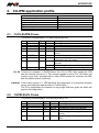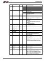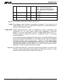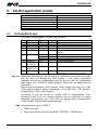
1
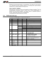
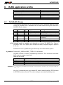
ACASYS-KS Communication in ACASYS system Programmer manual Version 1.07 acasys-ks_ms_en_107 ACASYS-KS AMiT, spol. s r.o. does not provide any warranty concerning the contents of this publication and reserves the right to change the documentation without obligation to inform anybody or authority about it. This document can be copied and redistributed under following conditions: 1. The whole text (all pages) must be copied without any changes. 2. All redistributed copies must retain the AMiT, spol. s r.o. copyright notice and any other notices contained in the documentation. 3. This document must not be distributed for purpose making of profit. The names of products and companies used herein can be trademarks or registered trademarks of their respective owners. AMiT is a registered trademark Copyright (c) 2014, AMiT, spol. s r. o. Producer: AMiT, spol. s r. o. Naskové 3/1100, 150 00 Praha www.amit.cz Technical support: [email protected] acasys-ks_ms_en_107 2/16 ACASYS-KS Contents History of revisions ......................................................................................... 4 Related documentation ................................................................................... 4 1. Introduction .......................................................................................... 5 2. Protocol specification ......................................................................... 6 2.1. 2.2. 2.3. 2.4. 2.5. IP addresses and ports ................................................................................... 6 Question/answer (Q/A) type communication .................................................. 6 “Parcel” type communication .......................................................................... 6 Communication type selection ........................................................................ 7 Frame structure .............................................................................................. 7 3. TRUD KS ............................................................................................... 9 3.1. IP monitor operation principle ......................................................................... 9 4. CU-IPM application profile ................................................................ 10 4.1. 4.2. TxCU-RxIPM Frame ..................................................................................... 10 TxIPM-RxCU Frame ..................................................................................... 10 5. CU-RU application profile ................................................................. 13 5.1. 5.2. TxCU-RxRU Frame ...................................................................................... 13 TxRU-RxCU Frame ...................................................................................... 14 6. IS-RU application profile ................................................................... 15 6.1. 6.2. TxIS-RxRU Frame ........................................................................................ 15 TxRU-RxIS Frame ........................................................................................ 16 3/16 acasys-ks_ms_en_107 ACASYS-KS History of revisions Document name: acasys-ks_ms_en_107.pdf Author: O. Stančík Revision 100 101 102 103 104 105 106 107 Date Changes 02. 08. 2012 New document 29. 10. 2012 Transmission ports are set to “Implementation independent” in accordance with actual implementation. Completion of information to the arrays with gps location for TxCU-RxRU 22. 11. 2012 Scenes configuration. Attachment of CAMS_MASK. 01. 12. 2012 Spelling check, document template update, editing of text in chapters 3.1 Example, 4.1 and 4.2 Backlight description, 5.1 GPS_xxx. 03. 07. 2013 Extension of TxRU-RxCU frame. 27. 09. 2013 Correction of TxIPM-RxCU frame length. 25. 11. 2013 Correction of TxCU-RxRU, TxIS-RxRU frame length. 11. 04. 2014 Detailed description of time synchronization (part TIME of TxCU-RxRU frame) was added. Paragraph in 4.2 about FSG_fields. Related documentation 1. ACASYS-KS Modular camera system – Projection manual file: acasys-ks_mp_en_xxx.pdf 2. User manual – Acasys Studio – Browser for videorecords from PPM2000 unit file: acasysstudio_ms_en_xxx.pdf acasys-ks_ms_en_107 4/16 ACASYS-KS 1. Introduction This document describes the communication interface between Camera system ACASYS-KS and surrounding units. The communication protocol is named TRUD. Camera system consist of IP monitors, IP cameras as and recording unit. IP monitors displays the video-stream from single or more cameras. The recording unit records image mostly from all cameras, with decreased fps (frames per second). IP monitors or recording unit can absent in camera system. 5/16 acasys-ks_ms_en_107 ACASYS-KS 2. Protocol specification Basic characteristic Client/server type protocol, based on Ethernet v2 (RFC 1191) link layer and UDP (RFC768) transport layer. Multibyte data types are coded in little-endian format. Every TRUD frame is transported just by single UDP packet. Therefore, into single UDP packet can not be placed more TRUD frames, and concurrently splitting a single TRUD frame into several UDP packets is not supported (Notice: it does not apply to fragmentation on IP layer level). Application In the application profile are determined the elementary communication profile parameters. The application profile is described hereafter. 2.1. IP addresses and ports Device IP addresses can be part of application profile or they can be defined in other document. Assigning of ports is included in application profile. 2.2. Question/answer (Q/A) type communication The question is sent to server in so called 'question-frame’ form. Based on content of corresponding inquiry the server sends the answer in so called ‘answer-frame’ form. Communication drop-out occurs when a timeout is detected while client is waiting for response. The timeout size is determined in application profile. Exchange The communication process is specified by sequence of exchanges of algorithm questions and responses in time period. The algorithm of single data exchange takes place in a different way for client and for server. From the client standpoint: 1. Question-frame assembly. 2. Sending of question-frame to the server. 3. During timeout waiting for server answer to the sent frame. 4. When the server's answer to the sent frame came before timeout elapsed, client can process the answer content. Otherwise an UDP dropout occurred and transmission is to be repeated. From the server standpoint: 1. Waiting for client’s question-frame. 2. Assembly of answer-frame depending on contents of question. 3. Sending the answer-frame to client. 2.3. “Parcel” type communication One station sends to the second a frame with relevant data, without acknowledgment request. The transmitting station supposes that other party will receive data. The communication can go also in the opposite direction, so both acasys-ks_ms_en_107 6/16 ACASYS-KS stations can mutually check their operation (but except for delivery of particular mail/“parcel“). This method of communication is intended for periodic data transfer. 2.4. Communication type selection To communicate with particular node must be determined certain communication type, which can not be changed at runtime. Q/A is designed for communication when changing values, the Parcel communication is designed for periodic data transfer. In both cases is used the same header, only its meaning is changed. 2.5. Frame structure Frame Each TRUD frame consists of header and payload, structure and content of structure which (it can be also completely omitted) depends on application. But the header structure is firmly determined. The header length is 8 bytes, the maximum permitted payload length is set to 1446 bytes. Together with headers of individual MAC, IP and UDP layers the total capacity 1500 bytes of Ethernet V2 frame is used. Item FLG LEN ID SEQ PLD Type U16 bit#0 bit#1 bit#2 to 15 U16 U16 U16 - Q/A Frame type 1 1 – Question 0 – Answer Meaningless Payload length in bytes Question type identifier Exchange identifier Payload (structure depends on type of question) P Frame type 0 Meaningless Meaningless Payload length in bytes Frame type identifier Meaningless Flags The FLG item represents an area for specification of 16 different flag types. The zero-bit with value equal to 1 states the Q/A type of communication and the reverse value the P communication. Bit 1 indicates question or answer and used primarily for service/ debugging purpose. When using the Q/A type communication the stations are obliged to fit this bit properly. Remaining bits are meaningless and their value is supposed to be zero. Identification The ID field specifies the type of question/ frame, i.e. meaning of frame or content of payload part PLD. SEQ meaning The role of SEQ item is to differentiate between the individual data exchanges. The client should set this item to a value, that he would be able to identify the relevant answer accordingly (in fact, the SEQ frame with relevant answer will include its copy). Using this mechanism the undesirable effects are eliminated, that could occur due to commutation of UDP packets order during data exchange, or by receiving of answers, client's timeout of which elapsed meanwhile. 7/16 acasys-ks_ms_en_107 ACASYS-KS Generating System of generating of SEQ values in questions is an issue of the client, the SEQ only task for server is to copy these values into relevant answers. For this purpose can be used for example a random number generator with even distribution or some form of packet content check sum combined with question sequence repetition. The algorithm, which is the simplest and recommended as well is the ordinary counter of exchanges. When using the Parcel-type communication, the SEQ field is ignored. Payload The structure of question frame payload PLD is determined by ID value. Then, the LEN item states the payload length in bytes. Its value must be within the interval from 0 to 1446. Data types In description of protocol are used names of data types with meaning as follows. Label U8/I8 U16/I16 U32/I32 F32 CSTR Type Integer without/with sign Integer without/with sign Integer without/with sign Float Character string with variable length terminated with binary zero Length (bits) 8 16 32 32 Data types are coded in little-endian format. The string-extension of basic data types used hereinafter is designated as type[n] expression, where ‚type‘ states the basic string type and ‚n‘ its length (the ‚n‘ is a natural number greater than 0). The character encoding type (ASCII, UTF-8, Unicode, …) is an integral part of application profile. acasys-ks_ms_en_107 8/16 ACASYS-KS 3. TRUD KS This document describes the communication between Central Unit and IP monitors, as well as communication between Central Unit and Recording Unit. Abbreviations used: CU Central Unit IPM IP monitor RU Recording Unit IS Information System 3.1. IP monitor operation principle IP monitor displays the video-stream from single or more IP cameras. Images from more cameras are displayed on monitor in tile-windows arrangement with maximum number 4 × 4 (multi-view). Viewing of particular camera or cameras must be firmly pre-defined. This is called ‘scene'. Then, through protocol, the CU sends an information to IPM, which scene is to be active at this moment. Scenes configuration as well as another monitor features are defined in text file, which is loaded at once with FTP or SSH protocol into monitor. To create or modify the configuration file you can use the ACASYS Configurator as service software. Example Let us have one IPM and two cameras on the left and right side. We want to display the left and right camera separately on the screen and then both cameras together. IP address of left camera is 192.168.1.1 and IP address of right camera is 192.168.1.2. Below is a segment of configuration file, that contains definition of streams with accordance to example stated above: stream=1;axis;192.168.1.1;0;Left;left camera stream=2;axis;192.168.1.2;0;Right;right camera stream=3;multi2x1;1,2;0;both the left and right camera in a single row To display the left camera on IPM the central unit sends the frame TxCU-RxIPM (see the 4.1 chapter) with value of SCENE parameter adjusted to 1. Then, value of SCENE parameter equal to 2 is used when displaying the right camera and value 3 when displaying both cameras. 9/16 acasys-ks_ms_en_107 ACASYS-KS 4. CU-IPM application profile Communication type Transmission period from CU Transmission period from IPM CU receive port CU transmission port IPM receive port IPM transmission port PARCEL Depends on implementation 1s 55000 Depends on implementation 55000 Depends on implementation 4.1. TxCU-RxIPM Frame This frame is transmitted by CU and received by IPM. Ofs 0 2 4 6 8 Item FLG LEN ID SEQ LIFETIME Type U16 U16 U16 U16 U8 Value 0x0000 6 0x0701 9 10 SCENE BACKLIGHT U8 U8 0 to 100 11 CAMDIAG U8 0 12 RX_TM U16 0 to 255 1 Meaning Frame type Payload length in bytes RxIPM-TxCU frame type identifier Ignored. Incrementing counter, indication of CU activity. Scene which is to be displayed on IPM. Adjustment of backlight intensity (percentual, with 10 % step). Do not perform diagnostics of connected cameras. Perform diagnostics of connected cameras. Timeout for receiving RxIPM frame [s] . RX_TM Timeout for reception of RxIPM frame from CU to IPM. After restart the IPM sets the internal counter to 0. This internal variable is set by RX_TM. When not equal to zero, then, provided that no other RPM frames are received, the IPM sets the default scene (if defined). CAMDIAG If this value equals to 1, IPM performs the diagnostics of connected cameras (ping), and diagnostic data are sent in TxIPM frame. The CU is responsible for selection of only single IPM from given set which will perform this diagnostics. 4.2. TxIPM-RxCU Frame This frame is transmitted by IPM and received by CU. Ofs 0 2 4 6 8 9 Item FLG LEN ID SEQ LIFETIME Type U16 U16 U16 U16 U8 SCENE U8 acasys-ks_ms_en_107 Value 0x0000 36 0x0700 0 to 255 10/16 Meaning Frame type Payload length in bytes TxIPM-RxCU frame type identifier Ignored. Incrementing counter, sign of IPM activity. Scene which is actually displayed on IPM. ACASYS-KS 10 BACKLIGHT U8 11 ERROR U8 0 to 100 13 14 RESERVED RX_TM U8 U16 16 CAMS U32 20 CAMS_MASK U32 24 U8 U8 Firmware version (minor). U16 Firmware revision 28 FIRMWARE_ MAJOR FIRMWARE_ MINOR FIRMWARE_ REVISION FSG_TOTAL Currently adjusted intensity of backlight (percentual value). Unit error code Without failure Unit’s internal temperature exceeded Unit internal error. Copy of CAMDIAG field from TxCURxIPM frame: Do not perform diagnostics of connected cameras Perform diagnostics of connected cameras. Reserved Current value of internal variable, that watches the timeout for reception of RxIPM frame. Resulting bit-array of ping to individual cameras: 0 – camera is not tested or does not respond 1 – camera detected. Tested camera bit-array: 0 – camera is not tested 1 – camera is tested Firmware version (major). U32 32 FSG_ERRORS U32 Total number of changes to the status code supervisory processor (see FSG_LATEST). Number of changes in status code supervisory CPU for error code – (see FSG_LATEST) FSG_ERRORS value increase during changing value in status code from 0x00 to any error code or transition from error code to another error code 36 38 FSG_LATENCY FSG_VERSION_ MAJOR FSG_VERSION_ MINOR FSG_LATEST U16 U8 0 1 2 12 CAMDIAG U8 0 1 25 26 39 40 Delay of frame [ms] Supervisory processor application version (major) Supervisory processor application version (minor) Status code (hex): 0x00 – normal operation, no error 0x41 – CRC error metadata of frame 0x42 – parity error metadata of frame 0x43 – toggle error metadata of frame 0x44 – identifier error metadata of U8 U8 11/16 acasys-ks_ms_en_107 ACASYS-KS 41 RESERVE1 U8 42 RESERVE2 U8 43 RESERVE3 U8 frame 0x45 – over limit of frame delay 0x46 – check off, performs self test 0x47 – internal error of supervisory processor Reserved for future use (should be ignored). Reserved for future use (should be ignored). Reserved for future use (should be ignored). RX_TM If the value is equal to zero, default scene is set. CAMS The bit-array, which indicates connecting of cameras. If the relevant bit of CAMS_MASK is set, then on related bit of CAMS item is present the result of testing of connecting the camera. CAMS_MASK Tested camera bit-array. Value is assembled by IPM in accordance with configuration file. For each defined stream that corresponds to particular camera (i.e. not the multi-stream), one bit of CAMS_MASK value is set to 1. Position of this bit in sequence is given by i-1 expression, where ‘i’ is a stream numerical identifier. In our example with three streams mentioned above, the CAMS_MASK field will have a value equal to 0x00000003, i.e. the lowest two bits, which corresponds to streams number 1 and 2 are set to log. 1. Stream 3 is multi-view, therefore the third bit (as well as all remaining bits) is set to log. 0. The CAMS_MASK value can be used by CU as fast detection of camera drop-out. If the equation (CAMS&CAMS_MASK)==CAMS_MASK is true, then all cameras are on-line. Otherwise, at least one camera drop-out occurred. FSG_xxx The fields with prefix FSG_ are used for supervisory processor if it is used in the IPM type. See the appropriate documentation for IPM type or project. In other cases the fields contain zeros and have to be ignored. acasys-ks_ms_en_107 12/16 ACASYS-KS 5. CU-RU application profile Communication type Transmission period from CU Transmission period from RU CU receive port CU transmission port RU receive port RU transmission port PARCEL Depends on implementation 1s 55001 Depends on implementation 55001 Depends on implementation 5.1. TxCU-RxRU Frame This frame is transmitted by CU and received by RU. Ofs 0 2 4 6 8 Item FLG LEN ID SEQ LIFETIME Type U16 U16 U16 U16 U8 9 CMD 10 14 VEHICLE GPS_ LATITUDE GPS_ LONGITUTE TIME U8 bit#0 bit#1 to 7 U32 I32 Meaning Frame type Payload length in bytes TxCU-RxRU frame type identifier Ignored. 0 to 255 Incrementing counter, sign of CU activity. Bit-coded report: 1 SOS – sos event activation. Reserved Vehicle identification -180 /180 Latitude in I32 format. I32 -180 /180 Longitude in I32 format. 18 22 Value 0x0000 18 0x0702 U32 Unix time format (number of seconds elapsed since 1970-01-01 midnight) GPS_xxx When both fields are zero, the GPS value is considered to be invalid. Recording Unit RU does not interpret the GPS location, it only saves information. Therefore, the format is meaningless from RU point of view. An interpretation takes place till in ACASYS Studio program, where the recorded data are processed. Initial format corresponds to I32 domain (32-bit integer with sign) on <-180, +180> degree range. It means, that range <-2 147 483 648, 2 147 483 647> corresponds to <-180, +180> degree. Conversion of one arc second to number 1000 is recommended. Then, calculations with 0.001 arc second precision can be performed in integer arithmetic. Subsequently, the <-180, +180> arc degree range corresponds to <-648 000 000, 648 000 000> numerical range. TIME RU accepts new value of TIME if TIME is not zero Last synchronization was at least SYNC_PROTECT_PERIOD ago 13/16 acasys-ks_ms_en_107 ACASYS-KS Rejecting of time synchronization is not signalised. The reason for such solution is to eliminate RU index problems when CU is sending time synchronization variation due to various reason including errors. SYNC_PROTECT_PERIOD After power up of the RU the first synchronization is always accepted. Then the synchronization protection period is valid and all time synchronization is rejected until this period elapsed. The default value of protection period is 8 hours. Other value can be set in a configuration (config.setSyncProtectionSeconds (4*3600)). 5.2. TxRU-RxCU Frame This frame is transmitted by RU and received by CU. Ofs 0 2 4 6 8 10 11 12 ERROR RESERVED CAMS bit#2 to 7 U8 U8 U32 16 CAMS_MASK U32 22 TIME U32 26 28 IS_COUNTER FIRMWARE_ MAJOR FIRMWARE_ MINOR FIRMWARE_ REVISION U32 U8 Meaning Frame type Payload length in bytes TxRU-RxCU frame type identifier Ignored. Incrementing counter, indication of IPM activity. Bit-coded report. SOS event activation. Recording is ON Recording is OFF due to CU request. Reserved Indication of RU internal error. Reserved for future use. Individual camera record bit-array. 0 – recording is OFF 1 – recording is ON Connected camera bit-array. 0 – camera is not connected 1 – camera is connected Actual unit time in Unix time format (number of seconds elapsed since 1970-01-01 midnight) Counter of reports from IS. Firmware version (major). U8 Firmware version (minor). U16 Firmware revision 9 29 30 Item FLG LEN ID SEQ LIFETIME Type U16 U16 U16 U16 U8 STATE U8 bit#0 bit#1 acasys-ks_ms_en_107 Value 0x0000 24 0x0703 0 to 255 1 0 1 14/16 ACASYS-KS 6. IS-RU application profile Communication type Transmission period from IS Transmission period from RU IS receive port IS transmission port RU receive port RU transmission port PARCEL Depends on implementation 1s Not used. Depends on implementation 55002 Not used. 6.1. TxIS-RxRU Frame This frame is transmitted by IS and received by RU. Received data are saved on disk in metadata form. Metadata can be used when working with records in ACASYS Studio viewer. Ofs 0 2 4 6 8 Item FLG LEN ID SEQ LIFETIME Type U16 U16 U16 U16 U8 9 10 MSG_TYPE U8 IS_MSG CSTR Value 0x0000 2 + sizeof(IS_MSG) 0x0704 0 to 255 Meaning Frame type Payload length in bytes TxCU-RxRU frame type identifier Ignored Incrementing counter, indication of CU activity. Determines the IS_MSG form. C-string LEN Payload length is variable and depends on size of IS_MSG. E.g.: Size of IS_MSG="Test!" is 6 Bytes (zero escape included). Payload length in bytes is 2 + 6 = 8. Particular form of IS_MSG string is defined by used information system. IS_MSG==0 Format of IS_MSG for MSG_TYPE==0 is as follows: IS_MSG consists of 6 items, separated by semicolon. The ‘semicolon’ character itself must not appear in any item. Here are the items LINEID DIR STNID STNAME GPGGA Line number. “0” backward ride, “1” forward ride. Current station numerical identifier. Current station name in UTF-8 code. GPS coordinates in GPGGA sentence format Example 9;0;;Kobylisy;$GPGGA,123519,4807.038,N,01131.000,E,1,08,0.9,545.4,M,46 .9,M,,*47 Line No. 9, backward ride, none station ID, station name Kobylisy, GPS location in GPGGA sentence format. The entire string is terminated by binary zero. 15/16 acasys-ks_ms_en_107 ACASYS-KS 6.2. TxRU-RxIS Frame RU does not transmit to IS. acasys-ks_ms_en_107 16/16