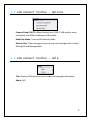
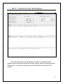
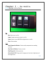
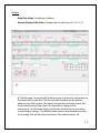
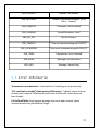
1
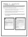
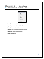
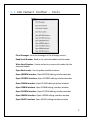
CAN Connect
User’s Manual
Rev 2
2-20-2012
CAN Connect User’s Manual
Index
Chapter 1 – Installation
pg 3
1.1 Windows XP/Windows 7
1.2 USB Connection
Chapter 2 – Interface
pg 5
2.1 CAN Connect Toolbar
2.2 Main Transmission Workspace
Chapter 3 - The Modules
3.1
3.2
3.3
3.4
3.5
482CRM Interface
521CRED Interface
524AM Interface
540SIM Interface
541CEI Interface
Chapter 4 – Tutorials
4.1
4.2
4.3
4.4
4.5
4.6
pg 13
pg 32
521CRED
524AM
482CRM
540SIM
541CEI
Post-Test Setup (Optional)
Chapter 5 – Error Messages
pg 43
5.1 Error Message Table
5.2 Error Information
2
Chapter 1 - Installation
1.1 Windows XP/Windows 7
Once HMI Systems has provided your CAN Connect install file, follow the steps
below to install the software onto your computer.
1. First locate your setup.exe file. Double-click the file to start installation. If
asked by windows to allow file to continue, click yes.
2. The CANcreate Software Suite window should show up. Read the License
Agreement and if you accept it, then click Install.
3. When completed, the message “Installation completed successfully” should
be in the message window. Locate the CANconnect icon on your desktop to
launch the software.
3
1.2 USB Connection
The CAN Connect software needs a CAN to USB adapter. It supports both
the 514UTC USB adapter and the PCAN Gridconnect USB/CAN adapter.
514UTC USB Adapter
PCAN Gridconnect USB/CAN Adapter
4
Chapter 2 - Interface
2.1 CAN Connect Toolbar - File
New- Open new .ccn file
Open- Open previously created .ccn file
Save- Save current .ccn file
Save As- Save current .ccn to specified location
Recent File- Open recently used files
Close- Close window
5
2.1 CAN Connect Toolbar - Tools
Clear Messages- Clear the messages in the Message section
Read Serial Number- Read in the selected module serial number
Write Serial Number- Create and write a new serial number for the
selected module
Open Boot Loader- Use to update module firmware
Open 482CRM Interface- Open 482CRM editing interface window
Open 521CRED Interface- Open 521CRED editing interface window
Open 524AM Interface- Open 524AM editing interface window
Open 529BIB Interface- Open 529BIB editing interface window
Open 531CRM Interface- Open 531CRM editing interface window
Open 540SIM Interface- Open 540SIM editing interface window
Open 541CEI Interface- Open 541CEI editing interface window
6
2.1 CAN Connect Toolbar - Advanced
View Module Details- Lists address, buffer size, and messages for
debugging
Device Listing- Scans for number of USB devices connected
Change Address- Change the address of the selected HMI module. This
refers to the HMI address stored internally that is used to differentiate
between multiple modules connected at once with different designs
programmed.
Note: This is not the physical source or destination address in the
CAN network. The address needs to be unique for each module.
7
2.1 CAN Connect Toolbar - Options
Connect Using 514UTC- When checked, uses 514UTC USB module; when
unchecked, uses PCAN GridConnect USB module
Read Only Mode- Turns on/off read only mode
Receive Filter- Filters message section to view only messages with a certain
Message ID and Message Mask
2.1 CAN Connect Toolbar - Help
Title- Displays CANconnect version number and copyright information
About- N/A
8
2.2 Main Transmission Workspace
This is the main CAN Connect window. Through it, all USB connected
modules can be monitored and edited through various separate interfaces within
CAN connect. The various components of this workspace are detailed in this
chapter.
9
2.2 Main Transmission Workspace (Cont)
Request Broadcast- After hooking up your CAN system to the PC, request
broadcast will locate the attached modules. The modules will show up in the
Modules section and corresponding messages in the Message section.
Interrogate Module- Returns the module address and version information that is
selected
Open Interface- Opens the editing interface for the selected module
Request Serial #'s- Reads and lists the serial number for the selected module in
the information message section
Under the Design Control section:
New Module- Create new Module with specific address and module type
Change Address- Change the Address of the selected Module
Delete Module- Deletes the selected Module
10
2.2 Main Transmission Workspace (Cont)
Under the Hardware Address Control section:
-Use select to pick module
-Can read or write displayed address of selected module
- Use master to communicate with any module regardless of address
Note: Should only be used when one module is attached to CAN
network at a time. The master address can be selected and force a
module of unknown address to the displayed address by clicking the
write button
Modules Section:
-Lists the connected modules
-Displays the following information:
-Address, Serial Number, Module Type, Version Number, CAN ID,
Buffer Number
11
2.2 Main Transmission Workspace (Cont)
Messages Section:
-Lists the incoming messages from the connected modules
-Displays the following information:
-CAN ID, Bytes, Data, Period, Count, Changes
Information Message Section:
-The information message section indicates what actions have occurred and
may be currently executing. Any errors or successful module commands will be
shown in this message section.
12
Chapter 3 – The Modules
3.1 482CRM Interface
File
New- Open new .crm file
Import- Import previously created .crm file
Export- Export current 482CRM configuration as .crm file
Close- Close window
Tools
Open Diagnostics Window- Tests to verify components are working
correctly
Open Burn In Window- Factory use only
Read Diagnostics- Factory use only
Rotate Switch 180- Change switch assignments from low to high byte and
from high to low
13
Options
Read Only Mode- No editing is allowed
Reverse Displayed Bit Order- Changes the bit order from 0-> 7 to 7->0
A. The Message Transmitted By Module section is where the information to
be transmitted is specified. The first text field includes the destination
address in the CAN system. The Bytes field specifies how many bytes. The
Period field specifies how often the information is being sent in
milliseconds. The Minimum field is the fastest the data can be sent when
transmitting on change. The NAME button opens a new window that edits
the message that will be transmitted when the module powers up.
14
B. This is the visual representation of the bytes being transmitted. Each
byte is broken down into each of its 8 bits. Here the individual bits, within
each byte, can be changed to be associated with a certain switch and/or
switch position that the receiving CAN module can decode.
C. The Message Received By Module section is where the address and mask
can be set to listen to the correct module. The number of bytes to use is
specified and if you want to the cycle the test when testing the LED
configuration using the LED On and LED Off buttons.
D. This is a visual representation of the bytes received and what the
significance of each bit has for the LEDs on the module. Using the tools
below, LEDs can be set to a variety of colors and locations (top or bottom
LED on switch).
E. The Bit Selector includes False, True, Switch, LED, Enable, Power, Enable
All, Power All, Red LED, Green LED, and Blue LED. Each affects the switches
in a certain way. Some are associated with a certain color, which will be
seen in the square next to the drop down menu. Enable, for example, is
represented with yellow. The number field can be set from 1 to 8. Each
represents a switch on the module (from left to right starting with 1). Set
the value as 2, insert a Red LED, and the number will be shown as 2
meaning switch 2. The drop down menu with top and bottom is used to
select the top or bottom LED on the switch. Checking the Invert box will set
the LED to be true on zero instead of a one.
Bit Types:
False – This bit will always transmit as a zero. Has no effect on
received messages.
True – This bit will always transmit as a one. Has no effect on
received messages.
Switch – Represents the status of a switch. Use the switch selector to
select which of the eight switches, and the row selector to select
whether it’s the up or down switch. Has no effect on received
messages.
LED – Used to control the LED. Use the switch selector to select
which of the eight switches, and the row selector to select whether
15
it’s the top or bottom LED. Transmitted messages with LED bits will
reflect the status of the last received message.
Enable – A single bit that enables the top or bottom row of LEDs. This
control is optional. If no enable bit is specified, the LEDs will default
to on. Use Enable All to enable both the top and bottom rows of LEDs
with a single bit.
Power – Up to eight bits for each row that represent the power
(intensity) of the LEDs. A value of 0 is 0% and a value of 255 is 100%.
Any power bits after the first eight will be ignored. If less than eight
bits are specified, the least significant bits are filled in with the
value of the most significant bit. (The bits specified are assumed to
be the most significant) This control is optional. If no power bits are
specified, the LEDs will default to 100% on. Use Power All to set the
power of both the top and bottom rows of LEDs with the same value.
F. The Colors drop down menu has a selection of colors from black to white.
The top 8 boxes represent the top LEDs on 8 switches. The bottom 8 boxes
represent the bottom LEDs on 8 switches. Using the drop-down menu,
colors can be put into the boxes. Then use the Bit Selector “LED” option in
the Message Received bytes to enable that color in the corresponding bit.
This method allows for LED control condensed to 2 bytes, but limits the LED
customization.
G. Under Design Controls, the design can be programmed onto the module
through Write Design. You can verify the design on the current module
through Verify Design. To import the current design from the module, use
Read Design. To get the module's address and version information, use
Interrogate Module. You can use Disable Config to disable configuration on
the module. There is also a Set to Demo Mode button to put the module
into demo mode.
Note: Bad response message may occur upon request, check
connections and retry Read Design.
H. The information message section indicates what actions have occurred
and may be currently executing. Any errors or successful read/write/verify
messages will be shown in this message section.
16
482CRM Physical Device
The switches can be set up for many different uses. The switch can rock up
and down, to be used for an increasing/decreasing function. Single directional
rocker switch can also be used. If not all switches are used, a blank dummy switch
can be inserted.
17
3.2 521CRED Interface
File
Close- Closes the window
Connect
Interrogate Module- Returns the device address and version information
that is being edited
Write Design- This exports the newly created design to the device to use
Verify Design- This checks to make sure the design is correct on the device
Read Design- This imports the design that is currently stored on the device
Note: Bad response message may occur upon request, check
connections and retry Read Design.
Read Diagnostics- Factory use only
18
A. When connected to the module, each Channel will display the
corresponding number on the module. The empty bar next to each channel
will visually fill up when reaching its programmed maximum. The actual
number will be displayed next to it.
B. The Channel Configuration section has Channel 1 displayed first by
default. This section allows the setting of the minimum, maximum, and
decimal location for each channel. Use the drop down menu next to
“Channel:” to select channels 1 to 4. The minimum allowed is 0 and the
maximum allowed is 9999. Checking the enable box, turns on and off a
channel. Checking the Rollover box will allow the user to return to the
minimum when the maximum is reached without turning the dial back the
same direction.
19
C. Within the Message Configuration section, the Message drop down
menu can select between 4 different messages. Each message will have its
own Message ID and specify its own selection of bytes to receive/read. Use
the Enabled check box to turn on and off individual messages. Check the
Transmit on Change box to transmit a message every time the value
changes, unless it will only transmit at the set transmission period. Set the
transmission period in milliseconds in the Transmission Period field and set
the minimum period in the Minimum Period field. Use Bytes 1 to 8 and the
drop down menu adjacent to specify the channel it associates with and
whether it uses the high or low byte.
D. The Buttons make sure the buttons are working correctly. The Test
Counters are for factory use only.
E. The information message section indicates what actions have occurred
and may be currently executing. Any errors or successful read/write/verify
messages will be shown in this message section.
20
521CRED Physical Device
The module has a digital display, 3 buttons, and the adjustment dial. The 2
buttons with the up and down arrows increase/decrease the channel being
accessed. The lock button can be set to lock the channel and dial (defaults as free
input). Turn the dial clockwise to increase the numbers and counter-clockwise to
decrease them. Tuning the dial faster will change the numbers at a quicker rate,
while turning it slower will provide a more accurate, fine tuning adjustment.
Note: Turning the dial too quickly may cause it to skip increments.
21
3.3 524AM Interface
File
Close- Closes the window
Connect
Interrogate Module- Returns the device address and version information
that is being edited
Write Design- This exports the newly created design to the device to use
Verify Design- This checks to make sure the design is correct on the device
Read Design- This imports the design that is currently stored on the device
Note: Bad response message may occur upon request, check
connections and retry Read Design.
Read Diagnostics- Factory use only
22
A. The Configure Alarm box allows for the implementation of 4 individual
alarms or actions on the same device that correspond to different
messages on the CAN bus. Use the drop down box to select between them.
Note: The same message mask will be shared across all 4 alarms.
B. The Message ID is a 29 bit CAN ID that is associated with each alarm. Use
the Message Mask to mask out what bytes are needed and not needed for
the alarm to sound. If the Data Bytes match the Data Mask, the alarm will
be triggered. The Data Bytes and Data Mask are bitwise ANDed together so
a single bit in the message can be isolated to trigger the alarm. Use the
transmit button to send the current Message ID and Data Bytes over the
CAN interface to test the alarm. The drop down menu (default set to alarm)
can change what action the message triggers. Actions include disabled,
alarm, clear, and silence.
-Disabled means the message isn’t used.
23
-Alarm means the alarm pattern is played if criteria is matched
-Clear means the message clears all active alarms, silences them, and
clears all LED if criteria is matched
-Silence means the message silences all active alarms if criteria is
matched, clears warning LED, but Error LED will remain active
C. Checking the “Enable Manual Controls” box enables these testing
options. With a device connected, the volume control can be increased and
decreased in the box next to the Volume Control to test out what the
appropriate volume level is for the current implementation. The two LED
check boxes and Switch boxes allow for testing of those functions as well.
Note: Enable Manual Controls are software features only and don’t
affect the actual testing of the module.
D. The Pattern section specifies the 64 bit configurable tone pattern to be
played when the correct message is received by the module. The periods
“.” in the pattern turn the buzzer off and the lines “|” in the pattern turn
the buzzer on. Continuous tones can be produced by multiple adjacent
periods or lines. To create your own pattern, input zeros into the Pattern
section to specify periods and ones to specify lines. Once 64 characters are
typed in, the program will switch them to periods and lines for better
readability.
E. Below the pattern section is the Count, Speed, and Volume fields. The
Count field defines how many times the pattern will be played upon
receiving the correct message and data combination. Setting the count to
255 will repeat the alarm indefinitely and require either a message to clear
or direct input from the operator through the mute button on the unit. The
Speed field will determine how fast the pattern is played upon receiving the
correct message and data combination. The lower the number, the faster
the message will be played; higher numbers (up to 255) add delay in
between each of the Pattern's bits. The Volume field will determine how
loud each Pattern will be played. The volume goes from 1 to 255 (max). Full
volume is approximately 105dB.
24
F. Checking the Enable Status Message box will allow the ability to echo
back a status message. The status message will indicate the current state of
the LED and switch. Set the Message ID and the period then it will start
broadcasting the information.
Status messaged defined:
Byte 1 –
Bit 0 – Warning LED
Bit 1 – Error LED
Bit 2 – Switch status (1 = pressed, 0 = not pressed)
Byte 2 –
Current active alarm (value from 1 to 4)
G. The information message section indicates what actions have occurred
and may be currently executing. Any errors or successful read/write/verify
messages will be shown in this message section.
524AM Physical Device
Two indicators are provided for warnings and errors. The default mode will
illuminate the red error LED and green warning LED during an alarm annunciation.
Hitting the mute button will turn off the alarm annunciation tone. The green
warning LED will remain lit until after the alarm annunciation is finished, even if
the mute button is pressed. The red error LED will remain lit until the mute button
is pressed.
25
3.4 540SIM Interface
File
New- Resets all values in the interface to defaults
Close- Closes the window
Tools
Open Diagnostics Window- Factory use only
Connect
Interrogate Module- Returns the device address and version information
that is being edited
Write Design- This exports the newly created design to the device to use
Verify Design- This checks to make sure the design is correct on the device
26
Read Design- This imports the design that is currently stored on the device
Note: Bad response message may occur upon request, check
connections and retry Read Design.
Read Diagnostics- Factory use only
A. When connected to the module, each Channel will display the
corresponding voltage value on the module. The empty bar next to each channel
will visually fill up in accordance to the value being read. The actual number will
be displayed next to it.
B. Under the Channel Configuration, there are 3 fields. The Channel field
contains a drop-down menu to select what channel that you want to edit
(Channels 1 to 5). The Zero Offset and Multiplier field are used to calibrate the
module for the system. For channels 3 to 5, the Voltage Mode box can be checked
and activated.
Note: When voltage mode is unchecked, these channels will measure a
resistive input
27
C. Under Message Configuration, the Message field drop-down menu can
be used to add/edit up to 5 different messages. Checking the Enabled box will
activate that message number. They each have their own Message ID which can
be changed in the Message ID field. Checking the Transmit On Change will have
the module send data every time it gets modified instead of waiting for the set
transmission period. It will not transmit any faster than the value set in the
Minimum Period field.
D. There are 8 Byte fields, each can be set to look at a certain channel's
voltage and select either the low byte, high byte, adjusted byte, or make it a
status register. The resolution of the value is actually 10 bits so a maximum value
of 1024, in order to get the full representation it takes 16 bits to transfer the data
but the real value is only 10 bits. Use the adjusted byte to get a converted input
value in 8 bit form instead of 16 bit. The status register is used for error detection
resulting from external fault due to a fuse trip.
E. The information message section indicates what actions have occurred
and may be currently executing. Any errors or successful read/write/verify
messages will be shown in this message section.
28
3.5 541CEI Interface
File
New- Resets all values in the interface to defaults
Close- Closes the window
Tools
Open Diagnostics Window- Factory use only
Connect
Interrogate Module- Returns the device address and version information
that is being edited
Write Design- This exports the newly created design to the device to use
Verify Design- This checks to make sure the design is correct on the device
29
Read Design- This imports the design that is currently stored on the device
Note: Bad response message may occur upon request, check
connections and retry Read Design.
Read Diagnostics- Factory use only
A. The Message ID field edits the specific address for the module. When the
Transmit on Change box is checked, the module will send the new data before the
Transmission Period. It will not transmit any faster than the Minimum Period. The
Bytes drop-down menu changes the number of bytes to be looked at.
B. This lists the inputs coming into the module. Next, in the Byte column,
each input has a drop-down menu to select what byte it will be compared to
(Bytes 1 to 8). In the Bit column, each input has a drop-down menu to select
which bit from the previously selected byte to use. Finally, the Active Low check
box can be used to change from active high to active low or active low to active
high. The Toggle All button can be used to check or uncheck all the boxes at once.
30
C. Under the Constant section, each Byte being used can be set using a
constant. By default, all are set to 00. The constant value is exclusive ORed with
the value detected on the input. When an active high input is selected the nonactive result is true. When the input is detected as being active high, the result
will be false.
Example: Bit 0 of byte 1 is active high. When the external input is pulled
low bit 0 is 1. When the external input is pulled high bit 0 is 0. Writing a
value of 01 to the constant field will XOR the results so that the external
input pulled low equates bit 0 to 0 and the external input pulled high
equates bit 0 to 1.
D. The information message section indicates what actions have occurred
and may be currently executing. Any errors or successful read/write/verify
messages will be shown in this message section.
31
Chapter 4 – Tutorials
4.1 521CRED Tutorial
Note: This requires a CAN-USB adapter and 521CRED module.
1. Connect the 521CRED module to the PC via a CAN to USB adapter.
2. Open CANconnect and click Request Broadcast. The attached module
should show up in the Modules section. Double-click the module to open
up the editing interface.
32
3. Go to Connect and interrogate Module. In the information message field,
the address of the module, the model, and firmware version are listed.
4. Under the Channel Configuration section, use the drop-down menu to
select between each channel. Use the check box to enable each channel
and set each with a minimum to 0 and maximum to 9999. Rollover should
also be active.
5. Under the Message Configuration, let only Message 1 be enabled. Set the
transmission period to 1000ms and minimum period to 100ms.
6. Write the Message ID to “18FEF44A” with Transmit on Change checked.
Note: This Message ID is for illustrative purposes only and can be set
to whatever works with your system.
7. Using the drop-down menus, set Byte 1 to “Channel #1 Low Byte” and Byte
2 to “Channel #2 High Byte”. For bytes 3 to 8, set to Constant.
8. Go to Connect and Write Design. The module is now programmed.
9. OPTIONAL: Follow the Post-Test Setup instructions to test the newly edited
521CRED.
33
4.2 524AM Tutorial
Note: This requires a CAN-USB adapter and an 8 switch 524AM module.
1. Connect the 524AM module to the PC via CAN to USB adapter.
2. Open CANconnect and click Request Broadcast. The attached module
should show up in the Modules section. Double-click the module to open
up the editing interface.
3. Go to Connect and interrogate Module. In the information message field,
the address of the module, the model, and firmware version are listed.
4. The Volume Control field is used to test the correct volume for the module.
Setting a number in the field and clicking the “On” button will play that
sound from the module. Leave Disable Manual Controls checked.
34
5. Under Configure Alarm, select Alarm #1. For Message ID, write in
“18FEF44B”. Next, in the Data Bytes field and Data Mask field put “01 00 00
00 00 00 00 00”. In the Message Mask field, put “1FFFFFFF”.
Note: This Message ID is for illustrative purposes only and can be set
to whatever works with your system.
6. To specify the pattern, use 1's and 0's. Type in
“111100001111000011110000111100001111000011110000111100001111
0000”. This will then change to
“||||....||||....||||....||||....||||....||||....||||....||||....” for a better
visualization of the pattern.
7. Finally, set Count to 3 (to repeat the pattern 3 times), set Speed to 1, and
Volume to 50.
8. Go to Connect and Write Design. The module is now programmed.
9. OPTIONAL: Follow the Post-Test Setup instructions to test the newly edited
524AM.
35
4.3 482CRM Tutorial
Note: This requires a CAN-USB adapter and 482CRM module.
1. Connect the 482CRM module to the PC via CAN to USB adapter.
2. Open CANconnect and click Request Broadcast. The attached module
should show up in the Modules section. Double-click the module to open
up the editing interface.
3. Go to Connect and interrogate Module. In the information message field,
the address of the module, the model, and firmware version are listed.
4. Under Message Transmitted By Module, set the ID field as “18EFFF94”. Set
Bytes at 8, Period to 1000ms, and Minimum to 100ms.
Note: This Message ID is for illustrative purposes only and can be set
to whatever works with your system.
36
5. For the Byte/Bit representation field, use the Bit Selector drop down menu
to select Switch with the value 1 and Top in the corresponding fields. Click
in bit 0 of Byte 1. A light blue box should show up with “1” inside and an
white oval at the top. Change the value under Bit Selector to 2. Click bit 1 of
Byte 1. Repeat until all 8 bits are filled in Byte 1. The last should be switch 8
in bit 7.
6. For Byte 2, repeat step 5 except change the Top property to Bottom. Leave
Bytes 3 to 8 blank.
7. Under Message Received By Module, set the ID field as “18EFFF93” and
Mask as “1FFFFFFF”. Leave Bytes as 8 and Cycle Test unchecked.
Note: This Message ID is for illustrative purposes only and can be set
to whatever works with your system.
8. Use the Bit Selector to pick Red LED, set the value as 1 and drop-down
menu to Top. Click the bit 0 in Byte 1 of the receiving message. Increment
the value to 2 and click bit 1 in Byte 1.Repeat up to value 8 for bit 7.
9. Change the property to bottom and repeat step 8 for Byte 2.
10.Change the Bit Selector to Green LED and repeat step 8 for Byte 3. Then
change the property to bottom and fill in Byte 4.
11.Change the Bit Select to Blue LED and repeat step 8 for Byte 5. Then change
property to bottom and fill in Byte 6.
12.Next, use the Bit Selector to pick Enable All. Click bit 0 in Byte 7. A yellow
box with two white ovals should be placed.
13.Return to the Bit Selector and change to Power. Make sure the top
property is active. Click on bits 0 to 3 in Byte 8. Purple boxes should be
placed with top ovals. For bits 4 to 7, use Power with bottom property
active.
14.Go to Connect and Write Design. The module is now programmed.
15.OPTIONAL: Follow the Post-Test Setup instructions to test the newly edited
482CRM.
37
4.4 540SIM Tutorial
Note: This requires a CAN-USB adapter and 540SIM module.
1. Connect the 540SIM module to the PC via CAN to USB adapter.
2. Open CANconnect and click Request Broadcast. The attached module
should show up in the Modules section. Double-click the module to open
up the editing interface.
3. Go to Connect and interrogate Module. In the information message field,
the address of the module, the model, and firmware version are listed.
38
4. Under Channel Configuration, verify that Channel #1 has a zero Offset of 0
and Multiplier of 1.
5. Next, under Message Configuration, check the box to enable message #1.
Set the Transmission Period to 1000ms. For the Message ID, write in
“18EFFF96”. Leave Transmit On Change unchecked.
Note: This Message ID is for illustrative purposes only and can be set
to whatever works with your system.
6. For Byte #1, use the drop-down menu to select “Channel #1 Low Byte”.
Next, set Byte #2 to “Channel #1 High Byte”. In Byte #3, set it to “Channel
#1 Adjusted”. Finally, in Byte #4, select “Status Register”. For the remaining
bytes, set them all as “Constant” with “00” in each number field next to
them.
7. Go to Connect and Write Design. The module is now programmed.
8. OPTIONAL: Follow the Post-Test Setup instructions to test the newly edited
540SIM.
39
4.5 541CEI Tutorial
Note: This requires a CAN-USB adapter and 541CEI module.
1. Connect the 541CEI module to the PC via CAN to USB adapter.
2. Open CANconnect and click Request Broadcast. The attached module
should show up in the Modules section. Double-click the module to open
up the editing interface.
3. Go to Connect and interrogate Module. In the information message field,
the address of the module, the model, and firmware version are listed.
40
4. In the Message ID field, write “18EFFF97”. Check the Transmit On Change
box. Set the Transmission Period to 1000ms and Minimum Period to
100ms. Make sure Bytes is set to 8.
Note: This Message ID is for illustrative purposes only and can be set
to whatever works with your system.
5. For every input (#1 to #8), under the Byte column, set each drop-down
menu to #1.Under the Bit column, set Input #1 to 0. For Input #2, set bit to
1. Repeat for Inputs #3 to #8 with bits 2 to 7.
6. Click Toggle All to make all Active Low boxes checked.
7. Under the Constant list of Bytes on the right, set Byte #1 to 55. Leave Bytes
#2 to #8 as 00.
8. Go to Connect and Write Design. The module is now programmed.
9. OPTIONAL: Follow the Post-Test Setup instructions to test the newly edited
541CEI.
41
4.6 Post-Test Setup (OPTIONAL)
Once done with a tutorial:
1. Open up CANcreate and load the “TestLab.ccs” file.
Note: If none of the images loaded, open the Image Library,
and click Import Image Pack. Locate the “testlab.cip” file and
click open. Click Refresh in the Image Library and then Reload.
2. Enable CAN Simulation and the CANcreate simulator.
Note: Make sure CAN Connect isn't open when testing with
the CANcreate software.
3. Use the virtual display to select the appropriate module and open up
the module’s page.
4. From the simulator, you can observe the receiving and transmitting
of data between the software and the CAN module.
42
Chapter 5 – Error Messages
5.1 Error Message Table
Error
Message
ERR_OK
"OK"
ERR_XMTFULL
"Send Buffer Full"
ERR_OVERRUN
"Overrun"
ERR_BUSLIGHT
"Bus Light"
ERR_BUSHEAVY
"Bus Heavy"
ERR_BUSOFF
"Bus Off"
ERR_QRCVEMPTY
"Receive Queue Empty"
ERR_QOVERRUN
"Receive Queue Overrun"
ERR_QXMTFULL
"Send Queue Full"
ERR_REGTEST
"Register Test Failed"
ERR_NOVXD
"No VxD Available"
ERR_HWINUSE
"Hardware in Use"
ERR_NETINUSE
”Net in Use"
ERR_ILLHW
"Invalid Hardware Handle (Device Not
Connected)"
ERR_ILLNET
"Invalid Net Handle"
43
ERR_ILLCLIENT
"Invalid Client Handle"
ERR_RESOURCE
"Unable to Generate Resource (FIFO,
Client, Timeout)"
ERR_PARMTYP
"Parameter Not Permitted"
ERR_PARMVAL
"Invalid Parameter Value"
ERR_NO_DLL
"No DLL Present"
ERR_TIMEOUT
"Time out communicating with 514UTC"
ERR_DATAERROR
"Data error communicating with 514UTC"
ERR_TXERR
"Transmission Error Detected"
ERR_MLOA
"Message Lost Arbitration"
ERR_ABTF
"Message Aborted Flag"
5.2 Error Information
Transmission error detected – A connection isn’t working or set up correctly
“DLL could not be loaded” when opening CANconnect - Typically means that you
already have a copy of CANconnect open or the GridConnect drivers have not
been loaded.
Fail to Read/Write- Bad response message may occur upon request, check
connections and retry Read/Write Design.
44