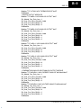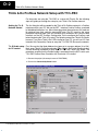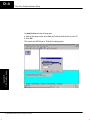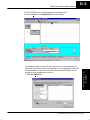
1
T1H–PBC Profibus DP Base Controller User Manual Manual Number T1H–PBC–M WARNING Thank you for purchasing automation equipment from Automationdirect.com. We want your new DirectLOGIC automation equipment to operate safely. Anyone who installs or uses this equipment should read this publication (and any other relevant publications) before installing or operating the equipment. To minimize the risk of potential safety problems, you should follow all applicable local and national codes that regulate the installation and operation of your equipment. These codes vary from area to area and usually change with time. It is your responsibility to determine which codes should be followed, and to verify that the equipment, installation, and operation are in compliance with the latest revision of these codes. At a minimum, you should follow all applicable sections of the National Fire Code, National Electrical Code, and the codes of the National Electrical Manufacturer’s Association (NEMA). There may be local regulatory or government offices that can also help determine which codes and standards are necessary for safe installation and operation. Equipment damage or serious injury to personnel can result from the failure to follow all applicable codes and standards. We do not guarantee the products described in this publication are suitable for your particular application, nor do we assume any responsibility for your product design, installation, or operation. Our products are not fault–tolerant and are not designed, manufactured or intended for use or resale as on–line control equipment in hazardous environments requiring fail–safe performance, such as in the operation of nuclear facilities, aircraft navigation or communication systems, air traffic control, direct life support machines, or weapons systems, in which the failure of the product could lead directly to death, personal injury, or severe physical or environmental damage (”High Risk Activities”). Automationdirect.com specifically disclaims any expressed or implied warranty of fitness for High Risk Activities. For additional warranty and safety information, see the Terms and Conditions section of our Desk Reference. If you have any questions concerning the installation or operation of this equipment, or if you need additional information, please call us at 770–844–4200. This publication is based on information that was available at the time it was printed. At Automationdirect.com we constantly strive to improve our products and services, so we reserve the right to make changes to the products and/or publications at any time without notice and without any obligation. This publication may also discuss features that may not be available in certain revisions of the product. Trademarks This publication may contain references to products produced and/or offered by other companies. The product and company names may be trademarked and are the sole property of their respective owners. Automationdirect.com disclaims any proprietary interest in the marks and names of others. Copyright 2001, Automationdirect.com Incorporated All Rights Reserved No part of this manual shall be copied, reproduced, or transmitted in any way without the prior, written consent of Automationdirect.com Incorporated. Automationdirect.com retains the exclusive rights to all information included in this document. AVERTISSEMENT Nous vous remercions d’avoir acheté l’équipement d’automatisation de Automationdirect.comE. Nous tenons à ce que votre nouvel équipement d’automatisation DirectLOGIC fonctionne en toute sécurité. Toute personne qui installe ou utilise cet équipement doit lire la présente publication (et toutes les autres publications pertinentes) avant de l’installer ou de l’utiliser. Afin de réduire au minimum le risque d’éventuels problèmes de sécurité, vous devez respecter tous les codes locaux et nationaux applicables régissant l’installation et le fonctionnement de votre équipement. Ces codes diffèrent d’une région à l’autre et, habituellement, évoluent au fil du temps. Il vous incombe de déterminer les codes à respecter et de vous assurer que l’équipement, l’installation et le fonctionnement sont conformes aux exigences de la version la plus récente de ces codes. Vous devez, à tout le moins, respecter toutes les sections applicables du Code national de prévention des incendies, du Code national de l’électricité et des codes de la National Electrical Manufacturer’s Association (NEMA). Des organismes de réglementation ou des services gouvernementaux locaux peuvent également vous aider à déterminer les codes ainsi que les normes à respecter pour assurer une installation et un fonctionnement sûrs. L’omission de respecter la totalité des codes et des normes applicables peut entraîner des dommages à l’équipement ou causer de graves blessures au personnel. Nous ne garantissons pas que les produits décrits dans cette publication conviennent à votre application particulière et nous n’assumons aucune responsabilité à l’égard de la conception, de l’installation ou du fonctionnement de votre produit. Nos produits ne sont pas insensibles aux défaillances et ne sont ni conçus ni fabriqués pour l’utilisation ou la revente en tant qu’équipement de commande en ligne dans des environnements dangereux nécessitant une sécurité absolue, par exemple, l’exploitation d’installations nucléaires, les systèmes de navigation aérienne ou de communication, le contrôle de la circulation aérienne, les équipements de survie ou les systèmes d’armes, pour lesquels la défaillance du produit peut provoquer la mort, des blessures corporelles ou de graves dommages matériels ou environnementaux (”activités à risque élevé”). La société Automationdirect.comE nie toute garantie expresse ou implicite d’aptitude à l’emploi en ce qui a trait aux activités à risque élevé. Pour des renseignements additionnels touchant la garantie et la sécurité, veuillez consulter la section Modalités et conditions de notre documentation. Si vous avez des questions au sujet de l’installation ou du fonctionnement de cet équipement, ou encore si vous avez besoin de renseignements supplémentaires, n’hésitez pas à nous téléphoner au 770–844–4200. Cette publication s’appuie sur l’information qui était disponible au moment de l’impression. À la société Automationdirect.comE, nous nous efforçons constamment d’améliorer nos produits et services. C’est pourquoi nous nous réservons le droit d’apporter des modifications aux produits ou aux publications en tout temps, sans préavis ni quelque obligation que ce soit. La présente publication peut aussi porter sur des caractéristiques susceptibles de ne pas être offertes dans certaines versions révisées du produit. Marques de commerce La présente publication peut contenir des références à des produits fabriqués ou offerts par d’autres entreprises. Les désignations des produits et des entreprises peuvent être des marques de commerce et appartiennent exclusivement à leurs propriétaires respectifs. Automationdirect.comE nie tout intérêt dans les autres marques et désignations. Copyright 2001, Automationdirect.comE Incorporated Tous droits réservés Nulle partie de ce manuel ne doit être copiée, reproduite ou transmise de quelque façon que ce soit sans le consentement préalable écrit de la société Automationdirect.comE Incorporated. Automationdirect.comE conserve les droits exclusifs à l’égard de tous les renseignements contenus dans le présent document. 1 Manual Revisions If you contact us in reference to this manual, be sure to include the revision number. Title: Terminator I/O Profibus DP Base Controller User Manual Manual Number: T1H–PBC–M Edition Original Date 5/02 Description of Changes Original issue 1 Table of Contents i Chapter 1: Introduction Manual Overview . . . . . . . . . . . . . . . . . . . . . . . . . . . . . . . . . . . . . . . . . . . . . . . . . . . . . . . . . . . . . . . . . . . . Overview of this Manual . . . . . . . . . . . . . . . . . . . . . . . . . . . . . . . . . . . . . . . . . . . . . . . . . . . . . . . . . . . Supplemental Manuals . . . . . . . . . . . . . . . . . . . . . . . . . . . . . . . . . . . . . . . . . . . . . . . . . . . . . . . . . . . . Who Should Read this Manual . . . . . . . . . . . . . . . . . . . . . . . . . . . . . . . . . . . . . . . . . . . . . . . . . . . . . Technical Support . . . . . . . . . . . . . . . . . . . . . . . . . . . . . . . . . . . . . . . . . . . . . . . . . . . . . . . . . . . . . . . . . Symbols Used . . . . . . . . . . . . . . . . . . . . . . . . . . . . . . . . . . . . . . . . . . . . . . . . . . . . . . . . . . . . . . . . . . . . Key Topics for Each Chapter . . . . . . . . . . . . . . . . . . . . . . . . . . . . . . . . . . . . . . . . . . . . . . . . . . . . . . . Introduction to Profibus . . . . . . . . . . . . . . . . . . . . . . . . . . . . . . . . . . . . . . . . . . . . . . . . . . . . . . . . . . . . . PROFIBUS Concepts . . . . . . . . . . . . . . . . . . . . . . . . . . . . . . . . . . . . . . . . . . . . . . . . . . . . . . . . . . . . . PROFIBUS International . . . . . . . . . . . . . . . . . . . . . . . . . . . . . . . . . . . . . . . . . . . . . . . . . . . . . . . . . . . PROFIBUS Trade Organization . . . . . . . . . . . . . . . . . . . . . . . . . . . . . . . . . . . . . . . . . . . . . . . . . . . . . DP Communication Profile . . . . . . . . . . . . . . . . . . . . . . . . . . . . . . . . . . . . . . . . . . . . . . . . . . . . . . . . . . . Terminator I/O System . . . . . . . . . . . . . . . . . . . . . . . . . . . . . . . . . . . . . . . . . . . . . . . . . . . . . . . . . . . . . . . T1H–Profibus Base Controller . . . . . . . . . . . . . . . . . . . . . . . . . . . . . . . . . . . . . . . . . . . . . . . . . . . . . . . . T1H–PBC Base Controller Features . . . . . . . . . . . . . . . . . . . . . . . . . . . . . . . . . . . . . . . . . . . . . . . . . Mini Glossary . . . . . . . . . . . . . . . . . . . . . . . . . . . . . . . . . . . . . . . . . . . . . . . . . . . . . . . . . . . . . . . . . . . . 1–2 1–2 1–2 1–2 1–2 1–3 1–3 1–4 1–4 1–4 1–4 1–5 1–6 1–7 1–7 1–8 Chapter 2: Installation and Setup Installing the T1H–PBC . . . . . . . . . . . . . . . . . . . . . . . . . . . . . . . . . . . . . . . . . . . . . . . . . . . . . . . . . . . . . . Mounting on DIN Rail . . . . . . . . . . . . . . . . . . . . . . . . . . . . . . . . . . . . . . . . . . . . . . . . . . . . . . . . . . . . . Connecting the Controller to a Power Supply . . . . . . . . . . . . . . . . . . . . . . . . . . . . . . . . . . . . . . . . . Assembling the I/O Modules and Bases . . . . . . . . . . . . . . . . . . . . . . . . . . . . . . . . . . . . . . . . . . . . . Connecting the Components on the DIN Rail . . . . . . . . . . . . . . . . . . . . . . . . . . . . . . . . . . . . . . . . . Removing I/O Modules from the Base . . . . . . . . . . . . . . . . . . . . . . . . . . . . . . . . . . . . . . . . . . . . . . . Serial Port (RS–232) . . . . . . . . . . . . . . . . . . . . . . . . . . . . . . . . . . . . . . . . . . . . . . . . . . . . . . . . . . . . . . DIP Switch Settings . . . . . . . . . . . . . . . . . . . . . . . . . . . . . . . . . . . . . . . . . . . . . . . . . . . . . . . . . . . . . . . The Profibus Network . . . . . . . . . . . . . . . . . . . . . . . . . . . . . . . . . . . . . . . . . . . . . . . . . . . . . . . . . . . . . . . . Wiring the Controller to a PROFIBUS Network . . . . . . . . . . . . . . . . . . . . . . . . . . . . . . . . . . . . . . . . Setting the Node Address . . . . . . . . . . . . . . . . . . . . . . . . . . . . . . . . . . . . . . . . . . . . . . . . . . . . . . . . . . Status Indicators . . . . . . . . . . . . . . . . . . . . . . . . . . . . . . . . . . . . . . . . . . . . . . . . . . . . . . . . . . . . . . . . . Hot–Swapping I/O Modules . . . . . . . . . . . . . . . . . . . . . . . . . . . . . . . . . . . . . . . . . . . . . . . . . . . . . . Check External 24VDC Wiring Before Hot–Swapping . . . . . . . . . . . . . . . . . . . . . . . . . . . . . . . . . . Hot–Swap: I/O Module Replacement . . . . . . . . . . . . . . . . . . . . . . . . . . . . . . . . . . . . . . . . . . . . . . . . Configuring the Controller . . . . . . . . . . . . . . . . . . . . . . . . . . . . . . . . . . . . . . . . . . . . . . . . . . . . . . . . . . . GSD File . . . . . . . . . . . . . . . . . . . . . . . . . . . . . . . . . . . . . . . . . . . . . . . . . . . . . . . . . . . . . . . . . . . . . . . . T1H–PBC Configuration . . . . . . . . . . . . . . . . . . . . . . . . . . . . . . . . . . . . . . . . . . . . . . . . . . . . . . . . . . . Master/Slave Communications . . . . . . . . . . . . . . . . . . . . . . . . . . . . . . . . . . . . . . . . . . . . . . . . . . . . . . . Terminator I/O Backplane Communications . . . . . . . . . . . . . . . . . . . . . . . . . . . . . . . . . . . . . . . . . . . T1H–PBC Memory Map . . . . . . . . . . . . . . . . . . . . . . . . . . . . . . . . . . . . . . . . . . . . . . . . . . . . . . . . . . . . . . T1H–PBC Memory Map . . . . . . . . . . . . . . . . . . . . . . . . . . . . . . . . . . . . . . . . . . . . . . . . . . . . . . . . . . . Terminator I/O Memory Map . . . . . . . . . . . . . . . . . . . . . . . . . . . . . . . . . . . . . . . . . . . . . . . . . . . . . . . Calculate I/O Memory Consumption . . . . . . . . . . . . . . . . . . . . . . . . . . . . . . . . . . . . . . . . . . . . . . . . . 2–2 2–2 2–2 2–3 2–3 2–4 2–5 2–5 2–6 2–6 2–10 2–10 2–11 2–11 2–11 2–12 2–12 2–12 2–13 2–14 2–14 2–14 2–14 2–15 ii Table of Contents Appendix A: Specifications T1H–PBC Profibus Base Controller . . . . . . . . . . . . . . . . . . . . . . . . . . . . . . . . . . . . . . . . . . . . . . . . . . . General Specifications . . . . . . . . . . . . . . . . . . . . . . . . . . . . . . . . . . . . . . . . . . . . . . . . . . . . . . . . . . . . . . . Cable Specifications . . . . . . . . . . . . . . . . . . . . . . . . . . . . . . . . . . . . . . . . . . . . . . . . . . . . . . . . . . . . . . . . . A–2 A–2 A–3 Appendix B: T1H–PBC Profibus DP Base Controller GSD File T1H–PBC Profibus DP Base Controller GSD File . . . . . . . . . . . . . . . . . . . . . . . . . . . . . . . . . . . . . . . B–2 Appendix C: Terminator I/O Modules Terminator Discrete I/O Modules . . . . . . . . . . . . . . . . . . . . . . . . . . . . . . . . . . . . . . . . . . . . . . . . . . . . . . Terminator Analog I/O Modules . . . . . . . . . . . . . . . . . . . . . . . . . . . . . . . . . . . . . . . . . . . . . . . . . . . . . . . Terminator Specialty Modules . . . . . . . . . . . . . . . . . . . . . . . . . . . . . . . . . . . . . . . . . . . . . . . . . . . . . . . . C–2 C–2 C–2 Appendix D: Think & Do Profibus Network Setup with the T1H–PBC Think & Do Profibus Network Setup with T1H–PBC . . . . . . . . . . . . . . . . . . . . . . . . . . . . . . . . . . . . D–2 Getting the T & D Network Started . . . . . . . . . . . . . . . . . . . . . . . . . . . . . . . . . . . . . . . . . . . . . . . . . . D–2 T & D Studio setup for PC control . . . . . . . . . . . . . . . . . . . . . . . . . . . . . . . . . . . . . . . . . . . . . . . . . . . D–2 Hot–Swap Setup . . . . . . . . . . . . . . . . . . . . . . . . . . . . . . . . . . . . . . . . . . . . . . . . . . . . . . . . . . . . . . . . . . . . D–10 Hot–Swap: Automatic Mode . . . . . . . . . . . . . . . . . . . . . . . . . . . . . . . . . . . . . . . . . . . . . . . . . . . . . . . . D–10 Hot–Swap: Manual Mode Reset . . . . . . . . . . . . . . . . . . . . . . . . . . . . . . . . . . . . . . . . . . . . . . . . . . . . D–10 Appendix E: Siemens Profibus Network Set up with T1H–PBC Setup a T1H–PBC on Siemens Profibus Network . . . . . . . . . . . . . . . . . . . . . . . . . . . . . . . . . . . . . . E–2 Simantic Manager . . . . . . . . . . . . . . . . . . . . . . . . . . . . . . . . . . . . . . . . . . . . . . . . . . . . . . . . . . . . . . . . E–2 Hot–Swap Setup . . . . . . . . . . . . . . . . . . . . . . . . . . . . . . . . . . . . . . . . . . . . . . . . . . . . . . . . . . . . . . . . . . . . E–12 Hot–Swap: Automatic Mode . . . . . . . . . . . . . . . . . . . . . . . . . . . . . . . . . . . . . . . . . . . . . . . . . . . . . . . . E–12 Hot–Swap: Manual Mode Reset . . . . . . . . . . . . . . . . . . . . . . . . . . . . . . . . . . . . . . . . . . . . . . . . . . . . E–12 Introduction In This Chapter. . . . — Manual Overview — Introduction to PROFIBUS — Terminator I/O System — T1H–PBC Profibus Base Controller 11 1–2 Introduction Getting Started Manual Overview Overview of this Manual This manual describes the installation and operation of the Terminator I/O Profibus DP Slave module (T1H–PBC). Supplemental Manuals The following manuals are essential to the proper use of your Terminator I/O Profibus DP Slave module. •Terminator Installation and I/O Manual part number T1K–INST–M This manual contains very important information, including a complete I/O Module Memory Map. The Memory Map is crucial in designing and implementing a Terminator I/O system. •The PLC/PC software manual •The PROFIBUS software (if separate) manual •The PROFIBUS networks manual If you have a working knowledge of the PROFIBUS network, the PROFIBUS software and PLC or PC which you are using, this manual will help you configure and install your T1H–PBC Profibus DP Slave module. Who Should Read this Manual Installation and Safety Guidelines Technical Support We strive to make our manuals the best in the industry and rely on your feedback in reaching our goal. If you cannot find the solution to your particular application, or, if for any reason you need additional technical assistance, please call us at 770–844–4200. Our technical support team is glad to work with you in answering your questions. They are available weekdays from 9:00 a.m. to 6:00 p.m. Eastern Time. We also encourage you to visit our website where you can find technical and nontechnical information about our products and our company. www.automationdirect.com T1H–PBC DP Profibus Base Controller, 1st edition 1–3 Introduction The “light bulb” icon in the left-hand margin indicates a tip or shortcut. The “note pad” icon in the left–hand margin indicates a special note. Getting Started Symbols Used The “exclamation mark” icon in the left-hand margin indicates a warning or caution. These are very important because the information may help you prevent serious personal injury or equipment damage. Key Topics for Each Chapter The beginning of each chapter will list the key topics that can be found in that chapter. 1 Installation and Safety Guidelines T1H–PBC DP Profibus Base Controller, 1st edition 1–4 Introduction Installation and Safety Guidelines Getting Started Introduction to Profibus PROFIBUS Concepts Profibus (Process Field Bus) is a vendor–independent, open field bus standard that is supported by leading manufacturers of automation products. A host of certified Profibus products are available, offering an array of products including sensors, motor drives and starters, PLCs, remote I/O systems, etc. Here are some Profibus concepts that you may find helpful. •Profibus offers three types of profiles. •Process Automation (PA) •Fieldbus Message Specification (FMS) communication profile •Decentralized Periphery (DP) •Profibus – DP is the most frequently used communication profile. •The T1H–PBC is a DP slave •Master and slave devices, max. 126 stations on one bus •Connection oriented communication •Transmission rate up to 12 Mbps •Peer–to–peer (user data communication) or multicast (control commands) •Cyclic master–slave user data communication •Control commands allow synchronization of I/O •Methods for diagnostic and error detection are built into the system PROFIBUS International PROFIBUS International (PI) maintains the PROFIBUS standard and provides certification to EN 50170 and IEC 61158 standards for devices. The main purpose of certification is to provide users with the assurance that devices from different manufactures will work in the same network. Certification is issued by the PROFIBUS Certification Centre in Karlsruhe, Germany. PROFIBUS Nutzerorganisation e.V. Haid–und–Neu–StraBe 7 D–76131 Karlsruhe Phone ++49 721 96 58 590, Fax ++49 721 96 58 589 [email protected] PROFIBUS Trade Organization The PROFIBUS Trade Organization (PTO) is a member of PROFIBUS International. For more detailed information about Profibus, visit the PTO website where technical descriptions and Profibus specifications are available. PROFIBUS Trade Organization 16101 N. 82nd Street, Suite 3B Scottsdale, AZ 85260 Phone 480–483–2456, Fax 480–483–7202 Their website is: www.profibus.com T1H–PBC DP Profibus Base Controller, 1st edition 1–5 Introduction DP Communication Profile Getting Started The DP Communication Profile is designed for efficient data exchange at the field level. The central automation devices, such as PLC/PC or process control systems, communicate through a fast serial connection with distributed field devices which can be I/O, drives and valves, as well as measuring transducers. Data exchange with the distributed devices is mainly cyclic. The master controller cyclically reads the input information from the slaves and cyclically writes the output information to the slaves. The bus cycle time should be shorter than the program cycle time of the central automation system, which for many applications is approximately 10 msec. In addition to cyclic user data transmission, DP provides powerful functions for diagnostics and commissioning. Data communication is monitored by monitoring functions on both the master and slave side. DP requires only about 1 msec at 12 Mbit/sec for the transmission of 512 bits of input data and 512 bits of output data distributed over 32 stations. The chart below shows the typical time, depending on number of stations and transmission speed. Transmitting the input and output data in a single message cycle with DP, results in a significant increase in speed compared to FMS. Bus Cycle Time [ms] 18 14 500 kbps 10 1.5 kbps 6 12Mbps 2 10 20 30 Slaves Bus cycle time of a DP mono–master system. For a more complete description and specification of the Profibus DP communication profile. visit the Profibus Trade Organization web site, www.profibus.com. T1H–PBC DP Profibus Base Controller, 1st edition Installation and Safety Guidelines 2 1–6 Introduction Getting Started Terminator I/O System Terminator I/O is a modular system which combines the functions of terminal blocks and I/O modules for distributed I/O. Each Terminator I/O system has the following components: a Power Supply, a Base Controller, and one or more I/O Module(s). Power Supply PROFIBUS Base Controller Installation and Safety Guidelines I/O Module I/O Base T1H–PBC DP Profibus Base Controller, 1st edition I/O Modules 1–7 Introduction T1H–Profibus Base Controller Getting Started The T1H–Profibus Base Controller is a slave module that functions as a controller for Terminator I/O modules on a Profibus network. T1H–PBC Base The Controller has the following features: Controller Features •Status LEDs (Module and Network) •Configuration Port •Node Address Switches •Profibus Connector Clip Arm MOD Status LEDs Node Address Switches Configuration Port Profibus Connector Installation and Safety Guidelines Locking Tab T1H–PBC DP Profibus Base Controller, 1st edition 1–8 Introduction Installation and Safety Guidelines Getting Started Mini Glossary Below is a small glossary of terms used in this manual. Mono–Master Only one Profibus master active on the bus during operation of the bus system of which the T1H–PBC is a slave. This can be either a PLC module or a card in your PC. Profibus DP is usually a mono–master system. Multi–Master Several Profibus masters are connected to one bus. These masters represent either independent subsystems or additional configuration and diagnostic devices. Slave A peripheral device (I/O devices, drives, HMI, valves, measuring transducers) which collects input information and sends output information to the peripherals. The T1H–PBC is a slave which is also referred to as a controller in a Profibus I/O sub–system. Segment One bus structure with a maximum of 32 stations (master or slaves) or nodes. A maximum of 9 segments is possible with the use of repeaters. Station A node. Can be a master or a slave. Repeater An RS485 device that amplifies data signals on bus lines and is the link between individual bus segments. Used to increase the number of nodes or to extend the cable lingth between two nodes. Node Address The unique device address on a Profibus network. There are a maximum of 126 (0–126). The master is usually node 0. Token The bus access right which is assigned to each master within a precisely defined timeframe. T1H–PBC DP Profibus Base Controller, 1st edition Installation and Setup 12 In This Chapter. . . . — Installing the T1H–PBC — The Profibus Network — Configuring the Controller — Terminator I/O Backplane Communications 2–2 Installation and Setup Installing the T1H–PBC Installation and Setup Mounting on DIN Rail The T1H–PBC installs to the right of the first power supply. To mount the module on the DIN rail, follow steps 1 through 3 below. 1. Push in the locking tab on the bottom of the module. 2. Hook the upper tab over the upper flange of the DIN rail. 3. Tilt the module toward the DIN rail until it snaps securely into place. Note: Do not force the base controller on the DIN rail. Due to slight size variations in different manufacturers’ DIN rail, it may be necessary to first unlock the locking tab, rotate the module into place, then latch the locking tab. Assure that power wiring is not connected. When the module is securely attached to the DIN rail, push the module toward the power supply until the connectors are joined and the release arm of the T1H–PBC has clamped the two modules together. Connecting the Controller to a Power Supply T1K–01AC T1H–PBC MODULE STATUS LINK ACTIVE HOLDING TOKEN ERROR Profibus Base Controller x16 NODE ADDR x1 CONFIG. PORT WARNING: Power to the T1K Power Supply must be disconnected before installing or removing the T1H–PBC. Failure to disconnect power could result in serious damage to the module, to the power supply or both. T1H–PBC DP Profibus Base Controller, 1st edition 2–3 Installation and Setup Continue to add I/O modules to the right of the T1H–PBC as necessary for your application. More information about power wiring and power budgeting is available in the Terminator I/O Installation Manual, T1K–INST–M. Assembling the I/O Modules and Bases 1 2 Installation and Setup 3 Insert Module into Base 1. Pull base arm back to allow space for module to enter base 2. Align module slides with base track 3. Press module firmly into base Installation and Safety Guidelines Connecting the Components on the DIN Rail Slide the module assembly onto the DIN rail until the clip arm attaches securely to the adjacent module. WARNING: Again, be sure that the power to the T1K Power Supply is disconnected before installing or removing the module assemby. Failure to disconnect power could result in serious damage to the modules, to the power supply or to the entire assembly. T1H–PBC DP Profibus Base Controller, 1st edition 2–4 Installation and Setup Installation and Setup Removing I/O Modules from the Base To remove the module from the base, grip the center of the base arm and rotate outward releasing the module. To remove the module assembly from the DIN rail, lift the clip arm up and slide the module assembly away from the adjacent module. Pull the locking tab down (out) and lift the assembly off the DIN rail. Refer to the “I/O Module Hot Swap Feature”, page 3–17, in the Terminator I/O Installation and I/O Manual (T1K–INST–M), to remove an I/O module with Terminator I/O system power ON. T1H–PBC DP Profibus Base Controller, 1st edition 2–5 Installation and Setup Diagnostic LEDs RJ12 Serial Port RS232 Rotary Switches 9–pin Female D–sub connector The T1H–PBC Serial Port (Config. Port) is only used to update the firmware of the base controller when necessary. 1234 56 Use AutomationDirect cable part number D2–DSCBL to connect your PC to the RJ12 serial port, or use the following information to make a cable. Installation and Setup Serial Port (RS–232) 1 2 3 4 5 6 Serial Port Pinout Signal 1 0V 2 +5V 3 RXD 4 TXD 5 RTS 6 CTS Installation and Safety Guidelines DIP Switch Settings Pin The T1H–PBC base controller has a DIP Switch located on the side of the unit, opposite the power supply. This DIP switch is reserved for future use. T1H–PBC DP Profibus Base Controller, 1st edition 2–6 Installation and Setup Installation and Setup The Profibus Network RS–485 serial communication is most frequently used by Profibus. Twisted pair shielded copper cable with one conductor pair is the most common cable used for the Profibus network. Installation of this cable does not require expert knowledge. The bus structure permits addition and removal of stations or step–by–step commissioning of the system without interfering with the other stations. Later expansions will not effect the stations which are already in operation. It is important to follow the RS–485 installation guidelines, for 90% of the problems which occur with Profibus networks can be attributed to incorrect wiring and installation. Wiring the Controller to a PROFIBUS Network All devices are connected in a bus structure (line) in a Profibus network. It can be built in several segments with a segment consisting of the maximum number of stations (32) and/or the maximum length of the network. A repeater must be added if there is a need to have more than 32 stations (126 maximum). The bus is terminated by an active bus terminator at the beginning and end of each segment. See the diagram of the termination network below. Both bus terminators should be powered at all times to insure error–free operation. The bus terminator can usually be switched at the device or in the bus terminator connections. 6 VP 3 RxD/TxD–P 8 RxD/TxD–N 5 DGND 390W Data Line 220W Data Line 390W Bus termination showing the 9–pin D sub connector pin assignment. T1H–PBC DP Profibus Base Controller, 1st edition 2–7 Installation and Setup Communication speeds between 9.6 kbps and 12 Mbps are available. One unique baud rate is selected for all devices on the bus when the system is commissioned. The baud rate selected will depend upon the cable length. The following table shows the maximum network cable lengths for the available baud rates that can be obtained with copper wire. Baud Rate (bits per second) Max. Segment Length Max. Expansion 1,000m / 3,278 feet 10,000m / 32,786 feet 19.2k 1,000m / 3,278 feet 10,000m / 32,786 feet 93.75k 1,000m / 3,278 feet 10,000m / 32,786 feet 187.5k 1,000m / 3,278 feet 10,000m / 32,786 feet 500.0k 400m / 1,311 feet 4,000m / 13,114 feet 1,500.0k 200m / 655 feet 2,000m / 6,557 feet 3,000.0k 100m / 327 feet 1,000m / 3,270 feet 6,000.0k 100m / 327 feet 1,000m / 3,270 feet 12,000.0k 100m / 327 feet 1,000m / 3,270 feet Installation and Setup 9.6k To use baud rates greater than 1.5 Mbps, special connectors are required. The connectors have built in inductors in order to run with higher baud rates (refer to the diagram on page 2–9). Branch lines are not permitted when using baud rates greater than 1.5 Mbps. The minimum recommended cable length between two stations is 1m/3 feet. The standard EN 50170 specifies the cable for use with Profibus. The following table specifications must be met for Profibus cables. Cable Specification – Profibus DP 135 to 165W / 3 to 20 MHz Capacitance < 30 pf / m Resistance < 110 W / km Wire gauge > 0.64 mm Conductor area > 0.34 mm@ There are several types of Profibus cable available. The most common cable used has solid conductors for the Profibus line. Some recommended cables are: two with solid conductors, Belden Profibus 3079A and Siemens 6XV1 830 0AH10, one with flexible conductors, Bosch Comnet DP #913 548. The Profibus network is generally connected with a shielded, twisted pair, cable. The shield must to be connected to the protective housing of the connector which is then brought to ground through the connection on the device. Care must be taken when connecting the wires to the connectors that the shield and wires are properly installed. T1H–PBC DP Profibus Base Controller, 1st edition Installation and Safety Guidelines Impedance 2–8 Installation and Setup Installation and Setup In many automation control systems, the I/O bus cables are the most important connections between individual components in the system. Damage to the cable or improper cable installation can lead to problems and often to a breakdown of the entire control system. To avoid damage to the Profibus cables, install them where they will be clearly visible and separate from all other cables. This will improve EMC characteristics. Install the cables in their own cable trays or conduit separate from all A/C power wiring. The standard Profibus cable is intended for permanent installation in buildings or in an environment which is protected form the climate. The cable should only be used in applications where there is a minimum of cable flexing and where it will not be exposed to a wet environment. A 9–pin D–sub connector is required for connecting to Profibus networks using RS–485 for communication. The connector pin assignment and the wiring is shown in the following diagram. 3 3 RxD/TxD–P DGND 5 5 DGND VP 6 6 VP RxD/TxD–N 8 8 RxD/TxD–N RxD/TxD–P Shield The two wires are usually color coded. Typically red and green are used. Red is used for the B Transmit/Receive line and Green for the A transmit/receive line. It is important to keep A and B line consistent throughout the network to avoid improper operation. This is the most common connection mistake in the field. It is recommended that a IP20 protective connector, such as, the Vertical Termination shown in the diagram on the next page, be used for making all terminations for the Profibus network. This is the best way for a quick and easy solution to terminating each end of your Profibus network. AutomationDirect offers two certified connectors for the Profibus DP Base Controller, one for a standard termination and one for a node termination. T1H–PBC DP Profibus Base Controller, 1st edition 2–9 Installation and Setup Standard vertical termination AutomationDirect Part No. 103659. B A BA ÂÂ ÂÂ ÂÂ ÂÂ ÂÂÂÂ Note: The insulation has been removed exposing the shield. It is connected to ground by the metal clamp holding the cable in place. Installation and Setup Termination showing the cable connection to points A (Red) and B (Green). Proper preparation of the cable is important for good Profibus network installation. When removing the cable insulation cover, make sure that the braided cable shield is not damaged. Strip the ends of the cable conductors as shown below. Recommended preparration of the Profibus network cable. Use either Belden Profibus 3079A or Siemens 6XV1 830 0AH10 cable. 7.5mm 6mm After preparing the cable, insert the green and the red conductors in the appropriate screw terminals of the bus connector. WARNING: The cable shield is not always connected to protective ground within all Profibus devices; therefore, make sure the cable shield is connected to ground before it enters the enclosure. One important point when setting up a Profibus network is where and how to place the termination. Each Profibus peer–to–peer network, or last segment, needs to be terminated at the beginning and end of a segment (must be at the last device). The termination is usually built into the connector. Power must be supplied to the terminating resistors at the device. This means the last device needs to be powered at all times. If you have to replace the last device, the whole network could become unstable. It is preferred that the master device be installed at the beginning of the network and as a termination point. T1H–PBC DP Profibus Base Controller, 1st edition Installation and Safety Guidelines ÂÂÂÂÂ ÂÂÂÂÂ ÂÂÂÂÂ 9mm 2–10 Installation and Setup Installation and Setup Each segment is allowed to have a maximum of 32 stations, and a maximum of 9 segments is possible. For installation applications where there is electromagnetic interference or to cover longer distances, fiber optic cable can be used for the Profibus field bus networks. Refer to Profibus guideline 2.022 for the specification of the Profibus fiber optic transmission method. For an overview of the fiber optic components available for Profibus, refer to a current Profibus Product Guide which can be found at the Profibus website, www.profibus.com. Setting the Node Address Profibus DP is usually a mono master system. Since Profibus is based on a token principle, more than one active station (masters) is allowed. The overall controlling master of the network should be node address “1”. The master should be placed at the beginning of the network. Network address “0” should be reserved for monitoring and diagnostic devices. It is recommended that slave devices begin with address “3”. The slave devices need to be addressed in consecutive order by bus location moving away from the master. Use a small flat screwdriver to set the Node Address to an available Node Address, from 3 – 125. Node Address 0 is normally reserved for the Profibus network master. Note that x16 represents the sixteens place and x1 represents the units place. x16 NODE ADDR x1 CONFIG. PORT Status Indicators The Controller has four Status Indicators: Module Status, Link Active, Holding Token and Error. MODULE STATUS LINK ACTIVE HOLDING TOKEN ERROR Profibus Base Controller Indicator MODULE STATUS LINK ACTIVE HOLDING TOKEN ERROR T1H–PBC DP Profibus Base Controller, 1st edition Action Status ON Powerup check passed OFF Powerup check failed Blinking I/O in base does not match configuration ON Connected to network OFF Not connected to network or incorrect configuration ON Correct configuration and running OFF Incorrect configuration ON Watchdog timer timeout 2–11 Installation and Setup Hot–Swapping I/O Modules The Hot–Swap feature allows Terminator I/O modules to be replaced with Terminator I/O system power ON so that the other I/O modules can continue to function. Be careful not to touch the terminals with your hands or any conductive material to avoid the risk of personal injury or equipment damage. It is always best to remove power if it is equally convenient to do so. The T1H–PBC Hot–Swap parameter is configured in the GSD file which is loaded in the master controller. These parameters are set to Automatic I/O reconfiguration by default. If Manual I/O reconfiguration is desired, this can be selected during configuration of the Master. Check External 24VDC Wiring Before Hot–Swapping Before Hot–Swapping an analog I/O module or a DC output module in a Terminator I/O system, make sure that each of the analog I/O and DC output module’s 24VDC and 0VDC base terminals are wired directly to the external power supply individually. If the external 24VDC / 0VDC is jumpered from base to base in a daisy chain fashion, and an analog I/O or DC output module is removed from its base, the risk of disconnecting the external 24VDC to the subsequent I/O modules exists. Hot–Swap: I/O Module Replacement The following steps explain how to Hot–Swap an I/O module. Note: It is good safe practice to disable outputs before Hot–Swapping modules if the application allows this. T1H–PBC DP Profibus Base Controller, 1st edition Installation and Safety Guidelines 1. Remove the I/O module from the base. If necessary, refer to theTerminator I/O Installation & I/O Manual for steps on removing an I/O module. 2. The T1H–PBC Module Status indicator will begin to blink, and scanning of the other I/O modules will continue to scan. 3. After the new I/O module has been installed, the Module Status indicator will turn ON with Auto I/O reconfiguration Hot–Swap enabled, and scanning of the I/O module will automatically begin. If Manual I/O reconfiguration Hot–Swap was enabled, the Module Status indicator will continue to blink, and the T1H–PBC will need to be manually reset by toggling the first bit in the first output byte within the user program in order to begin scanning the I/O module again (refer to Memory Map, page 2–14). Installation and Setup WARNING: Only authorized personnel fully familiar with all aspects of the application should replace an I/O module with system power ON. 2–12 Installation and Setup Configuring the Controller Installation and Setup GSD File T1H–PBC Configuration Use the Profibus configuration tool (this should come with the master unit) to configure the master and the T1H–PBC for your network. Refer to the software Help file and/or the manual for assistance with the configuration. The actual configuration of the T1H–PBC takes place whenever the Profibus master is configured. The characteristic communication features of the T1H–PBC are defined in the form of an electronic device data sheet, GSD file. The defined file format permits the configuration system to simply read in the GSD files of the T1H–PBC and automatically use this information when configuring the bus system. The GSD file is installed in the Profibus master during the configuration of the master. The configuration tool made available with the master controller will allow you to achieve a simple Plug and Play configuration for your Profibus network. Based on the GSD files, the network can be set up with devices from different manufacturers. 4. Set the Controller Node Address: Make sure that the T1H–PBC DP Base Controller node address is set to an available node number on the Profibus network (from 3 to 125). 5. Configure the Profibus master: Configure the Profibus master with the Profibus Configuration Tool that was supplied with the master controller to configure the T1H–PBC and the Terminator I/O. 6. Add the GSD file: When configuring the Profibus master, add the T1H–PBC slave GSD file from the disk which came with this manual or from our web site www.automationdirect.com. 7. Commission the Node: Use the Profibus Configuration Tool used to configure the master to put the system on line. 8. Scan the I/O: Use the monitor utility that comes with the configuration tool to scan the Terminator I/O. 9. View Indicators on the T1H–PBC module: Refer to the Status Indicators when connecting to the network. T1H–PBC DP Profibus Base Controller, 1st edition 2–13 Installation and Setup Master/Slave Communications The T1H–PBC DP base controller (slave) communicates with the DP master by sending Input Data and receiving Output Data. The DP master reads Inputs from I/O Modules and writes Outputs to I/O Modules. T1H–PBC Backplane Input Data Network Read Read Inputs (Read Data) I/O Modules From Master Network Write Output Data Write Outputs Installation and Setup To Master (Write Data) Installation and Safety Guidelines T1H–PBC DP Profibus Base Controller, 1st edition 2–14 Installation and Setup Terminator I/O Backplane Communications The Controller communicates with its I/O modules over the backplane. The I/O is mapped in consecutive order as shown. T1H–PBC I/O Module, Slot 2 Installation and Setup Input Data I/O Module, Slot N Slot 2 Input Data Network Read Slot 3 Input Data Inputs Inputs Outputs Outputs Read Slot N Input Data Output Data Network Write Slot 2 Output Data Slot 3 Output Data Write Slot N Output Data T1H–PBC Memory Map T1H–PBC Memory Map The Profibus DP slave memory map specification per station will allow up to 244 bytes of input data and 244 bytes of output data to be transmitted. The maximum amount of I/O memory per T1H–PBC station is 244 input bytes and 242 output bytes. The maximum 244 output bytes are not available because the first two output bytes are reserved as control bits for system functions. Only one control bit, the first bit in the first output byte, is available while the rest are reserved for future use. The bit that is available is used for manual I/O reconfiguration during Hot–Swap (refer to page 2–11). Terminator I/O Memory Map TheTerminator family of I/O modules is available in many types and I/O densities. Discrete I/O modules are available in 8 point and 16 point input and output types. The 8 point modules consume 1 byte of I/O memory, and the 16 point modules consume 2 bytes of I/O memory. Analog I/O modules, when used in a T1H–PBC station, consume 2 bytes per channel and are offered in 8 channel and 16 channel input and output types, as well as combination modules of 8 channel in / 4 channel out. In order to determine if your system is within the maximum I/O that can be used by a single T1H–PBC station (244 input bytes and 242 output bytes), you must calculate the amount of I/O memory consumed by each station. T1H–PBC DP Profibus Base Controller, 1st edition 2–15 Installation and Setup Calculate I/O Memory Consumption The following charts will show how a typical Terminator station is configured, and the amount of I/O memory consumed. Input Type Modules/Station Total Bytes 8 point discrete 1 1 1 16 point discrete 2 1 2 8 channel analog 16 4 64 16 channel analog 32 4 128 10 195 Bytes/Module Modules/Station Total Bytes 8 point discrete 1 0 0 16 point discrete 2 2 4 8 channel analog 16 2 32 16 channel analog 32 2 64 6 100 TOTALS Output Type TOTALS Installation and Setup Bytes/Module The total amount of input bytes consumed is 195, the total amount of output bytes consumed is 100 and there are a total of 16 I/O modules in the example Terminator station. Note: It is important to consider the Terminator I/O power budget when configuring your T1H–PBC system. Refer to the Terminator I/O Installation Manual (T1K–INST–M). Installation and Safety Guidelines T1H–PBC DP Profibus Base Controller, 1st edition Specifications In This Appendix. . . . Ċ Specifications 1A A–2 Specifications Appendix C Error Codes Appendix A Specifications Specifications T1H–PBC Profibus Base Controller Module Type Profibus Network Interface Module Maximum Expansion 32 stations per segment, 9 repeaters max./segment, 126 stations maximum Communications RS–485 Auto-configuring GSD file in Master Profibus Profile DP Profibus Port 9–pin D–shell Node Address 1 to 125 (decimal) set by rotary switches (0 used by the Master) Segment distance 100 meters (327 feet) to 1200 meters (3270 feet) Baud Rate Selectable from 9.6 kbps to 12 Mbps LED Indicators MODULE STATUS: ON = module power-up check passed OFF = module power–up check failed Blinking = I/O in base does not match configuration LINK ACTIVE: Blinking = Network is active HOLDING TOKEN: ON = PBC is configured correctly and running ERROR: ON = watchdog timer timeout represents hardware, communications, or network fault; power-on reset or reset within master device software Communications Port RJ12, RS232C (used for firmware upgrade only) Base Power Requirement 530mA @ 5VDC General Specifications Installation Requirements mounts to right of first power supply Operating Temperature 32° F to 131° F (0° C to 55° C) Storage Temperature –4° F to 158° F (–20° C to 70° C) Relative Humidity 5 to 95% (non-condensing) Environmental Air No corrosive gases, pollution level = 2 (UL 840) Vibration MIL STD 810C 514.2 Shock MIL STD 810C 516.2 Noise Immunity NEMA ICS3–304 Impulse noise 1us, 1000V FCC class A RFI (144MHz, 430MHz, 10W, 10cm) Manufacturer Host Automation Products T1H–PBC DP Profibus Base Controller, 1st edition Specifications A–3 Cable Specifications 32° F to 131° F (–40° C to 60° C) Storage Temperature –4° F to 158° F (–40° C to 60° C) Installation Temperature (–40° C to 60° C) Appendix A Specifications Permitted Ambient Conditions Operating Temperature Bending Radius First and final bend >= 75 mm Repeated bending >= 150 mm Appendix C Error Codes T1H–PBC DP Profibus Base Controller, 1st edition 1 T1H–PBC Profibus DP Base Controller GSD File In this Appendix. . . . Ċ T1H-PBC GSD File B B–2 GSD File T1H–PBC Profibus DP Base Controller GSD File Appendix C Error Codes Appendix B GSD File This appendix shows the contents of the GSD file for the T1H–PBC Profibus DP Base Controller. It is included for reference only. The electronic data diskette is included with this manual. The latest GSD file is always availabe for download on the www.AutomationDirect.com website. It can always be downloaded from the GSD Library located on the Profibus Trade Organization website www.profibus.com. ;====================================================== ; GSD File For AutomationDirect.com T1H–PBC ; using the SPC3 ASIC ; Version: V0.1 ;====================================================== #Profibus_DP GSD_Revision=2 ;General parameters Vendor_Name Model_Name Revision Ident_Number Protocol_Ident Station_Type FMS_supp Hardware_Release Software_Release 9.6_supp 19.2_supp 45.45_supp 93.75_supp 187.5_supp 500_supp 1.5M_supp 3M_supp 6M_supp 12M_supp MaxTsdr_9.6 MaxTsdr_19.2 MaxTsdr_45.45 MaxTsdr_93.75 MaxTsdr_187.5 MaxTsdr_500 MaxTsdr_1.5M T1H–PBC DP Profibus Base Controller, 1st edition = ”AutomationDirect.com” = ”T1H–PBC” = ”V1.0” = 0x0607 =0 =0 =0 = ”REV. A” = ”REV 1.1.10” =1 =1 =1 =1 =1 =1 =1 =1 =1 =1 = 60 = 60 = 250 = 60 = 60 = 100 = 150 B–3 GSD File Appendix B GSD File Appendix C Error Codes MaxTsdr_3M = 250 MaxTsdr_6M = 450 MaxTsdr_12M = 800 Redundancy =0 Repeater_Ctrl_Sig =0 24V_Pins =0 Implementation_Type= ”ASIC, SPC3” Bitmap_Device = ”Bitmap1N” Bitmap_Diag = ”Bitmap1D” Bitmap_SF = ”Bitmap1S” ; Slave–Specification: Freeze_Mode_supp = 1 Sync_Mode_supp = Set_Slave_Add_Supp = 0 Auto_Baud_supp =1 Min_Slave_Intervall = 1 Fail_Safe =0 Max_Diag_Data_Len = 244 Modul_Offset =1 Slave_Family = 3@Terminator Modular_Station =1 Max_INPUT_Len = 244 Max_Output_Len = 244 Max_Data_len = 488 Max_Module = 32 ; UserPrmData: Length and Preset: Max_User_Prm_Data_Len= 160 ; 32 Bytes reserved for profibus module + 4 bytes per slot PrmText=0 Text(0)=”Outputs Disabled” Text(1)=”Outputs Enabled” EndPrmText PrmText=1 Text(0)=”Unipolar” Text(1)=”Bipolar” EndPrmText PrmText=2 Text(0)=”5V Range” EndPrmText T1H–PBC DP Profibus Base Controller, 1st edition B–4 GSD File Appendix C Error Codes Appendix B GSD File PrmText=3 Text(0)=”0..20mA” Text(1)=”4..20mA” EndPrmText PrmText=4 Text(0)=”Auto” Text(1)=”Manual” EndPrmTextText(1)=”10V Range” ExtUserPrmData=0 ”Status” Bit(0) 1 0–1 Prm_Text_Ref=0 EndExtUserPrmData ExtUserPrmData=1 ”Unipolar/Bipolar” Bit(1) 0 0–1 Prm_Text_Ref=1 EndExtUserPrmData ExtUserPrmData=2 ”Voltage Range” Bit(2) 0 0–1 Prm_Text_Ref=2 EndExtUserPrmData ExtUserPrmData=3 ”Current Range” Bit(3) 0 0–1 Prm_Text_Ref=3 EndExtUserPrmData ExtUserPrmData=4 ”Hot–Swap Mode” Bit(0) 0 0–1 Prm_Text_Ref=4 EndExtUserPrmData ExtUserPrmData=5 ”Reserved” Unsigned8 0 0–255 EndExtUserPrmData ExtUserPrmData=6 ”System Use” Unsigned8 0 0–255 EndExtUserPrmData Ext_User_Prm_Data_Const(0) = 0x00 Ext_User_Prm_Data_Ref(0)=6 Ext_User_Prm_Data_Const(1) = 0x00 Ext_User_Prm_Data_Ref(1)=4 Ext_User_Prm_Data_Const(2) = 0x00 Ext_User_Prm_Data_Ref(2)=5 T1H–PBC DP Profibus Base Controller, 1st edition B–5 GSD File Ext_User_Prm_Data_Const(3) = 0x00 Ext_User_Prm_Data_Ref(3)=5 Ext_User_Prm_Data_Const(4) = 0x00 Ext_User_Prm_Data_Ref(4)=5 Ext_User_Prm_Data_Const(5) = 0x00 Ext_User_Prm_Data_Ref(5)=5 Ext_User_Prm_Data_Const(8) = 0x00 Ext_User_Prm_Data_Ref(8)=5 Appendix B GSD File Ext_User_Prm_Data_Const(7) = 0x00 Ext_User_Prm_Data_Ref(7)=5 Appendix B GSD File Ext_User_Prm_Data_Const(6) = 0x00 Ext_User_Prm_Data_Ref(6)=5 Ext_User_Prm_Data_Const(9) = 0x00 Ext_User_Prm_Data_Ref(9)=5 Ext_User_Prm_Data_Const(12) = 0x00 Ext_User_Prm_Data_Ref(12)=5 Appendix C Error Codes Ext_User_Prm_Data_Const(11) = 0x00 Ext_User_Prm_Data_Ref(11)=5 Appendix C Error Codes Ext_User_Prm_Data_Const(10) = 0x00 Ext_User_Prm_Data_Ref(10)=5 Ext_User_Prm_Data_Const(13) = 0x00 Ext_User_Prm_Data_Ref(13)=5 Ext_User_Prm_Data_Const(14) = 0x00 Ext_User_Prm_Data_Ref(14)=5 Ext_User_Prm_Data_Const(15) = 0x00 Ext_User_Prm_Data_Ref(15)=5 Ext_User_Prm_Data_Const(16) = 0x00 Ext_User_Prm_Data_Ref(16)=5 Ext_User_Prm_Data_Const(17) = 0x00 Ext_User_Prm_Data_Ref(17)=5 Ext_User_Prm_Data_Const(18) = 0x00 Ext_User_Prm_Data_Ref(18)=5 Ext_User_Prm_Data_Const(19) = 0x00 Ext_User_Prm_Data_Ref(19)=5 Ext_User_Prm_Data_Const(20) = 0x00 Ext_User_Prm_Data_Ref(20)=5 T1H–PBC DP Profibus Base Controller, 1st edition B–6 GSD File Ext_User_Prm_Data_Const(21) = 0x00 Ext_User_Prm_Data_Ref(21)=5 Ext_User_Prm_Data_Const(22) = 0x00 Ext_User_Prm_Data_Ref(22)=5 Ext_User_Prm_Data_Const(23) = 0x00 Ext_User_Prm_Data_Ref(23)=5 Appendix B GSD File Ext_User_Prm_Data_Const(24) = 0x00 Ext_User_Prm_Data_Ref(24)=5 Ext_User_Prm_Data_Const(25) = 0x00 Ext_User_Prm_Data_Ref(25)=5 Ext_User_Prm_Data_Const(26) = 0x00 Ext_User_Prm_Data_Ref(26)=5 Ext_User_Prm_Data_Const(27) = 0x00 Ext_User_Prm_Data_Ref(27)=5 Appendix C Error Codes Ext_User_Prm_Data_Const(28) = 0x00 Ext_User_Prm_Data_Ref(28)=5 Ext_User_Prm_Data_Const(29) = 0x00 Ext_User_Prm_Data_Ref(29)=5 Ext_User_Prm_Data_Const(30) = 0x00 Ext_User_Prm_Data_Ref(30)=5 Ext_User_Prm_Data_Const(31) = 0x00 Ext_User_Prm_Data_Ref(31)=5 FixPresetModules=1 Module=”ON–BOARD–IO 16 DO” 0x21 Preset=1 EndModule ; DISCRETE INPUT MODULES Module=”8 POINT DISCRETE INPUT” 0x10 EndModule Module=”16 POINT DISCRETE INPUT” 0x11 EndModule ; DISCRETE OUTPUT MODULES Module=”8 POINT DISCRETE OUTPUT” 0x20 EndModule Module=”16 POINT DISCRETE OUTPUT” 0x21 EndModule T1H–PBC DP Profibus Base Controller, 1st edition B–7 GSD File ; ANALOG INPUT MODULES Module=”8 CHANNEL ANALOG INPUT” 0x57 EndModule Module=”14 CHANNEL ANALOG INPUT” 0x5F EndModule Module=”16 CHANNEL ANALOG INPUT” 0x5F EndModule Appendix B GSD File ; COMBINATION ANALOG INPUT/ANALOG OUTPUT MODULE Module=”8 IN / 4 OUT VOLTAGE ANALOG” 0xC0,0x43,0x47 Ext_Module_Prm_Data_Len = 1 Ext_User_Prm_Data_Const(0) = 0x00 Ext_User_Prm_Data_Ref(0) = 0 Ext_User_Prm_Data_Ref(0) = 1 Ext_User_Prm_Data_Ref(0) = 2 EndModule T1H–PBC DP Profibus Base Controller, 1st edition Appendix C Error Codes ; ANALOG OUTPUT MODULES Module=”8 CHANNEL ANALOG VOLTAGE OUTPUT” 0x67 Ext_Module_Prm_Data_Len = 1 Ext_User_Prm_Data_Const(0) = 0x00 Ext_User_Prm_Data_Ref(0) = 0 Ext_User_Prm_Data_Ref(0) = 1 Ext_User_Prm_Data_Ref(0) = 2 EndModule Module=”8 CHANNEL ANALOG CURRENT OUTPUT” 0x67 Ext_Module_Prm_Data_Len = 1 Ext_User_Prm_Data_Const(0) = 0x00 Ext_User_Prm_Data_Ref(0) = 0 Ext_User_Prm_Data_Ref(0) = 3 EndModule Module=”16 CHANNEL ANALOG VOLTAGE OUTPUT” 0x6F Ext_Module_Prm_Data_Len = 1 Ext_User_Prm_Data_Const(0) = 0x00 Ext_User_Prm_Data_Ref(0) = 0 Ext_User_Prm_Data_Ref(0) = 1 Ext_User_Prm_Data_Ref(0) = 2 EndModule Module=”16 CHANNEL ANALOG CURRENT OUTPUT” 0x6F Ext_Module_Prm_Data_Len = 1 Ext_User_Prm_Data_Const(0) = 0x00 Ext_User_Prm_Data_Ref(0) = 0 Ext_User_Prm_Data_Ref(0) = 3 EndModule B–8 GSD File Appendix C Error Codes Appendix B GSD File Module=”8 IN / 4 OUT CURRENT ANALOG” 0xC0,0x43,0x47 Ext_Module_Prm_Data_Len = 1 Ext_User_Prm_Data_Const(0) = 0x00 Ext_User_Prm_Data_Ref(0) = 0 Ext_User_Prm_Data_Ref(0) = 3 EndModule ; INPUT MODULES Module=”T1K–08ND3 8PT DISCRETE INPUT” 0x10 EndModule Module=”T1K–16ND3 16PT DISCRETE INPUT” 0x11 EndModule Module=”T1K–08NA–1 8PT DISCRETE INPUT” 0x10 EndModule Module=”T1K–16NA–1 16PT DISCRETE INPUT” 0x11 EndModule ; OUTPUT MODULES Module=”T1K–08TD1 8PT DISCRETE OUTPUT” 0x20 EndModule Module=”T1K–16TD1 16PT DISCRETE OUTPUT” 0x21 EndModule Module=”T1K–16TD2 16PT DISCRETE OUTPUT” 0x21 EndModule Module=”T1K–08TA 8PT DISCRETE OUTPUT” 0x20 EndModule Module=”T1K–08TAS 8PT DISCRETE OUTPUT” 0x20 EndModule Module=”T1K–16TA 16PT DISCRETE OUTPUT” 0x21 EndModule Module=”T1K–08TR 8PT DISCRETE OUTPUT” 0x20 EndModule Module=”T1K–16TR 16PT DISCRETE OUTPUT” 0x21 EndModule Module=”T1K–08TRS 8PT DISCRETE OUTPUT” 0x20 EndModule ; ANALOG INPUT MODULES Module=”T1F–08AD–1 8CH ANALOG INPUT” 0x57 EndModule Module=”T1F–08AD–2 8CH ANALOG INPUT” 0x57 EndModule Module=”T1F–16AD–1 16CH ANALOG INPUT” 0x5F EndModule Module=”T1F–16AD–2 16CH ANALOG INPUT” 0x5F EndModule T1H–PBC DP Profibus Base Controller, 1st edition B–9 GSD File Module=”T1F–14THM 14CH THERMOCOUPLE” 0x5F EndModule ; ANALOG OUTPUT MODULES Module=”T1F–08DA–1 8CH ANALOG OUTPUT” 0x67 Ext_Module_Prm_Data_Len = 1 Ext_User_Prm_Data_Const(0) = 0x00 Ext_User_Prm_Data_Ref(0) = 0 Ext_User_Prm_Data_Ref(0) = 3 EndModule Appendix B GSD File Module=”T1F–08DA–2 8CH ANALOG OUTPUT” 0x67 Ext_Module_Prm_Data_Len = 1 Ext_User_Prm_Data_Const(0) = 0x00 Ext_User_Prm_Data_Ref(0) = 0 Ext_User_Prm_Data_Ref(0) = 1 Ext_User_Prm_Data_Ref(0) = 2 EndModule Module=”T1F–16DA–2 16CH ANALOG OUTPUT” 0x6F Ext_Module_Prm_Data_Len = 1 Ext_User_Prm_Data_Const(0) = 0x00 Ext_User_Prm_Data_Ref(0) = 0 Ext_User_Prm_Data_Ref(0) = 1 Ext_User_Prm_Data_Ref(0) = 2 EndModule ; COMBINATION ANALOG INPUT/ANALOG OUTPUT MODULE Module=”T1F–8AD4DA–1 8I4O CURRENT ANALOG” 0xC0,0x43,0x47 Ext_Module_Prm_Data_Len = 1 Ext_User_Prm_Data_Const(0) = 0x00 Ext_User_Prm_Data_Ref(0) = 0 Ext_User_Prm_Data_Ref(0) = 3 EndModule Module=”T1F–8AD4DA–2 8I4O VOLTAGE ANALOG” 0xC0,0x43,0x47 Ext_Module_Prm_Data_Len = 1 Ext_User_Prm_Data_Const(0) = 0x00 Ext_User_Prm_Data_Ref(0) = 0 Ext_User_Prm_Data_Ref(0) = 1 Ext_User_Prm_Data_Ref(0) = 2 EndModule T1H–PBC DP Profibus Base Controller, 1st edition Appendix C Error Codes Module=”T1F–16DA–1 16CH ANALOG OUTPUT” 0x6F Ext_Module_Prm_Data_Len = 1 Ext_User_Prm_Data_Const(0) = 0x00 Ext_User_Prm_Data_Ref(0) = 0 Ext_User_Prm_Data_Ref(0) = 3 EndModule B–10 GSD File Appendix C Error Codes Appendix B GSD File ; T1H–CTRIO Counter MODULE ; 48 Bytes Output and 40 Bytes Input Module=”T1H–CTRIO Counter Module” 0xC0,0xAF,0xA7 EndModule T1H–PBC DP Profibus Base Controller, 1st edition Terminator I/O Modules In This Appendix. . . . Ċ Supported Terminator I/O Modules 1C C–2 Supported Terminator I/O Modules Supported Terminator I/O Modules Terminator Discrete I/O Modules Input Modules T1K–08ND3 T1K–16ND3 T1K–08NA–1 T1K–16NA–1 Output Modules Appendix C Supported Terminator I/O T1K–08TD1 T1K–16TD1 T1K–16TD2 T1K–08TA T1K–08TAS T1K–16TA T1K–08TR T1K–16TR T1K–08TRS Terminator Analog I/O Modules Input Modules T1F–08AD–1 T1F–08AD–2 T1F–16AD–1 T1F–16AD–2 T1F–14THM Output Modules T1F–08DA–1 T1F–08DA–2 T1F–16DA–1 T1F–16DA–2 Combination Modules T1F–8AD4DA–1 T1F–8AD4DA–2 Terminator Specialty Modules Counter Module T1H–CTRIO T1H–PBC DP Profibus Base Controller, 1st edition Think & Do Profibus Network Setup with the T1H–PBC In This Appendix. . . . Ċ Think & Do Profibus Network Setup Ċ Hot-Swap Setup 1D D–2 Think & Do Profibus Network Setup Think & Do Profibus Network Setup with T1H–PBC For those who are using the T1H–PBC as a slave with Think & Do, the following steps will guide you through the setup for your Think & Do Profibus network. Getting the T & D Network Started The first thing that will be needed for the Think & Do Profibus network is a Profibus interface card for your PC. We use the SSTtInterface Card for Profibus, produced by Woodhead Industries, Inc.. More information about the purchase of this card can be obtained from their website, www.mySST.com. The PC used for the setup procedure explained here uses this interface card. Whenever this card has been installed, run the SST Profibus Configuration Tool to configure the Profibus card before beginning the Think & Do setup. The following setup uses Think & Do Studio; however, if you have Think & Do LIVE installed on your PC, you will use I/O View instead of the Connectivity Center to setup the T1H–PBC DP Slave on the network. T & D Studio setup First, Be sure that the Node Address has been set to a proper address (3 to 126). Next, open Think & Do Studio and select File > New in the Project Center window. for PC control Use the following procedure to setup the T1H–PBC with Think & Do Studio. The procedure assumes that the Profibus cable is connected from the SST card to your T1H–PBC Profibus Base Controller with Terminator I/O installed. 1. Rename the project (the example name is PROFIBUS). Appendix D T & D Profibus Setup 2. Click on the ConnectivityCenter button. T1H–PBC DP Profibus Base Controller, 1st edition D–3 Think & Do Profibus Network Setup This window will appear with a note to add the I/O driver. 3. Click on Drivers > Add in the drop down window which appears. Appendix C Error Codes Appendix D T & D Profibus Setup T1H–PBC DP Profibus Base Controller, 1st edition D–4 Think & Do Profibus Network Setup The Add I/O Driver window will drop down. Appendix D T & D Profibus Setup 4. Click on the down arrow and select the Profibus driver that is in your PC. 5. Click OK. This installs the SST driver to Think & Do configuration. T1H–PBC DP Profibus Base Controller, 1st edition D–5 Think & Do Profibus Network Setup The T1H–PBC DP Slave must be added to the configuration next. 6. Click on Devices or the Add Device button in this window. Appendix C Error Codes 7. Click the Add button. Appendix D T & D Profibus Setup The following window will come into view. You will see a list of companies in the window on the left. Each of these have GSD files that are supported by Think & Do. if AutomationDirect is not in the list, you will need to install the GSD file from the diskette that was supplied with this manual. T1H–PBC DP Profibus Base Controller, 1st edition D–6 Think & Do Profibus Network Setup When this window comes into view, insert the diskette and select the A: drive in the Look in: window slot. 7. Click on Auto0607.gsd file to select the File name, then Add. The window appears like the one shown below. 8. Click on AutomationDirect.com, then IO. This puts the available GSD file names in the window on the right. Appendix D T & D Profibus Setup 9. Select T1H–PBC and enter the PROFIBUS Address dialed on the rotary switch. 10. Click on Add Slave, then Done. T1H–PBC DP Profibus Base Controller, 1st edition D–7 Think & Do Profibus Network Setup Once the GSD file has been added, simply click the Connect button after installing the Profibus I/O driver the next time that a slave is configured. Think & Do Studio will search the network for all connected slaves and the modules for each slave. You will need to select the name for each module found. The window now displays the T1H–PBC DP Slave with 16 output indicators. These outputs are the first two output bytes which are reserved for system functions, such as, Hot–Swap manual I/O reconfiguration (refer to Memory Map, page 2–11). The module name is ON–BOARD–IO 16 DO which is the name given to the module in the GSD file. Appendix C Error Codes Appendix D T & D Profibus Setup Now that the T1H–PBC DP Slave has been added to the configuration, add the Terminator I/O modules which are installed in the base. 11. Either click on Devices or the Add Device button. T1H–PBC DP Profibus Base Controller, 1st edition D–8 Think & Do Profibus Network Setup Appendix D T & D Profibus Setup The Add I/O Module to Modular Slave window will drop down. Select the module for Slot 2 by clicking on the down arrow next to the I/O Module. Then select the module description or the Terminator part number for the module located in that slot. 12. Click the OK button. Continue these steps for each slot until all of the Terminator I/O modules for your T1H–PBC DP Slave have been configured. T1H–PBC DP Profibus Base Controller, 1st edition D–9 Think & Do Profibus Network Setup The configuration window now shows the complete T1H–PBC DP Slave Terminator I/O base connected to the Think & Do network. It can now be connected and put on line. 13. Either click on Configuration > Connect or on the Connect button. 14. After it is connected either click on Configuration > Scan or the Scan button. The system should now be running. Appendix C Error Codes Appendix D T & D Profibus Setup T1H–PBC DP Profibus Base Controller, 1st edition D–10 Think & Do Profibus Network Setup Hot–Swap Setup Hot–Swap: Automatic Mode The Hot–Swap feature for the T1H–PBC DP Slave is set to Auto in the GSD parameters by default(refer to 2–11). Auto Hot–Swap I/O reconfiguration allows a Terminator I/O module to be removed from the base and replaced with a identical module without turning OFF the power to the Terminator base power supply. The T1H–PBC and the I/O will be automatically rescanned once a module has been “Hot Swapped”. Hot–Swap: Manual Mode Reset If your system requires the Manual Hot–Swap I/O reconfiguration feature, it will need to be selected during this initial setup process. This is done in the ConnectivityCenter window. The T1H–PBC must not be running. If the unit is running: Appendix D T & D Profibus Setup 1. Either click on the Disconnect button or on Configuration > Disconnect. 2. Click on the Module Info tab, then Click Here... on the Parameterize line. T1H–PBC DP Profibus Base Controller, 1st edition D–11 Think & Do Profibus Network Setup The Parameterize: T1H–PBC window will appear with Auto being the value of the Hot–Swap Mode. 3. Click on the Extended tab. 4. Click on Auto to select the Manual Mode. Appendix C Error Codes 5. Now click on Manual. Appendix D T & D Profibus Setup T1H–PBC DP Profibus Base Controller, 1st edition D–12 Think & Do Profibus Network Setup 6. Click on Apply, then OK. Appendix D T & D Profibus Setup Now put the T1H–PBC on line by either clicking on the Connect button or on Configuration > Disconnect, then Scan. T1H–PBC DP Profibus Base Controller, 1st edition D–13 Think & Do Profibus Network Setup With the T1H–PBC slave running, a I/O module can be Hot–Swapped. Whenever this is done, the Module Status led will continue to blink. To reset the condition and allow the Hot–Swapped module to be scanned again: 7. Toggle the first bit in the first output byte by clicking on the upper right–hand output indicator in slot 1. The indicator will turn ON and the Module Status led will turn ON. Click the indicator again to turn the indicator OFF. In normal operation, the first bit will be mapped to a tag in the user program. This bit will be used to toggle a safe I/O reconfiguration after a module has been Hot–Swapped. The Hot–Swapped module is back in operation again. Appendix C Error Codes Appendix D T & D Profibus Setup T1H–PBC DP Profibus Base Controller, 1st edition 1 Siemens Profibus Network Set up with T1H–PBC In This Appendix. . . . E Ċ Siemens Profibus Network Setup with a T1H–PBC E–2 Appendix E Siemens Network Siemens Profibus Network Setup Setup a T1H–PBC on Siemens Profibus Network For those who are using the T1H–PBC slave on a Profibus network with a Siemens PLC, the examples on the following pages will step you through the process of setting up your network. The PLC used as the Profibus master in this example is a Simatic 300. Simatic Manager Begin by opening your SIMATIC Manager to configure the Profibus driver. 1. Use the hardware configuration to select the PLC processor. Appendix C Error Codes 2. Open the catalog window by clicking on the Catalog button, and select the proper S7 processor. E–3 Siemens Profibus Network Setup 3. Select New, and OK. 4. Make the necessary entries, then click OK. Appendix C Error Codes The New subnet window will appear allowing you to name the subnet. The new ID is also in the window. Appendix E Siemens Network After selecting the processor, the DP interface properties window will pop–up. E–4 Appendix E Siemens Network Siemens Profibus Network Setup Appendix C Error Codes Once the processor has been selected and the DP network is enabled, the configuration window should look like the diagram below. E–5 Siemens Profibus Network Setup Appendix E Siemens Network The GSD file will need to be installed now. 5. Click on Options and select Install New GSD... in the drop–down window. Appendix C Error Codes E–6 The Configuration window will look like the one below. 6. Now, click on the T1H–PBC and drag it to the Profibus network. Appendix C Error Codes Appendix E Siemens Network Siemens Profibus Network Setup When the mouse button is released at the network node, the Properties window will appear so the correct node address can be entered. The transmission baud rate can be changed at this time also. Click OK when finished. E–7 Siemens Profibus Network Setup Appendix E Siemens Network Now that the T1H–PBC is a node on the Profibus network, the Terminator I/O needs to be added to the DP Base Controller. 7. Open the T1H–PBC configuration window by clicking on T1H–PBC at the node. Appendix C Error Codes E–8 Appendix E Siemens Network Siemens Profibus Network Setup Open the T1H–PBC I/O list by clicking on the + sign next to T1H–PBC. Now you can chose the I/O modules which are installed in your Terminator base. You have the option of selecting the generic I/O or the Terminator I/O part number. The generic name is selected in this example. Appendix C Error Codes 8. Either click on the I/O name that you want and drag it to the configuration table to the left or double click on the I/O name and it will automatically go to the configuration list. E–9 Siemens Profibus Network Setup Appendix E Siemens Network After you have finished configuring the I/O for the T1H–PBC DP Slave, the configuration window will look like the example below. Appendix C Error Codes E–10 Appendix E Siemens Network Siemens Profibus Network Setup Appendix C Error Codes 8. Now, click on Station, then click on Save and Compile update your project. This will save the project for downloading to the PLC. E–11 Siemens Profibus Network Setup Appendix E Siemens Network 9. Select PLC and Download... the hardware setup that was saved. Appendix C Error Codes E–12 Appendix C Error Codes Appendix E Siemens Network Siemens Profibus Network Setup Hot–Swap Setup Hot–Swap: Automatic Mode The Hot–Swap feature for the T1H–PBC DP Slave is set to Auto I/O reconfiguration in the GSD parameters by default (refer to 2–11). Auto Hot–Swap allows a Terminator I/O module to be removed from the base and replaced with a identical module without turning OFF the power to the Terminator base power supply. The T1H–PBC will automatically rescan once a module has been “Hot Swapped”. Hot–Swap: Manual Mode Reset If your system requires the Manual Hot–Swap I/O reconfiguration feature, it will need to be selected during this initial setup proceedure. This is done in the DP slave properties window. To do this, double click on the T1H–PBC node in the Configuration window to open the Properties window. E–13 Siemens Profibus Network Setup Now select Parameter Assignment to open the window. Appendix E Siemens Network For manual Hot–Swap I/O reconfiguration to work properly, the user program will need to use 0bject Blocks 82, 86 and 122. Refer to the Siemens S7 manual for the proper use of these object blocks. Appendix C Error Codes In the window Parameter Assignment window, click on Hot–Swap Mode. Auto will appear in the Value row opposite the selection. Click on the down arrow for a drop–down window to appear so that Manual can be selected. Click on OK. The T1H–PBC is now in the manual Hot–Swap Mode.