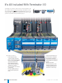
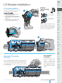
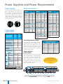
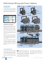
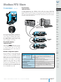
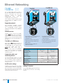
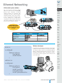
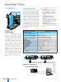
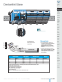
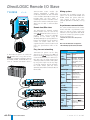
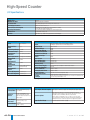
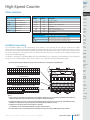
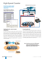
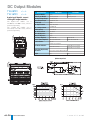
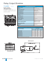
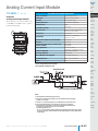
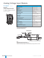
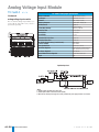
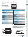
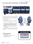
1
In this interactive PDF
you can:
• Use bookmarks to
navigate by product
category
• Use bookmarks to
save, search, print
or e-mail the catalog
section
Field I/O
Section 8
• Click on part #s
to link directly to
our online store for
current pricing, specs,
stocking information
and more
Field I/O
w w w. a u to m at i o n d i re c t . c o m
Universial Field I/O
e8–1
The Practical Field I/O System:
All the Best Features at an
AutomationDirect Price
PC-based Controls
Terminator I/O
What is it?
Terminator I/O is the most practical distributed Field I/O system
you can buy. It combines the I/O points with their field terminations into a modular package to save panel space and money.
With Terminator I/O, you can distribute I/O nodes close to field
devices for faster and more efficient wiring and troubleshooting.
Terminator I/O was custom-designed for us by Koyo (the same
people who designed the original GE Series One PLC), a trusted
name in control technology since 1983.
What’s it got?
• Network interface modules supporting Ethernet, PROFIBUSTM,
DeviceNetTM, Modbus and Koyo remote I/O; some adapters include an
on-board RS-232 serial port.
• Discrete and analog I/O modules with modular
terminal bases.
• Configuration flexibility by
plugging together a network
interface module with up to
16 I/O modules. Use local
expansion for large I/O drops.
No more confining I/O bases.
• AC or DC power supplies.
For high power systems,
combine multiple supplies on
a single I/O set.
--• Horizontal or vertical DIN-rail mounting
Ethernet
DeviceNet TM
Modbus®
PROFIBUS TM
Koyo remote I/O
What can I do with it?
• Use Terminator I/O as robust PLC remote
I/O with triple stack terminal bases and
hot-swap I/O modules.
• Add Terminator I/O to Allen-Bradley,
Siemens, Modicon or GE systems for 1/2 to 1/3 the price
of their comparable field I/O products.
• Use Terminator I/O as low-cost field I/O for your SCADA,
PC-based control system or WinPLC™ system.
Modular I/O
Terminator I/O allows you to connect serial devices, like an operator interface panel,
along with your I/O, so there’s no need to purchase adapters or run additional wiring*.
* Serial communication options available on T1H-EBC, T1K-RSSS, and T1K-DEVNETS only
16-module system with multiple power supplies
e8–2
Universial Field I/O
1 - 80 0 - 633 - 0405
Terminator I/O
PLC Control
Company
Info.
PLCs
Field I/O
Distributed Control
Software
C-more &
other HMI
AC Drives
AC Motors
Power
Transmiss.
Steppers/
Servos
Motor
Controls
Proximity
Sensors
Photo
Sensors
Limit
Switches
Encoders
Current
Sensors
Pressure
Sensors
Temp.
Sensors
Pushbuttons/
Lights
Process
Relays/
Timers
Comm.
Terminal
Blocks &
Wiring
Terminator I/O
Terminal connectors
Output modules have
replaceable fuses
Power
Circuit
Protection
L
Terminator I/O includes specialty modules like our 16-channel RTD
temperature module (T1F-16RTD) and the counter module (T1H-CTRIO)
Add additional power
module where needed
Enclosures
A L
O C
EXPA
NSI
ON
Modules slide into the
modular terminal bases.
Plug together any combination
of modules and power
sources for your application.
Tools
Pneumatics
Appendix
Part Index
D
RT ture
a
tempedrules
mo
ter
Comuondule
w w w. a u to m at i o n d i re c t . c o m / f i e l d I O
Universial Field I/O
e8–3
It’s All Included With Terminator I/O
Terminator I/O combines all the features of terminal blocks and
I/O modules into one convenient package. We took the proven
I/O technology of the DirectLOGIC DL205/405 PLC families and
combined it with a modular terminal block base to create the most
practical I/O solution for any automation project.
Terminator I/O features:
• Lower installed cost than
conventional I/O and terminal
blocks; even reduces panel space
by 30% over an equivalent DL205
system with terminal blocks.
• Easy troubleshooting at the
device termination, with status
and blown fuse indicators.
• No-tools installation and removal
of I/O modules
• Hot-swap capability helps you
get your system operating in a
hurry.
e8–4
Universial Field I/O
(
+
Modular I/O
=
Terminal
connectors
Terminator I/O
)
• Triple-stack terminal blocks for
three-wire devices, integrated
bussed power and common
terminals, plus fused outputs are
all integrated into the Terminator
package.
• Fast to install and wire,
Terminator I/O saves you time
and money. Typically no need
for additional terminal blocks,
fuse blocks or external relays.
1 - 80 0 - 633 - 0405
Pick Your Pieces and Drop ‘em In
Two sizes of terminal bases
accommodate
all I/O modules
• Half-size bases for modules with up to
8 points (T1K-08B, T1K-08B-1)
• Full size bases for modules with up to
16 points (T1K-16B, T1K-16B-1)
• Triple-stack terminal blocks standard,
easy to connect multi-wire devices
• Same bases for all I/O modules AC, DC, and analog
• Screw and spring clamp terminals
Company
Info.
Network interface modules
for your favorite fieldbus
• Ethernet - the “common sense network”,
10Base-T , 10/100Base-T ,
DeviceNet, Modbus,
Koyo remote I/O, even Profibus
-• All network modules include on-board
RS-232 serial port with varied support for
operator interfaces, bar code readers, printers
or other serial devices (check specific network
adapter specifications)
Power supplies freedom of choice,
freedom to expand
• DC power supplies (T1K-01DC),
AC versions also
(T1K-01AC)
• AC supplies include 24 VDC auxiliary
supply for convenient field device
wiring
• Need more power for high current
devices or modules? Just add another
power supply before the next
modules in the system!
Analog modules
at a super low price
per channel
8-channel I/O
16-channel I/O
Four types of 8-channel I/O
Four types of 16-channel I/O
Two types of combination I/O
Thermocouple and RTD modules
• 8-channel input modules
--• 16-channel output modules
--• 0-20mA/4-20 mA and unipolar/bipolar
voltage models available
• 14-channel thermocouple module
--(T1F-14THM)
• Hot-swap analog modules
for fast system maintenance
Specialty modules
• Counter module with pulse out
(T1H-CTRIO)
Local expansion - up to
two additional rows
• Full backplane expansion through cables
• Connect up to 16 modules across three
total rows by plugging expansion cables
from the side of one module to the side
of the next. The system automatically
recognizes the I/O.
• Optional cable that includes 24 VDC pins
maximizes your power supply capability
w w w. a u to m at i o n d i re c t . c o m / f i e l d I O
PLCs
Field I/O
Software
C-more &
other HMI
AC Drives
AC Motors
Power
Transmiss.
Steppers/
Servos
Motor
Controls
Proximity
Sensors
Photo
Sensors
T1H-EBC100
Ethernet
T1H-EBC
Ethernet
T1H-PBC
PROFIBUSTM
Limit
Switches
Encoders
Current
Sensors
Pressure
Sensors
T1K-DEVNETS
DeviceNetTM
T1K-MODBUS
Modbus®
T1K-RSSS
Koyo remote I/O
Pushbuttons/
Lights
Discrete I/O with the
features you need
Process
• 8-point input modules
--• 16-point I/O
8-point I/O
--• All DC input modules are
sink/source jumper
configurable
• Diagnostic LEDs for blown
fuse and 24 VDC power on
16-point I/O
applicable modules
• Hot-swap capability makes troubleshooting easy
e
odul
se m
r
to-u lever fo p”
y
s
Ea tion
-swa
t
c
o
e
h
j
e
nt “ ity
enie
il
conv capab
Temp.
Sensors
Easy-access
replaceable fuses on
all discrete output
modules
Relays/
Timers
Comm.
Terminal
Blocks &
Wiring
Power
Circuit
Protection
Enclosures
Tools
Pneumatics
Appendix
Part Index
Universial Field I/O
e8–5
We tried to think of everything
to make your installation easier.
When wiring a Terminator I/O system, you'll see that the little
extras make a big difference. Features like versatile half and
full-size I/O modules, standard triple-stack terminal bases
for all I/O modules, and bussed 24 VDC power through the
backplane (for DC input devices) will make your installation
Company
Info.
PLCs
Field I/O
quicker and cleaner than any comparable I/O system. Other
features include an RS-232 serial port on selected network
interface modules and replaceable fuses integrated into all
discrete output modules. Try to find that on Allen-Bradley’s Flex
I/O!
Software
C-more &
other HMI
AC Drives
AC Motors
Local expansion of up to
two rows (16 total modules)
Six interface choices
Serial port included
Power
Transmiss.
Steppers/
Servos
Half and full-size modules
irect’s
D
n
o
i
t
a
Autom
Motor
Controls
Proximity
Sensors
Photo
Sensors
Limit
Switches
Encoders
Separate power
supply
Current
Sensors
Fused outputs
standard
24 VDC through
backplane
Auxiliary 24 VDC
terminals
Pressure
Sensors
Temp.
Sensors
Triple stack terminals standard
Pushbuttons/
Lights
Process
Relays/
Timers
Comm.
®
Allen-Bradley Flex I/O
No serial port
Terminal
Blocks &
Wiring
Power
One size module only
Local expansion of up to one
row (8 total modules)
Circuit
Protection
Enclosures
Tools
Pneumatics
Appendix
Part Index
Power supply and
Interface module only
sold as integrated unit
Inconvenient
24 VDC jumpers
w w w. a u to m at i o n d i re c t . c o m / f i e l d I O
Optional three-row
terminal base
Fusing requires
special terminal base;
only 8-point low density
available
Universial Field I/O
e8–7
Just a few applications where
Terminator I/O fits
Company
Info.
PLCs
Field I/O
Software
PLC systems
C-more &
other HMI
Terminator I/O, with its variety of DC and AC discrete, analog, analog-combination and specialty modules, fills the need for distributed I/O in any size PLC
system. An Ethernet Remote Master (H2-ERM or H4-ERM) from a DL205 or
DL405 series PLC, paired with an Ethernet Base Controller (T1H-EBC(-100)) at
remote I/O locations can supply you with up to a maximum of sixteen Terminator
I/O nodes per Ethernet Remote Master channel. With hot-swappable modules
and each node capable of handling hundreds of I/O points, Terminator I/O
increases the capability of the PLC system you're already using, at a price that
won't push the budget of your project.
AC Drives
AC Motors
Power
Transmiss.
Use the E-SW050U
Ethernet Switch for
deterministic
Ethernet control for
your application.
Steppers/
Servos
Motor
Controls
PLC systems
SCADA systems
Terminator I/O can provide great low-cost I/O for your SCADA (Statistical
Control and Data Acquisition) system. For example, a PC running KEPDirect
Ethernet I/O OPC Server can monitor and control your distributed I/O via an
Ethernet Base Controller (T1H-EBC(-100)). Terminator I/O is also offered
with DeviceNet, Modbus and Profibus interfaces. Terminator I/O’s convenient,
modular terminal bases are perfect for your remote I/O locations. Terminator
I/O’s slim profile and optional panel or DIN-rail mounting make it easy to
install and wire the perfect combination of I/O in small junction boxes or
other tight spaces close to your field devices.
Proximity
Sensors
Photo
Sensors
Limit
Switches
Encoders
Current
Sensors
Pressure
Sensors
Temp.
Sensors
SCADA Systems
Pushbuttons/
Lights
Process
PC-based control systems
Relays/
Timers
Terminator I/O is the clear choice for PC-based control I/O systems.
Choose a network interface module and the I/O modules to meet your
application's needs. Terminator I/O is compatible with several PC-based
control packages, including Think & Do Studio and Think & Do Live! flowchart-based control software. Choose Think & Do Live!, add one of our
industrial monitors to your PC, and you have a PC control system that is
Ethernet-ready to connect to Terminator I/O.
Comm.
Terminal
Blocks &
Wiring
Power
PC-based control systems
Circuit
Protection
Enclosures
Tools
Pneumatics
WinPLC systems
Appendix
Terminator I/O is the perfect remote I/O complement to our technology-leading WinPLC Windows CE-based controllers. Simply install
an H2-ERM (Ethernet Remote Master) module into your DL205
WinPLC system and you can control up to sixteen modules (NOTE: one
EBC per ERM) of remotely located Terminator I/O. The 10/100 MB
Ethernet speed ensures fast I/O updates over long distances, and
convenient standard RJ45 receptacles make system cabling simple
with off-the-shelf parts.
Hybrid control system
w w w. a u to m at i o n d i re c t . c o m / f i e l d I O
Universial Field I/O
e8–9
Part Index
Terminator I/O
Terminator I/O combines all the features
of terminal blocks and I/O modules into
one convenient package.
One of the best features of Terminator I/O
is its connectivity. We offer a choice of five
plug-compatible
network
interface
modules to connect you to your choice of
network.
Achieve maximum system flexibility with
our DIN rail mountable Terminator I/O
system. Shorten wiring runs by locating
I/O near field devices. Add modules in
the future without buying new bases.
Each system needs at least one AC or DC
power supply, but you can add more
power if you need it. And, we offer a wide
variety of discrete and analog I/O
modules.
How it works:
Our removable I/O modules connect
internally to three-tier spring clamps or
screw-type terminal blocks.
Building a system
from Terminator I/O
components
With Terminator I/O, you mount just the
I/O modules you need to your DIN rail (or
you can panel-mount them). You are not
limited by a fixed base size. And you can
choose any compatible PC, PLC or other
fieldbus network master.
You’ll save the cost of separate terminal
blocks (and save the labor required to
wire from traditional PLC I/O to separate
terminal blocks). Maybe you need fused
outputs? We offer those, too!
les
6 modu
Up to 1 orizontally
h
d
mounte rtically
or ve
e8–10
Universial Field I/O
1 - 80 0 - 633 - 0405
Terminator I/O
Company
Info.
PLCs
Field I/O
Software
C-more &
other HMI
AC Drives
Terminator I/O
junction Box
AC Motors
d pair
Twiste able
c
network
Power
Transmiss.
Steppers/
Servos
Motor
Controls
Proximity
Sensors
Photo
Sensors
Terminator I/O
junction box
Limit
Switches
Network
master controller:
PC, PLC, other.
Terminator I/O
junction box
Encoders
Current
Sensors
Pressure
Sensors
I/O module addressing
Up to two rows of
local expansion
Local expansion
Terminator I/O systems can contain up to
16 modules per node. Each node can be
divided into two rows of local expansion
(1 network interface base + 2 expansion
bases) to accommodate flexible panel
space requirements in remote junction
boxes. Terminator I/O can be mounted
either horizontally or vertically.
Terminator I/O module addressing
will be different depending on which
network interface protocol is used.
For example, DeviceNet™ and
PROFIBUS™ support “word” data
types for mapping analog modules.
For Koyo remote I/O, only discrete
(“X” inputs, “Y” outputs) data types
are supported, and mapping analog
modules is accomplished in blocks of
32 I/O points per channel. Each of
the following I/O module specification pages includes an entry for
number of I/O points (bits) per
module.
Temp.
Sensors
Pushbuttons/
Lights
Process
Relays/
Timers
Comm.
Terminal
Blocks &
Wiring
Power
Circuit
Protection
Enclosures
Tools
Pneumatics
Appendix
Part Index
w w w. a u to m at i o n d i re c t . c o m / f i e l d I O
Universial Field I/O
e8–11
Dimensions and Installation
It is important to understand the installation requirements for your Terminator I/O
system. This will ensure that the Terminator
I/O products work within their environmental and electrical limits.
See the Enclosures section
for an enclosure that may be
suitable for your application
Plan for safety
This catalog should never be used as a
replacement for the technical data sheet
that comes with the products or the
T1K-INST-M Installation and I/O Manual
(available
online
at
www.automationdirect.com.) The technical
data sheet contains information that must
be followed. The system installation should
comply with all appropriate electrical
codes and standards.
Unit dimensions and
mounting orientation
Use the following diagrams to make sure
the Terminator I/O system can be installed
in your application. Terminator I/O units
should be mounted horizontally. To ensure
proper airflow for cooling purposes, units
should not be mounted upside-down. It is
important to check the Terminator I/O
dimensions against the conditions
required for your application. For
example, it is recommended to leave 2”
depth for ease of access and cable clearance. However, your distance may be
greater or less. Also, check the installation
guidelines for the recommended cabinet
clearances.
48mm
(1.89in)
e8–12
32°F to 131°F (0°C to 55°C)
Atmosphere
No corrosive gases. The level of environmental
pollution = 2 (UL 840)
Vibration Resistance
Shock Resistance
Voltage Withstand (Dielectric)
Insulation Resistance
MIL STD 810C, Method 514.2
Universial Field I/O
5% to 95% (Non-condensing)
MIL STD 810C, Method 516.2
1500 VAC, 1 minute
500 VDC, 10 M
Noise Immunity
Agency Approvals
UL, CE, FCC class A, NEC Class 1 Division 2
48mm
(1.89in)
80mm
(3.15in)
Network Interface Module
-4°F to 158°F (-20°C to 70°C)
NEMA ICS3-304
Impulse noise 1µs, 1000 V
FCC class A
RFI (144 MHz, 430 MHz 10 W, 10 cm)
48mm
(1.89in)
80mm
(3.15in)
Power Supply
Terminator I/O Environmental Specifications
Ambient Operating Temperature
Storage Temperature
Ambient Humidity
89mm
(3.5in)
80mm
(3.15in)
Half-size I/O Module
with Base
83.3mm
(3.28in)
80mm
(3.15in)
Full-size I/O Module
with Base
System Depth
1 - 80 0 - 633 - 0405
I/O Module Installation
Company
Info.
Terminator I/O modules feature separate
terminal bases for easy installation.
PLCs
DN-ASB-1
angled mounting
bracket
I/O module installation
1
To install I/O modules:
1. Slide the module into its terminal base
(until it clicks into position)
2. Hook upper DIN rail tabs over the top of
DIN rail, and press the assembly firmly onto
the DIN rail.
3. Slide the module along the DIN rail until it
engages with the adjacent module.
Field I/O
Software
Great for mounting
in upper locations
C-more &
other HMI
AC Drives
AC Motors
Great for mounting
in lower locations
Power
Transmiss.
Steppers/
Servos
Optional angled support bracket
raises and tilts the mounting rail for
easier access and wiring. Use with 35
mm DIN rail. See the Connection
Systems in this catalog for details.
2
Motor
Controls
Proximity
Sensors
Photo
Sensors
Limit
Switches
Encoders
3
Current
Sensors
Pressure
Sensors
Temp.
Sensors
Pushbuttons/
Lights
Process
Relays/
Timers
Comm.
Removing I/O modules
is a snap
Grip the locking handle, as shown, and pull gently to
eject the I/O module from its base. The module will slide
out for easy replacement. This procedure does not apply
to network interface modules or power supplies, which
have integral bases.
Hot-swappable
I/O modules
You can remove I/O
modules under power, but
exercise
caution while
doing so. Do not touch the
terminals with your hands or
any conductive material.
Always remove power when
possible.
Terminal
Blocks &
Wiring
Power
Circuit
Protection
Enclosures
Tools
Pneumatics
Appendix
Part Index
w w w. a u to m at i o n d i re c t . c o m / f i e l d I O
Universial Field I/O
e8–13
Power Supplies and Power Requirements
Power supplies
Power requirements
The Terminator I/O product line offers two
power supply options: AC or DC. The
power supplies are always positioned to
the left of the modules to which they
supply power. Consult the system configuration examples and the power budgeting
example for more information on positioning power supplies.
Module
5VDC 24VDC
Interface Modules
DC Output Modules
200
0
T1F-08AD-1
75
50*
T1H-EBC100
300
0
T1K-08TD1
100
200*
T1F-08AD-2
75
50*
T1H-PBC
530
0
T1K-16TD1
200
400*
T1F-16AD-1
75
50*
T1K-DEVNETS
250
45
T1K-08TD2-1
200
0
T1F-16AD-2
75
50*
T1K-RSSS
250
0
T1K-16TD2-1
200
0
T1F-14THM
60
70*
T1K-MODBUS
300
0
AC Output Modules
T1F-16RTD
150
0
250
0
Analog Output Modules
T1K-08ND3
35
0
T1K-16TA
450
0
T1F-08DA-1
75
75*
T1K-16ND3
70
0
T1K-08TAS
300
0
T1F-08DA-2
75
75*
Relay Output Modules
T1F-16DA-1
75
150*
75
150*
T1K-08NA-1
35
0
T1K-08TR
350
0
T1F-16DA-2
T1K-16NA-1
70
0
T1K-16TR
700
0
Combination Analog Modules
T1K-08TRS
400
0
T1F-8AD4DA-1
75
60*
T1F-8AD4DA-2
75
70*
Specialty Modules
T1K-01DC
<--->
T1K-01AC
<--->
T1K-08TA
T1H-CTRIO
To calculate the power budget, read the
available power (current rating) from the
Power Supply Specifications table and
subtract the power consumed by each
module to the right of the power supply.
Do not include modules to the right of an
additional power supply.
30 W
Max. Inrush Current 20 A
10 A
Insulation
Resistance
> 10 M @ 500 VDC
Voltage Withstand
1 min. @ 1500 VAC between
primary, secondary and field
ground
Voltage
5VDC
PWR
5.25 VDC
5.25 VDC
2000 mA max
current
Current Rating (see
option note 2000 mA max
below)
Ripple
5% max.
5% max.
Voltage
24 VDC
N/A
300 mA max.
24VDC Current Rating (see current
option note
PWR
N/A
below)
Ripple
Fuse
10% max.
400
0
* Use either internal or external source
for 24VDC
* Use either internal or external source
for 24VDC
Input Frequency
Maximum Power
50 VA
Analog Input Modules
T1H-08TDS
Calculating the power budget
N/A
5VDC 24VDC
0
Input Voltage Range 110/220 VAC 12/24 VDC
50/60 Hz
Module
350
AC Input Modules
Power Supply
Specifications
5VDC 24VDC
T1H-EBC
DC Input Modules
Power supply
specifications
Module
Adding additional
power supplies
Each power supply furnishes power only
to the network interface and I/O modules
to its right. Inserting a second power
supply closes the power loop for the
power supply to the left, while also
powering the modules to its right. Perform
a power budget calculation for each
power supply in the system.
Power Budget Example
Module
5VDC
24VDC
T1K-01AC
+2000 mA
+300 mA
T1H-EBC
-350 mA
-0 mA
T1K-16ND3
-70 mA
-0 mA
T1K-16TD2
-200 mA
-0 mA
T1F-08AD-1
-75 mA
-50 mA
Remaining
+1305 mA
+250 mA
Accessories available for
Terminator I/O are listed in the
Terminator Field I/O section of the
Price List
N/A
1 (primary), not replaceable
Note: 500 mA @ 24 VDC can be achieved by lowering
the 5VDC from 2000 mA to 1500 mA .
This power supply powers the network interface module and This power supply powers these three I/O
the next two I/O modules
modules
e8–14
Universial Field I/O
1 - 80 0 - 633 - 0405
Expansion I/O Configurations
T1K-05CBL-LL
T1K-05CBL-LL-1*
Left side to left side
expansion cable
Expansion cables
T1K-10CBL
<--->
T1K-10CBL-1* <--->
Right side to left side
expansion cable
The T1K-10CBL(-1) connects the right side
of an I/O base to the left side of the next
I/O base. A maximum of two
T1K-10CBL(-1) cables can be used per
expansion system.
<--->
<--->
Company
Info.
T1K-05CBL-RR
<--->
T1K-05CBL-RR-1*
<--->
Right side to right side
expansion cable
The T1K-05CBL-LL(-1) connects the left
side of an I/O base to the left side of the
next I/O base. Only one T1K-05CBL-LL
(-1) cable can be used per expansion
system and must be used with a
T1K-05CBL-RR(-1) cable. This cable cannot
be connected to the left side of the network
interface base.
The T1K-05CBL-RR(-1) connects the
right side of an I/O base to the right
side of the next I/O base. A
maximum of one T1K-05CBL-RR(-1)
cable can be used per expansion
system. Note: When this cable is
used, the expansion I/O assignments
are from right to left (reversed).
PLCs
Field I/O
Software
C-more &
other HMI
AC Drives
AC Motors
Power
Transmiss.
Steppers/
Servos
Motor
Controls
Cable length = 1.0m
Cable length = 0.5m
Cable length = 0.5m
Proximity
Sensors
Photo
Sensors
*Note: The (-1) versions of the expansion cables pass 24 VDC through on an isolated wire. (All cables pass the 5 VDC base power.)
Any local expansion DC input module configured for “internal power” (current sourcing) must either have a power supply preceding
it on the same base or, have a (-1) version cable pass 24 VDC from a power supply on the preceeding base.
Using two T1K-10CBL expansion cables
Pressure
Sensors
Power supplies can be used anywhere in the first two bases,
but not in the last expansion base.
T1K-10CBL(-1)
Encoders
Current
Sensors
Using T1K-10CBL expansion cable
and T1K-05CBL-RR expansion cable
In the system below, power supplies can be used anywhere.
Limit
Switches
Temp.
Sensors
Pushbuttons/
Lights
I/O Addressing
A power supply can be
used on either base.
I/O Addressing
Process
T1K-10CBL(-1)
Relays/
Timers
T1K-10CBL(-1)
Comm.
A power supply cannot be
used on a base that is
connected to a system by
a T1K-05CBL-RR(-1).
T1K-05CBL-RR(-1)
See Note above
Terminal
Blocks &
Wiring
Power
Using T1K-05CBL-RR expansion cable
and T1K-05CBL-LL expansion cable
Circuit
Protection
Using T1K-05CBL-RR expansion cable
Power supplies can be used anywhere in the first and third
bases, but not in the second base.
Power supplies can be used anywhere in the first base, but not
in the second base.
Enclosures
Tools
Pneumatics
Do not connect a
T1K-05CBL-LL(-1) to
the left side of the
network interface base.
T1K-05CBL-LL
Appendix
I/O Addressing
I/O Addressing
T1K-05CBL-RR(-1)
See Note above
T1K-05CBL-RR(-1)
See Note above
A power supply cannot be
used on a base that is
connected to a system by
a T1K-05CBL-RR(-1).
w w w. a u to m at i o n d i re c t . c o m / f i e l d I O
A power supply cannot be
used on a base that is
connected to a system by
a T1K-05CBL-RR(-1).
Universial Field I/O
e8–15
Part Index
Field Device Wiring and Power Options
Terminal base
specifications
T1K-08B <--->
T1K-08B-1 <--->
Terminator I/O terminal bases are available in
screw clamp and spring clamp versions for both
half-size and full-size modules. Hot stamp
silkscreen labeling is used for numbering I/O
points, commons, and all power terminals.
Spring clamp, half-size
Screw clamp, half-size
Terminal Base Specifications
Terminal Type
Screw type
Recommended 1.77-3.54 lb-in
(0.2 - 0.4 Nm)
Torque
Wire Gauge
Solid:
25-12 AWG
Stranded:
26-12 AWG
T1K-16B <--->
T1K-16B-1 <--->
Spring clamp
n/a
Solid:
25-14 AWG
Stranded:
26-14 AWG
Spring clamp, full-size
Screw clamp, full-size
Field device wiring options
Power your DC input devices from the
integrated 24 VDC power supply bus.
T1K-08ND3 and T1K-16ND3 DC input
modules include jumpers for selecting the
internal 24 VDC power supply available
for 2- and 3-wire field devices. Clearly
labeled triple stack terminals make it easy
to wire 2- and 3-wire devices ensuring
clean wiring with only one wire per
termination.
2 and 3-wire DC input devices
using bussed 24 VDC power
External user supplied 24 VDC power, or
auxiliary 24 VDC terminals from T1K-01AC,
can be easily applied directly to one end of
the terminal rows and jumpered across each
base in the system.
This is a convenient solution for powering
analog I/O and discrete DC output
devices whose modules do not have direct
access to the internal bussed 24 VDC. If
current consumption increases, simply add
additional T1K-01AC power supplies into
the system.
Use externally supplied 24 VDC
power or 24 VDC auxiliary power
from T1K-01AC
Do not jumper modules together
to create a 24 VDC bus when
using the “hot swap” feature.
See Note below.
Hot-swap feature
The hot-swap feature allows Terminator
I/O modules to be replaced while system
power is on. Be careful not to touch the
terminals with your hands or other conductive material to avoid the risk of personal
injury or equipment damage. Always
remove power if it is equally convenient to
do so.
e8–16
Universial Field I/O
Note: Before hot-swapping analog or DC
output modules in a Terminator I/O
system, make sure that each of the analog
and DC output module’s 24 VDC and 0
VDC base terminals are wired directly to
the external power supply individually. If
the external 24 VDC and 0 VDC is
jumpered from base to base in a daisy
chain fashion, and an analog or DC
output module is removed from its base,
the risk of disconnecting the external 24
VDC and 0 VDC to the subsequent I/O
modules exists.
1 - 80 0 - 633 - 0405
Modbus RTU Slave
T1K-MODBUS <--->
Company
Info.
PLCs
Asynchronous
communications
Field I/O
In most applications, the Modbus master polls the slaves individually
(T1K-MODBUS) to read/write each slave’s I/O. The communication between the
Modbus master and slave will often be asynchronous to the master CPU scan. For
this reason, applications should be limited to those that do not require the I/O points
to update every master CPU scan.
Software
C-more &
other HMI
AC Drives
AC Motors
Power
Transmiss.
Steppers/
Servos
OR
Motor
Controls
Any PLC or PC
MODBUS RTU master
Proximity
Sensors
Photo
Sensors
Limit
Switches
The Terminator I/O Modbus network interface module allows you to connect I/O as
a slave station on a Modbus RTU network.
The T1K-MODBUS can communicate with
any Modbus RTU network master using
high-level Modbus commands.
Encoders
Current
Sensors
T1K-MODBUS
slaves
Pressure
Sensors
Temp.
Sensors
DirectLOGIC Modbus
communications
Pushbuttons/
Lights
Some of our DirectLOGIC PLCs can be
used as Modbus masters, directly through
a communication port on the CPU.
(Consult the PLC section of this catalog for
more information.)
Process
Relays/
Timers
Comm.
Network configuration options
You can configure a simple point-to-point
network or create a multidrop network
using the RS-232, RS-422/485 HD-15
Modbus port. The T1K-MODBUS has two
rotary switches that can be set to designate
the module’s slave address. Set the rotary
switches to give each slave a unique
address in a range from 1-F7 hex (1-247
decimal). The T1K-MODBUS also has an
auxiliary RJ12 RS-232 serial port that can
be used to configure the Modbus port with
the T1K-MODBUS Setup Tool.
Terminal
Blocks &
Wiring
Specifications
Modbus
Port
RS-232
15 m (50 ft.): 300, 600, 1200, 2400, 4800, 9600; 19.2 K, 38.4 K baud
Cable Lengths
and Baud Rates RS-422/485 1000 m (3300 ft): 300, 600, 1200, 2400, 4800, 9600; 19.2 K,
38.4 K baud
Power
Circuit
Protection
Max. I/O Points per Controller
Discrete: inputs: 1024, outputs: 1024;
Analog: inputs: 64 channels, outputs: 64 channels
Recommended Cable
Belden 9729 or equivalent (RS-422)
Terminal Type
15-pin female high-density (VGA style) D-sub connector
RJ12 Serial Port
RS-232; 9600/19200 baud; supports K-Sequence and ASCII
(Use to configure Modbus port using T1K-MODBUS setup tool)
Pneumatics
Base Power Requirement
250 mA @ 5 VDC
Appendix
Enclosures
Tools
Part Index
w w w. a u to m at i o n d i re c t . c o m / f i e l d I O
Universial Field I/O
e8–17
Ethernet Networking
T1H-EBC
T1H-EBC100
<--->
<--->
T1H-EBC100
T1H-EBC
The T1H-EBC(100) modules provide a
low-cost, high-performance Ethernet link
between Terminator I/O and your
PC-based
control
or
WinPLC/
DL205/DL405
CPUs
using
the
H*-ERM module for remote I/O.
T1H-EBC100
These interface modules support industry
standard 10Base-T or 100Base-T communications.
Supported protocols
The Terminator T1H-EBC supports
UDP/IP and IPX at 10 Mbps maximum.
The T1H-EBC100 supports TCP/IP,
UDP/IP, IPX and Modbus TCP at 100 Mbps
maximum.
Network masters
Network masters include the DL205,
DL405 DirectLOGIC PLCs and WinPLCs
using the Ethernet Remote Master module
(ERM), and PCs using PC-based control
software that includes embedded Ethernet
I/O drivers.
• Save money on your Terminator I/O
system when compared with
competitive I/O
• Virtually unlimited number of I/O
points (up to sixteen modules per
EBC system)
• Deterministic I/O updates on
dedicated networks
T1H-EBC as H*-ERM slave
When using a DirectLOGIC CPU with an
ERM module as the network master, the
T1H-EBC(100) slave will provide faster
analog I/O update times than a
DirectLOGIC CPU system with a
T1K-RSSS slave system. The ERM/EBC
system can also support a much higher
analog I/O count than the T1K-RSSS
remote I/O system.
Inexpensive cables and
connecting devices
The Terminator EBC modules are made
with industry standard RJ45 connections
for easy networking. Off-the-shelf Ethernet
hubs and repeaters make configuring a
network a breeze.
No DIP-switch settings
All addressing and setup features are configurable through the software configuration
tool. All I/O data are passed into the EBC
buffer and communicated as a block almost
instantaneously to the host device.
e8–18
Universial Field I/O
Specifications
• Use off-the-shelf networking
components to connect to your
existing network
• Fast I/O updates of <1 ms per base
• On-board serial port for operator
panel or ASCII devices
T1H-EBC
T1H-EBC100
Communications
Data Transfer Rate
Link Distance
Ethernet Port
10Base-T Ethernet
100Base-T Ethernet
Ethernet Protocols
UDP/IP, IPX
TCP/IP, UDP/IP, IPX,
Modbus TCP
350 mA
300 mA
Power Consumption
Manufacturer
RJ12 Serial Port 1
10 Mbps
10/100 Mbps
100 meters (328 ft.)
RJ45
Host Automation Products, L.L.C.
K-sequence, ASCII
K-sequence, ASCII, Modbus RTU
1 At
this time, the serial port is unavailable when these modules are used as slave devices to the H2-ERM or
H4-ERM modules.
Adding I/O modules
The T1H-EBC(100) supports the full lineup
of Terminator I/O discrete and analog
modules.
1 - 80 0 - 633 - 0405
Ethernet Networking
Company
Info.
PLCs
Off-the-shelf system solutions
Field I/O
You can purchase PC-based control
software to connect to our T1H-EBC(100)
Ethernet Base Controller. PC-based
control packages are equipped with
compatible I/O device drivers, program
development tools, and run-time environments. See the PC-based Control section
of this catalog for a single-source
integrated PC-based control solution that
ships with everything you need to make
your PC into an industrial controller.
Software
C-more &
other HMI
AC Drives
AC Motors
Power
Transmiss.
Steppers/
Servos
Motor
Controls
E-SW05-U Ethernet Switch
(See the Communications
Products section of this catalog
for details).
Proximity
Sensors
Photo
Sensors
Vendor
Product
Limit
Switches
Web Address
AutomationDirect
KEPDirect EBC I/O Server
www.automationdirect.com
Encoders
Phoenix Contact
Think and Do Live!
Think and Do Studio
www.phoenixcon.com/software
Current
Sensors
KEPWare
KEPServerEX
www.kepware.com
MDSI
Open CNC
www.mdsi2.com
Pressure
Sensors
Temp.
Sensors
Pushbuttons/
Lights
READ I/O
int HEIReadIO
(
HEIDevice *pDevice,
Byte *pBuffer,
WORD BuffSize
);
Software developers
Process
For programmers developing custom drivers for our I/O,
we offer a free Ethernet Software Development Kit (SDK).
The software interface libraries are provided for WIN32,
WIN16, and DOS operating systems. The source code is
available to developers under a non-disclosure agreement. Visit the technical support link at our Web site for
more information.
Relays/
Timers
Comm.
Terminal
Blocks &
Wiring
Power
Circuit
Protection
WRITING I/O
Enclosures
Tools
int HEIWriteIO
(
HEIDevice *pDevice,
BYTE *pData,
WORD SizeofData,
BYTE *pReturnData,
WORD *pSizeofReturnData
);
w w w. a u to m at i o n d i re c t . c o m / f i e l d I O
Pneumatics
Appendix
Part Index
Universial Field I/O
e8–19
PROFIBUS™ Slave
T1H-PBC
<--->
TM
PROFIBUS I/O
system overview
If you are using a PROFIBUS™ controller
network, the Terminator I/O sub-system
will help further reduce the cost of your
overall application. The T1H-PBC module
allows the micro-modular Terminator I/O
sub-system to be linked with a PROFIBUS
master controller. PROFIBUS is a control
bus that provides a common method to
connect automation equipment with
devices on a single network. This standard
communications media is referred to as
PROFIBUS and significantly reduces hardwiring costs. PROFIBUS provides specifications for information exchanged
between nodes, such as controller data
associated with low- level device and
configuration parameters individually
related to system operations.
PROFIBUS allows 32 stations per segment.
Segments vary in length depending on the
desired transmission speed. The maximum
speed is achieved on a segment 100
meters (327 feet) in length. Our
PROFIBUS-DP Slave represents a single
station. Repeaters also count as stations
and are used to extend the network to
greater distances. Our PROFIBUS module
supports baud rates of 9.6 Kbaud to 12
Mbaud depending on the network length.
e8–20
Universial Field I/O
Here’s how it works:
The T1H-PBC also offers the following
features:
The T1H-PBC module is a PROFIBUS
slave, which can be plugged into the
network interface position of the
Terminator I/O micro-modular family of
I/O bases. This module reports all the
identification data, diagnostic information,
and parameters that control the module
operation. The T1H-PBC module scans
and reports all discrete and analog I/O
data to a PROFIBUS master. The externally-powered AC Terminator I/O base
units contain a 24 VDC power supply for
simple wiring of sensors and actuators into
the Terminator I/O modules, and for
controlling them with a PROFIBUS master.
Using our PROFIBUS I/O sub-system will
increase installation flexibility as well as
save on wiring costs. The T1H-PBC
module supports all Terminator discrete
and analog I/O modules.
• Cost-effective: With a single network for
devices, hardwiring costs are reduced.
• Easy connectivity: Low-cost installation is
easy to implement and maintain.
• Diagnostics: The PROFIBUS slave offers
advanced error diagnostics not
commonly available in traditional
systems.
• High baud rates: Response time is 10
ms per device
• LED Indicators: These provide quick
indication of Terminator power and
operating mode.
Specifications
Module Type
Max. Expansion
Max. I/O Points per Controller
Communications
PROFIBUS Network Interface Module
126 stations, 32 stations per segment, 9 repeaters in a row
244 Input Bytes (analog or discrete)
244 Output Bytes (analog or discrete)
as specified by the PROFIBUS DP Specification
RS-485 PROFIBUS, PROFIBUS-DP.
Baud rate selectable from 9.6 Kbaud to 12 Mbaud.
Module Connectors
Internal Power Consumption
PROFIBUS 9-pin D-shell, RJ-12 serial (for firmware update only)
Operating Environment
0ºC to 60ºC (32ºF to 140ºF), 5% to 95% humidity
(non-condensing)
Manufacturer
Host Automation Products, L.L.C.
530 mA maximum at 5 VDC (supplied by base power supply)
Please Note:
1. Terminator I/O PROFIBUS slave network interface module T1H-PBC is a PTO-certified PROFIBUS-compliant
slave I/O interface product.
See www.profibus.com for more information.
2 For use with Think & Do Software, we recommend the
SST PROFIBUS PCI Master Card, part number
5136-PFB-PCI. (AutomationDirect does not provide this
interface).
See www.mysst.com for more information.
1 - 80 0 - 633 - 0405
PROFIBUS Slave
Company
Info.
PLCs
Field I/O
H
Software
C-more &
other HMI
AC Drives
AC Motors
Power
Transmiss.
Steppers/
Servos
Male
Female
9
8
7
6
5
4
3
2
1
5
4
3
2
1
Proximity
Sensors
Photo
Sensors
Node
Termination
Max.
Expansion
Feet
Meters Feet
Meters
9.6 Kbps
3278
1000
32786
10000
19.2 Kbps
3278
1000
32786
10000
93.75 Kbps
3278
1000
32786
10000
187.5 Kbps
3278
1000
32786
10000
500 Kbps
1311
400
13114
4000
1.5 Mbps
655
200
6557
2000
3 Mbps
327
100
3270
1000
6 Mbps
327
100
3270
1000
12 Mbps
327
100
3270
1000
Discrete Types
Analog Types
8-point DC Input
8-channel Current Input
8-point AC Input
8-channel Voltage Input
16-point DC Input
8-channel Current Output
16-point AC Input
8-channel Voltage Output
8-point DC Output
16-channel Current Input
8-point AC Output
16-channel Voltage Input
16-point DC Output
16-channel Current Output
16-point AC Output
16-channel Voltage Output
8-point Relay Output
Vertical
entry cable
Horizontal entry
cable
ERNI ERbic
connectors
for
PROFIBUS
networks
Current
Sensors
Pressure
Sensors
Temp.
Sensors
Connectors are available for the
PROFIBUS Base Controller. They are
available in standard node and standard termination styles with vertical
cable entry for Terminator I/O.
Pushbuttons/
Lights
Process
Relays/
Timers
Comm.
Terminator I/O Modules Supported
Contact A
Contact B
ERNI ERbic Connectors
Terminal
Blocks &
Wiring
Power
Part
Number Price Description
103658 <--->
Shield tied
Bar
Contact A
Contact B
16-point Relay Output
103659 <--->
Recommended Cables
Siemens
Belden
Limit
Switches
Encoders
Max.
Segment
Length
Baud
Motor
Controls
9
8
7
6
6XV1 830 0AH10
Device
Terminator I/O
T1H-PBC or
PROFIBUS
any PROFIBUS
certified standard
ISA/ PCI
node
Personal
vertical connector.
Computer
9-pin male D-sub
Master/Slave
Card
Terminator I/O
T1H-PBC or
PROFIBUS
any PROFIBUS
certified standard
ISA/ PCI
termination
Personal
vertical connector
Computer
9-pin male D-sub
Master/Slave
Card
3079A
w w w. a u to m at i o n d i re c t . c o m / f i e l d I O
Universial Field I/O
e8–21
Circuit
Protection
Enclosures
Tools
Pneumatics
Appendix
Part Index
TM
DeviceNet Slave
T1K-DEVNETS <--->
Here’s how it works:
The T1K-DEVNETS module is a DeviceNet
slave. This module maintains a database
with all the identification data, diagnostic
information, and parameters that control
the module operation. The T1K-DEVNETS
module scans and reports all discrete and
analog I/O data to a DeviceNet master.
The AC power supply provides a 24 VDC
output for simple wiring of sensors and
actuators into the Terminator I/O
modules. Using our Terminator I/O
DeviceNet sub-system will increase installation flexibility as well as save on wiring
costs. The T1K-DEVNETS module supports
all Terminator I/O discrete and analog
I/O modules.
TM
The T1K-DEVNETS also offers the
following features:
• Cost-effective: With a single network for
devices, hardwiring costs are reduced.
• Easy connectivity: Low-cost four wire
installation is easy to implement and
maintain.
• Innovative technology: Power is
integrated into the device wiring.
• Diagnostics: The module provides
advanced error diagnostics not commonly
available in traditional control systems.
• Highly dependable: Fast response for
demanding applications.
• LED indicators: Provide quick indication
of Terminator I/O power and operating
mode.
General Specifications
DeviceNet I/O
system overview
If you are already using or planning to
implement a DeviceNet
controller
network, our Terminator I/O sub-system
will help further reduce the cost of your
overall application. We now offer the
T1K-DEVNETS (slave) module, which
allows our Terminator I/O sub-system to
be linked with a DeviceNet master
controller. DeviceNet is a low-cost control
network that provides a common method
to connect on a single network. This
advanced communications media and
software is referred to as DeviceNet and
significantly reduces hardwiring costs.
DeviceNet provides specifications for
information exchanged between nodes,
such as controller data associated with
low-level devices and configuration parameters individually related to system operations.
DeviceNet Compatibility
Maximum Field Devices per Bus
Predefined Group 2 master/slave communications
64 (see table next page)
Maximum I/O Points per DEVNETS
1024 input bits (analog or discrete
1024 output bits (analog or discrete
as specified by DeviceNet Slave Polling Specification
Communication to Field Devices
Standard 4-wire shielded cable to cabinet connector,
molded 4-wire cable @ up to 500Kbps to field devices
Serial Port
Module Connector
Operating Temperature
Storage Temperature
Relative Humidity
Environmental Air
Vibration
Shock
RS232C, RJ12, Protocol support: K-sequence, ASCII
Noise Immunity
NEMA ICS3-304,Impulse noise 1ms, 1000V
FCC class A, RFI (144Mhz, 430Mhz 10W, 10cm)
TM
5-position removable terminal (European style)
0 to 55°C (32 to 131°F)
-20 to 70°C (-4 to 158°F)
5 to 95% (non-condensing)
No corrosive gases permitted
MIL STD 810C 514.2
MIL STD 810C 516.2
Connect our Terminator I/O
to your DeviceNet network.
e8–22
Universial Field I/O
1 - 80 0 - 633 - 0405
DeviceNet Slave
Company
Info.
PLCs
Field I/O
Software
C-more &
other HMI
AC Drives
AC Motors
Power
Transmiss.
Steppers/
Servos
Motor
Controls
Proximity
Sensors
Photo
Sensors
Limit
Switches
Encoders
Current
Sensors
Pressure
Sensors
Please Note:
Recommended cable:
Belden 3085A, YR-29832
Temp.
Sensors
1. For use with Think & Do Software, we
recommend the SST DeviceNet PCI Master
Card, part number 5136-DNP-PCI.
(AutomationDirect does not provide this
interface). See www.mysst.com for more
information.
(or equivalent)
2. Terminator I/O DeviceNet slave network
interface module T1K-DEVNETS is an ODVA
certified DeviceNet-compliant slave I/O
interface product. See www.odva.com for
more information.
DeviceNet cable
Pushbuttons/
Lights
Process
Relays/
Timers
Comm.
Terminal
Blocks &
Wiring
Trunk Length
Comm Speed
Branch Length
Power
Devices
Feet
Meters
Baud
Feet
Meters
Maximum
328
100
500 Kbps
20
6
64
820
250
250 Kbps
20
6
64
1,640
500
125 Kbps
20
6
64
Circuit
Protection
Enclosures
Tools
Pneumatics
For other DeviceNet specifications, compatible products and latest DeviceNet information, contact:
Open DeviceNet Vendor Association
Contact: Executive Director Katherine Voss
Phone: 734/975-8840 • Fax: 734/922-0027
Internet address: http://www.odva.org
e-mail: [email protected]
ODVA, Inc. • 1099 Highland Drive, Suite A, Ann Arbor, MI. 48108
w w w. a u to m at i o n d i re c t . c o m / f i e l d I O
Appendix
Part Index
Universial Field I/O
e8–23
DirectLOGIC Remote I/O Slave
T1K-RSSS
<--->
communication master module (for
example, D2-RMSM) is added. The
remote I/O protocols are also embedded
in the D2-250-1,D2-260, D3-350, and
D4-450 CPUs. On these CPUs, a
networking connection is available via one
of the built-in communication ports so you
don’t have to add a communication
module.
Mixing systems
Remote slave/Slice slave
The communication between the remote
master and CPU is asynchronous to the
CPU scan. For this reason, remote I/O
should be used in applications that do not
require the remote I/O points to update
during every CPU scan.
The Terminator I/O T1K-RSSS network
interface module serves as a slave to any
of the DirectLOGIC PLCs that can act as a
remote
master (using the RM-NET
protocol) or slice master (using the
SM-NET protocol). The primary differences
between the protocols are the maximum
number of remote nodes that are
supported and the communication baud
rates. (See Specifications table on this
page.)
Terminator I/O (T1K-RSSS) remote I/O
systems can be mixed with DL205 and
DL405 remote I/O systems within the
same channel as long as the same
protocol (RM-NET or SM-NET) is being
used.
Asynchronous communications
1
Consult the PLC section of this catalog for more
details.
Note: The T1K-RSSS does not support the
T1H-CTRIO High-Speed Counter I/O module.
Easy, low-cost networking
A Terminator I/O system can connect to
DirectLOGIC PLCs using either of our
proprietary networking protocols. Most of
the DL205, DL305, and DL405 PLCs can
serve as a Remote I/O Master1 when a
RE M OT E I /O
MASTER
RM
Terminator I/O systems can be daisy
chained up to a distance of 3,900 feet
from the local DirectLOGIC PLC using a
recommended twisted pair communication cable. You can assign normal input
and output addresses to the remote points
by using a few simple lines of setup logic
in your RLL program. During operation,
the remote master polls the slaves
(T1K-RSSS) and sends the remote I/O status to
the PLC CPU.
Specifications
1.2 km (3900 ft): 19.2 K or
RM-NET 38.4 Kbaud
Cable
100 m (328 ft): 614.4 Kbaud
Length:
300 m (984 ft): 307.2 Kbaud
Baud Rate SM-NET 600 m (1968 ft): 153.6K baud
1,200 m (3900 ft): 19.2 K or
38.4 Kbaud
Recommended
Cable
Belden 9841 or equivalent
(120 Ohm impedance, 12pF/ft)
Terminal Type
Four-position removable
terminal
Remote
I/O
Masters
D2-RMSM, D4-RM
D2-260 15-pin port
RM-NET D2-250(-1) 15-pin port
D3-350 25-pin port
D4-450 25-pin port
SM-NET D2-RMSM
Number of Masters
per
PLC CPU
Check PLC CPU remote
I/O specifications
Max. Slave
I/O Points
per PLC CPU
Channel
Capacity
Serial
Comm
Port
RM-NET 7 slave stations
SM-NET 31 slave stations
RJ12 9600 baud RS-232
SM-NET K-sequence (for DirectSOFT
programming or operator panel
only
connection only)
Base Power
Requirement
e8–24
Universial Field I/O
250 mA
1 - 80 0 - 633 - 0405
High-Speed Counter I/O Module
Company
Info.
PLCs
CTRIO features
HIgh-Speed
Counter I/O
Module
T1H-CTRIO <--->
Overview
The High-Speed Counter I/O (CTRIO)
module is designed to accept high-speed
pulse-type input signals for counting or
timing applications and to provide highspeed pulse-type output signals for stepper
motor control, monitoring, alarm or other
discrete control functions. The CTRIO
module offers great flexibility for applications that call for precise counting or timing,
based on an input event or for high-speed
control output applications.
The CTRIO module has its own microprocessor and operates asynchronously
with respect to the PLC/controller. This
means that the on-board outputs respond
in real time to incoming signals, so there is
no delay waiting for the PLC/Controller to
scan I/O.
The CTRIO modules offer the following
I/O features:
• Eight DC sink/source inputs, 9-30 VDC
• Four isolated sink/source DC outputs,
5-30 VDC, 1A per point
Inputs supported:
• Two quadrature encoder counters up to
100 kHz, or four single-channel counters up to 100 kHz using module terminals Ch1A, Ch1B, Ch2A and Ch2B
• High-speed edge timers, dual edge
timers, pulse catch, count reset, count
inhibit , or count capture or home
search limits using module terminals
Ch1C, Ch1D, Ch2C or Ch2D
Outputs supported:
• Four independently configurable highspeed discrete outputs or two channels
pulse output control (20 Hz-25 kHz per
channel or 50 kHz if only using one
channel)
• Pulse and direction or cw/ccw pulses
supported for pulse output control
• Raw control of discrete output directly
from user control program
Software
configuration
All scaling and configuration is done via
CTRIO Workbench, a Windows software
utility program. This eliminates the need
for PLC ladder programming or other
interface device programming to set up
the module. CTRIO Workbench runs
under Windows 98/2000/XP and NT
4.0 SP5 or later.
CTRIO Workbench main configuration screen
Typical applications
• High-speed cut-to-length operations
using encoder input
• Pick-and-place or indexing functions
controlling a stepper drive
• Dynamic registration for web material
control
• Accurate frequency counting for speed
control with onboard scaling
• PLS (Programmable Limit Switch)
functions for high-speed packaging,
gluing, or labeling
• Sub 10 µsec pulse-catch capability for
high-speed product detection
• Functions for level or flow
Software
C-more &
other HMI
AC Drives
AC Motors
Power
Transmiss.
Steppers/
Servos
Motor
Controls
Supported systems
Proximity
Sensors
Multiple T1H-CTRIO modules can
reside in the same I/O system provided
that the base power budget is adequate.
Photo
Sensors
PC-based Ethernet I/O
control systems
Limit
Switches
Encoders
The T1H-CTRIO module can be used in
PC-based control systems using the
T1H-EBC(100) interface module.
PROFIBUS systems
The T1H-CTRIO module can be used in
Profibus systems using the T1H-PBC
slave interface module.
Current
Sensors
Pressure
Sensors
Temp.
Sensors
Pushbuttons/
Lights
ERM to EBC systems
Process
The T1H-CTRIO module is supported in
T1H-EBC(100) slaves in H*-ERM
systems.
Relays/
Timers
Notes:
1. The T1H-CTRIO module is not supported when
using the T1K-RSSS, T1K-MODBUS, T1KDEVNETS contoller modules.
The T1H-CTRIO module is designed to
work with incremental encoders or other
field devices that send pulse outputs.
Field I/O
2. System functions are not available when
CTRIO is used in ERM/EBC expansion I/O.
Configure I/O screen
Comm.
Terminal
Blocks &
Wiring
Power
Circuit
Protection
Enclosures
Tools
Pneumatics
Appendix
Part Index
Use Configure I/O dialog to assign
the CTRIO input and output functions
w w w. a u to m at i o n d i re c t . c o m / f i e l d I O
Universial Field I/O
e8–25
High-Speed Counter
I/O Specifications
General
Module Type
Modules Per Base
I/O Points Used
Field Wiring Connector
Internal Power Consumption
Operating Environment
Manufacturer
Isolation
Intelligent
Limited only by power consumption
None, I/O map directly in PLC V-memory or PC control access
Standard removable terminal block
400 mA Max at +5V from Base Power Supply, Maximum of 6 Watts
(All I/O in ON State at Max Voltage/Current)
32°F to 140°F (0°C to 60°C), Humidity (non-condensing) 5% to 95%
Host Automation Products, LLC
2500 V I/O to Logic, 1000 V among Input Channels and All Outputs
T1H-CTRIO Input Specifications
Inputs
Minimum Pulse
Width
Input Voltage Range
Maximum Voltage
Input Voltage
Protection
Rated Input Current
Minimum ON
Voltage
Maximum OFF
Voltage
Minimum ON
Current
Maximum OFF
Current
OFF to ON Response
ON to OFF Response
T1H-CTRIO Output Specifications
8 pts sink/source
Outputs
4 pts, independently isolated, current sourcing or sinking
FET Outputs: open drain and source with floating gate drive
5 µsec
Voltage Range
Maximum Voltage
Output Clamp Voltage
Maximum Load Current
Maximum Load Voltage
Maximum Leakage
Current
Inrush Current
OFF to ON Response
ON to OFF Response
ON State V Drop
External Power Supply
Overcurrent Protection
Thermal Shutdown
Overtemperature Reset
Duty Cycle Range
Configurable Presets
a) single
b) multiple
5 VDC - 36 VDC
36 VDC
60 VDC
1.0 A
9-30 VDC
30 VDC
Zener Clamped at 33 VDC
8 mA typical 12 mA maximum
9.0 VDC
2.0 VDC
5.0 mA (9 VDC required to
guarantee ON state)
2.0 mA
Less than 3 µsec
Less than 3 µsec
36 VDC
100 µA
5 A for 20 ms
Less than 3 µsec
Less than 3 µsec
0.3 V
For loop power only, not required for internal module function*
15 A max
Tjunction = 150°C
Tjunction = 130°C
1% to 99% in 1% increments (default = 50%)
a) Each output can be assigned one preset, or
b) Each output can be assigned one table of presets, one table can contain max. 128
presets, max. predefined tables = 255
* User supplied power source required for stepper drive configuration.
T1H-CTRIO Input Resources
(2 per 4 input channel group)
Counter/Timer 4,
up to 100 kHz
1X, 2X, or 4X Quadrature, Up or
Down Counter, Edge Timer, Dual
Edge Timer, Input Pulse Catch, Reset,
Inhibit, Capture
Resource
Options
Timer Range / 4.2 billion (32 bits); 1 µsec
Resolution
Counter Range
e8–26
T1H-CTRIO Output Resources
Pulse output / Discrete outputs Pulse outputs: 2 channels (2 outputs each channel) Discrete outputs: 4 pts.
Resource Options
Pulse outputs: pulse/direction or cw/ccw; Profiles:Trapezoid, S-Curve,
Symmetrical S-Curve, Dynamic Position, Dynamic Velocity, Home Search,
Velocity Mode, Run to Limit Mode and Run to Position Mode
Discrete outputs: 4 configurable for set, reset, pulse on, pulse off, toggle,
reset count functions (assigned to respond to Timer/Counter input functions).
Raw mode: Direct access to discrete output from user application program
Target Position Range
± 2.1 billion (32 bits or 31 bits + sign bit)
± 2.1 billion
(31 bits + sign bit)
Universial Field I/O
1 - 80 0 - 633 - 0405
High-Speed Counter
Company
Info.
PLCs
Status indicators
Field I/O
T1H-CTRIO LED Descriptions
OK
ER
1A - 1D
2A - 2D
CH1
CH2
Y0 - Y3
Software
T1H-CTRIO- LED Diagnostic Definitions
Module OK
LED OK
User Program Error
LED ER
ON
Description
OFF
All is well - RUN Mode
Hardware Failure
C-more &
other HMI
Ch1A - Ch1D Input Status
ON
ON
Ch2A - Ch2D Input Status
Blinking
Blinking
Channel 1 Status
Blinking
OFF
Channel 2 Status
OFF
Blinking
Output Status
OFF
ON
Module Error Due to Watchdog Timeout
OFF
OFF
No Power to Module
AC Drives
Boot Mode - Used for Field OS Upgrades
AC Motors
Program Mode
Module Self-diagnostic Failure
Power
Transmiss.
Steppers/
Servos
T1H-CTRIO LED Diagnostic Definition
CH1
CH2
Y0 - Y3
Motor
Controls
Blinks when Channel 1 Function 1 is counting or timing
Blinks when Channel 2 Function 1 is counting or timing
Proximity
Sensors
Follow actual output state; ON = output is passing current
Photo
Sensors
Installation and wiring
The T1H-CTRIO module has two independent input channels, each consisting of four optically isolated input points
(points 1A-1D on common 1M and points 2A-2D on common 2M). The inputs can be wired to either sink or source current.
The module has four optically isolated output points (points Y0-Y3 on isolated commons C0-C3, respectively). The outputs must
be wired so that positive current flows into the Cn terminal and then out of the Yn terminal (see the diagram below and the
schematic on the following page).
The module is configured, using CTRIO Workbench, to accommodate the user’s application. The function of each input (counting,
timing, reset, etc.) and output (pulse output, discrete output, etc.) is defined in the configuration of the module.
Limit
Switches
Encoders
Current
Sensors
Pressure
Sensors
Temp.
Sensors
See the notes below for further details about power source considerations, circuit polarities, and field devices.
Pushbuttons/
Lights
Input / Output Channels
Process
1A
1B 1C
1D
Y0 Y0
Y1
Y1
2A
2B
2C
2D
Y2
Y2
Y3
Y3
Relays/
Timers
T1H–CTRIO
OK ERR CH1 CH2
Comm.
Channel Commons
1M
1M 1M
1M
C0 C0
C1
C1
2M 2M
2M
Terminal
Blocks &
Wiring
2M
C2
C2
C3 C3
1A 1B 1C 1D
Y0 Y1
2A 2B 2C 2D
Y2 Y3
Power
2
Circuit
Protection
User Bus Terminals (no internal connection to CTRIO)
Enclosures
–––––––USER BUS 1–––––––
–––––––USER BUS 2–––––––
Tools
Pneumatics
Notes:
Appendix
1. Inputs (1A, 1B, 1C, 1D and 2A, 2B, 2C, 2D) require user-provided 9-30 VDC power sources. Terminals 1M and 2M are the commons for
Channel 1 and Channel 2 inputs. Maximum current consumption is 12 mA per input point.
2. Polarity of the input power sources can be reversed. Consideration must be given, however, to the polarity of the field device. Many
field devices are designed for only one polarity and can be damaged if power wiring is reversed.
3. Outputs have one polarity only and are powered by user-provided
5-36 VDC power sources. The maximum allowable current per output circuit is 1A.
4. User Bus 1 and User Bus 2 are independent 8-wire terminal buses. They can be used for additional power rail connections.
w w w. a u to m at i o n d i re c t . c o m / f i e l d I O
Universial Field I/O
e8–27
Part Index
High-Speed Counter
Solid state input
wiring device
Pulse output schematic
DC types of field devices are configured to
either sink or source current. This affects
the wiring of the device to the CTRIO
module. Refer to the sinking/sourcing
section of the appendix in this catalog for
a complete explanation of sinking and
sourcing concepts.
Cn (where n=0, 1, 2, 3)
CTRIO
Output
+5 to 36 VDC
Yn
+
Load
-
NPN Field Device (sink)
+
This drawing illustrates wiring that is
typical for Channel 1 terminals 1A, 1B,
1C, and 1D. The same circuitry is also
present at the corresponding
Channel 2 terminals.
Load
+5 to 36 VDC
Cn (where n=0, 1, 2, 3)
1A
Sensing Circuit
CTRIO
Output
Yn
24
- VDC
+
1M
The same circuitry is present at the
corresponding Channel 2 terminal.
Stepper/servo drive
wiring example
24 VDC
PNP Field Device (source)
This drawing illustrates wiring that is
typical for Channel 1 terminals 1A, 1B,
1C, and 1D. The same circuitry is also
present at the corresponding
Channel 2 terminals.
+
-
Input / Output Channels
1A
Sensing Circuit
1B 1C
1D
Y0 Y0
Y1
Y1
2A
2B
2C
2D
Y2
Y2
Y3
Y3
Step Amplifier
1A
Step Amplifier
5-36 VDC
- +
5-36 VDC
OPTO Power
Pulse
Channel Commons
+ -
Pulse
(or CW)
1M
1M 1M
1M
C0 C0
C1
C1
2M 2M
2M
OPTO Power
2M
C2
C2
C3 C3
(or CW)
Direction (or CCW)
Direction (or CCW)
User Bus Terminals (no internal connection to CTRIO)
–––––––USER BUS 1–––––––
–––––––USER BUS 2–––––––
1M
The same circuitry is present at the
corresponding Channel 2 terminal.
e8–28
Universial Field I/O
1 - 80 0 - 633 - 0405
High-Speed Counter
Company
Info.
CTRIO Workbench configure I/O setup
Fill-in-the-blank
configuration software
The CTRIO Workbench is the software utility used to configure the CTRIO
module and to scale signals to desired engineering units. Workbench
also allows you to perform various other functions, such as switching
between the CTRIO’s Program mode and Run mode, monitoring I/O
status and functions, and diagnostic control of module functions. The
CTRIO Workbench utility ships with the CTRIO User Manual. You can
also download the latest version free at the Host Automation Products,
L.L.C. Web site: www.hosteng.com.
The Configure I/O dialog is the location where input
and output functions are assigned to the module. The
choice of input and output functions determines which
options are available. The input function boxes prompt
you with selections for supported functions. The
Workbench software automatically disallows any unsupported configurations.
PLCs
Field I/O
Software
C-more &
other HMI
AC Drives
AC Motors
Power
Transmiss.
Steppers/
Servos
CTRIO Workbench main configuration screen
Motor
Controls
Select modules from
multiple networked PLCs
Proximity
Sensors
T1H-CTRIO
Photo
Sensors
Save and load configurations
with Read/Write File feature
Configure I/O screen
Limit
Switches
Encoders
Current
Sensors
Pressure
Sensors
Detailed snap-shot of module
status and configurations
Temp.
Sensors
Pushbuttons/
Lights
CTRIO Workbench diagnostics and monitoring
The Monitor I/O dialog is accessible from the main Workbench dialog
when the module is in Run Mode. This allows for a convenient way to test
and debug your configuration prior to installation. The Monitor I/O dialog
is divided into three functional areas: Input Functions, Output Functions and
System Functions. The data displayed under the Input Functions tab includes
all input Dword parameters, status bits and the current status of each configured input and output function. The fields displayed under the Output
Functions tab includes all output Dword parameters and configuration information that can be altered during runtime and the bits that indicate
successful transfers or errors. The System Functions can be used to read from
or write to the CTRIO’s internal registers.
Process
Relays/
Timers
CTRIO Workbench on-board scaling
Scaling raw signals to engineering units is accomplished
using the Scaling Wizard. The Scaling Wizard options are
different for the Counter functions as compared with the
Timer functions. “Position” and “Rate” scaling are available when you select a Counter function. “Interval”
scaling is available when you select a Timing function.
Comm.
Terminal
Blocks &
Wiring
Power
Circuit
Protection
Enclosures
Monitor I/O screen
Scaling Wizard screen
Tools
Pneumatics
Monitor I/O dialog included
for easy de-bug features
Appendix
Part Index
w w w. a u to m at i o n d i re c t . c o m / f i e l d I O
Universial Field I/O
e8–29
High-Speed Counter
High-speed counting
High-speed input operations
The CTRIO can be configured for counting functions for the
use of an encoder input, (up to two quadrature encoders per
module) with available connections for external reset and
inhibit signals. In a simple cut to length application as shown,
the encoder provides an input position reference for the material to the module. The module's high speed outputs are wired
to the cutting device and to the clutch and/or braking device.
When the count from the encoder is equal to a preprogrammed setpoint within the module, the high speed
outputs are activated to stop and cut the material to a repeatable fixed length. Additionally, the clutch/brake signal can be
used for an inhibit signal to not accumulate counts while the
material is being cut.
The CTRIO module is capable of a wide variety of high
speed input and output operations all within one
module. With its flexible 2-channel input and separate
2-channel output design, the CTRIO can satisfy both
high-speed counting, timing, pulse catch operations,
along with high speed discrete output or several profile
choices of pulse output operations. Not all combinations of input functions and output functions are
possible within the resources of the module, but the
following examples are some of the most common
applications for the CTRIO. Check out these examples
and see how they relate to your high speed application
needs.
High-speed timing
High-speed cut-to-length application
The CTRIO can be configured for timing functions
based on both count or rate. Using a common configuration of a proximity switch sensing the teeth on a gear,
the module is able to calculate the velocity of the gear
based on the rate it receives its counts. This value can
be scaled within the module to the engineering units
required for the application.
Interface device with CTRIO module
Motor
Interface
Motor
control
lines
Gearbox, clutch and
brake interface
CTRIO high
speed output
High-speed timing application
Interface device with CTRIO module
Encoder
Cutter interface
Cutter assembly
Material to be
cut to length
Gear
Proximity switch
Photoelectric switch
Using Configure I/O screen to configure
CTRIO for high-speed counting
Using Configure I/O screen to configure CTRIO for high-speed timing
Point-click selections of
hardwired connection for
Counting, Reset, and Inhibit
Powerful edge timing functions clicking on the edge button cycles through
the available edge timing functions
e8–30
Universial Field I/O
1 - 80 0 - 633 - 0405
High-Speed Counter
Company
Info.
PLCs
Interface device with CTRIO module
Pulse output operations
Field I/O
Software
Using Edit Pulse Profile screen to select
Trapezoid pulse output profile
C-more &
other HMI
CTRIO pulse
output signals
AC Drives
AC Motors
Fill spout
Power
Transmiss.
Steppers/
Servos
Stepper or
servo drive
Fill-in-the-blank parameters
allow precise tuning of the
pulse output profile
Pulse output for stepper/servo control
The CTRIO module is capable of multiple configurations for pulse
output control, most often when connected to a stepper or servo
drive system. The module can deliver a pulse output signal up to a
maximum of 25 kHz on two channels with support for pulse-anddirection or CW/CCW pulses. The available profile choices
include Trapezoid, S-Curve, Symmetrical S-Curve, Dynamic
Positioning, and Pulse to Limit. All profiles can be easily configured
using the CTRIO Workbench software with fill-in-the-blank parameter fields and a graphic representation of the selected profile.
Three additional profiles are available that are completely
controlled by the user program (no CTRIO profile is configured).
They are Velocity Mode, Run to Limit Mode and Run to Position
Mode.
Example application
In a simple rotary indexing application, as shown above, a fixed
Trapezoid profile is chosen. The CTRIO for this application is wired
to a stepper drive for pulse-and-direction. The requirement for this
application is to provide a smooth movement of the rotary table to
allow product to be filled into individual containers equal distance
apart. The predetermined number of pulses required for each
movement is entered into the CTRIO Workbench as "Total Pulses"
along with the Starting Frequency, Ending Frequency, and
Positioning Frequency (speed after acceleration). The Acceleration
and Deceleration parameters are entered in units of time, so no
ramp-distance calculations are required. After all parameters are
entered, a graphical representation of the configured profile is
shown automatically. Once the configuration has been downloaded to the module, all that is needed from the PLC CPU is the
Enable Output signal to begin a movement.
Motor
Controls
Proximity
Sensors
Stepper motor
inside housing
Circular turn table
Photo
Sensors
Rotary indexing liquid fill application
Limit
Switches
Other common pulse output applications:
• S-Curve accel/decel profile for signaling a stepper or servo
drive that needs a curved acceleration and deceleration pro
file, i.e. for diminishing any initial “jerk” upon movement of
static products, boxes on conveyors, liquids in containers on
an indexer, printing registrations, etc.
• Dynamic Positioning for any run-to-a-specific-position
requirement, either by a pre-programmed count of an external
high speed discrete input wired to the module. This is
popular in winding or webcontrol with any dynamic
registration mark or variable speed requirement.
• Home Search routines to seek a home position based on
CTRIO discrete input limit(s).
Encoders
Current
Sensors
Pressure
Sensors
Temp.
Sensors
Pushbuttons/
Lights
Process
Relays/
Timers
Comm.
Terminal
Blocks &
Wiring
Example of S-Curve acceleration and
deceleration pulse output profile
Power
Circuit
Protection
Enclosures
Tools
Pneumatics
Appendix
Part Index
Calculate Profile displays
graphical representation of
pulse output profile
w w w. a u to m at i o n d i re c t . c o m / f i e l d I O
Universial Field I/O
e8–31
High-Speed Counter
Multihead drill machine application
Combining high-speed
input and pulse output
operations
Using CTRIO Workbench to configure the
module for simultaneous high-speed input
and high-speed pulse output operation
Proximity switch
Proximity switch
Proximity switch
Encoder
Stepper or
servo drive
Interface device with CTRIO module
High-Speed inputs and pulse output
combinations
The flexible design of the CTRIO module allows for combining
high speed inputs and delivering high speed pulse outputs signals
simultaneously. There are limitations to this type of configuration in
that the module does not internally support closed loop control.
Providing closed loop control with the CTRIO involves additional
PLC code to coordinate this control, making the application
subject to the PLC CPU program scan. Simple position/speed
monitoring, via a high speed counting input for non-critical
response while providing pulse outputs to a drive, is easily achievable for the CTRIO.
Master Controller program
Example application
In the simple drill-head application shown above, the CTRIO pulse
outputs are wired to a stepper and/or servo drive. The inputs are
wired to an encoder attached to the lead screw on the movable
portion of the drill-head assembly. The CTRIO module output
pulse train to the drive allows the motor to spin the lead screw
making the drill move forward into the passing material. The
encoder monitors the speed and position of the drill-head. Prox
switches at each end act as limit switches ensuring the drill-head
will not over-travel. A home sensor is positioned in the middle of
the assembly, allowing the PLC to reset the count.
CTRIO pulse output profile
Note: Closed loop control for the CTRIO module
requires control program interaction to
close the loop. This makes the application
subject to the master controller scan.
CTRIO high-speed input pulse train
e8–32
Universial Field I/O
1 - 80 0 - 633 - 0405
DC Input Modules
Company
Info.
PLCs
T1K-08ND3
<--->
Module Specifications
T1K-08ND3
Field I/O
8-point 12/24VDC
input module
Inputs Per Module
8 (sink/source)
Commons, Non-isolated
Ext. power: 2, isolated (4 pts. /com)
Int. power: 2, all 8 pts. internally connected
The 8-point DC module uses a
T1K-08B or T1K-08B-1 base, which is
purchased separately.
Operating Voltage Range
Input Voltage Range
Peak Range
Input Current (Typical)
Input Impedance
ON Voltage Level
OFF Voltage Level
Min. ON Current
Max. OFF Current
OFF to ON Response
ON to OFF Response
Base Power Required
Status Indicators
Weight
12-24VDC
Software
10.8-26.4 VDC min./max.
C-more &
other HMI
AC Drives
30 VDC
AC Motors
4mA @ 12 VDC, 8.5mA @ 24 VDC
Power
Transmiss.
2.8 K
> 10.0 VDC
Steppers/
Servos
< 2.0 VDC
4mA
Motor
Controls
0.5mA
Proximity
Sensors
2-8ms, Typ: 4ms
2-8ms, Typ: 4ms
Photo
Sensors
35mA @ 5VDC
Logic side
Limit
Switches
70g
Encoders
Current
Sensors
Note: When using external power, the module can be wired to either sink current or source current
regardless of the module’s sink/source jumper position. When using internal power, the sink/source
jumpers determine the module’s configuration.
Pressure
Sensors
Temp.
Sensors
Pushbuttons/
Lights
Process
External Power
Relays/
Timers
Comm.
Terminal
Blocks &
Wiring
Power
Circuit
Protection
Enclosures
Internal Power
Tools
Pneumatics
Appendix
Part Index
w w w. a u to m at i o n d i re c t . c o m / f i e l d I O
Universial Field I/O
e8–33
DC Input Modules
T1K-16ND3
<--->
16-point, 12/24 VDC
input module
The 16-point DC module uses a T1K-16B
or T1K-16B-1 base, which is purchased
separately.
Module Specifications
T1K-16ND3
Inputs Per Module
16 (sink/source)
Commons, Non-isolated
Ext. power: 4, isolated (4 pts. /com)
Int. power: 4, all 16 pts. internally connected
Operating Voltage Range
Input Voltage Range
Peak Range
Input Current (Typical)
Input Impedance
ON Voltage Level
OFF Voltage Level
Min. ON Current
Max. OFF Current
OFF to ON Response
ON to OFF Response
Base Power Required
Status Indicators
Weight
12-24 VDC
10.8-26.4 VDC
30 VDC
4 mA @ 12 VDC, 8.5 mA @ 24 VDC
2.8 K
> 10.0 VDC
< 2.0 VDC
4 mA
0.5 mA
2-8 ms, Typ: 4 ms
2-8 ms, Typ: 4 ms
70 mA @ 5 VDC
Logic side
160 g
Note: When using external power, the module can be wired to either sink current or
source current regardless of the module’s sink/source jumper position. When using
internal power, the sink/source jumpers determine the module’s configuration.
External Power
Internal Power
e8–34
Universial Field I/O
1 - 80 0 - 633 - 0405
AC Input Modules
T1K-08NA-1 <--->
T1K-16NA-1 <--->
8-point and 16-point,
90-120 VAC input modules
The 8-point AC input module uses a
T1K-08B or T1K-08B-1 base, which is
purchased separately.
The 16-point AC input module uses a
T1K-16B or T1K-16B-1 base, which is
purchased separately.
Company
Info.
PLCs
Specifications
Inputs Per Module
Commons per Module
Input Voltage Range
Operating Voltage Range
Input Current
Input Impedance
ON Current/Voltage
OFF Current/Voltage
OFF to ON Response
ON to OFF Response
Base Power Required
Status Indicators
Weight
T1K-08NA-1
T1K-16NA-1
8
16
2, 4 pts. /com (isolated)
4, 4 pts. /com (isolated)
Field I/O
Software
C-more &
other HMI
80-132 VAC, 47-63 Hz
90-120 VAC, 47-63 Hz
AC Drives
8 mA @ 100 VAC (50 Hz)
10 mA @ 100 VAC (60 Hz)
12 mA @ 132 VAC (50 Hz)
15 mA @ 132 VAC (60 Hz)
8 mA @ 100 VAC (50 Hz)
10 mA @ 100 VAC (60 Hz)
12 mA @ 132 VAC (50 Hz)
15 mA @ 132 VAC (60 Hz)
14 K @ 50 Hz, 12 K @ 60 Hz
> 6 mA @ 75 VAC
AC Motors
Power
Transmiss.
Steppers/
Servos
< 2 mA @ 20 VAC
Motor
Controls
< 40 ms
< 40 ms
35 mA @ 5 VDC
Proximity
Sensors
70 mA @ 5 VDC
Logic side
70 g
Photo
Sensors
120 g
Limit
Switches
Encoders
Equivalent Input Circuit
Current
Sensors
Pressure
Sensors
Temp.
Sensors
Pushbuttons/
Lights
Process
Relays/
Timers
Comm.
Terminal
Blocks &
Wiring
Power
Circuit
Protection
Enclosures
Tools
Pneumatics
Appendix
Part Index
w w w. a u to m at i o n d i re c t . c o m / f i e l d I O
Universial Field I/O
e8–35
DC Output Modules
T1K-08TD1
T1K-16TD1
<--->
<--->
8-point and 16-point, current
sinking DC output modules
The 8-point DC module uses a
T1K-08B or T1K-08B-1 base, which is
purchased separately.
The 16-point DC module uses a
T1K-16B or T1K-16B-1 base, which is
purchased separately.
Specifications
Outputs per Module
Commons per Module
Operating Voltage Range
Output Voltage Range
Peak Voltage
Max. Output Current
Max. Leakage Current
ON Voltage Drop
Max. Inrush Current
OFF to ON Response
ON to OFF Response
Base Power Required
External Power Required
Status Indicators
T1K-08TD1
T1K-16TD1
8 (sink)
16 (sink)
2 internally connected
4 internally connected
6-27 VDC min./max.
5-30 VDC min. / max.
50 VDC
1A / pt., 4A / common
15 µA @ 30 VDC
0.3 VDC @ 1.0A
2A for 100 ms
< 10 µs
< 60 µs
100 mA @ 5 VDC
200 mA @ 5 VDC
200 mA max. @ 20-28 VDC
400 mA max. @ 20-28 VDC
Logic side
24 V ON = low external power
Error Status Indicators
FU1/FU2 ON = blown fuse
FU1/FU2 ON = fuse 1 or 2 blown
FU3/FU4 ON = fuse 3 or 4 blown
4
Fuses (User Replaceable) 2
T1K-FUSE-1
(6.3 A, 250 V / common) NQ3-6.3 SOC Corp.
Weight
85 g
140 g
Equivalent Output Circuit
e8–36
Universial Field I/O
1 - 80 0 - 633 - 0405
DC Output Modules
T1K-08TD2-1 <--->
T1K-16TD2-1 <--->
8-point and 16-point, 12/24 VDC
current sourcing
DC output module
The 8-point DC module uses a T1K-08B or
T1K-08B-1 base, which is purchased separately.
The 16-point DC module uses a
T1K-16B or T1K-16B-1 base, which is
purchased separately.
T1K–08TD2–1
FU1
FU2
0
1
2
3
4
5
6
Company
Info.
PLCs
Specifications
Outputs per Module
Commons per Module
Output Voltage Range
Operating Voltage Range
Peak Voltage
T1K-08TD2-1
T1K-16TD2-1
8 (source)
16 (source)
2 internally connected
4 internally connected
Field I/O
Software
10.8-26.4 VDC
C-more &
other HMI
12-24 VDC
50 VDC
Max. Output Current
1A / pt., 4A / common
Max. Leakage Current
ON Voltage Drop
Max. Inrush Current
OFF to ON Response
ON to OFF Response
Base Power Required
Status Indicators
Error Status
Indications(LEDs )
Fuses (User Replaceable)
T1K-FUSE-1
Weight
15 µA @ 26.4 VDC
AC Drives
1A / pt., 4A / common
(subject to derating)
AC Motors
Power
Transmiss.
1.2 VDC @ 1.0 A
2A for 100 ms
Steppers/
Servos
< 10 µs
Motor
Controls
< 0.5 ms
100 mA @ 5 VDC
200 mA @ 5 VDC
Proximity
Sensors
Logic side
FU1/FU2 ON = fuse 1 or 2 blown
FU1/FU2 ON = fuse 1 or 2 blown
FU3/FU4 ON = fuse 3 or 4 blown
2 qty., (6.3 A, 250 V / common)
NQ3-6.3 SOC Corp.
4 qty., (6.3 A, 250 V / common)
NQ3-6.3 SOC Corp.
100 g
140 g
Photo
Sensors
Limit
Switches
Encoders
7
0 1 2 3 4 5 6 7
Current
Sensors
Equivalent Output Circuit
Pressure
Sensors
Temp.
Sensors
Pushbuttons/
Lights
Process
Relays/
Timers
Comm.
Terminal
Blocks &
Wiring
Power
Circuit
Protection
Enclosures
Tools
Pneumatics
Appendix
Part Index
w w w. a u to m at i o n d i re c t . c o m / f i e l d I O
Universial Field I/O
e8–37
DC Output Modules
T1H-08TDS
<--->
Module Specifications
T1H-08TDS
Outputs Per Module
Commons
Operating Voltage Range
Max. Voltage
Output Clamp Voltage
Max. Load Current
Electronic Over Current Protection
Max. Load Voltage
Max. Leakage Current
Max. ON State Voltage Drop
Inrush Current
OFF to ON Response
ON TO OFF Response
Base Power Required
External Power Required
Thermal Shutdown
Overtemperature Reset
Status Indicators
Weight
8-point isolated DC output
module with electronic over
current protection
The 8-point DC module uses a T1K-16B or
T1K-16B-1 base, which is purchased separately.
T1H-08TDS
8 (isolated, sink/source)
8 (isolated)
5-36 VDC
36 VDC
40 VDC
2A per point, 16 A per module
Output trips at 6A min., 12 A max.
36 VDC
75 µA
0.3 V at 2A, 0.15 V at 1A
5A for 20 ms
<3 µsec
<100 µsec
200 mA
None (Output FET gates driven internally)
Between Tjunction = 302-374ºF (150-190ºC)
Thermal shutdown temp. minus 5ºF (15ºC)
Logic side
93.6 g
Equivalent Output Circuit
Sourcing (High Side Switching)
Sinking (Low Side Switching)
Internal Module Circuitry
COM
COM
Isolated
DC P/S
L
_
+
Internal Module Circuitry
OUT
+
L
Opto Isolator
5-36 VDC
To
LED
Isolated
DC P/S
OUT
Opto Isolator
5-36 VDC
To
LED
T1K-08TDS
2A
0
32
e8–38
10
50
20
68
30
86
40
104
Universial Field I/O
50 55
122 131
1 - 80 0 - 633 - 0405
AC Output Modules
Company
Info.
PLCs
T1K-08TA
T1K-16TA
<--->
<--->
8-point and 16-point,
AC output modules
The 8-point AC module uses a T1K-08B
or T1K-08B-1 base, which is purchased
separately.
The 16-point AC module uses a
T1K-16B or T1K-16B-1 base, which is
purchased separately.
Specifications
Outputs per Module
Commons per Module
Operating Voltage Range
Output Voltage Range
Max. Load Current
ON Voltage Drop
Max. Leakage Current
Max. Inrush Current
Min. Load
OFF to ON Response
ON to OFF Response
Base Power Required
Status Indicators
Error Status
Indications(LEDs )
Fuses (User Replaceable)
T1K-FUSE-1
Weight
T1K-08TA
T1K-16TA
8
16
2 (4 pts. / common) isolated
4 (4 pts. / common) isolated
17-240 VAC (47-63Hz) min./max.
Field I/O
Software
C-more &
other HMI
15-264 VAC (47-63Hz) min./max.
1A / pt., 4A / common (subject to derating)
AC Drives
1.5 VAC @ > 50 mA, 4.0 VAC @ < 50 mA
AC Motors
4 mA @ 264 VAC
Power
Transmiss.
10 A for 10 ms
10 mA
Steppers/
Servos
< 1 ms
Motor
Controls
< 1 ms + 1/2 cycle
250 mA @ 5 VDC
450 mA @ 5 VDC
Proximity
Sensors
Logic side
FU1 ON = fuse 1 blown
FU2 ON = fuse 2 blown
FU1/FU2 ON = fuse 1 or 2 blown
FU3/FU4 ON = fuse 3 or 4 blown
2, (10 A, 250 V / common)
5 x 20 mm type
4, (10 A, 250 V / common)
5 x 20 mm type
140 g
190 g
Photo
Sensors
Limit
Switches
Encoders
Current
Sensors
Equivalent Output Circuit
Pressure
Sensors
Temp.
Sensors
Pushbuttons/
Lights
Process
Relays/
Timers
Comm.
Terminal
Blocks &
Wiring
Power
Circuit
Protection
Enclosures
Tools
Pneumatics
Appendix
Part Index
w w w. a u to m at i o n d i re c t . c o m / f i e l d I O
Universial Field I/O
e8–39
AC Output Modules
T1K-08TAS
<--->
8-point, 17/240 VAC
isolated output module
The 8-point AC module uses a T1K-16B or
T1K-16B-1 base, which is purchased separately.
T1K-08TAS Output Specification
Outputs per Module
Commons per Module
Operating Voltage Range
Output Voltage Range
Max. Load Current
ON Voltage Drop
Max. Leakage Current
Max. Inrush Current
Min. Load
OFF to ON Response
ON to OFF Response
Base Power Required
Status Indicators
8
8, (1 pt /common) isolated
17-240 VAC (47-63Hz)
15-264 VAC (47-63Hz)
2A / pt. 6A/common (subject to derating)
1.5 VAC @ > 50 mA, 4.0 VAC @ < 50 mA
4 mA @ 264 VAC
10 A for 10 ms
10 mA
< 1 ms
< 1 ms + 1/2 cycle
300 mA @ 5 VDC
Logic Side
FU1/FU2 ON = fuse 1 or 2 blown
FU3/FU4 ON = fuse 3 or 4 blown
FU5/FU6 ON = fuse 5 or 6 blown
FU7/FU8 ON = fuse 7 or 8 blown
Error Status Indications(LEDS)
Fuses (User Replaceable)
T1K-FUSE-3
Weight
8, (10 A, 250 V / common), 1 pt. / fuse
NQ3-10 SOC Corp.
190 g
Equivalent Output Circuit
e8–40
Universial Field I/O
1 - 80 0 - 633 - 0405
Relay Output Modules
T1K-08TR
T1K-16TR
<--->
<--->
8-point and 16-point,
relay output modules
The 8-point relay output module uses a
T1K-08B or T1K-08B-1 base, which is
purchased separately.
The 16-point Relay output module uses a
T1K-16B or T1K-16B-1 base, which is
purchased separately.
Company
Info.
PLCs
Specifications
T1K-08TR
T1K-16TR
8 normally open
Outputs per Module
2 (4 pts. / common) isolated
Isolated Commons
Operating Voltage Range 6-240 VAC (47-63)Hz, 6-27 VDC
Output Voltage Range
5-264 VAC (47-63Hz),
5-30 VDC min./max.
Max. Load Current
Max. Leakage Current
Max. Inrush Current
Min. Load
OFF to ON Response
ON to OFF Response
Base Power Required
Status Indicators
Error Status
Indications(LEDs )
Fuses (User Replaceable)
T1K-FUSE-1
Weight
2A / pt., 8A / common
Field I/O
16 normally open
Software
4 (4 pts. / common) isolated
C-more &
other HMI
2A / pt., 6A / common (subject to derating)
0.1 mA @ 264 VAC
AC Drives
AC Motors
6A for 10 mS / pt.; 20 A for 10 mS / com.
Power
Transmiss.
5 mA @ 5 VDC
< 15 ms
Steppers/
Servos
< 10 ms
350 mA @ 5 VDC
Motor
Controls
700 mA @ 5 VDC
Logic side
FU1 ON = fuse 1 blown
FU2 ON = fuse 2 blown
FU1/FU2 ON = fuse 1 or 2 blown
FU3/FU4 ON = fuse 3 or 4 blown
2, (10 A, 250 V / common)
5 x 20 mm type
4, (10 A, 250 V / common)
5 x 20 mm type
110 g
200 g
Photo
Sensors
Limit
Switches
Encoders
Typical Relay Life (Operations)
Voltage and Load Type
24 VDC Resistive
24 VDC Solenoid
110 VAC Resistive
110 VAC Solenoid
220 VAC Resistive
220 VAC Solenoid
Proximity
Sensors
Load Current
1A
2A
Current
Sensors
Pressure
Sensors
500 K
250 K
100 K
50 K
500 K
250 K
200 K
100 K
350 K
200 K
Pushbuttons/
Lights
100 K
50 K
Process
Temp.
Sensors
Relays/
Timers
Equivalent Output Circuit
Comm.
Terminal
Blocks &
Wiring
Power
Circuit
Protection
Enclosures
Tools
Pneumatics
Appendix
Part Index
w w w. a u to m at i o n d i re c t . c o m / f i e l d I O
Universial Field I/O
e8–41
Relay Output Modules
T1K-08TRS
<--->
8-point, isolated
relay output module
The 8-point relay output module uses a
T1K-16B or T1K-16B-1 base, which is
purchased separately.
T1K-08TRS Output Specification
Outputs per Module
Commons
Operating Voltage Range
8 normally open
Output Voltage Range
5-264 VAC (47-63 Hz),
5-30 VDC min./max.
Max. Load Current
Max. Leakage Current
Max. Inrush Current
Min. Load
OFF to ON Response
ON to OFF Response
Base Power Required
Status Indicators
7A / pt. (subject to derating)
8, 1 pt. / common (isolated)
6-240 VAC (47-63 Hz), 6-27 VDC
0.1 mA @ 264 VAC
8A for 10 ms
5 mA @ 5 VDC
< 15 ms
< 10 ms
400 mA @ 5 VDC
Logic side
FU1/FU2 ON = fuse 1 or 2 blown
FU3/FU4 ON = fuse 3 or 4 blown
FU5/FU6 ON = fuse 5 or 6 blown
FU7/FU8 ON = fuse 7 or 8 blown
Error Status Indications(LEDS)
Fuses (User Replaceable)
T1K-FUSE-3
Weight
8, (10 A, 250 V / common), 1 pt. / fuse
NQ3-10 SOC Corp.
185 g
Typical Relay Life (Operations)
Voltage and Load Type
1A
24 VDC Resistive
24 VDC Solenoid
110 VAC Resistive
110 VAC Solenoid
220 VAC Resistive
220 VAC Solenoid
Load Current
2A
5A
7A
1000 K
500 K
200 K
100 K
300 K
100 K
see note
see note
1000 K
500 K
200 K
100 K
300 K
100 K
see note
see note
500 K
250 K
125 K
60 K
300 K
100 K
see note
see note
Note: Solenoid (inductive) loads >2A cannot be used.
Equivalent Output Circuit
e8–42
Universial Field I/O
1 - 80 0 - 633 - 0405
Analog Current Input Module
PLCs
T1F-08AD-1 <--->
8-channel
analog current input module
The 8-channel current input module uses
a T1K-08B or T1K-08B-1 base, which is
purchased separately.
Company
Info.
T1F-08AD-1 Analog Input Specification
Field I/O
Number of Channels
Input Ranges
Resolution
Frequency Response
Input Resistance
Absolute Max. Ratings
8, single-ended (1 common)
Conversion Time
Normal mode: 5 ms per channel (default);
Fast mode*: 0.5 ms per channel
Linearity Error
± 2 counts max.
Input Stability
Normal mode: ± 1 count (default);
Fast mode*: ± 5 counts
Full Scale Error (Offset Error Not Included)
Offset Error
Max. Full Scale Inaccuracy (% of full scale);
All errors included
Master Update Rate
16 counts max.
Input Points Required
256 discrete pts. or 8 Dwords (32-bit words)
(Network interface dependent)
Base Power Required
External Module Power Required
Recommended Fuse
Weight
75 mA @ 5 VDC
-20 to 20 mA, 0-20 mA, 4-20 mA
Software
14 bit (13 bit plus sign bit)
C-more &
other HMI
-3 db @ 500 Hz, -20 db/decade
250 AC Drives
8V max. input
AC Motors
Power
Transmiss.
Steppers/
Servos
Motor
Controls
2 counts max.
Proximity
Sensors
0.18% @ 25°C
0.36% @ 60°C
Photo
Sensors
8 channels per scan max.
Limit
Switches
21.6-26.4 VDC, 50 mA, class 2
Encoders
0.032 A, Series 217 Fast Acting
Current
Sensors
136 g
Pressure
Sensors
* Fast mode is supported in module hardware version B or later.
Fast mode is only supported when using the analog module
with the T1H-EBC(100) or T1H-PBC Interface module.
Temp.
Sensors
Equivalent Input Circuit
Pushbuttons/
Lights
Process
Relays/
Timers
Comm.
Terminal
Blocks &
Wiring
Power
Circuit
Protection
NOTES:
1: Shields should be grounded at the signal source.
Enclosures
2: More than one external power supply can be used, provided all the power supply
commons are connected.
Tools
3: A Series 217, 0.032A fast-acting fuse is recommended for 4-20 mA current loops.
Pneumatics
4: If the power supply common of an external power supply is not connected to
the 0V terminal on the module, then the output of the external transmitter must
be isolated. To avoid "ground loop" errors, recommended
4-20 mA transmitter types are:
- For 2 or 3 wire connections: Isolation between the input supply signal and the power supply.
- For 4 wire connections: Isolation between the input supply signal, the power supply and the
4-20mA output.
w w w. a u to m at i o n d i re c t . c o m / f i e l d I O
Universial Field I/O
e8–43
Appendix
Part Index
Analog Voltage Input Module
T1F-08AD-2 Analog Input Specification
T1F-08AD-2 <--->
8-channel
analog voltage input module
The 8-channel voltage input module uses
a T1K-08B or T1K-08B-1 base, which is
purchased separately.
Channels Per Module
Input Ranges
Resolution
Frequency Response
Input Resistance
8 single-ended (1 common)
Absolute Max. Ratings
Fault protected input
130 V(rms) or 100 VDC
Conversion Time
Normal mode: 5 ms per channel (default);
Fast mode*: 0.5 ms per channel
Linearity Error
± 2 count max.
Input Stability
Normal mode: ± 1 count (default);
Fast mode*: ± 5 counts
Calibration Full Scale Error
Calibration Offset Error
Max. Full Scale Inaccuracy (% of full scale); All errors
included
Master Update Rate
8 counts max.
Input Points Required
256 discrete pts. or 8 Dwords (32-bit words)
(Network Interface Dependent)
Base Power Required
External Module Power Required
Weight
75 mA @ 5 VDC
0-5 V, 0-10 V, ± 5V, ± 10V
14 bit (13 bit plus sign bit)
-3 db @ 500 Hz, -20 db/decade
200 K min.
2 counts max.
0.08% @ 25°C
0.26% @ 60°C
8 channels per scan max.
21.6-26.4 VDC, 50 mA, class 2
136 g
* Fast mode is supported in module hardware version B or later.
Fast mode is only supported when using the analog module
with the T1H-EBC(100) or T1H-PBC Interface module.
Equivalent Input Circuit
NOTES:
1: Shields should be grounded at the signal source.
2: Unused inputs should be connected to common (0 VDC).
3: More than one external power supply can be used, provided all the power supply commons are connected.
e8–44
Universial Field I/O
1 - 80 0 - 633 - 0405
Analog Current Input Module
T1F-16AD-1 <--->
Company
Info.
PLCs
T1F-16AD-1 Analog Input Specification
16-channel
analog current input module
The 16-channel current input module uses
a T1K-16B or T1K-16B-1 base, which is
purchased separately.
Field I/O
Number of Channels
Input Ranges
Resolution
Frequency Response
Input Resistance
Absolute Max. Ratings
Conversion Time
Linearity Error
Input Stability
Full Scale Error
(Offset Error not included)
Offset Error
Max. Full Scale Inaccuracy (% of full scale).
All errors included
Master Update Rate
16, single ended (1 common)
Input Points Required
512 discrete pts. or 16 Dwords (32-bit
words)(network interface dependent)
Base Power Required
External Module Power Required
Recommended Fuse
Weight
75 mA @ 5 VDC
-20 to 20 mA, 0-20 mA, 4-20 mA
14 bit (13 bit plus sign bit)
Software
C-more &
other HMI
-3 db @ 500 Hz, -20 db/decade
250 AC Drives
8V max. input
AC Motors
5 ms per channel
Power
Transmiss.
± 2 counts max.
± 1 count
Steppers/
Servos
16 counts max.
2 counts max.
Motor
Controls
0.18% @ 25°C
0.36% @ 60°C
Proximity
Sensors
16 channels per scan max.
Photo
Sensors
Limit
Switches
21.6-26.4 VDC, 50 mA, class 2
Encoders
0.032 A, Series 217 fast acting
Current
Sensors
168 g
Pressure
Sensors
Equivalent Input Circuit
Temp.
Sensors
Pushbuttons/
Lights
Process
Relays/
Timers
Comm.
Terminal
Blocks &
Wiring
Power
Circuit
Protection
NOTES:
1: Shields should be grounded at the signal source.
2: More than one external power supply can be used, provided all the power supply commons are connected.
3: A Series 217, 0.032 A fast-acting fuse is recommended for 4-20 mA current loops.
Tools
4: If the power supply common of an external power supply is not connected to the 0V terminal on the module,
then the output of the external transmitter must be isolated. To avoid "ground loop" errors, recommended
4-20 mA transmitter types are:
- For 2 or 3 wire connections: Isolation between the input supply signal and the power supply.
- For 4 wire connections: Isolation between the input supply signal, the power supply and the
4-20 mA output.
w w w. a u to m at i o n d i re c t . c o m / f i e l d I O
Universial Field I/O
Enclosures
e8–45
Pneumatics
Appendix
Part Index
Analog Voltage Input Module
T1F-16AD-2 <--->
16-channel
analog voltage input module
The 16-channel voltage input module uses
a T1K-16B or T1K-16B-1 base, which is
purchased separately.
T1F-16AD-2 Analog Input Specification
Number of Channels
Input Ranges
Resolution
Frequency Response
Input Resistance
16, single ended (1 common)
Absolute Max. Ratings
Fault protected input
130 V(rms) or 100 VDC
Conversion Time
Linearity Error
Input Stability
Calibration Full Scale Error
Calibration Offset Error
Max. Full Scale Inaccuracy (% of full scale).
All errors included
Master Update Rate
5 ms per channel
Input Points Required
512 discrete points or 16 Dwords (32-bit
words) (Network Interface Dependent)
Base Power Required
External Module Power Required
Weight
75 mA @ 5 VDC
0-5 V, 0-10 V, ± 5V, ± 10 V
14 bit (13 bit plus sign bit)
-3 db @ 500 Hz, -20 db/decade
200 K min.
± 2 count max.
± 1 count
8 counts max.
2 counts max.
0.08% @ 25°C
0.26% @ 60°C
16 channels per scan max.
21.6-26.4 VDC, 50 mA, class 2
160 g
Equivalent Input Circuit
NOTES:
1: Shields should be grounded at the signal source.
2: Unused inputs should be connected to common (0 VDC).
3: More than one external power supply can be used, provided all the power supply commons are connected.
e8–46
Universial Field I/O
1 - 80 0 - 633 - 0405
Thermocouple Input Module
Company
Info.
PLCs
T1F-14THM <--->
Field I/O
14-channel
thermocouple input module
Software
C-more &
other HMI
The 14-channel thermocouple input
module uses a T1K-16B screwtype terminal base only, which is
purchased separately.
AC Drives
AC Motors
Power
Transmiss.
T1F-14THM 14-Channel Thermocouple Input Specifications
Use I/O Base
Number of Channels
Common Mode Range
Common Mode Rejection
Input Impedance
T1K-16B Only
Absolute Maximum Ratings
Fault-protected inputs to ±50 VDC
Accuracy vs. Temperature
±5 ppm/ºC maximum full scale calibration.
(including maximum offset change)
Master Update Rate
14 channels per scan max.
Input Points Required
512 Discrete I/O points /16 Double Words
Network Interface Dependent
External Module
Power Required
Base Power Required
Operating Temperature
Storage Temperature
Relative Humidity
Environmental Air
Vibration
Shock
Noise Immunity
Weight
Thermocouple Specifications (Cont.)
Type J -190 to 760ºC
Type E -210 to 1000ºC
Type K -150 to 1372ºC
Type R 65 to 1768ºC
Type S 65 to 1768ºC
Type T -230 to 400ºC
Type B 529 to 1820ºC
Type N -70 to 1300ºC
Type C 65 to 2320ºC
14, differential
±5 VDC
90 dB min. @ DC, 150 dB min. @ 50/60 Hz.
Input Ranges
1 M
70mA maximum, 24VDC ± 5%
60 mA max., 5 VDC
5 to 95% (non-condensing)
No corrosive gases permitted
MIL STD 810C 514.2
MIL STD 810C 516.2
NEMA ICS3-304
168 g
Proximity
Sensors
Photo
Sensors
±0.1 ºC or ±0.1 ºF
Limit
Switches
Cold Junction
Compensation
Automatic; CJC (part #: T1F-CJC) included with
module must be installed in terminal base
(refer to the module’s data sheet)
Encoders
100 ms
Conversion Time
30 minutes typically ± 1ºC repeatability
Warm-Up Time
Linearity Error (End to End) ±.05 ºC maximum, ±.01ºC typical
±3 ºC (excluding thermocouple error)
Voltage Input Specifications
-4º to 158ºF (-20º to 70ºC)
Motor
Controls
Display Resolution
Maximum Inaccuracy
32º to 140ºF (0º to 60ºC)
-310 to 1400ºF
-346 to 1832ºF
-238 to 2502ºF
149 to 3214ºF
149 to 3214ºF
-382 to 752ºF
984 to 3308ºF
-94 to 2372ºF
149 to 4208ºF
Steppers/
Servos
Voltage Ranges
0-5 V, ±5V, 0-156.25 mV, ±156.25 mVDC
Resolution
Full Scale Calibration Error
(Offset Error Included)
Offset Calibration Error
Linearity Error (End to End)
Maximum Inaccuracy
16 bit (1 in 65535)
Current
Sensors
Pressure
Sensors
Temp.
Sensors
Pushbuttons/
Lights
Process
±13 counts typical ±33 maximum
Relays/
Timers
±1 count maximum, @ 0V input
±1 count maximum
Comm.
±.0.02% @ 25ºC (77ºF)
Terminal
Blocks &
Wiring
Notes:
1: Shields should be grounded at the signal source.
Power
2: Connect unused inputs to a common terminal (0 VDC).
3: When using 0-156 mV and 5V ranges, connect (-) or (0) volts terminal to 0V to ensure
common mode range acceptance.
4: The Cold Junction Compensation (CJC) temperature sensing unit must be installed
into the I/O base terminals to perform CJC of the thermocouple inputs.
Circuit
Protection
Enclosures
Tools
Pneumatics
Equivalent Input Circuit
Appendix
Part Index
w w w. a u to m at i o n d i re c t . c o m / f i e l d I O
Universial Field I/O
e8–47
RTD Input Module
T1F-16RTD <--->
T1F–16RTD
16-channel
RTD input module
The 16-channel RTD input module uses a
T1K-16B or T1K-16B-1 base, which is
purchased separately.
T1F-16RTD 16-Channel RTD Input Specifications
RTD Input Ranges
Number of Channels
Common Mode Range
Resolution
Notch Filter
Absolute Maximum Ratings
Converter Type
Master Update Rate
16
Input Points Required
512 Discrete I/O points /16 Double Words
Network Interface Dependent
Sampling Rate
Base Power Required
Temperature Drift
Maximum Inaccuracy
RTD Excitation Current
Operating Temperature
Storage Temperature
Relative Humidity
Environmental Air
Vibration
Shock
Noise Immunity
Weight
140ms / channel
Pt100 -200 to 850ºC
Pt1000 -200 to 595ºC
Pt100 -38 to 450ºC
Type CU 10 -200ºC to 260ºC
Type CU 25 -200ºC to 260ºC
120 Nickel -80 to 260ºC
0-5 VDC
Input Ranges
± 0.1 ºC or ºF
>50db notches @ 50/60 Hz; f - 3db = 13.1 Hz
-328 to 1562ºF
-328 to 1103ºF
-36 to 842ºF
-328 to 500ºF
-328 to 500ºF
-112 to 500ºF
±50 VDC
Charge balancing, 24-bit
16 channels per scan max.
Channel Inputs (+)
150 mA max., 5 VDC
CH1
+
CH2
+
CH3
+
CH4
+
CH5
+
CH6
+
CH7
+
CH1
–
CH2
–
CH3
–
CH4
–
CH5
–
CH6
–
CH7
–
CH8
+
CH9
+
CH10
+
CH11
+
CH12
+
CH13
+
CH14
+
CH15 CH16
+
+
CH12
–
CH13
–
CH14
–
CH15 CH16
–
–
25 ppm / ºC (max.)
Channel Inputs (–)
± 1 ºC
200 µA
CH8
–
CH9
–
CH10
–
CH11
–
32º to 140ºF (0º to 60ºC)
-4º to 158ºF (-20º to 70ºC)
5 to 95% (non-condensing)
RTD Commons
No corrosive gases permitted
MIL STD 810C 514.2
MIL STD 810C 516.2
NEMA ICS3-304
168 g
Notes:
1: The three wires connecting the RTD to the module must be the same type and length.
Do not use the shield or drain wire for the third connection.
2: If an RTD sensor has four wires, the plus sense wire should be left unconnected as
shown.
Equivalent Input Circuit
200 µA
Current
Source
V0-V3 (RTD Returns)
Ref. Adj.
e8–48
Universial Field I/O
Analog Switch
x
Note 2
A to D
Converter
200 µA
Current
Source
1 - 80 0 - 633 - 0405
Analog Current Output Module
Company
Info.
PLCs
T1F-08DA-1 Analog Output Specification
T1F-08DA-1 <--->
8-channel
analog current output module
The 8-channel current output module uses
a T1K-08B or T1K-08B-1 base, which is
purchased separately.
Field I/O
Channels Per Module
Output Ranges
Output Type
Resolution
Max. Loop Supply
Peak Output Voltage
Load Impedance
Max. Load (ohm) / Power Supply
8
620/18 V, 910/24 V, 1200/30 V
Power
Transmiss.
Min. Load (ohm) / Power Supply
0/24 V, 350/30 V @ 40°C
250/24V, 600/30 V @ 60°C
Steppers/
Servos
Linearity Error (end to end)
± 2 counts max.
± 0.05% of full scale max.
Conversion Settling Time
Full Scale Calibration Error
400 µs max. full scale change
± 12 counts max.
Proximity
Sensors
Offset Calibration Error
0-20 mA: ± 6 counts max.
4-20 mA: ± 6 counts max.
Photo
Sensors
Accuracy vs. Temperature
± 50 ppm/°C
full scale calibration change
Max. Full Scale Inaccuracy (% of full scale);
all errors included
Master Update Rate
0.2% @ 25°C
0.4% @ 60°C
Output Points Required
256 discrete pts. or 8 Dwords (32-bit words)
(network interface dependent)
Base Power Required
External Module Power Required
Weight
75 mA @ 5 VDC
Software
0-20 mA, 4-20 mA
Single-ended, 1 common
C-more &
other HMI
12 bit (1 in 4096)
30 VDC
AC Drives
30 VDC
AC Motors
0 min.
Motor
Controls
Limit
Switches
Encoders
8 channels per scan max.
Current
Sensors
Pressure
Sensors
21.6-26.4 VDC, 150 mA, class 2
145 g
Temp.
Sensors
Pushbuttons/
Lights
Process
Equivalent Output Circuit
Relays/
Timers
Comm.
Terminal
Blocks &
Wiring
Power
Circuit
Protection
Enclosures
Tools
NOTES:
Pneumatics
1: Shields should be connected to the 0V terminal of the module or the 0V of the power supply.
Appendix
2. Unused current outputs should remain open (no connections) for minimum power consumption.
Part Index
w w w. a u to m at i o n d i re c t . c o m / f i e l d I O
Universial Field I/O
e8–49
Analog Voltage Output Module
T1F-08DA-2 <--->
8-channel
analog voltage output module
The 8-channel voltage output module uses
a T1K-08B or T1K-08B-1 base, which is
purchased separately.
T1F-08DA-2 Analog Output Specification
Number of Channels
Output Ranges
Output Type
Resolution
Peak Output Voltage
Load Impedance
Load Capacitance
8
Linearity Error (end to end)
± 2 counts max.
± 0.05% of full scale max.
Conversion Settling Time
Full Scale Calibration Error
100 µs max. full scale change
Offset Calibration Error
10 V ranges: ± 6 counts max.
5V ranges: ± 11 counts max.
Accuracy vs. Temperature
± 50 ppm/°C
full scale calibration change
Max. Full Scale Inaccuracy (% of full scale).
all errors included
10V ranges: 0.2% @ 25°C
0.4% @ 60°C
5V ranges: 0.3% @ 25°C
0.5% @ 60°C
Master Update Rate
8 channels per scan max.
Output Points Required
256 discrete pts. or 8 Dwords (32-bit words)
(network interface dependent)
Base Power Required
External Module Power Required
Weight
75 mA @ 5 VDC
0-5V, 0-10V, ± 5V, ± 10V
Single-ended, 1 common
12 bit (1 in 4096)
15VDC
4K min.
0.01µF max.
± 12 counts max.
21.6-26.4 VDC, 150 mA, class 2
145 g
Equivalent Output Circuit
NOTES:
1: Shields should be connected to the 0V terminal of the module or the 0V of the power supply.
2. Unused current outputs should remain open (no connections) for minimum power consumption.
e8–50
Universial Field I/O
1 - 80 0 - 633 - 0405
Analog Current Output Module
Company
Info.
PLCs
T1F-16DA-1 <--->
T1F-16DA-1 Analog Output Specification
16-channel
analog current output module
The 16-channel current output module
uses a T1K-16B or T1K-16B-1 base,
which is purchased separately.
Field I/O
Number of Channels
Output Ranges
Output Type
Resolution
Max. Loop Supply
Peak Output Voltage
Max. Load () / Power Supply
16
Min. Load () / Power Supply
0/24 V, 350/30 V, @ 40°C
250/24 V, 600/30 V @ 60°C
Linearity Error (end to end)
± 2 counts max.
± 0.05% of full scale max.
Conversion Settling Time
Full Scale Calibration Error
Offset Calibration Error
100 µs max. full scale change
± 4 counts max.
Proximity
Sensors
Accuracy vs. Temperature
± 50 ppm/°C
full scale calibration change
Photo
Sensors
Max. Full Scale Inaccuracy (% of full scale),
All errors included
Master Update Rate
0.2% @ 25°C
0.4% @ 60°C
Limit
Switches
Output Points Required
512 discrete points or 16 Dwords (32-bit
words) (network interface dependent)
Base Power Required
External Power Supply
Weight
75 mA @ 5 VDC
Software
0-20 mA, 4-20 mA
Single-ended, 1 common
C-more &
other HMI
12 bit (1 in 4096)
30 VDC
AC Drives
30 VDC
AC Motors
620/18 V, 910/24 V, 1200/30 V
Power
Transmiss.
Steppers/
Servos
Motor
Controls
± 12 counts max.
16 channels per scan max.
21.6-26.4 VDC, 150 mA, class 2
Encoders
Current
Sensors
Pressure
Sensors
172 g
Temp.
Sensors
Equivalent Output Circuit
Pushbuttons/
Lights
Process
Relays/
Timers
Comm.
Terminal
Blocks &
Wiring
Power
Circuit
Protection
NOTES:
1: Shields should be connected to the 0V terminal of the module or the 0V of the power supply.
Enclosures
2. Unused current outputs should remain open (no connections) for minimum power consumption.
Tools
Pneumatics
Appendix
Part Index
w w w. a u to m at i o n d i re c t . c o m / f i e l d I O
Universial Field I/O
e8–51
Analog Voltage Output Module
T1F-16DA-2 <--->
16-channel
analog voltage output module
The 16-channel voltage output module
uses a T1K-16B or T1K-16B-1 base, which
is purchased separately.
T1F-16DA-2 Analog Output Specification
Number of Channels
Output Ranges
Output Type
Resolution
Peak Output Voltage
Load Impedance
Load Capacitance
16
Linearity Error (end to end)
± 2 counts max.
± 0.05% of full scale max.
Conversion Settling Time
Full Scale Calibration Error
100 µs max. full scale change
Offset Calibration Error
10 V ranges: ± 6 counts max.
5V ranges: ± 11 counts max.
Accuracy vs. Temperature
± 50 ppm/°C
full scale calibration change
Max. Full Scale Inaccuracy (% of full scale),
All errors included
10V ranges: ± 0.2% @ 25°C
± 0.4% @ 60°C
5V ranges: ± 0.3% @ 25°C
± 0.5% @ 60°C
Master Update Rate
16 channels per scan max.
Output Points Required
512 discrete points or 16 Dwords (32-bit
words) (Network Interface Dependent)
Base Power Required
External Power Supply
Weight
75 mA @ 5 VDC
0-5V, 0-10 V, ± 5V, + / - 10V
Single-ended, 1 common
12 bit (1 in 4096)
15 VDC
4 K min.
0.01 µF max.
± 12 counts max.
21.6-26.4 VDC, 150 mA, class 2
172 g
Equivalent Output Circuit
NOTES:
1: Shields should be connected to the 0V terminal of the module or the 0V of the power supply.
2. Unused current outputs should remain open (no connections) for minimum power consumption.
e8–52
Universial Field I/O
1 - 80 0 - 633 - 0405
Analog Current Combination Module
T1F-8AD4DA-1 <--->
PLCs
Analog Output Specification
8-channel analog current input
4-channel analog current output
?
?
?
? ? ?
?
?
?
The combination 8-in and 4-out current
module uses a T1K-8B or T1K-8B-1 base,
which is purchased separately.
T1F-8AD4DA-1 Analog Input Specification
Number of Channels
Input Ranges
Resolution
Frequency Response
Input Resistance
Absolute Max. Ratings
Conversion Time
Linearity Error
Input Stability
Full Scale Error
(Offset Error not included)
Offset Error
Max. Full Scale Inaccuracy
(% of full scale), all errors included
Master Update Rate
Company
Info.
8, single-ended (1 common)
-20 to 20 mA, 0-20 mA, 4-20 mA
14 bit (13 bit plus sign bit)
-3db @ 500Hz, -20db/decade
250
Channels Per Module
Output Ranges
Output Type
Resolution
Max. Loop Supply
Source Load / Loop Power Supply
± 2 counts max.
Software
Single-ended, 1 common
12 bit (1 in 4096)
C-more &
other HMI
30 VDC
AC Drives
0-400 / 18-30 VDC
AC Motors
Total Load (Sink + Source)
600 /18V, 900 /24V, 1200 /30V
Linearity Error (End to End)
± 2 counts max.
± 0.05% of full scale max.
Steppers/
Servos
Conversion Settling Time
400 µs max. full scale change
Motor
Controls
Full Scale Calibration Error
(Note: source error depends
upon the load from the source
terminal to ground)
SINK:
± 12 counts max. @ any load
SOURCE:
± 26 counts max. @ 400 ± 18 counts max. @ 250 ± 12 counts max. @ 125 Offset Calibration Error
SINK:
± 6 counts max. @ any load
SOURCE:
± 10 counts max. @ 400 ± 8 counts max. @ 250 ± 6 counts max. @ 125 Power
Transmiss.
Max. Full Scale Inaccuracy
(% of Full Scale)
All Errors Included
SINK:
(any load) 0.3% @ 25°C
(any load) 0.5% @ 60°C
SOURCE:
400 load 0.63% @ 25°C
400 0.83% @ 60°C
250 0.44% @ 25°C
250 load 0.64% @ 60°C
125 load 0.30% @ 25°C
125 load 0.50% @ 60°C
16 counts max.
0.18% @ 25°C
0.36% @ 60°C
4-20 mA
0-600 / 18 VDC
0-900 / 24 VDC
0-1200 / 30 VDC
± 1 count
2 counts max.
Field I/O
Sink Load / Loop Power Supply
8V max. input
5ms per channel
4, sink/source by wiring
8 channels per scan max.
Input Points Required
256 discrete pts. or
8 Dwords (32-bit words)
(Network Interface Dependent)
Master Update Rate
4 channels per scan max.
Base Power Required
75mA @ 5 VDC
Output Points Required
128 discrete pts. or
4 Dwords (32-bit words)
(network interface dependent)
External Power Required
21.6-26.4 VDC, 60mA, class 2
(plus 20mA per output loop)
Recommended Fuse
Weight
0.032 A, Series 217 Fast Acting
Equivalent Output Circuit
Proximity
Sensors
Photo
Sensors
Limit
Switches
Encoders
Current
Sensors
Pressure
Sensors
Temp.
Sensors
Pushbuttons/
Lights
Process
Relays/
Timers
Comm.
136 g
Terminal
Blocks &
Wiring
Equivalent Input Circuit
Power
Circuit
Protection
Enclosures
Tools
Pneumatics
NOTES:
1: Shields should be grounded at the signal source.
2: More than one external power supply can be used, provided all the power supply commons are connected.
3: A Series 217, 0.032A fast-acting fuse is recommended for 4-20 mA current
loops.
4: If the power supply common of an external power supply is not connected to the
0V terminal on the module, then the output of the external transmitter must be
isolated. To avoid "ground loop" errors, recommended 4-20 mA transmitter
types are:
- For 2 or 3 wire connections: Isolation between the input supply signal and the
power supply.
- For 4 wire connections: Isolation between the input supply signal, the power
supply and the 4-20 mA output.
w w w. a u to m at i o n d i re c t . c o m / f i e l d I O
Appendix
Part Index
NOTES:
1: Shields should be connected to the 0V terminal of the module or the 0V of
the power supply.
2. Unused current outputs should remain open (no connections) for minimum
power consumption.
Universial Field I/O
e8–53
Analog Voltage Combination Module
T1F-8AD4DA-2 <--->
8-channel analog voltage input
4-channel analog voltage output
?
?
?
?
? ? ?
?
?
The combination 8-in and 4-out voltage
module uses a T1K-8B or T1K-8B-1 base,
which is purchased separately.
T1F-8AD4DA-2 Analog Input Specification
Channels Per Module
Input Ranges
Resolution
Frequency Response
Input Resistance
8 single-ended (1 common)
Absolute Max. Ratings
Fault Protected Input
130V(rms) or 100 VDC
Conversion Time
Linearity Error
Input Stability
Calibration Full Scale Error
Calibration Offset Error
5.5ms per channel
T1F-8AD4DA-2 Analog Output Specification
Number of Channels
Output Ranges
Output Type
Resolution
Peak Output Voltage
Load Impedance
Load Capacitance
4
Linearity Error (End to End)
± 2 counts max.
± 0.05% of full scale max.
300 µs max. full scale change
8 counts max.
Conversion Settling Time
Full Scale Calibration Error
2 counts max.
Offset Calibration Error
10 V ranges: ± 5 counts max.
5V ranges: ± 9 counts max.
Max. Full Scale Inaccuracy
(% of full scale), all errors included
0.08% @ 25°C
0.26% @ 60°C
Accuracy vs. Temperature
± 50 ppm/°C
full scale calibration change
Master Update Rate
8 channels per scan max.
Input Points Required
256 discrete pts. or
8 dwords (32-bit words)
(Network Interface Dependent)
Max. Full Scale Inaccuracy
(% of full scale)
All errors and temp drift included
10V ranges: ± 0.2% @ 25°C
± 0.4% @ 60°C
5V ranges: ± 0.3% @ 25°C
± 0.5% @ 60°C
Master Update Rate
4 channels per scan max.
Output Points Required
128 discrete pts. or
4 Dwords (32-bit words)
(Network Interface Dependent)
Base Power Required
External Power Supply
Weight
0-5V, 0-10 V, ± 5V, ± 10 V
14 bit (13 bit plus sign bit)
-3db @ 500 Hz, -20 db/decade
200 K min.
± 2 count max.
± 1 count
75 mA @ 5 VDC
21.6-26.4 VDC, 70 mA, class 2
136 g
Equivalent Input Circuit
NOTES:
1: Shields should be grounded at the signal source.
2: Unused inputs should be connected to common (0 VDC).
3: More than one external power supply can be used, provided all the power supply
commons are connected.
e8–54
Universial Field I/O
0-5V, 0-10 V, ± 5V, ± 10V
single ended, 1 common
12 bit (1 in 4096)
15 VDC
4 K min.
0.01 µF max.
± 12 counts max.
Equivalent Output Circuit
NOTES:
1: Shields should be connected to the 0V terminal of the module or the 0V of the
power supply.
2. Unused current outputs should remain open (no connections) for minimum
power consumption.
1 - 80 0 - 633 - 0405