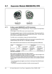
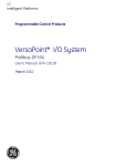
1
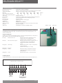
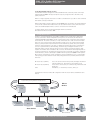
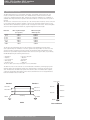
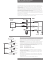
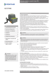
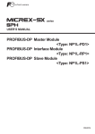
OM9 - EPI2 Profibus DPV1 interface Installation & Maintenance Instructions KEYSTONE Table of contents 1. Optional module 9: Profibus DPV1 interface 1Optional module 9: Profibus DPV1 interface 1 2 Operation and storage 1 3 Communication features 2 4EPI2 DPV1 interface 2 5 Profibus DP description 3 6 RS485 transmission mode 4 7EPI2 DPV1 power-up 5 8Data exchange during parameterization6 9 Data exchange mode8 10 Local settings16 11 GSD file17 12 Bluetooth communication module 21 13 Profibus certificate21 The OM9 Profibus DPV1 interface is an electronic module that allows you to connect the Keystone EPI2 electrical actuator to a Profibus DP network. The module has its own microprocessor and control program. It works as a pure bus interface and does not affect the actuator control integrity. It is installed inside the actuator housing and takes the electrical power from the actuator power supply module. The RS 485 interface is located on the module board. The Profibus network is fully isolated from the actuator electronics. The OM9 Profibus DPV1 is designed to support Profibus DPV0 cyclic communication and acyclic communication as per Profibus DPV1 extension. For details about EPI2 actuator the reference manual is: EPI2 Quarter-turn Electric Actuator IOM. Important For decommissioning instructions, please refer to the relevant chapter in the EPI2 manual ref. EBPRM-0091. Warning EPI2 actuator must be electrically isolated before any disassembling or reassembling operations. Before any disassembling or reassembling operations, please follow in detail the relevant paragraph of the basic installation and operating manual (latest revision available). Warning The electronic parts of the EPI2 actuators and all option modules can be damaged by a discharge of static electricity. Before you start, touch a grounded metal surface to discharge any static electricity. Warning It is assumed that the installation, configuration, commissioning, maintenance and repair works are carried out by qualified personnel and checked by responsible specialists. Warning Repair work, other than operations outlined in this manual, is strictly reserved to qualified Pentair personnel or to personnel authorized by the company itself. Note: Based on the Wiring Diagram printed on the board (I.E. DE5687R00E or DE5687R00G and subsequent), the board may have a soldered jumper or a dip switch on the Profibus Termination. Please read the manual for the relevant description. Fig. 1a: DE5687R00E Fig. 1b DE5687R00G 2. Operation and storage The module is designed to work and to be stored in the same environment as the actuator. www.pentair.com/valves Pentair reserves the right to change the contents without notice EBPRM-0093-EN-1307 OM9 - EPI2 Profibus DPV1 interface Installation & Maintenance Instructions 3. Communication features Communication protocol Profibus DP according to EN 50170 Network topology Line (bus) structure. With repeaters tree structures can also be realized Transmission medium Twisted, screened copper cable according to EN 50170 Data rate 9.6 19.2 45.45 93.75 187.5 500 1500 Kbit/sec Cable length without repeater 1200 1200 1200 1200 1000 400 200 m Approx. cable length with repeater 10 10 10 10 6 4 2 Km Station typeDPV0 and DPV1 slave Device number 32 devices per segment without repeater (max 126, with repeaters) Bus accessToken-passing between masters and polling for slaves Electrical power Actuator powered Bus termination Available on board via soldering pad Temperature-40°C, +85°C EMC protections EN 50081-2 and EN 50082-2 Types of operation Cyclic data exchange, sync mode, freeze mode, fail safe mode Baud rate Automatic recognition AddressingConfigurable via on board rotary BCD switches 4. EPI2 DPV1 interface The module consists of a single PCB that is installed inside the actuator housing. It is connected to the EPI2 base card via a flat cable. The internal wiring connects the Profibus data lines to the actuator terminal board. 4.1 On board indication Six LED’s are mounted on the EPI2 DPV1 interface to give the following indications for Field service. LED’s indications are active only when jumper JP2 is closed. DL1 (red) Internal comm. error: ON when the internal communication of the interface card is not working properly. OFF when the all communication is correct. DL2 (red) Fail safe action in progress: ON when a fail safe action is in progress due to a communication fault on the Profibus line. OFF when the Profibus communication is correct. DL3 (green) Slave ready: ON when the interface is ready to communicate to the Profibus line. OFF when the interface is not ready. DL4 (green) Reserved DL5 (green) Profibus: ON when Profibus communication has been established and the interface has entered in DATA_EX state. DL6 (green) Power: ON when the interface is correctly powered. 4.2 Wiring diagram The EPI2 DPV1 interface is connected to the actuator terminal board as shown in the figure below: Optional module - Profibus interface Connector H 5 6 7 8 9 17 18 DX-P HW Mode 19 Shield DX-N Profibus line Pentair reserves the right to change the contents without notice page 2 LED DL1 – DL6 Jumper JP2 OM9 - EPI2 Profibus DPV1 interface Installation & Maintenance Instructions 4.3 Profibus/hardwired mode selection The EPI2 DPV1 interface manages the Profibus/hardwired mode selection by means of the input indicated with HW MODE. The physical input accepts any voltage from 24 to 125 V DC or AC, polarity insensitive. When no voltage is applied, the actuator is Profibus controlled and it is possible to send commands and read the status by Profibus DP. When an appropriate voltage is applied to the HW MODE input, the actuator runs under hardwired control. In this condition the Profibus master can only read the actuator status, while the actuator follows the hardwired Open and Close controls connected to the terminal board. For further details see the relevant wiring diagram and the user manual: EPI2 Quarter-turn Electric Actuator IOM. 5. Profibus DP description Profibus is a vendor-independent, open fieldbus standard used in a wide range of applications in process automation. Vendor independence and openness are ensured by the international standards EN 50170 and EN 50254. The DP communication profile is designed for data exchange at the field level. The central controllers (i.e. PLC) communicate via a serial connection with field devices (as sensors and actuators). Data exchange is mainly cyclic. The central controller (called master) cyclically reads the input information from the field devices (called slaves) and cyclically writes the output information to the slaves. In addition the Profibus DP provides communication services for parameterization, alarm handling, and monitoring of intelligent field devices. The maximum number of master and slave devices in a bus segment is 32 without repeaters. With repeaters the number can be extended to 126 on one bus. The maximum cable length depends on the speed of transmission. The higher the speed, the shorter is the length. For instance, with baud rate 93.75 Kb/sec, the max cable length is 1,200 m without repeaters and 10,000 m with repeaters. Mono-master or multi-master system configuration can be provided. Bus access is controlled by a token passing procedure between masters and polling (master-slave procedure) between master and slaves. DP master class 1 (DPM 1): DP master class 2 (DPM 2): Slave: This is the central controller that cyclically exchanges information with the field devices. Typical devices are PLC, DCS or PC. These devices are necessary for commissioning, maintenance and diagnostics. Field device, i.e. transmitters, actuators, drives, etc. The figure below shows a Profibus DP configuration with two master devices and different slave devices. Logical token passing between master devices Master devices PC PLC General Drive Transmitter Slave devices EPI2 actuators Pentair reserves the right to change the contents without notice page 3 OM9 - EPI2 Profibus DPV1 interface Installation & Maintenance Instructions 6. RS485 transmission mode The EPI2 DPV1 interface uses a half duplex, multidrop, serial RS485 communication line. The module communicates with the masters via its RS485 interface and the transmission media consists of a shielded twisted pair cable. Transmission speed from 9.6 kbit/sec to 1.5 Mbit/sec is available. One unique transmission speed is allowed for all devices on the bus when the system is running. All devices are connected in a bus structure. Up to 32 station (master and slaves) can be connected in one segment without repeaters. Repeaters can be used to extend the number of devices up to 126 and to link the individual bus segment in order to enlarge the network area. The following table shows the relationship between baud rate, segment length and total bus length. Baud rate 9.6 K 19.2 K 45.45 K 93.75 K 187.5 K 500 K 1500 K Max. segment length Max. bus length (no repeater) with 9 repeater 1,200 m 1,200 m 1,200 m 1,200 m 1,000 m 400 m 200 m 10,000 m 10,000 m 10,000 m 10,000 m 6,000 m 4,000 m 2,000 m The bus must be terminated by an active bus terminator at the beginning and at the end of each segment. Only two terminators in one bus segment must be provided. To ensure error-free operation, both bus terminators must be powered. The maximum cable length depends on the transmission speed. Cable lengths indicated in table 2 are based on Type A cable, as specified by the EN 50170, having the following characteristics. • Impedance from 135 to 165 ohm • Capacity < 30 pF/m • Loop resistance 110 ohm/km • Wire gauge 0.64 mm • Conductor area > 0.34 mm2 The use of cable of previously used type B is not recommended. The data lines must not be reversed. Use of shielded cable is mandatory for having high system immunity against electromagnetic disturbs. The shield should be connected to ground on both sides. The data lines should be kept separate from all other cables. It should be laid in separate, conductive and earthed cable trunking. It must be ensured that there are not voltage differences between individual nodes of Profibus DP. VP (5 V DC) Device 1 Device 2 RxD/TxD-P RxD/TxD-P RxD/TxD-N 390 ohm Data line RxD/TxD-N 220 ohm Data line DGND Shielding 390 ohm DGND DGND Cable Pentair reserves the right to change the contents without notice Bus terminator page 4 OM9 - EPI2 Profibus DPV1 interface Installation & Maintenance Instructions The EPI2 DPV1 interface takes its electrical supply from the actuator power supply module. The RS485 bus transceiver is isolated from the actuator electronics. Also the voltage supply of the bus termination is isolated. The bus termination is a crucial component to ensure error-free operation: since the Profibus terminations are active circuits it is important that they remain powered also when a part of the field is powered off. Normal practice recommends to use external terminations available on the market and to power them by a separate, safe power supply. The EPI2 DPV1 interface is equipped with an on-board bus termination that can be used when the actuator is at the beginning or at the end of the bus segment. If the on-board termination is used, it is not possible to use external termination as well. The bus termination can be connected on the data lines by means of a soldering pad. The figure below shows the typical Profibus wiring. The termination must be linked to the data lines only if the actuator is at the beginning or at the end of the bus segment. Terminal board VP EPI2 DPV1 interface 390 ohm Rx/Tx-P-in Data line + Profibus RS485 transceiver Rx/Tx-P-out Soldering pad 220 ohm Rx/Tx-N-in Data line 390 ohm Rx/Tx-N-out DGND Shield Bus out 7. EPI2 DPV1 interface power-up Power on Set slave address Wait parameterization Check parameters Parameterization correct Configuration not OK Wait configuration Check configuration Configuration correct Slave fault Data exchange code Bus in Cyclic data exchange On power-up the module checks the baud rate and then waits for the ‘parameterization’ telegram from the master. The parameterization message contains user information needed for actuator operation and is listed in chapter 8: Data exchange during parameterization‘. After parameterization the module waits for the ‘configuration’ telegram from the master. The configuration message contains the number of input and output bytes reserved in the memory of the master device for each slave. Only the number of bytes determined in the configuration is transmitted between master and slave. This information is called ‘module’. The EPI2 DPV1 board implements the following modules: • Module 1 : 1 byte output; 2 bytes input • Module 2 : 4 byte output; 6 bytes input • Module 3 : 1 byte output; 2 bytes input - consistent • Module 4 : 4 byte output; 6 bytes input - consistent Consistent is an attribute that specify the capability of the module to maintains data consistency over the entire data length. In this way the data will not change during the reading by the Profibus DP-Master. For example, if module 2 is selected, the output telegram consists in 4 bytes, and the input telegram in 6 bytes. When parameters and configuration are correct, the module enters in ‘data exchange mode’ and starts with normal operation. The master cyclically sends commands to the slave and read its status. The figure on the left shows the power-up flow diagram of a DP slave. Pentair reserves the right to change the contents without notice page 5 OM9 - EPI2 Profibus DPV1 interface Installation & Maintenance Instructions 8. Data exchange during parameterization The following data is sent to the EPI2 DPV1 interface: ByteName Type 0 Reserved DPV1 1 Reserved DPV1 2 Reserved DPV1 3 Fail safe action 1 byte 4 Storage format 1 byte 5 Delay before initiating 1 byte safe operation 6 Safe position 1 byte 7 Dead band 1 byte 8 Closing direction 1 byte 9 Opening speed set 1 byte 10 Closing speed set 1 byte 11 Opening torque set 1 byte 12 Closing torque set 1 byte 13 Open limit 1 byte 14 Close limit 1 byte 15 LED color code 1 byte Range EU Default 0 1 2 3 4 0 1 0-10 Off Off Close Open Stay put Go to position LSB first MSB first sec 0-100 % 3-20 Tenth of % 0 CW 1 CCW 0 Min … … 9 Max 0 Min … … 9 Max 0 Min … … 9 Max 0 Min … … 9 Max 0 By torque 1 By position 0 By torque 1 By position 0 OP green - CL red 1 OP red - CL green LSB first MSB first 4 50 15 CW 7 7 9 9 By position By position Green LED lit in fully open position It should be noticed that every time that Profibus communication is established, the parameterization string will be sent to the device writing the parameters to the set up values. The values in parameterization string shall be modified at the Master station. Byte 0-2 Reserved for DPV1 Byte 3 Storage format This byte defines the format of the variables that are transmitted on 2 or 4 bytes. The setting of this parameter affects the format of the following data: Output data: (if module 2 is selected) Set point Input data: (if module 2 is selected) Current position General data: Slot 1 index 1 Current position Value: 0: LSB byte is transmitted first (default setting) 1: MSB byte is transmitted first Byte 4 Fail safe action This byte defines the action of the actuator in case of loss of signal. The action takes place only if the local selector is on Remote position and if the bus is operating. When the bus signal restores, also the actuator restores at its normal functioning. Value: 0: Off - disable (default setting) 1: Close 2: Open 3: Stay put 4: Go to position indicated in the parameter ‘safe position’ IMPORTANT: Fail safe action is active only if watchdog control is enabled. Pentair reserves the right to change the contents without notice page 6 OM9 - EPI2 Profibus DPV1 interface Installation & Maintenance Instructions Byte 5 Delay before initiating fail safe operation This byte defines the delay before execution of the programmed safe action Value: minimum 0 sec. maximum 10 sec. default value: 4 sec. Byte 6 Safe position This byte defines the safe position when ‘fail safe action: go to position’ is selected Value: minimum 0% maximum100% default value: 50% Byte 7 Dead band This byte defines in tenth of % the dead band of the positioning function available on the modulating actuator. The movement is inhibited until the difference between current position and requested position (position error) is lower than dead band. Value: minimum 3 = 0,3% maximum 20 = 2,0% default value: 15 = 1,5% Byte 8 Closing direction This byte defines the closing direction of the motor Value: 0: CW – clockwise (default value) 1: CCW – counter clockwise Byte 9 Opening speed set This byte defines the speed of the motor when opening Value: minimum 0 maximum9 default value: 7 Byte 10 Closing speed set This byte defines the speed of the motor when closing Value: minimum 0 maximum9 default value: 7 Byte 11 Opening torque set This byte defines the opening torque Value: minimum 0 = 40% of nominal torque maximum 9 = 100% of nominal torque default value: 9 Byte 12 Closing torque set This byte defines the closing torque Value: minimum 0 = 40% of nominal torque maximum 9 = 100% of nominal torque default value: 9 Byte 13 Open limit This byte defines the end of travel setting in open direction Value: 0: by torque 1: by position (default setting) Byte 14 Close limit This byte defines the end of travel setting in close direction Value: 0: by torque 1: by position (default setting) Byte 15 LED color code This byte defines the color of the LED indicating the fully open and fully close position as the optional local panel Value: 0: Open: LED = green; Close: LED = red (default setting) 1: Open: LED = red; Close: LED = green Pentair reserves the right to change the contents without notice page 7 OM9 - EPI2 Profibus DPV1 interface Installation & Maintenance Instructions 9. Data exchange mode The following paragraph describes the input and output messages of EPI2 DPV1 interface when working in ‘data exchange mode’ for ‘cyclic data’ and ‘acyclic data’. In all cases it is called ‘input signal’ if data is sent from actuator to bus, vice-versa it is called ‘output signal’. 9.1 Cyclic communications DPV0 9.1.1 Output data The structure of cyclic output data is as follow depending on the module selected: Module 1 or Module 3 Byteb7 b6 b5 b4 b3 b2 b1 b0 0 Reserved Reserved Reserved Reserved Reserved Stop Close Open command commandcommand Module 2 or Module 4 Byteb7 b6 b2 b5 b4 b3 b1 b0 0 ReservedReservedReservedReservedReserved Stop Close Open command commandcommand 1 ReservedReservedReservedReservedReserved Reserved Reserved Positioner enable 2 Set point 3 Set point Command Description Position Open command When this bit is set to 1 an open command is issued to the actuator. The open command is maintained for all the duration on the movement since the receiving of the bus command until the open limit has been reached. The open command is reset when a stop command is received from the bus. Associated to output data Module 1/3 or Module 2/4 Byte 0; bit 0 Close command When this bit is set to 1 a close command is issued to the actuator. The close command is maintained for all the duration on the movement since the receiving of the bus command until the close limit has been reached. The close command is reset when a stop command is received from bus. Associated to output data Module 1/3 or Module 2/4 Byte 0; bit 1 Stop command When this bit is set to 1 a stop command is issued to the actuator. The stop command received from the bus causes the reset of both open and close command. Associated to output data Module 1/3 or Module 2/4 Byte 0; bit 2 Positioner enable When this bit is set to 1 it enables the on-board positioner. The positioner is enabled as long as this bit is set to 1. Associated to Module 2/4 Byte 1; bit 0 Set point The set point received from the bus is used to produce the open or close commands to the EPI2 actuator as defined in paragraph 9.1.3: ‘Positioning algorithm’. Associated to output data Module 2/4 Byte 2 and 3 Pentair reserves the right to change the contents without notice page 8 OM9 - EPI2 Profibus DPV1 interface Installation & Maintenance Instructions 9.1.2 Input data The structure of the cyclic input data is defined depending on the module selected: Module 1 or Module 3 Byte b7b6b5b4b3b2b1 b0 0 Monitor Intermediate Motor Fully Actuator Closing Opening Fully relay position stopped closed movingopen 1 ReservedReservedReservedReservedLocal Remote Local Hardwired configurationmode Module 2 or Module 4 Byte b7b6b5b4b3b2b1 b0 0 Monitor Intermediate Motor Fully Actuator Closing Opening Fully relay position stopped closed movingopen 1 ReservedReservedReservedReservedLocal Remote Local Hardwired configurationmode 2Current position 3Current position 4 ReservedReservedReservedReservedReservedReservedReservedPositioner active 5Current torque Command Description Position Fully open The fully open indication is set to 1 when the EPI2 actuator is at fully open position. This indication reflects the status of the open limit on the EPI2 actuator. Associated to input data Module 1/3 or Module 2/4, Byte 0; bit 0 Opening The opening indication is set to 1 when the EPI2 actuator is moving towards the open direction. Associated to input data Module 1/3 or Module 2/4, Byte 0; bit 1 Closing The closing indication is set to 1 when the EPI2 actuator is moving towards the close direction. Associated to input data Module 1/3 or Module 2/4, Byte 0; bit 2 Actuator moving This indication is set to 1 when the actuator is moving either in opening or in closing direction. Associated to input data Module 1/3 or Module 2/4, Byte 0; bit 3 Fully close The fully close indication is set to 1 when the EPI2 actuator is at fully close position. This indication reflects the status of the close limit on the EPI2 actuator. Associated to input data Module 1/3 or Module 2/4, Byte 0; bit 4 Motor stopped This indication is set to 1 when the actuator is not moving and the motor has stopped. Associated to input data Module 1/3 or Module 2/4, Byte 0; bit 5 Intermediate position This indication is set to 1 when the valve is on an intermediate position. Associated to input data Module 1/3 or Module 2/4, Byte 0; bit 6 Monitor relay This indication is set to 1 when the actuator is available for bus control. Monitor relay indication means that the local selector is on remote position and no alarms are present. Associated to input data Module 1/3 or Module 2/4, Byte 0; bit 7 Hardwired mode This indication is set to 1 when the hardwired mode is selected. Associated to input data Module 1/3 or Module 2/4, Byte 1; bit 0 Local This indication is set to 1 when the optional local selector is set on local position to enable open/close local command. Associated to input data Module 1/3 or Module 2/4, Byte 1; bit 1 Remote This indication is set to 1 when the EPI2 actuator is not equipped with the optional local selector or when local selector is set on remote position to enable remote commands. Associated to input data Module 1/3 or Module 2/4, Byte 1; bit 2 Local configuration This indication is set to 1 when a local configuration in progress. Associated to input data Module 1/3 or Module 2/4, Byte 1; bit 3 Current position The current position read from the base card. Associated to input data Module 2/4, Byte 2 and 3 Positioner active This indication is set to 1 when the on-board positioner is enabled. Associated to input data Module 2/4, Byte 4; bit 0 Current torque The current torque read from the base card. Associated to input data Module 2/4, Byte 5 Pentair reserves the right to change the contents without notice page 9 OM9 - EPI2 Profibus DPV1 interface Installation & Maintenance Instructions 9.1.3 Positioning algorithm A positioning algorithm (position closed loop control) is implemented on the EPI2 DPV1 interface card. Positioning function compares the position, received from the base card, with the position request received from the bus. If the difference between ‘position request and present position’ is greater than the ‘dead band’ an open or a close command is sent to the base card. Dead band is configurable via bus from 0,3 to 2,0%. 9.1.4 Diagnostic message The EPI2 DPV1 interface manages the diagnostic indication coming from the actuator as stated by the Profibus DP V1 standard. When the EPI2 DPV1 interface needs to notify a fault to the master while in data exchange mode, it changes the function code in its response message to ‘high priority’. During the next regular bus cycle the master in turn send a ‘Slave_Diag’ request that is answered with a ‘Slave_Diag’ response. The availability of specific diagnosis information is notified by Dia.Ext_Diag flag set to 1. Once the master was able to catch the diagnosis information it returns to the standard cyclic data exchange mode. To notify the termination of the diagnosis incident the EPI2_DPV1 interface send a ‘high priority’ response. The master answers with a ‘Slave_Diag’ request that is followed by a ‘Slave_ Diag’ response with Dia.Ext_Diag flag set to 0. MasterEPI2_DPV1 Data exchange request Data exchange response Data exchange request Data exchange responde (Function code = high priority) Slave_Diag request Salve-Diag response (Diag Ext-Diag = 1) Data exchange request Data exchange response Data exchange request Data exchange response (Function code = high priority) Slave_Diag request Slave_Diag response (Diag.Ext_Diag = 0) Data exchange request Data exchange response The diagnostic message implemented by EPI2_DPV1 has the following structure: MSLSB Octet 1 Octet 2 Octet 3 Octet 4 Octet 5 Octet 6 Type IRD, length 0 0 0 0 a a a a Type DRD, Lenght Identifier, Status_Type Slot_Number Status_Specifier d d d d d d d d d d d d d d d d Standard diagnostic block 6 octets Identifier related diagnostic block 2 Octets Device related diagnostic block Status messages 6 octets Pentair reserves the right to change the contents without notice page 10 Fault on Fault off OM9 - EPI2 Profibus DPV1 interface Installation & Maintenance Instructions Standard diagnostic block Octet 1 Bit0 Diag_Station_Non_Existent Diag_Station_Not_Ready Diag_Cfg_Fault Diag_Ext_Diag Diag_Not_Supported Diag_Invalid_Slave_Response Diag.Prm_Fault Diag.Master_Lock Octet 2 (1) = Slave does not exist (sets master) (1) = Slave not ready for data exchange (1) = Slave has mismatching configuration data (0) = Slave sends standard diagnosis data only (6 bytes) or with extended diagnosis without fault (i.e. when the fault condition disappears) (1) = Slave does not support the required function (0) = Set by slave (1) = Set by master in case of fault (1) = Incorrect parameterization (1) = Slave has been parameterized by a different master (sets master) Bit0 Diag.Pm_Req (1) = Slave has to be re-parameterized Diag.Stat_Diag (1) = During start-up phase slave not able to provide valid diagnosis data DP (1) = Fixed at 1 Diag.WD_On (1) = Threshold monitoring activated Diag.Freeze_Mode (1) = FREEZE command received Diag.Sync_Mode (1) = SYNC command received reserved Diag.Deactivated (1) = Diagnosis deactivated (sets master) Octet 3 Bit0 reserved Diag.Ext_Diag_Overflow (1) = Slave has more diagnosis data than fit into the buffer Octet 4 Bit0 Diag_Master_Add ddress of the master that has parameterized the slave 0xFF A when slave not parameterized yet Octet 5 Bit0 Ident_Number High byte of the slave’s ident number. EPI2_DPV1 report 0x09 Octet 6 Bit0 Ident_Number Low byte of the slave’s ident number, EPI2_DPV1 report 0xE3 Pentair reserves the right to change the contents without notice page 11 OM9 - EPI2 Profibus DPV1 interface Installation & Maintenance Instructions Identifier related diagnosis block Octet 7 Bit0 01Header: EPI2_DPV1 report 0x42 Low byte of the slave’s ident number, EPI2_DPV1 report 0xE3 Block_Lenght Selection Number of octets of this block including this header (01) = Identifier Related Diagnostic Octet 8 Bit0 0000Identifier_Diagnosis_Data_Array Identifier_Diagnosis_Entry_1(0) = Module 1 has no diagnosis data (1) = Module 1 has diagnosis data Identifier_Diagnosis_Entry_2(0) = Module 2 has no diagnosis data (1) = Module 2 has diagnosis data Identifier_Diagnosis_Entry_3(0) = Module 3 has no diagnosis data (1) = Module 3 has diagnosis data Identifier_Diagnosis_Entry_4(0) = Module 4 has no diagnosis data (1) = Module 4 has diagnosis data Padding bits Octet 9 Bit0 0 0Header: EPI2_DPV1 report 0x06 Block_Lenght Selection Octet 10 Number of octets of this block including this header (00) = Device Related Diagnostic Bit0 10000001Status: EPI2_DPV1 report 0x81 Status_Type Identifier Octet 11 (1) = Status_Message (1) = Status Bit0 00000000Slot_Number: EPI2_DPV1 report 0x00 Octet 12 Bit0 00000000Status_Specifier: EPI2_DPV1 report 0x00 Pentair reserves the right to change the contents without notice page 12 OM9 - EPI2 Profibus DPV1 interface Installation & Maintenance Instructions Octet 13 Bit0 Status_Data_Description Octet 14 (1) = Not Operative in Open Direction (1) = Not Operative in Close Direction (1) = Power Fail Alarm (1) = HI-HI Torque in Opening (1) = HI-HI Torque in Closing (1) = Stroke Limit Alarm (1) = Alarm on Optional Control Card (Pushbutton) (1) = Motor direction Alarm Bit0 Status_Data_Description (1) = Jammed valve (1) = Hardware error (1) = Position Sensor Failure (1) = HI-HI Temperature (1) = Local Configuration in Progress (1) = Reserved (1) = Reserved (1) = Reserved The meaning of every diagnosis event listed in the extended diagnostic block is documented in the GSD file where to each bit corresponds a specific text to describe the device related diagnosis. A full Profibus DP compliant master should be able to show the correspondent text in the event of a diagnostic message. □ Not Operative in Open direction This bit is set when the open commands are not available due to current alarm trip in open direction. The diagnostic indication is cleared when the alarm that has generated the fault disappears. □ Not Operative in Close direction This bit is set when the close commands are not available due to current alarm trip in close direction. The diagnostic indication is cleared when the alarm that has generated the fault disappears. □ Power Failure Alarm This bit is set when the main supply is not in the proper range. The diagnostic indication is cleared at the next power up if the power supply is corrected. □ HI-HI Torque in Opening This bit is set when the torque has reached the programmed limit while the actuator was moving in opening direction. The diagnostic indication is cleared by a close command. □ HI-HI Torque in Closing This bit is set when the torque has reached the programmed limit while the actuator was moving in closing direction. The diagnostic indication is cleared by an open command. □ Stroke Limit Alarm This bit is set when the current position is behind the open or close limit switches or as result of an incorrect torque set.. The diagnostic indication is cleared when the position returns within the limits or after a successful torque configuration procedure. □ Alarm on Optional Local Control (Pushbutton) This bit is set when the optional local control does not work correctly. The diagnostic indication is cleared when the local control works without problems. □ Motor Direction Alarm This bit is set when the motor drive has recognised an incorrect behaviour. The diagnostic indication is cleared by a command in the opposite direction. □ Jammed Valve This bit is set when the actuator detects a jammed valve condition. The diagnostic indication is cleared by a command in the opposite direction. □ Hardware Error This bit is set when the actuator detects a general hardware error. The diagnostic indication is cleared at the next power up under normal condition. □ Position Sensor Failure This bit is set when the actuator detects that executing a command the position sensor is not working properly. The diagnostic indication is cleared by a command in the opposite direction. □ HI-HI Temperature This bit is set when the internal temperature is out from the operational limits. The diagnostic indication is cleared when the internal is within the limits. □ Local Configuration in Progress This bit is set when the actuator detects that a local operator is executing a local configuration. The diagnostic indication is cleared when the local operator finishes the configuration and the actuator returns to normal operations. Pentair reserves the right to change the contents without notice page 13 OM9 - EPI2 Profibus DPV1 interface Installation & Maintenance Instructions 9.2Acyclic communication DPV1 This paragraph defines the composition of the acyclic communication defined as per Profibus DPV1 standard. The data available on acyclic communication is organized as shown in the following table: SlotIndex length Slot 0: Name plate data 0 0 12 bytes 0 1 12 bytes 0 2 12 bytes 0 3 28 bytes Access Description Read only Read only Read only Read only Actuator serial number Actuator type Valve tag name Profibus interface Slot 1: General data 1 0 3 bytes Read only 1 1 3 bytes Read only 1 2 1 byte Read only General data about current working condition Position and torque temperature Slot 2: Actuator configuration data 2 0 4 bytes Read and write 2 1 1 byte Read and write 2 2 6 bytes Read only 2 3 3 bytes Read only Torque and speed set Dead band General configuration Fail safe 9.2.1 Name plate ByteName Dim Range EU Slot 0, Index 0, length 12 bytes - Only read: Actuator serial number 0-11 Actuator serial number 12 bytes String Slot 0, Index 1, length 12 bytes - Only read: Actuator type 0-11 Actuator type 12 bytes String Slot 0, Index 2, length 12 bytes - Only read: Valve tag name 0-11 Valve tag 12 bytes String Slot 0, 0-19 20-23 24-27 String String String Index 3, length 28 bytes - Only read: Profibus interface Model name 20 bytes Firmware revision 4 bytes Hardware revision 4 bytes 9.2.2 General data Slot 1, Index 0, length 3 bytes - Read only: General data about current working condition ByteName bit Description 0 Byte 0 1 Byte 1 2 Byte 2 0 Fully open position 1Opening 2Closing 3 Actuator moving 4 Fully close 5 Motor stopped 6 Intermediate position 7 Monitor relay 0 Hardwired mode 1 Local control 2 Remote control 3 Local configuration 4 5 6 7 0 Positioner active 1 2 3 4 5 6 7 Pentair reserves the right to change the contents without notice page 14 OM9 - EPI2 Profibus DPV1 interface Installation & Maintenance Instructions ByteName Dim Range EU Slot 1, Index 1, length 3 bytes - Only read: Position and torque 0-1 Current position 2 bytes 0 - 1000 2 Current torque 1 byte 0 - 100 0,1% % Slot 1, Index 2, length 1 byte - Only read: Temperature 0 Internal temperature 1 byte °C -128 +127 9.2.3 Actuator configuration Byte Name Dim RangeEU Slot 2, Index 0, length 4 bytes – Read and write: Torque and speed set 0 Opening speed set 1 byte 0 Min …… 9Max 1 Closing speed set 1 byte 0 Min …… 9Max 2 Opening torque set 1 byte 0 Min …… 9Max 3 Closing torque set 1 byte 0 Min …… 9Max Slot 2, Index 1, length 1 byte – Read and write: Dead band 0 Dead band 1 byte 3-20 Tenth of % Slot 2, Index 2, length 6 bytes – Only read: General configuration 0 Storage format 1 byte 0 LSB first 1 1 MSB first 1 Closing direction 1 byte 0 CW 1 CCW 2 Open limit 1 byte 0 By torque 1 By position 3 Close limit 1 byte 0 By torque 1 By position 4 Nominal torque 1 byte 0 63 Nm 1 125 Nm 2 250 Nm 3 500 Nm 4 1000 Nm 5 2000 Nm 5 LED color code 1 byte 0 OP green - CL red 1 OP red - CL green Byte Name Dim Slot 2, Index 3, length 3 bytes - Read only: Fail safe 0 Fail safe action 1 byte 1 Delay before initiating safe oper. 1 byte 2 Safe position 1 byte Pentair reserves the right to change the contents without notice RangeEU 0 Off 1 Open 2Close 3 Stay put 4 Go to position 0-10 sec 0-100 % page 15 OM9 - EPI2 Profibus DPV1 interface Installation & Maintenance Instructions 10. Local settings The EPI2 DPV1 board is equipped with a set of switches to allow the operator to configure the Profibus address. Furthermore two soldering pads are available to connect the Profibus termination circuit to be used in case that the external termination is not available. To perform the local setting on the EPI2 DPV1 board, it is necessary to follow carefully the procedures explained in the EPI2 quarter-turn electric actuator IOM at chapter 6: ‘Actuator settings and configuration’. 10.1 Profibus address setting Profibus address is configured by means of the switches indicated in the figure and located on the EPI2 DPV1 interface soldering side, direct accessible when the control unit cover is removed. To enter a new Profibus address the EPI2 actuator needs to be powered. Fig. 2 Configuration procedure: • Move the dip switch ENA-CFG to the ON position: the CFG_ON LED is turned ON to indicate that the actuator is entered in configuration mode • Set the new Profibus address on the rotary switches UNIT and DEC and on the dip switch HUNDR. E.g. address 028 corresponds to: - HUNDR. on OFF position - DEC. on position 2 - UNIT on position 8 • Press the push button ENTER to confirm the new settings: if the new address is correct the ACQ_CFG LED is turned ON • Move the dip switch CFG_ENA to the OFF position to exit from configuration mode: the CFG_ON LED is turned OFF and the OM9 Profibus DPV1 restarts with the new address. It is not required to power down and start up the actuator. 10.2.a Profibus termination on board code DE5687R00E On board termination is located on the side of the EPI2 DPV1 module as shown in the photo below. The termination is activated by two soldering paths indicated with JP12 and JP13: On default the soldering paths are left open and the termination is not active. Pentair reserves the right to change the contents without notice page 16 To activate the on board termination both the soldering paths must be closed as indicated. OM9 - EPI2 Profibus DPV1 interface Installation & Maintenance Instructions 10.2.b Profibus termination on board code DE5687R00G and subsequent On board termination is done through the dip switch located on the board as shown in the photo below. The termination is activated when the dip switches are in position ON. To remove the termination, please move both the switches to 1. 11. GSD file ; GSD-File for F02 EPI2 Biffi Italia srl ; Author: C.Doglio ; Date: 20.07.05 ; File: F02_09E3.GSD rev.0.0 ;============================================= ============== ; #Profibus_DP ; ; Prm-Text-Def-List: ; ;Text definition 1 PrmText=1 Text(0)=’LSB first’ Text(1)=’MSB first’ EndPrmText ; ;Text definition 2 PrmText=2 Text(0)=’Off’ Text(1)=’Close’ Text(2)=’Open’ Text(3)=’Stayput’ Text(4)=’Go to position’ EndPrmText ; ;Text definition 4 PrmText=4 Text(0)=’By Torque’ Text(1)=’By Position’ EndPrmText ; ;Text definition 5 PrmText=5 Text(0)=’GREEN lit when OPEN’ Text(1)=’RED lit when OPEN ‘ EndPrmText ;Text definition 6 PrmText=6 Text(0)=’CW’ Text(1)=’CCW’ EndPrmText Pentair reserves the right to change the contents without notice page 17 OM9 - EPI2 Profibus DPV1 interface Installation & Maintenance Instructions ; ; Ext-User-Prm-Data-Def-List: ; ExtUserPrmData=1 ‘Storage Format’ Unsigned8 0 0-1 Prm_Text_Ref=1 EndExtUserPrmData ExtUserPrmData=2 ‘Fail safe action’ Unsigned8 0 0-4 Prm_Text_Ref=2 EndExtUserPrmData ExtUserPrmData=3 ‘Fail safe delay’ Unsigned8 4 0-10 EndExtUserPrmData ExtUserPrmData=4 ‘Safe position’ Unsigned8 50 0-100 EndExtUserPrmData ExtUserPrmData=5 ‘Closing direction’ Unsigned8 0 0-1 Prm_Text_Ref=6 EndExtUserPrmData ExtUserPrmData=6 ‘Opening speed set’ Unsigned8 7 0-9 EndExtUserPrmData ExtUserPrmData=7 ‘Closing speed set’ Unsigned8 7 0-9 EndExtUserPrmData ExtUserPrmData=8 ‘Opening Torque set’ Unsigned8 9 0-9 EndExtUserPrmData ExtUserPrmData=9 ‘Closing Torque set’ Unsigned8 9 0-9 EndExtUserPrmData ExtUserPrmData=10 ‘Open limit’ Unsigned8 1 0-1 Prm_Text_Ref=4 EndExtUserPrmData ExtUserPrmData=11 ‘Close limit’ Unsigned8 1 0-1 Prm_Text_Ref=4 EndExtUserPrmData ExtUserPrmData=12 ‘Dead band’ Unsigned8 15 3-20 EndExtUserPrmData ExtUserPrmData=13 ‘LED color code’ Unsigned8 0 0-1 Prm_Text_Ref=5 EndExtUserPrmData ; ; Unit definition list: ; GSD_Revision=4 ; Vendor_Name=’Biffi Italia srl’ Model_Name=’F02 EPI2 DPV1’ Revision=’Release 0.0’ Ident_Number=0x09E3 Protocol_Ident=0 Station_Type=0 Hardware_Release=’Hardware Release DE5687 rev.0.0’ Software_Release=’Software Release SW=0.00’ ; 9.6_supp=1 19.2_supp=1 45.45_supp=1 93.75_supp=1 187.5_supp=1 500_supp=1 1.5M_supp=1 Pentair reserves the right to change the contents without notice page 18 OM9 - EPI2 Profibus DPV1 interface Installation & Maintenance Instructions MaxTsdr_9.6=60 MaxTsdr_19.2=60 MaxTsdr_45.45=60 MaxTsdr_93.75=60 MaxTsdr_187.5=60 MaxTsdr_500=100 MaxTsdr_1.5M=150 ; Implementation_Type=’SPC3’ Bitmap_Device=’F02k_R’ Bitmap_Diag=’F02k _D’ Bitmap_SF=’F02 _C’ ; ; Slave-Specification: ; Freeze_Mode_supp=1 Sync_Mode_supp=1 Auto_Baud_supp=1 Set_Slave_Add_supp=0 Min_Slave_Intervall=1 Max_Diag_Data_Len=16 Slave_Family=0 Fail_Safe=1 ; ; UserPrmData: Length and Preset: ; User_Prm_Data_Len=16 User_Prm_Data=0x00,0x00,0x00,\ 0x00, \ 0x00, \ 0x04, \ 0x32, \ 0x0f, \ 0x00, \ 0x07, \ 0x07, \ 0x09, \ 0x09, \ 0x01, \ 0x01, \ 0x00 ; Max_User_Prm_Data_Len=16 ; Ext_User_Prm_Data_Const(0)=0 Ext_User_Prm_Data_Const(1)=0 Ext_User_Prm_Data_Const(2)=0 Ext_User_Prm_Data_Ref(3)=1 Ext_User_Prm_Data_Ref(4)=2 Ext_User_Prm_Data_Ref(5)=3 Ext_User_Prm_Data_Ref(6)=4 Ext_User_Prm_Data_Ref(7)=12 Ext_User_Prm_Data_Ref(8)=5 Ext_User_Prm_Data_Ref(9)=6 Ext_User_Prm_Data_Ref(10)=7 Ext_User_Prm_Data_Ref(11)=8 Ext_User_Prm_Data_Ref(12)=9 Ext_User_Prm_Data_Ref(13)=10 Ext_User_Prm_Data_Ref(14)=11 Ext_User_Prm_Data_Ref(15)=13 ; ; Modular_Station=1 Max_Module=1 Max_Input_Len=6 Max_Output_Len=4 Max_Data_Len=10 ;0-2 Reserved DPV1 ;3- Storage Format ;4 -Fail Safe action ;5 -Delay before Fail Safe ;6 -Safe position ;7 -Dead band ;8 -Closing direction ;9 -Opening speed set ;10 -Closing speed set ;11-Opening Torque set ;12-Closing Torque set ;13-Open limit ;14-Close limit ;15-LED color code Pentair reserves the right to change the contents without notice page 19 OM9 - EPI2 Profibus DPV1 interface Installation & Maintenance Instructions ; ; Slave-Specification: ; DPV1_Slave=1 ; C1_Read_Write_supp=0 C2_Read_Write_supp=1 C2_Max_Data_Len=240 C2_Response_Timeout=100 C2_Read_Write_required=0 C2_Max_Count_Channels=3 Max_Initiate_PDU_Length=72 Diagnostic_Alarm_supp=0 Process_Alarm_supp=0 Pull_Plug_Alarm_supp=0 Status_Alarm_supp=0 Update_Alarm_supp=0 Manufacturer_Specific_Alarm_supp=0 Extra_Alarm_SAP_supp=0 Alarm_Sequence_Mode_Count=0 Alarm_Type_Mode_supp=0 Diagnostic_Alarm_required=0 Process_Alarm_required=0 Pull_Plug_Alarm_required=0 Status_Alarm_required=0 Update_Alarm_required=0 Manufacturer_Specific_Alarm_required=0 DPV1_Data_Types=0 WD_Base_1ms_supp=1 Check_Cfg_Mode=0 ; ;Device related Diagnosis ; Unit_Diag_Bit(24)=’Not Operative Open’ Unit_Diag_Bit(25)=’Not Operative Close’ Unit_Diag_Bit(26)=’Power Fail Alarm’ Unit_Diag_Bit(27)=’HI-HI Torque in Opening’ Unit_Diag_Bit(28)=’HI-HI Torque in Closing’ Unit_Diag_Bit(29)=’Stroke Limit Alarm’ Unit_Diag_Bit(30)=’Local Control Alarm’ Unit_Diag_Bit(31)=’Motor Direction Alarm’ Unit_Diag_Bit(32)=’Jammed Valve’ Unit_Diag_Bit(33)=’Hardware Error’ Unit_Diag_Bit(34)=’Postition Sensor Failure’ Unit_Diag_Bit(35)=’HI-HI Temperature’ Unit_Diag_Bit(36)=’Local Configuration in progress’ ; ; Module Definition List ; Module=’Mod.1: 2 B.In, 1 B.Out’ 0x11,0x20 1 EndModule Module=’Mod.2: 6 B.In, 4 B.Out’ 0x15,0x23 2 EndModule Module=’Mod.3: 2 B.In, 1 B.Out - Cons.’ 0x91,0x20 3 EndModule Module=’Mod.4: 6 B.In, 4 B.Out - Cons.’ 0x95,0xa3 4 EndModule Pentair reserves the right to change the contents without notice page 20 OM9 - EPI2 Profibus DPV1 interface Installation & Maintenance Instructions 12. Bluetooth communication module The OM9 module is provided with integrated Bluetooth module. In www.biffi.it you can download A-Manager program to modify each settings by integrated Bluetooth module. After installation of A-Manager program, please clic on ‘Operations’button and then clic on ‘Bluetooth Control’button and tick ‘on’. The features and functionalities performed with Bluetooth module are indicated in A-Manager IOM for PDA (BIFCS-0029) and PC (BIFCS-0028). 13. Profibus certificate Pentair reserves the right to change the contents without notice page 21