1
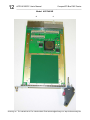
ACPC4610E/CC
CompactPCI Bus Non-Intelligent PMC Carrier
Board
USER’S MANUAL
ACROMAG INCORPORATED
30765 South Wixom Road
P.O. BOX 437
Wixom, MI 48393-7037 U.S.A.
[email protected]
Copyright 2008, Acromag, Inc., Printed in the USA.
Data and specifications are subject to change without notice.
Tel: (248) 295-0310
Fax: (248) 624-9234
8500-819-C09J010
2
ACPC4610E/CC User’s Manual
CompactPCI Bus PMC Carrier
__________________________________________________________________
TABLE OF
CONTENTS
IMPORTANT SAFETY CONSIDERATIONS
You must consider the possible negative effects of power, wiring,
component, sensor, or software failure in the design of any type of
control or monitoring system. This is very important where property
loss or human life is involved. It is important that you perform
satisfactory overall system design and it is agreed between you and
Acromag, that this is your responsibility.
1.0
The information of this manual
may change without notice.
Acromag makes no warranty
of any kind with regard to this
material, including, but not
limited to, the implied
warranties of merchantability
and fitness for a particular
purpose. Further, Acromag
assumes no responsibility for
any errors that may appear in
this manual and makes no
commitment to update, or
keep current, the information
contained in this manual. No
part of this manual may be
copied or reproduced in any
form without the prior written
consent of Acromag, Inc.
General Information
KEY FEATURES…………...… …… …. … …… … …. .
SIGNAL INTERFACE PRODUCTS……………………
3
3
2.0 PREPARATION FOR USE
UNPACKING AND INSPECTION...…………………...
CARD CAGE CONSIDERATIONS.........……………..
Non-Isolation Considerations...........................
Rear I/O Connector……………….………………
CompactPCI Bus Connector.…………………...
4
4
4
5
6
3.0 SERVICE AND REPAIR
SERVICE AND REPAIR ASSISTANCE...……….…...
PRELIMINARY SERVICE PROCEDURE...…………..
WHERE TO GET HELP…………………………………
7
7
7
4.0 SPECIFICATIONS
PHYSICAL..................................................................
CONNECTORS…………………………………………..
ENVIRONMENTAL....…….……………………………..
POWER REQUIREMENTS...…………………………..
CompactPCI BUS COMPLIANCE…………………….
RELIABILITY PREDICTION.......................................
8
8
8
9
9
9
APPENDIX
MODEL TRANS-C4610…………………………………
MODEL 5028-432……………………………………….
MODEL 5025-288……………………………………….
10
10
11
DRAWINGS
MODEL ACPC4610E…………..……………………….
MODEL ACPC4610CC.………..……………………….
4502-096 ACPC4610 BLOCK DIAGRAM……………
MODEL TRANS-C4610…………………………………
4502-089 TRANS-C4610 SCHEMATIC………………
4501-919 MODEL 5028-432……………………………
4501-920 MODEL 5025-288……………………………
Certificate of Volatility…………………………………
Trademarks are the property of their respective owners.
12
13
14
15
16
17
18
19
__________________________________________________________________________
Acromag, Inc. Tel: 248-295-0310 Fax: 248-624-9234 Email:[email protected] http://www.acromag.com
ACPC4610E/CC User’s Manual
CompactPCI Bus PMC Carrier
___________________________________________________________________
The ACPC4610E/CC is a 3U CompactPCI Bus Non-Intelligent PMC
carrier board designed for the 32-bit 33MHz or 66MHz CompactPCI bus.
R
The carrier card uses a PLX Technology Bridge Chip (PCI6540) to interface
between the CompactPCI bus and one PMC mezzanine I/O module card.
Model ACPC4610E is an air-cooled extended temperature product which
can be used for front and rear PMC mezzanine I/O modules. Front I/O can
be accessed through the front panel. Rear I/O can be accessed though the
J2 connector on the carrier.
•
•
•
ESD Strip on ACPC4610E Board - The ACPC4610E board has been
designed to provide electrostatic discharge (ESD) capability by using an
ESD strip on the board per IEEE1101.10.
Injector/Ejector Handle - The ACPC4610E uses a modern
injector/ejector handle, which pushes the board into the rack during
installation and has a positive self-locking mechanism so it cannot be
unlocked accidentally. This handle is fully IEEE 1101.10 compliant and
is needed to give leverage to install and remove the board.
EMC Front Panel - The ACPC4610E uses the preferred EMC front
panel per IEEE 1101.10 specification.
3
1.0 GENERAL
INFORMATION
MODEL ACPC4610E
KEY FEATURES
Model ACPC4610CC is a conduction cooled product which is usually
only used for rear Conduction Cooled PMC mezzanine I/O modules. Rear
I/O can be accessed though the J2 connector on the carrier.
MODEL ACPC4610CC
•
KEY FEATURES
Conduction Cooled Frame - The ACPC4610CC board has a custom
conduction cooled assembly consisting of a conduction cooled frame,
R
thermo bars, ejector/injectors and Wedge-Loks designed to thermally
conduct heat away from the Conduction Cooled PMC modules per
ANSI/VITA 30.1-2001.
Model TRANS-C4610 Transition Module: This module plugs into the
rear backplane directly behind the ACPC4610E carrier board. The field I/O
connections are made through the backplane to the J2 connector of the
carrier board and then routed to a 68 pin SCSI-3 connector P1, on the
transition module, for rear exit from the card cage. This module is available
for use in card cages which provide rear exit for I/O connections via 80 mm
wide transition modules (transition modules can only be used in card cages
specifically designed for them). It is a single-height (3U), single-slot module
and adheres to the CompactPCI mechanical dimensions and IEEE Standard
(1101.11-1998), with a printed circuit board depth of 80mm, which is a
standard transition module depth. The transition module connects to
Acromag Termination Panel (Model 5025-288) using a round 68 conductor
shielded cable (Model 5028-432) to the rear of the card cage, and to the
ACPC4610E board within the card cage.
SIGNAL INTERFACE
PRODUCTS
CompactPCI Transition
Module
Model 5028-432: A 2-meter cable, with a male SCSI-3 connector at both
ends and 34 twisted pairs. This cable is used for connecting the TRANSC4610 board to Model 5025-288 termination panels.
Cables
Model 5025-288: DIN-rail mountable panel provides 68 screw terminals
for universal field I/O termination. Connects to the TRANS-C4610 board,
via SCSI-3 to twisted pair cable, Model 5028-432.
Termination Panel
__________________________________________________________________________
Acromag, Inc. Tel: 248-295-0310 Fax: 248-624-9234 Email:[email protected] http://www.acromag.com
4
ACPC4610E/CC User’s Manual
CompactPCI Bus PMC Carrier
__________________________________________________________________
2.0 PREPARATION
FOR USE
UNPACKING AND
INSPECTION
Upon receipt of this product, inspect the shipping carton for evidence of
mishandling during transit. If the shipping carton is badly damaged or
water stained, request that the carrier's agent be present when the carton
is opened. If the carrier's agent is absent when the carton is opened and
the contents of the carton are damaged, keep the carton and packing
material for the agent's inspection.
For repairs to a product damaged in shipment, refer to the Acromag
Service Policy to obtain return instructions. It is suggested that salvageable
shipping cartons and packing material be saved for future use in the event
the product must be shipped.
WARNING: This board
utilizes static sensitive
components and should
only be handled at a staticsafe workstation.
CARD CAGE
CONSIDERATIONS
IMPORTANT: Adequate air
circulation must be
provided to prevent a
temperature rise above the
maximum operating
temperature.
Non-Isolation
Considerations
This board is physically protected with packing material and electrically
protected with an anti-static bag during shipment. However, it is
recommended that the board be visually inspected for evidence of
mishandling prior to applying power.
Refer to the specifications for loading and power requirements. Be sure
that the system power supplies are able to accommodate the power
requirements of the system boards, plus the installed Acromag board, within
the voltage tolerances specified.
In an air cooled assembly, adequate air circulation must be provided to
prevent a temperature rise above the maximum operating temperature and
to prolong the life of the electronics. If the installation is in an industrial
environment and the board is exposed to environmental air, careful
consideration should be given to air-filtering.
In a conduction cooled assembly, adequate thermo conduction must be
provided to prevent a temperature rise above the maximum operating
temperature.
The board is non-isolated, since there is electrical continuity between the
CompactPCI bus and PMC module grounds. As such, the field I/O
connections are not isolated from the system. Care should be taken in
designing installations without isolation to avoid noise pickup and ground
loops caused by multiple ground connections.
__________________________________________________________________________
Acromag, Inc. Tel: 248-295-0310 Fax: 248-624-9234 Email:[email protected] http://www.acromag.com
ACPC4610E/CC User’s Manual
CompactPCI Bus PMC Carrier
___________________________________________________________________
The model ACPC4610E/CC carrier field I/O connections are made through
the rear via J2 for a single PMC mezzanine I/O module card.
5
Rear I/O Connector
Table 2.1 indicates the pin assignments for the CompactPCI I/O signal
mapping at the J2 connector. The connector consists of 22 rows of six pins
labeled A, B, C, D, E and F. Pin A1 is located near the center of the board,
viewed from the front component side. J2 is used to route a single PMC
Module’s field signals from the carrier to the backplane.
IMPORTANT: Model ACPC4610E/CC cannot be used in 64 bit cPCI or PXI
systems as rear I/O (J2) is mapped to the same connector as the additional
control lines for 64-bit cPCI or PXI.
Pin
Row A
Row B
Row C
Row D
Row E
1
VI/O
64
63
62
61
2
60
59
58
57
56
3
55
54
53
52
51
4
50
49
48
47
46
5
45
44
43
42
41
6
40
39
38
37
36
7
35
34
33
32
31
8
30
29
28
27
26
9
25
24
23
22
21
10
20
19
18
17
16
11
15
14
13
12
11
12
10
9
8
7
6
13
5
4
3
2
1
14
+3.3V
+3.3V
+3.3V
+5V
+5V
NC
NC
NC
NC
15
NC
NC
NC
NC
NC
NC
16
NC
NC
NC
NC
NC
17
NC
NC
NC
NC
NC
18
NC
NC
NC
NC
NC
19
NC
NC
NC
NC
NC
20
NC
NC
NC
NC
NC
21
NC
NC
NC
NC
NC
22
Notes:
1. Entries in the table are of the PMC J14 pin number.
2. NC is no connections, NOT USED by this carrier board.
3. VI/O NOT USED by this carrier board.
Row F
GND
GND
GND
GND
GND
GND
GND
GND
GND
GND
GND
GND
GND
GND
GND
GND
GND
GND
GND
GND
GND
GND
Table 2.1: CompactPCI I/O
Signals J2 Connections
__________________________________________________________________________
Acromag, Inc. Tel: 248-295-0310 Fax: 248-624-9234 Email:[email protected] http://www.acromag.com
6
ACPC4610E/CC User’s Manual
CompactPCI Bus PMC Carrier
__________________________________________________________________
CompactPCI Bus
Connectors for J1
Table 2.2 indicates the pin assignments for the 32-bit CompactPCI bus
signals at the J1 connector. The connector consists of 25 rows of six pins
labeled A, B, C, D, E and F. Pin A1 is located at the lower right hand corner
of the connector if the board is viewed from the front component side.
Refer to the CompactPCI bus specification for additional information on
the CompactPCI bus signals.
Table 2.2: CompactPCI
Bus J1 Connections
Pin
Row A
Row B
Row C
Row D
Row E
Row F
1
+5V
-12v
TRST#
+12V
+5V
GND
2
TCK
+5V
TMS
TDO
TDI
GND
3
INTA#
INTB#
INTC#
+5V
INTD#
GND
4
IPM*PWR HEAL*#
V(I/0)
INTP
INTS
GND
5
BR*A5
BR*B5
RST#
GND
GNT#
GND
6
REQ#
GND
+3.3V
CLK
AD[31]
GND
7
AD[30]
AD[29]
AD[28]
GND
AD[27]
GND
8
AD[26]
GND
V(I/O)
AD[25]
AD[24]
GND
9
C/BE[3]#
IDSEL
AD[23]
GND
AD[22]
GND
10
AD[21]
GND
+3.3V
AD[20]
AD[19]
GND
11
AD[18]
AD[17]
AD[16]
GND
C/BE[2]#
GND
12
GND
13
KEY
AREA
GND
14
GND
15
+3.3V
FRAM#
IRDY#
BD SEL#
TRDY#
GND
16 DEVSEL#
GND
V(I/O)
STOP#
LOCK#
GND
17
+3.3V
IP*SCL
IPM*DA
GND
PERR#
GND
18
SERR#
GND
+3.3V
PAR
C/BE[1]#
GND
19
+3.3V
AD[15]
AD[14]
GND
AD[13]
GND
20
AD[12]
GND
V(I/O)
AD[11]
AD[10]
GND
21
+3.3V
AD[9]
AD[8]
M66EN
C/BE[0]#
GND
22
AD[7]
GND
+3.3V
AD[6]
AD[5]
GND
23
+3.3V
AD[4]
AD[3]
+5V
AD[2]
GND
24
AD[1]
+5V
V(I/O)
AD[0]
ACK64#
GND
25
+5V
REQ64#
ENUM#
+3.3V
+5V
GND
Notes:
1. Pound (#) is used to indicate an active-low signal.
2. BOLD ITALIC Logic Lines are NOT USED by this carrier board.
__________________________________________________________________________
Acromag, Inc. Tel: 248-295-0310 Fax: 248-624-9234 Email:[email protected] http://www.acromag.com
ACPC4610E/CC User’s Manual
CompactPCI Bus PMC Carrier
___________________________________________________________________
Surface-Mounted Technology (SMT) boards are generally difficult to
repair. It is highly recommended that a non-functioning board be returned to
Acromag for repair. The board can be easily damaged unless special SMT
repair and service tools are used. Further, Acromag has automated test
equipment that thoroughly checks the performance of each board. When a
board is first produced and when any repair is made, it is tested, placed in a
burn-in room at elevated temperature, and retested before shipment.
7
3.0 SERVICE AND
REPAIR
SERVICE AND REPAIR
ASSISTANCE
PRELIMINARY SERVICE
PROCEDURE
Please refer to Acromag's Service Policy Bulletin or contact Acromag for
complete details on how to obtain parts and repair.
Before beginning repair, be sure that all of the procedures in Section 2,
Preparation For Use, have been followed. Also, refer to the documentation
of your PMC module to verify that it is correctly configured. Replacement of
the board with one that is known to work correctly is a good technique to
isolate a faulty board.
CAUTION: POWER MUST
BE TURNED OFF
BEFORE REMOVING OR
INSERTING BOARDS
If you continue to have problems, your next step should be to visit the
Acromag worldwide web site at http://www.acromag.com. Our web site
contains the most up-to-date product and software information.
WHERE TO GET HELP
Choose the “Support” hyperlink in our website’s top navigation row then
select “Embedded Board Products Support” or go to
http://www.acromag.com/subb_support.cfm to access:
• Application Notes
• Frequently Asked Questions (FAQ’s)
• Knowledge Base
• Tutorials
• Software Updates/Drivers
www.acromag.com
An email question can be submitted from within the Knowledge Base or
through the “Contact Us” hyperlink at the top of any web page.
Acromag’s application engineers can also be contacted directly for
technical assistance via telephone or FAX through the numbers listed at the
bottom of this page. When needed, complete repair services are also
available.
__________________________________________________________________________
Acromag, Inc. Tel: 248-295-0310 Fax: 248-624-9234 Email:[email protected] http://www.acromag.com
8
ACPC4610E/CC User’s Manual
CompactPCI Bus PMC Carrier
__________________________________________________________________
4.0 SPECIFICATIONS
PHYSICAL
Connectors
Physical Configuration
Height
Depth
Board Thickness
Unit Weight:
Model ACPC4610E
Model ACPC4610CC
3U CompactPCI 5V/3.3V Board
3.937 inches (100.0 mm)
6.299 inches (160.0 mm)
0.063 inches (1.60 mm)
J1 (CompactPCI Bus)
PCI Specification Version 2.3
& CompactPCI Specification
PICMG 2.0 R3.0. Connector
R
interfaces to the PLX Technology
Bridge Chip (PCI6540) primary
side. Type “A” right-angle female
connector, 110 contacts with upper
shield.
0.35 pounds (0.16 Kg)
0.50 pounds (0.23 Kg)
Note: This board is universal 3.3V or 5V signal tolerant.
ENVIRONMENTAL
J2 (CompactPCI Rear I/O)
PMC on CompactPCI
Specification PICMG 2.3 R1.0.
Utilizes Type “B” right-angle female
connector, 110 contacts with upper
shield.
Not compatible with 64 bit
CompactPCI or PXI.
J11, 12
PMC bus connectors (Molex
71439-0164 or equivalent)
interfaces to the PLX Technology
Bridge Chip (PCI6540) secondary
side.
J14
PMC Rear I/O connector (Molex
71439-0164 or equivalent)
interfaces J2.
Models: ACPC4610E, ACPC4610CC and TRANS-C4610
o
Operating Temperature: -40 to 85 C
Relative Humidity: 5-95% Non-Condensing.
Storage Temperature: -55°C to 100°C.
__________________________________________________________________________
Acromag, Inc. Tel: 248-295-0310 Fax: 248-624-9234 Email:[email protected] http://www.acromag.com
ACPC4610E/CC User’s Manual
CompactPCI Bus PMC Carrier
___________________________________________________________________
9
Also, designed to meet the following environmental standards per
ANSI/VITA47-2005(R2007).
Model ACPC4610E & TRANS-C4610
• Environmental Class EAC6
o
• Operating Temperature: AC3 (-40 to 70 C)
• Vibration Class: V2
• Shock 20g
Model ACPC4610CC
• Environmental Class ECC4
o
• Operating Temperature: CC4 (-40 to 85 C)
• Vibration Class: V3
• Shock 40g
Typical 135 mA
Max. 150 mA
3.3 VDC (±5%)*
Typical 50 mA
Max. 70 mA
5.0 VDC (±5%)*
Per PMC Module
Maximum**
3.3 VDC (±5%)
Per PMC Module
Maximum**
5.0 VDC (±5%)
Per PMC Module
Maximum**
+12 VDC (±5%)
Per PMC Module
Maximum**
-12 VDC (±5%)
* With no PMC module installed +12 VDC and -12VDC not used.
** Maximum power of 7.5 Watts (Total of all supplies) per PMC standard.
POWER
REQUIREMENTS
Maximum Power for Rear Transition Modules:
3.3 VDC
5.5 VDC
Maximum 3 Amps (Fused at 4 Amps)
Maximum 2 Amps (Fused at 3 Amps)
Note: Model TRANS-C4610 does not use 3.3 VDC or 5.0 VDC power.
CompactPCI Bus
Compliance
This device meets or exceeds all written PCI Specification Version 2.3 &
CompactPCI Specification PICMG 2.3 R1.0
Non-Isolated: PCI bus and field commons have a direct electrical
connection.
PMC Compatibility: Pin assignment conform to PCI Bus Specification,
Revision 2.3 and PMC Specification, P1386.1
Signaling: 3.3V signaling as required by the PMC module, 5V signaling
PMC modules may tolerate 3.3V signaling.
PCI Bus Clock: This product is not guaranteed to function with a
CompactPCI bus clock frequency greater than 66MHz.
PLX Technology Bridge Chip (PCI6540): For more information on
this bridge chip go to www.plxtech.com.
o
Mean Time Between Failure: 2,558,049 hours (ACPC4610E/CC) @ 25 C,
Using MIL-HDBK-217F, Notice 2.
Reliability Prediction
__________________________________________________________________________
Acromag, Inc. Tel: 248-295-0310 Fax: 248-624-9234 Email:[email protected] http://www.acromag.com
10
ACPC4610E/CC User’s Manual
CompactPCI Bus PMC Carrier
__________________________________________________________________
APPENDIX
MODEL TRANS-C4610
MODEL 5028-432
Type: Transition module for ACPC4610 boards.
Application: To repeat field I/O signals of PMC modules for rear exit from
CompactPCI card cages. This module is available for use in card cages
which provide rear exit for I/O connections via 80 mm wide transition
modules (transition modules can only be used in card cages specifically
designed for them). It is a single-height (3U), single-slot module and
adheres to the CompactPCI mechanical dimensions and IEEE Standard
(1101.11-1998), with a printed circuit board depth of 80mm, which is a
standard transition module depth. The transition module connects to
Acromag Termination Panel (Model 5025-288) using a round 68
conductor shielded cable (Model 5028-432) to the rear of the card cage,
and to ACPC4610 board within the card cage.
Schematic and Physical Attributes: See page 15 and 16.
Field Wiring: 68 pin SCSI-2 connector P1.
Connections to ACPC4610: Connections are made though the PC board
connector J2 (110 signals, female right angle with upper ground shield).
The transition module plugs directly behind the ACPC4610 board into the
3U CompactPCI bus backplane within the card cage system.
Mounting: Transition module is inserted into a 3U-size, 80 mm width slot at
the rear of the CompactPCI bus card cage. (Directly behind ACPC4610
board.
Printed Circuit Board: Four-layer, military-grade FR-4 epoxy glass circuit
board, 0.063 inches thick.
Operating Temperature: -40°C to +85°C.
Storage Temperature: -55°C to +100°C.
Shipping Weight: 0.25 pounds (0.11Kg) packed.
Type: Round shielded cable, 68-wires (SCSI-3 male connector at both
ends). The cable length is 2 meters (6.56 feet). This shielded cable is
recommended for all I/O applications (both digital I/O and precision
analog I/O).
Application: Used to connect Model 5025-288 termination panel to the
ACPC4610 Board.
Length: Standard length is 2 meters (6.56 feet). Consult factory for other
lengths. It is recommended that this length be kept to a minimum to
reduce noise and power loss.
Cable: 68 conductors, 28 AWG on 0.050 inch centers (permits mass
termination for IDC connectors), foil/braided shield inside a PVC jacket.
Connectors: SCSI-3, 68-pin male connector with back shell.
Keying: The SCSI-3 connector has a “D Shell”.
Schematic and Physical Attributes: See Drawing 4501-919.
Electrical Specifications: 30 VAC per UL and CSA (SCSI-3 connector
spec.’s). 1 Amp maximum at 50% energized (SCSI-3 connector
spec.’s).
Operating Temperature: -30°C to +80°C.
Storage Temperature: -40°C to +85°C.
Shipping Weight: 1.0 pound (0.5Kg), packed.
__________________________________________________________________________
Acromag, Inc. Tel: 248-295-0310 Fax: 248-624-9234 Email:[email protected] http://www.acromag.com
ACPC4610E/CC User’s Manual
CompactPCI Bus PMC Carrier
___________________________________________________________________
Type: Termination Panel For CompactPCI Boards
Application: To connect field I/O signals to the CompactPCI Board.
Termination Panel: Acromag Part 4001-066. The 5025-288 termination
panel facilitates the connection of up to 68 field I/O signals and connects
to the CompactPCI Board (connectors only) via a round shielded cable
(Model 5028-432). Field signals are accessed via screw terminal strips.
The terminal strip markings on the termination panel (1-68) correspond
to field I/O (pins 1-68) on the CompactPCI board. Each CompactPCI
board has its own unique pin assignments. Refer to the CompactPCI
board manual for correct wiring connections to the termination panel.
Schematic and Physical Attributes: See Drawing 4501-920.
Field Wiring: 68-position terminal blocks with screw clamps. Wire range 12
to 26 AWG.
Mounting: Termination panel is snapped on the DIN mounting rail.
Printed Circuit Board: Military grade FR-4 epoxy glass circuit board, 0.063
inches thick.
Operating Temperature: -40°C to +100°C.
Storage Temperature: -40°C to +100°C.
Shipping Weight: 1.0 pounds (0.5kg) packaged.
11
MODEL 5025-288
__________________________________________________________________________
Acromag, Inc. Tel: 248-295-0310 Fax: 248-624-9234 Email:[email protected] http://www.acromag.com
12
ACPC4610E/CC User’s Manual
CompactPCI Bus PMC Carrier
__________________________________________________________________
Model: ACPC4610E
J2
J1
__________________________________________________________________________
Acromag, Inc. Tel: 248-295-0310 Fax: 248-624-9234 Email:[email protected] http://www.acromag.com
ACPC4610E/CC User’s Manual
CompactPCI Bus PMC Carrier
___________________________________________________________________
13
Model: ACPC4610CC
J2
J1
__________________________________________________________________________
Acromag, Inc. Tel: 248-295-0310 Fax: 248-624-9234 Email:[email protected] http://www.acromag.com
PLX
TECHNOLOGY
PCI6540
INTERFACE
BRIDGE CHIP
PMC CONNECTORS
J12
J11
REAR FIELD I/O
FOR PMC SLOT 1
J2
PMC SLOT 1
J14
ACPC4610 BLOCK DIAGRAM
4502-096B
ACPC4610E/CC User’s Manual
CompactPCI Bus PMC Carrier
__________________________________________________________________
+3.3 VDC
F2
4 AMP FUSE
+5 VDC
F1
3 AMP FUSE
14
J1
Acromag, Inc. Tel: 248-295-0310 Fax: 248-624-9234 Email:[email protected] http://www.acromag.com
__________________________________________________________________________
Compact PCI BUS
ACPC4610E/CC User’s Manual
CompactPCI Bus PMC Carrier
___________________________________________________________________
15
Model: TRANS-C4610
RJ2
P1
TP1
R2
R1
__________________________________________________________________________
Acromag, Inc. Tel: 248-295-0310 Fax: 248-624-9234 Email:[email protected] http://www.acromag.com
16
P1, FIELD I/O SCSI-3 CONNECTOR - PMC SLOT "A"
RJ2B
+3.3V
+3.3V
+3.3V
+5V
RJ2C
P1A
+5V
V(I/O)
IO32
IO31
IO30
IO29
IO28
IO27
IO26
IO25
IO24
IO23
IO22
IO21
IO20
IO19
IO18
IO17
IO16
IO15
IO14
IO13
IO12
IO11
IO10
IO9
IO8
IO7
IO6
IO5
IO4
IO3
IO2
IO1
32
D7
RIO15_N
31
E7
RIO15_P
30
A8
RIO14_N
29
B8
RIO14_P
28
C8
RIO13_N
27
D8
RIO13_P
26
E8
RIO12_N
25
A9
RIO12_P
24
B9
RIO11_N
23
C9
RIO11_P
22
D9
RIO10_N
21
E9
RIO10_P
20
RIO9_N
19
RIO9_P
18
RIO8_N
17
RIO8_P
16
RIO7_N
15
RIO7_P
14
RIO6_N
13
RIO6_P
12
RIO5_N
11
RIO5_P
10
RIO4_N
9
RIO4_P
8
RIO3_N
7
RIO3_P
6
RIO2_N
5
RIO2_P
4
RIO1_N
3
RIO1_P
2
RIO0_N
1
RIO0_P
A10
B10
C10
D10
E10
A11
B11
C11
D11
E11
A12
B12
C12
D12
E12
A13
B13
C13
D13
E13
32
64
31
63
30
62
29
61
28
60
27
59
26
58
25
57
24
56
23
55
22
54
21
53
20
52
19
51
18
50
17
49
16
48
15
47
14
46
13
45
12
44
11
43
10
42
09
41
08
40
07
39
06
38
05
37
04
36
03
35
02
34
01
33
A1
B1
C1
D1
E1
A2
B2
C2
D2
E2
A3
B3
C3
D3
E3
A4
B4
C4
D4
E4
A5
B5
C5
D5
E5
A6
B6
C6
D6
E6
A7
B7
C7
P1B
64
RIO31_N
63
RIO31_P
62
RIO30_N
61
RIO30_P
60
RIO29_N
59
RIO29_P
58
RIO28_N
57
RIO28_P
56
RIO27_N
55
RIO27_P
54
RIO26_N
53
RIO26_P
52
RIO25_N
51
RIO25_P
50
RIO24_N
49
RIO24_P
48
RIO23_N
47
RIO23_P
46
RIO22_N
45
RIO22_P
44
RIO21_N
43
RIO21_P
42
RIO20_N
41
RIO20_P
40
RIO19_N
39
RIO19_P
38
RIO18_N
37
RIO18_P
36
RIO17_N
35
RIO17_P
34
RIO16_N
33
RIO16_P
NC
IO64
NC
IO63
NC
IO62
NC
IO61
RJ2A
NC
IO60
GND
IO59
GND
IO58
GND
IO57
GND
IO56
GND
IO55
GND
IO54
GND
IO53
GND
IO52
GND
IO51
GND
IO50
GND
IO49
GND
IO48
GND
IO47
GND
IO46
GND
IO45
GND
IO44
GND
IO43
GND
IO42
GND
IO41
GND
IO40
GND
IO39
GND
F1
NC
F2
NC
F3
NC
F4
NC
F5
NC
F6
NC
F7
NC
F8
NC
F9
NC
F10
NC
F11
NC
F12
NC
F13
NC
F14
NC
F15
NC
F16
NC
F17
NC
F18
NC
F19
NC
F20
NC
F21
NC
F22
NC
IO38
IO37
NC
GND
NC
IO36
NC
IO35
NC
IO34
NC
IO33
NC
NC
NC
P1C
1
+3.3V
TP1
+5V
68
67
66
65
NC
IO68
NC
IO67
NC
IO66
NC
IO65
NC
GND
GND
ESDSTRIP1
ESDSTRIP2
R1
R2
10M
10M
4502-089B
ESDSTRIP3
GND
A14
+3.3V
B14
C14
D14
E14
A15
B15
C15
D15
E15
A16
B16
C16
D16
E16
A17
B17
C17
D17
E17
A18
B18
C18
D18
E18
A19
B19
C19
D19
E19
A20
B20
C20
D20
E20
A21
B21
C21
D21
E21
A22
B22
C22
D22
E22
+5V
ACPC4610E/CC User’s Manual
CompactPCI Bus PMC Carrier
__________________________________________________________________
Acromag, Inc. Tel: 248-295-0310 Fax: 248-624-9234 Email:[email protected] http://www.acromag.com
__________________________________________________________________________
TRANS-C4610
P1
68
67
66
65
64
63
62
61
60
59
58
57
56
55
54
53
52
51
50
49
48
47
46
45
44
43
42
41
40
39
38
37
36
35
34
33
32
31
30
29
28
27
26
25
24
23
22
21
20
19
18
17
16
15
14
13
12
11
10
9
8
7
6
5
4
3
2
1
68
67
66
65
64
63
62
61
60
59
58
57
56
55
54
53
52
51
50
49
48
47
46
45
44
43
42
41
40
39
38
37
36
35
34
33
32
31
30
29
28
27
26
25
24
23
22
21
20
19
18
17
16
15
14
13
12
11
10
9
8
7
6
5
4
3
2
1
SCHEMATIC
2 METERS
(78.72 INCHES, +4.0 / -0.0 INCHES)
P2
P1
TOP VIEW
PIN 34
PIN 68
PIN 35
PIN 1
PIN 68
PIN 34
P2
PIN 1
PIN 35
P1
FRONT VIEW
MODEL 5028-432
SCSI-3 68 PIN CABLE ASSEMBLY, SHIELDED
4501-919C
ACPC4610E/CC User’s Manual
CompactPCI Bus PMC Carrier
___________________________________________________________________
.
17
Acromag, Inc. Tel: 248-295-0310 Fax: 248-624-9234 Email:[email protected] http://www.acromag.com
__________________________________________________________________________
P2
18
2 3 4 5
6 7 8 9 10 11 12 13 14 15 16 17 18 19 20 21 22 23 24 25 26 27 28 29 30 31 32 33 34 35 36 37 38 39 40 41 42 43 44 45 46 47 48 49 50 51 52 53 54 55 56 57 58 59 60 61 62 63 64 65 66 67 68
TB1
1
2 3 4 5
6 7 8 9 10 11 12 13 14 15 16 17 18 19 20 21 22 23 24 25 26 27 28 29 30 31 32 33 34 35 36 37 38 39 40 41 42 43 44 45 46 47 48 49 50 51 52 53 54 55 56 57 58 59 60 61 62 63 64 65 66 67 68
MODEL 5025-288 TERMINATION PANEL SCHEMATIC
PIN 68
TB2
J1
1 2
PIN 1
3.40"
(86.36)
TB1
PLACE MODEL/ SERIAL
LABEL HERE.
ModeL:
Serial:
SIDE VIEW
7.1"
(180.34)
TOP VIEW
1
2
3
4
5
6
7
8
NOTE:
DIMENSIONS ARE IN
9 10 11 12 13 14 15 16 17 18 19 20 21 22 23 24 25 26 27 28 29 30 31 32 33 34
35 36 37 38 39 40 41 42 43 44 45 46 47 48 49 50 51 52 53 54 55 56 57 58 59 60 61 62 63 64 65 66 67 68
2.7"
(68.58)
FRONT VIEW
INCHES.
(MILLIMETERS)
TERMINATION
MARKINGS
4501-920B
+
TB2
ACPC4610E/CC User’s Manual
CompactPCI Bus PMC Carrier
__________________________________________________________________
1
282-222
+
Acromag, Inc. Tel: 248-295-0310 Fax: 248-624-9234 Email:[email protected] http://www.acromag.com
__________________________________________________________________________
J1
ACPC4610E/CC User’s Manual
CompactPCI Bus PMC Carrier
___________________________________________________________________
19
Certificate of Volatility
Acromag Model:
ACPC4610E
ACPC4610CC
TRANS-C4610
Manufacturer:
Acromag, Inc.
30765 Wixom Rd
Wixom, MI 48393
Volatile Memory
Does this product contain Volatile memory (i.e. Memory of whose contents are lost when power is removed)
□ Yes
■ No
Type (SRAM, SDRAM, etc.)
Size:
Type (SRAM, SDRAM, etc.)
Size:
Type (SRAM, SDRAM, etc.)
Size:
User
Modifiable
□ Yes
□ No
User
Modifiable
□ Yes
□ No
Function:
Process to Sanitize:
Function:
Process to Sanitize:
User
Modifiable
□ Yes
□ No
Function:
Process to Sanitize:
Non-Volatile Memory
Does this product contain Non-Volatile memory (i.e. Memory of whose contents is retained when power is removed)
□ Yes
■ No
Type(EEPROM, Flash, etc.)
Size:
User
Modifiable
□ Yes
□ No
Function:
Process to Sanitize:
Type(EEPROM, Flash, etc.)
Size:
User
Modifiable
□ Yes
□ No
Function:
Process to Sanitize:
__________________________________________________________________________
Acromag, Inc. Tel: 248-295-0310 Fax: 248-624-9234 Email:[email protected] http://www.acromag.com