1
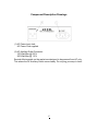
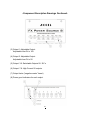
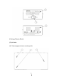
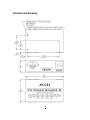
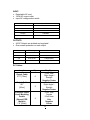
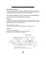
USER’S MANUAL Table of Contents What’s Included & Introduction .………..................1 General Information, Warnings & Cautions ............... 2 Warnings & Caution……………………………………..3-4 Component I.D. Drawing & Features……………........5-7 Power Supply Dimensional Drawing……………….. . 8 Specifications…………………………………………....9 Power Supply Mounting Instructions…………………10 Warranty…………………………………………………11 What’s Included (1) (1) (1) (2) (2) (6) (1) (3) Accel FX Power Source 8 Power Supply Users Manual AC Input cord 7.9” [20cm]Line 6 Converter Cables 19.7” [50 cm] Negative Center Output Cables 27.5” [70 cm] Negative Center Output Cables Power Supply Mounting Template M4 x 8 mm Mounting Screws Introduction: Your Accel ”FX Power Source 8” Eight Output Power Supply designed is with a high efficiency transformer. Each output is fully isolated, regulated and filtered with over voltage protection. Equipped with a voltage select switch, makes it work properly anywhere in the world (Read all Warnings, Cautions and input specifications). The all aluminum anodized enclosure dissipates the heat rapidly and keeps components cool. Accel’s "FX Power Source 8" mounts conveniently into the front load bay of all Accel pedal board modules with only three M4 mounting screws (supplied). The Power Source 8, powers 9V, 12V & 18V effects pedals. While there are 2 adjustable outputs (9V-18V & 5V-9V) and 4 selectable outputs (9V or 12V), 9V’s is available on all outputs to work with the majority of the pedals on the market. Read all warnings, cautions and operating instructions before using this product. To register your 5 year limited warranty. Please take a moment to fill out the supplied warranty card. 01 General information: (Quick View) 9V power options: Outputs 1 – 6; An effects pedal that has the option of being powered by a 9V battery requires less than 70mA and can be powered by any outputs 1-6 set to 9V. Outputs 7– 8p; Outputs 7 and 8 are designed for the higher current 9V effects pedals and switchers out on the market. 12V power options: Outputs: 3-6; When switched to 12V outputs 3,4,5,6 are designed to accepted BOSS ACA type pedals and some digital modeling pedals. 18V power option: Output 1; begins at 9V and can be adjusted and up to 18V for pedals that require 18V. Low Battery Simulation option: Output 2; can be adjusted from 9V down to 5V to be used to simulate a low battery which comes in handy if you have older transistor based distortion and fuzz pedals. Negative center polarity & positive center polarity barrel jacks. Most pedals on the market are designed with a “negative center” barrel jack. However there are a few pedal manufacturers out there that have positive center barrel jack designs. You can usually verify if the pedal is negative center (by far the most common) or positive center by simply flipping the unit over and looking at the label on the bottom of the unit. If the polarity is not shown, then consult the effects pedal manufacturer’s user’s manual or call their customer or technical support number. For those manufactures designs that are the exception and use a positive center polarity barrel jack, a polarity converter cable will need to be purchased. 02 Read all Warnings and Cautions before operating your FX Power Source 8 Power Supply 1. Keep these instructions – The safety and operating instructions should be retained for future reference. 2. All warnings, cautions and instructions should be adhered too for safe operation of your FX Power Source 8 Power Supply. 3. Follow all operating and use instructions for safe operation of this unit. 4. WARNING!!! The lightning flash with arrowhead symbol within an equilateral triangle is intended to alert the user to the presence of non-insulated “dangerous voltage” within the product’s enclosure that may be of sufficient magnitude to constitute a risk of electric shock. 5. WARNING!!! To reduce the risk of fire or electric shock, do not expose this power supply to rain or moisture. The unit should not be exposed to liquids of any kind. Any objects or containers filled with liquids, such as drinks or beverages shall not be placed on top of the unit. 6. WARNING!!! If you are mounting into a surface thicker than .125" [3.18mm] or thicker a longer screw may be required. Remember that Max protrusion depth into the power supply must be no more than .250" [6.35mm]. If this warning is not heeded , the presence of non-insulated “dangerous voltage” within the product’s enclosure may be of sufficient magnitude to constitute a risk of electric shock. 7. WARNING!!! Do not defeat the safety purpose of the grounding plug. A grounding plug has two blades and a third grounding prong. The grounding prong is provided for your safety. 8. WARNING!!! Set power supply selector switch to correct voltage before operating or risk of shock or death may occur. 9. WARNING!!! When operating this power supply in countries that require setting the selector switch to 220- 240V, make sure that correct countries AC cable plug end configuration is used (not supplied). If using an external voltage converter with the supplied North American AC cable with the power supply selector switch set at 110V, verify that the voltage converter instructions are followed and is not defective and in proper operating condition, before plugging in the FX power Source 8 to the voltage converter. Or risk of shock occur resulting in serious injury or death. 03 -Warnings and Cautions Continued- 10. CAUTION!!! The exclamation with arrowhead symbol within an equilateral triangle is intended to alert the users to the risk of damage to the FX Power Source 8 power supply if cautionary instructions are not followed. 11. CAUTION!!! To prevent risk of overheating or damage to the FX Power Source 8 power supply. Do Not Block any ventilation openings! The ventilation should not be impeded by covering the ventilation openings with items such as, tape, fabric, Velcro or any potentially flammable material. 12. CAUTION!!! To prevent risk of overheating or damage to the Power Source 8 power supply. Mount per the FX power Source 8 Mounting Instructions! 13. Clean only with a dry cloth. 14. Set selector switch to proper voltage before plugging in power supply. 15. Do not install near any heat sources that produce heat. 16. Protect the power cord from being walked on or pinched. Especially near the plugs, convenience receptacles, and at the point where they exit from the unit. 17. Follow all instructions and recommendations attachments/accessories specified by the manufacturer. regarding 18. Only use this unit as prescribed and specified by the manufacturer to power effects pedals. 19. Unplug the unit during lightning storms or when unused for long periods of time. 20. Refer all servicing to qualified personnel. Service is required when the power supply has been damaged in any way – such as power supply cord or plugs damage; if any liquid or foreign objects have gotten inside the unit; if it has been exposed to rain or moisture; has been dropped; or does not otherwise operate normally. 4 Component Description Drawings (1) AC Power Input Jack: AC Power Cord supplied. (2) AC Auxiliary Outlet Connector: 100 Watt Max @ 220 V 200 Watt Max @ 110 V Several effects pedals on the market are designed to be powered from AC only. This where the AC Auxiliary Outlet comes handy. Do not plug your amp in here! 5 -Component Description Drawings Continued- (3) Output 1: Adjustable Output: Adjustable from 9V to 18V (4) Output 2: Adjustable Output: Adjustable from 5V to 9V (5) Output: 3-6: Switchable Outputs 9V-12V’s (6) Output: 7-8: High Current 9V outputs. (7) Output Jacks (“negative center” barrel) (8) Power good indicators for each output. 6 (9) Voltage Selector Switch (10) Air Vents (11) Power supply customer mounting holes 7 Dimensional Drawing: 8 INPUT: Detachable AC cord 150W AC output outlet Input AC voltage select switch Country Input AC Volt North America 120V/60Hz Japan 100V/60Hz China 220/50Hz Europe 230/50Hz Australia 240/50Hz OUTPUTS: All DC Outputs are isolated and regulated Over current protection on each output Output DC Voltage Current 1 9V-18V 100mA-50mA 2 5V-9V 180mA-100mA 3-6 9.6V/12.4V 100mA/60mA 7, 8 9V 350mA DC Cables: Length Qty. Output Cable 27.5” [70cm] 6 Output Cable 19.7” [50cm] Converter Cable Line 6 Modeling Pedals (Except POD Models) 7.9” [20cm] 2 2 Plug Type 5.5x2.1mm Right Angle /Straight Negative Center 5.5x2.1mm Right Angle /Straight Negative Center 5.5x2.1mm Female 5.5x2.5mm Male Negative Center 9 FX Power Source Mounting Instructions Mounting pattern template For those who already have a different pedal board other than our Accel “Pro Compact” or “Pro Tier” modular series of pedal boards. A mounting template and our standard M4 thread mounting hardware have been provided. (The following “Warning” has been mention before in the Warnings & Caution pages and now re emphasized for you safety) Warning!!! If you are mounting into a surface thicker than .125" [3.18mm] or thicker, a longer screw may be required. Remember that Max protrusion depth into the power supply must be no more than .250" [6.35mm]. Do not drill into power supply. If these warnings are not heeded electrical shock or death may occur. Caution!!! Do not do not block air vents. Do not mount in an area where no air circulation is present. Do not mount in an enclosure with no ventilation (Metric dimensions are in millimeters & [ 10 ] brackets) Warranty Limited 5 Year Warranty This warranty covers any defects or malfunctions in your new Accel Power Source 8 Power Supply. This a 5 year warranty for the original registered purchaser. Accel will fix or replace any defective units with the first 5 years from the purchase date. Fixing or replacing the unit will be at Accels discretion. Any problem that is caused by abuse, misuse, or an act of God (such as a flood) are not covered. In order to be eligible for service under this warranty you must return the warranty registration card attached below within 30 days of purchasing the aid. If something goes wrong with your Accel Power Source 8 Power Supply, send it postage paid with a brief written description of the problem to: Accel Technologies LLC;. 5505 East Santa Ana Canyon Rd. #17057 Anaheim, CA 92817 This warranty gives you specific legal rights, and you may also have other rights which vary from state to state. Accel Technologies, LLC. P.O. BOX 17057 Anaheim, CA 92817 U.S.A. Email: [email protected] 11