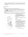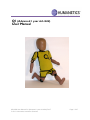
1
Q1 (Advanced 1 year old child) User Manual 036-9900 User Manual Q1 (Advanced 1 year old child) Rev E © 2011 Humanetics Innovative Solutions Page 1 of 67 For information on Humanetics products, please visit our web site at www.humaneticsatd.com or contact: Humanetics Innovative Solutions 47460 Galleon Drive Plymouth, MI 48170, USA Telephone: 734-451-7878 Fax: 734-451-9549 No part of this publication may be reproduced, stored in a retrieval system or transmitted in any form or by any means, electronic, photocopying, recording, mechanical or otherwise, without the express written consent of Humanetics Innovative Solutions. Copyright © 2011 Humanetics Innovative Solutions, All rights reserved. The information in this manual is furnished for informational use only, and is subject to change without notice. Humanetics Innovative Solutions assumes no responsibility or liability for any errors or inaccuracies that may appear in this manual. 036-9900 User Manual Q1 (Advanced 1 year old child) Rev E © 2011 Humanetics Innovative Solutions Page 2 of 67 Content 1. Introduction............................................................................................................................. 6 2. General Description and Features ........................................................................................ 7 2.1 Design History ..................................................................................................................................................................... 7 2.2 Application ............................................................................................................................................................................ 7 2.3 Features ................................................................................................................................................................................. 8 2.4 Instrumentation options Q1 dummy ............................................................................................................................. 9 2.5 Main Dimension .................................................................................................................................................................. 9 2.6 Mass Distribution ........................................................................................................................................................... 10 2.7 Standard Dummy ............................................................................................................................................................ 10 3. Instrumentation .................................................................................................................... 11 3.1 General ............................................................................................................................................................................... 11 3.2 Transducers ....................................................................................................................................................................... 11 3.3 Accelerometer Mounts ................................................................................................................................................... 13 3.4 Angular Velocity Sensor Mounting ....................................................................................................................................... 17 3.5 Cable routing and protection ........................................................................................................................................ 18 4. Assembly - Disassembly ....................................................................................................... 19 4.1 General Overview ............................................................................................................................................................. 19 4.2 Head .................................................................................................................................................................................... 19 4.3 Neck .................................................................................................................................................................................... 23 4.4 Torso .................................................................................................................................................................................... 26 4.5 Lumbar Spine .................................................................................................................................................................... 30 4.6 Pelvis .................................................................................................................................................................................... 34 4.7 Legs ...................................................................................................................................................................................... 37 4.8 Arms .................................................................................................................................................................................... 39 4.9 Abdomen ............................................................................................................................................................................ 41 4.10 Suit ....................................................................................................................................................................................... 41 5. Pre-Test Checks .................................................................................................................... 42 5.1 Inspection ........................................................................................................................................................................... 42 5.2 Click Stops and Arm adjustment ................................................................................................................................. 43 5.3 Time Interval between Tests ........................................................................................................................................ 43 6. Dummy Parts List ................................................................................................................. 44 7. Certification Equipment...................................................................................................... 47 036-9900 User Manual Q1 (Advanced 1 year old child) Rev E © 2011 Humanetics Innovative Solutions Page 3 of 67 8. 7.1 Requirements .................................................................................................................................................................... 47 7.2 Equipment.......................................................................................................................................................................... 48 7.3. Equipment Parts list ........................................................................................................................................................ 52 Certification Tests ............................................................................................................... 53 8.1 Head Certification ........................................................................................................................................................... 53 8.2 Certification of the Neck: .............................................................................................................................................. 56 8.3 Certification of the Lumbar Spine ............................................................................................................................... 59 8.4 Certification of the Abdomen ....................................................................................................................................... 62 8.5 Certification of the Thorax ............................................................................................................................................ 63 036-9900 User Manual Q1 (Advanced 1 year old child) Rev E © 2011 Humanetics Innovative Solutions Page 4 of 67 List of Figures Figure 1. Figure 2. Figure 3. Figure 4. Figure 5. Figure 6. Figure 7. Figure 8. Figure 9. Figure 10. Figure 11. Figure 12. Figure 13. Figure 14. Figure 15. Figure 16. Figure 17. Figure 18. Figure 19. Figure 20. Figure 21. Figure 22. Figure 23. Figure 24. Figure 25. Figure 26. Figure 27. Figure 28. Figure 29. Figure 30. Q-Dummy Family ....................................................................................................................................... 6 Accelerometer mounts for Q1 ............................................................................................................. 14 Three ATA ARS-06S sensor and mounts ........................................................................................... 17 Three Accelerometers and three DTS ARS-12K on mount ......................................................... 18 Head instrumentation - both accelerometer bracket arrangements ........................................... 18 Head Assembly with standard 020-1013 accelerometer mount .................................................. 20 Head Assembly including instrumentation ......................................................................................... 22 Neck Assembly ......................................................................................................................................... 23 Head and Neck ......................................................................................................................................... 25 Thorax Assembly ...................................................................................................................................... 27 String pot attachment .............................................................................................................................. 29 String pot Side impact bracket .............................................................................................................. 30 Lumbar Spine ............................................................................................................................................. 31 Tighten nut down on the lumbar.......................................................................................................... 32 Abdomen Assembly ................................................................................................................................. 33 Pelvis Assembly ......................................................................................................................................... 34 Hip Joint (Right) ........................................................................................................................................ 35 Hip Joint (Left)........................................................................................................................................... 36 Leg Assemblies, Right & Left .................................................................................................................. 38 Arm Assembly (Left)................................................................................................................................ 39 Arm Assembly (Right) ............................................................................................................................. 40 Q1 Full Body Impactor ............................................................................................................................ 48 Wire Suspension ....................................................................................................................................... 49 Head form .................................................................................................................................................. 50 Head form Lumbar Spine set-up ........................................................................................................... 51 Head drop Frontal.................................................................................................................................... 54 Head Drop Lateral ................................................................................................................................... 55 Lumbar Spine Frontal .............................................................................................................................. 60 Lumbar Spine Lateral ............................................................................................................................... 61 Abdomen Certification............................................................................................................................ 62 036-9900 User Manual Q1 (Advanced 1 year old child) Rev E © 2011 Humanetics Innovative Solutions Page 5 of 67 1. Introduction In the late 1970’s and early 1980’s, TNO and others developed the P-dummies, a series of child dummies that covers almost the complete child population up to 12 years. The P-series dummies are still test tools for the European regulation ECE-R44 and are also adopted by many other standards. In 1993 the international Child Dummy Working Group started with the development of a new series of child dummies as a successor to the P-series. This new series was called the Q-series. As of September 2004 the series is available in four age groups, representing a 1 year, 1½ year, 3 year and 6 year old child. A new born dummy, Q0 is also available. In 2004 a major update of the Q-dummy series has been performed resulting in the completion of the series from Q0 till Q6. The Q1.5 dummy and the Q0 were added to the series, and modifications were made to enhance durability and measurement capabilities. Part of the development of the Q-dummies has taken place within the European Research programs CREST1, and CHILD2 both aimed at improving child safety in cars. Humanetics reserves the right to make improvements or implement changes to the dummy, the certification or the users’ manual if this is deemed necessary. We will of course inform our customers of any changes or modifications as they occur. Figure 1. 1 2 Q-Dummy Family CREST. “Child Restraint System for Cars”. EC-contract number C-RTD SMT4-CT95-2019. 1996-2000. CHILD. “Child Injury Led Design”. EC contract number G3RD-CT2002-00791. 2002-2006. 036-9900 User Manual Q1 (Advanced 1 year old child) Rev E © 2011 Humanetics Innovative Solutions Page 6 of 67 2. General Description and Features 2.1 Design History In 1993 the international Child Dummy Working Group started with the development of a new series of child dummies as a successor to the P-series. This new series was called the Q-series. This development resulted in a Q3 dummy in 1998, later the Q6 (1999) and the Q1 (2000) were added to the series. Based on customer feedback and test results FTSS have received comments on the dummies performance and durability. This has resulted in an update program that was started in 2004; this update aimed at a number of issues with the Q dummies in the shoulder, and head/neck area. During this period the Q0 and Q1.5 were added to the family, based on Q-series anthropometry and biofidelity data. The European Enhanced Vehicle-safety Committee has performed an extensive evaluation program of the Q-series in 2004; a full report on a possible recommendation for use of the dummies in ECE-44 test was published in 2008. Results of the first evaluations have been published ant the 19th Enhanced Safety of Vehicles conference in 20053. In 2006 the New Programme for the Assessment of Child-restraint Systems (NPACS) adopted the Q dummies for their test protocols. 2.2 Application The Q-dummy is a frontal impact child dummy, which is intended for both homologation and research purposes. Possible applications include: Child Restraint Systems (CRS) testing. This includes the European ECE R44 and the US FMVSS 213 regulations. The Q-dummies have been designed to succeed the P-dummies in CRS evaluation regulations. EuroNCAP tests. The dummy has been designed to withstand impact with closing velocities up to an average EuroNCAP level. NPACS tests. The New Programme for the Assessment of Child-restraint Systems (NPACS) protocols calls up the Q series for their frontal and side impact consumer test procedures for CRS performance rating4. Out-of-position tests (OOP), including airbag interaction. ISO-side impact procedure. 3 ASSESSING NEW CHILD DUMMIES AND CRITERIA FOR CHILD OCCUPANT PROTECTION IN FRONTAL IMPACT, Kate de Jager, Michiel van Ratingen, TNO Science and Industry, Philippe Lesire, Hervé Guillemot, LAB (France), Claus Pastor, Britta Schnottale, BASt (Germany), Gonçal Tejera, Applus+IDIADA (Spain) Jean-Philippe Lepretre, UTAC (France). Paper no. 05-0157. 4 Progress Report and Results From the NPACS Research Project, R Lowne. Third International Conference on the Protection of Children in Cars, Munich, December 2005. 036-9900 User Manual Q1 (Advanced 1 year old child) Rev E © 2011 Humanetics Innovative Solutions Page 7 of 67 2.3 Features The Q dummies have improved biofidelity over the P-series. Biomechanical information from children and scaled adult biomechanical response curves have been used to define the dummy response. The anthropometry of the dummy has been based on CANDAT data. The dummies can be equipped with accelerometers, angular velocity sensors, load cells and displacement sensors. This allows evaluation of the injury risk under various circumstances. Special attention has been paid to the handling characteristics of the dummy, ensuring the dummy can be assembled and disassembled quickly, and installing the dummy in the test configuration is simple and repeatable. The influence of transducers upon the kinematics of the dummy is minimized, and protection of transducers and cables is integrated in the dummy design. Head The head is largely made from synthetics. The head cavity is large enough to allow use of several instruments, including linear accelerometers and angular velocity sensors. Neck The neck is flexible and allows shear and bending in all directions. The segmented design allows a realistic rotational behavior. The neck is equipped with low-stretch and high yield strength, low stretch synthetic fiber cord in order to prevent excessive elongation. The neck-cord is also designed to act a safety in case of rubber failure. A six channel load cell can be mounted at the neck-head interface. Thorax The thorax of the child is represented with a single rib-cage. The deformation can be measured with a string potentiometer. The shoulders are connected with a flexible joint to the thorax, allowing deformation forwards. Accelerometers can be mounted on the spine to measure linear accelerations. Abdomen The abdomen is foam covered with skin. Biomechanical data from children has been used to determine the required stiffness. Lumbar spine The lumbar spine is a flexible rubber column, which allows shear and bending in all directions. A six channel load cell can be mounted between the lumbar spine and the pelvis. Pelvis The Q-dummy pelvis has removable hip joints. An accelerometer array can be mounted in the pelvis. Special hip joints are available that allow to position the dummy in a standing position. Legs The knee joints can be locked in any position. This feature can be used to facilitate positioning the dummy in a standing position. Note that the dummy does not have the ability to stand without support. It must be placed against some object, such as the dashboard. 036-9900 User Manual Q1 (Advanced 1 year old child) Rev E © 2011 Humanetics Innovative Solutions Page 8 of 67 2.4 Instrumentation options Q1 dummy The complete list of instrumentation options include: Head Head Upper Neck Thoracic Spine Thorax Lower Lumbar Spine Pelvic 2.5 Ax, Ay, Az linear acceleration. Wx, Wy, Wz angular velocity. Fx, Fy, Fz forces and Mx, My, Mz moments. Ax, Ay, Az linear acceleration. 'ribcage' Dx or Dy deflection. Fx, Fy, Fz forces and Mx, My, Mz moments. Ax, Ay, Az linear acceleration. Main Dimensions The main dimensions of the Q-dummy series are described below. Nr Description ** 1 2 3 4 5 6 7 8 Sitting height (head tilted forward) Shoulder height Stature Chest depth * Shoulder width Hip width Buttock to front knee Buttock to popliteus, sitting Q1 Dimension [mm] Tolerance ± mm 479 298 740 114 227 191 211 161 9 7 9 5 9 7 5 9 *) the Chest depth is measured at the centre line of the string attachment of the displacement transducer. **) The measurements are valid for the dummy without suit. 036-9900 User Manual Q1 (Advanced 1 year old child) Rev E © 2011 Humanetics Innovative Solutions Page 9 of 67 2.6 Mass Distribution The table below shows the masses of the various components of the dummy. The masses given include accelerometer mounts, the string potentiometer or IR-TRACC and all screws and fixings. Q1 Mass [kg] Tolerance [kg] Head + neck (incl. acc. mount) Torso (incl. acc. Mounts, string pot-meter) Upper legs Lower legs Upper arms Lower arms Suit 2.41 4.21 1.00 0.82 0.45 0.44 0.27 0.10 0.25 0.10 0.10 0.10 0.10 0.05 Total 9.60 0.30 Component 2.7 Standard Dummy The standard Q-dummy is delivered with the following items: - One piece of clothing (a yellow suit); - Structural replacements in the location of the load cells; 036-9900 User Manual Q1 (Advanced 1 year old child) Rev E © 2011 Humanetics Innovative Solutions Page 10 of 67 3. Instrumentation 3.1 General The dummy accepts both accelerometers and load cells as standard instrumentation. Angular velocity sensors can be fitted to the head; this requires an alternative head accelerometer mount. The dummy can be equipped with uni-axial accelerometers for all locations. Tri-axial accelerometers can be used on the pelvis and thorax location. The load cells or its structural replacements are a part of the dummy structure; the structural replacements have to be used in absence of the actual transducer. A 6-channel load cell (FTSS model IF-217 or IF-218) can be placed in the upper neck and lumbar spine location. 3.2 Transducers The Q1 dummy can be fitted to measure of the following parameters: Head Standard Optional - 3 uni-axial accelerometers in head (Ax, Ay, Az) - 3 angular velocity: Applied Technologies Associates, ARS-06S -3 angular velocity DTS ARS-12K Neck Standard - Upper neck 6 channel load cell, 3 forces, 3 moments (Fx, Fy, Fz, Mx, My, FTSS Model IF-217 (350 Ohm) or IF-218 (120 Ohm). Mz). Thorax Standard Optional - 3 uni-axial accelerometers (or tria-xial accelerometer) in upper spine (Ax, Ay, Az). - 1 string potentiometer to measure chest deformation, frontal or lateral (Dx or Dy) - additional accelerometers may be installed on the thorax and the rib cage (see notes below) (Ax, Ay). Lumbar Spine Standard - 6 channel load cell at lumbar spine/ pelvis interface (Fx, Fy, Fz, Mx, My, Mz). FTSS Model IF-217 (350 Ohm) or IF-218 (120 Ohm). Pelvis Standard -3 uni-axial accelerometers (or tria-xial accelerometer) on pelvis skeletal structure (Ax, Ay, Az). 036-9900 User Manual Q1 (Advanced 1 year old child) Rev E © 2011 Humanetics Innovative Solutions Page 11 of 67 Notes: 1. The string potentiometer may be mounted in two ways, either to measure frontal or lateral deformations. The string potentiometer must not be used in deformations with expected ribdeformation speeds exceeding 5 m/s. 2. Information on the installation of the instrumentation can be found in the assembly/disassembly section of this manual. 3. The Upper Neck Load Cell does not require any correction for measurement of the moment around the OC joint. The (theoretical) OC joint coincides with the neutral axis of the moment measurement of the (FTSS) load cell. 4. Additional accelerometers may be mounted in the dummy for extra/redundant information. There are no fixed points for attaching these accelerometers. Instead, double-sided tape may be used to attach the accelerometer to the desired location. Two accelerometers may be used to measure deformation velocity and the deformation itself. The procedure is as follows: Install the accelerometers in the dummy. The sensitive axes of the transducers should be aligned as good as possible. Furthermore, the accelerometers should be installed in locations that are expected to retain their alignment during the deformation phase. Make sure that the accelerometers are not located on positions that may contact other parts of the dummy as a result of deformation. To process and combine the data first filter both signals at CFC1000 according to SAE J211. Subtract the signals and integrate the result. This results in the deformation velocity. Numerical integration of this signal gives the deformation itself. Note that this method gives an approximation of the actual deformation. The accuracy is decreased due to the fact that the accelerometers cannot be properly aligned during the test. Experience with the Q3 dummy shows that usage of the acceleration integration method results in an underestimation of the deformation. At 4.3 m/s initial impact velocity the error is approximately 10%. At 6.7 m/s it is approximately 20%. 036-9900 User Manual Q1 (Advanced 1 year old child) Rev E © 2011 Humanetics Innovative Solutions Page 12 of 67 3.3 Accelerometer Mounts FTSS support three brands/models of accelerometers or equivalent Endevco 7264 and 7267A series Entran EGAS Series and EGE3-73 Tri-axial. Kyowa ASM Series MSC 126M/CM Uni-axial accelerometers Note: The tria-xial accelerometers Endevco 7267A and Entran EGE3-073 cannot be fitted to the head. The head will only accept uni-axial accelerometers. Note: Thorax and Pelvis locations will ONLY accept tri-axial transducers with a side-entry cable. The following accelerometers ARS sensors and mounts can be used for the Q1 Dummy. Only Uni-axial accelerometers: Location Head mount (only Uni-axial accels) Head Mount for uni-accels & DTS ARS sensor (Optional) Head Mount for ATA ARS-06S sensor (optional) Head Mount for Uni-accels & ATA ARS-06S sensor (optional) Thorax Pelvis ENTRAN EGAS-FS-50 I.AD 036-1101 036-1251 I.AD & 036-1251 I.AO I.AO KYOWA ASM-200BA I.AM 034-1201 036-1251 I.AM & 036-1251 I.AN I.AN ENDEVCO 7264-2000 I.AM 034-1201 036-1251 I.AM & 036-1251 I.AN I.AN ENDEVCO 7264A/B-2000 I.AD 036-1101 036-1251 I.AD & 036-1251 I.AO I.AO MSC 126M/CM I.AM 034-1201 036-1251 I.AM & 036-1251 I.AN I.AN Head Mount (only Uni-axial accels) Head Mount for Uni-accels &DTS ARS sensor (Optional) Location Head Mount for ATA ARS-06S sensor (optional) Head Mount for Uni-accels & ATA ARS-06S sensor (optional) Thorax Pelvis Use Endevco Mount Base Use Endevco Mount Base Accelerometer Type Tri-axial: Accelerometer Type ENDEVCO 7264A-1500 Not Possible Not Possible Not Possible 036-9900 User Manual Q1 (Advanced 1 year old child) Rev E © 2011 Humanetics Innovative Solutions Not Possible Page 13 of 67 Figure 2. Accelerometer mounts for Q1 FTSS also support two models of angular: Applied Technologies Associates ARS-06S DTS ARS-12K Up Down Thorax accel mount, I.AO 036-9900 User Manual Q1 (Advanced 1 year old child) Rev E © 2011 Humanetics Innovative Solutions Page 14 of 67 Up Down Thorax accel mount, I.AN Front Rear Pelvis accel mount, I.AO 036-9900 User Manual Q1 (Advanced 1 year old child) Rev E © 2011 Humanetics Innovative Solutions Page 15 of 67 Front Rear Pelvis accel mount, I.AN Head accel mount, I.AD 036-9900 User Manual Q1 (Advanced 1 year old child) Rev E © 2011 Humanetics Innovative Solutions Page 16 of 67 Head accel mount, I.AM 3.4 Angular Velocity Sensor Mounting Three ATA sensors can be mounted in the head to measure three X, Y, and Z angular velocities (See Figure 3). The special mount is designed to mount three accelerometers and three DTS ARS 12K angular velocity sensors to measure three linear accelerations and three angular velocities along the X, Y, and Z Axis (See Figure 4). Figure 3. Three ATA ARS-06S sensor and mounts 036-9900 User Manual Q1 (Advanced 1 year old child) Rev E © 2011 Humanetics Innovative Solutions Page 17 of 67 Figure 4. Three Accelerometers and three DTS ARS-12K on mount Three DTS ARS series angular velocity sensors and three uni-accelerometers can be mounted on the mount block 036-1101 or 034-1201. This mount can be threaded to the standard mounting bracket (020-1013) in the head assembly as shown in Figure 5. Figure 5. Head instrumentation - both accelerometer bracket arrangements Application of the ATA ARS-06S angular velocity sensors in the head requires an alternative mount block assembly for the head, part no 020-1251 as shown in Figure 4. This block assembly will accept the same mount block as the standard accelerometer mounting for the head. 3.5 Cable routing and protection The Q1 dummy transducers have been designed and selected for use with small cross-section cables. These cables do not need much space and ensure minimum interference with the kinematics of the dummy. In the design of the Q1 dummy paths for the transducer cables have been defined. The general rule is that all cables should be routed towards the thoracic spine of the dummy. Cables should run from the top to the base of the thoracic spine. At the lumbar spine/thorax interface, the cables go either towards the left or the right side. The abdomen has been formed to allow the routing of the cables in such a way that they lie recessed between the rib cage and the pelvis skin. A cable cover is mounted on the back of the thoracic spine. This cover will protect the cables and provide a fixed contour of the back of the dummy. 036-9900 User Manual Q1 (Advanced 1 year old child) Rev E © 2011 Humanetics Innovative Solutions Page 18 of 67 4. Assembly - Disassembly 4.1 General Overview The Q-dummy consists of the following main components: head neck thorax lumbar spine abdomen pelvis arms legs The dummy is clothed in a tight-fitting suit. This suit is an integral part of the dummy and should be worn in all testing. A full description of the instrumentation capabilities is given in section 3. The tools needed for assembly and disassembly of the Q1-dummy are: screwdrivers metric hex keys. 4.2 Head Construction The components that constitute the (standard) head are: Description Head Assembly head front assembly. head rear assembly. accelerometer mounting base (standard) screws SHCS M3x40 screws SHCS M3x10 screws BHCS M5x12 Part No 036-1000 036-1020 048-1010 020-1013 5000649 5000119 5000565 Qty in Assembly 1 1 1 1 1 2 4 The head consists of two parts: the front assembly (skull and skin) and a rear assembly (skull cap). The rear assembly may be removed by unscrewing the four M5x12 button head cap screws located at the rear of the head. The head skin and skull are molded together and cannot be separated. The picture in the Head Assembly is shown that inside the head there is a large cavity which may be used to mount various types of instrumentation. The standard arrangement is to have the head mounting block bolted in the head which will accept 3 uni-axial accelerometers mount block sure the head accelerations. 036-9900 User Manual Q1 (Advanced 1 year old child) Rev E © 2011 Humanetics Innovative Solutions Page 19 of 67 048-1010 50001119 5000649 5000654 5000565 020-1013 036-1020 036-1000 Head assembly Figure 6. Head Assembly with standard 020-1013 accelerometer mount Assembly and Disassembly Disassembly The head is attached to the neck though the load cell or the structural replacement. To disassemble the head, remove first detach the load cell from the neck. Head 1. First remove the head rear assembly by unscrewing the four button head cap screws at the back of the head. 2. The accelerometer array can be removed in order to reach the screws in the upper neck load cell (or the load cell replacement). 3. With the accelerometer array removed, the M5 SHCS screws that attach the load cell to the neck can be reached through the top of the head. 4. Remove the head and upper neck load cell or structural replacement from the neck. 5. Turn the head upside down, and remove the FRCS screws at the base of the head. 036-9900 User Manual Q1 (Advanced 1 year old child) Rev E © 2011 Humanetics Innovative Solutions Page 20 of 67 Assembly Head The head can be assembled to the dummy by reversing the order of the disassembly. Instrumentation Standard Instrumentation 1. To install the accelerometers, first remove the head rear assembly by unscrewing the four M5x12 button head screws. 2. Remove the head accelerometer mounting block (020-1013), from the head cavity, by unscrewing the three cap head screws. 3. The uni-axial accelerometers must first be mounted onto a mounting block. 4. Bolt the mounting block onto head accelerometer block using the two socket head cap screws supplied with the mount. Mount the interface inside the head front assembly. Figure 5. Replace the head rear assembly and tighten the four bolts. Note: As shown in the head assembly section, it is advised mount the head onto the neck, before placing the accelerometers in the head cavity. To remove the accelerometers, the procedure described above must be performed in the reverse order. Alternative instrumentation The cavity in a Q-dummy head is large enough to accept an array of angular velocity sensors, DTS ARS series and ATA ARS-06S (Figures 3 and 4). The combination with accelerometers are possible for both. To assemble the ATA Sensors, the standard mounting bracket (020-1013) should be removed. The ATA mount assembly 036-1250 then can be mounted to the head bracket as Figure 4 displayed. 036-9900 User Manual Q1 (Advanced 1 year old child) Rev E © 2011 Humanetics Innovative Solutions Page 21 of 67 Figure 7. Head Assembly including instrumentation 036-9900 User Manual Q1 (Advanced 1 year old child) Rev E © 2011 Humanetics Innovative Solutions Page 22 of 67 4.3 Neck Construction The neck assembly consists of the following parts (from top to bottom): Description Part No Qty in Assembly Neck Assembly Tested and Certified Neck Molded, pre-tested Neck cable assembly Nut Screws FHCS M3 x 8 020-2100 020-2101 020-2200 020-2204 5000116 1 1 1 1 2 5000116 020-2200 020-2101 The main part of the neck assembly consists of a rubber column, with bonded metal interface plates attached to the top and bottom. The neck assembly has four threaded inserts in the top surface which are used to mount the upper neck load cell (FTSS model IF-217) onto the neck. The upper neck plate has two cut-outs towards the rear to allow proper routing of the upper neck load cell cables. In case the load cell is not used, a load cell structural replacement (020-2007) with identical shape and mass is installed onto the neck. The neck cable assembly contains high yield strength, low stretch synthetic fiber cord. This neck cable assembly is tested and pre-stretched to ensure the correct length and the performance of the neck assembly. The cable assembly should not be disassembled by the user. The neck cable will act as a safety measure in case of rubber failure. 5000291 020-2204 (included in 020-2200 assemnbly) Neck Assembly 020-2100 Figure 8. Neck Assembly 036-9900 User Manual Q1 (Advanced 1 year old child) Rev E © 2011 Humanetics Innovative Solutions Page 23 of 67 Assembly and Disassembly Disassembly Head & Neck 1. To disassemble the neck, remove the head and upper neck load cell structural replacement as described above. 2. After removing the head assembly and load cell structural replacement, the screws at the base of the neck can be reached and removed. 3. To inspect the neck-cable assembly, remove the two FHCS M3 x 8 at the top of the neck and undo the nut at the bottom of the neck. The Neck-cable assembly can now be pulled out from the top. The neck cable assembly should NOT be disassembled. Note: Do not unscrew the screws that secure the clamping plates to the neck cable assembly. The neck cable is pre-stretched and clamped down at manufacturing, and should not be disassembled. In case of cable damage, customers are requested to replace the complete neck cable assembly (020-2200). Assembly Head & Neck 1. Perform the steps described under disassembly in reverse order. Instrumentation 1. To install a load cell, first remove the load cell structural replacement. To do so, remove the head as shown above. 2. Remove the four M5x10 FHCS screws that attach the load cell to the base of the head assembly. 3. Remove the load cell structural replacement and install the load cell (FTSS type IF-217 or IF-218). The round base plate should be facing up, and the cable exits facing downwards at the rear and the back of the neck. 4. Fasten the load cell to the base of the head using the four M5x10 counter sunk head cap screws. 5. Assemble head and Load cell onto the top of the neck using the four M5 x 12 SHCS screws. Note: Always mount the upper neck load cell BEFORE the head accelerometers, as the accelerometer array will block the top access to the screws through the top of the head. 036-9900 User Manual Q1 (Advanced 1 year old child) Rev E © 2011 Humanetics Innovative Solutions Page 24 of 67 036-1000 5000291 020-2007 020-2100 5000291 Head and Neck assembly Figure 9. Head and Neck 036-9900 User Manual Q1 (Advanced 1 year old child) Rev E © 2011 Humanetics Innovative Solutions Page 25 of 67 4.4 Torso Construction The torso consists of a metal thoracic spine, left and right shoulder assemblies, a clavicle and a rib section. The rib cage is made of a deformable synthetic composite. The shoulders are connected with the clavicle element, which attaches to the left and right shoulders, and to the rib cage (sternum). The parts of the Thorax assembly are listed below. A picture can be found in Thorax. Description Neck Torso Interface plate Thorax assembly Rib Cage Assembly tested Clavicle Molding Shoulder Spine Interface assy RH (rubber) Shoulder Spine Interface Assy LH (rubber) Clavicle Retainer Side String Pot Caddy Q1.5 Shoulder Ball Retaining Ring Shoulder Ball Thoracic Spine String Pot Caddy String Potentiometer attachment Shoulder Washer Rubber * Shoulder Washer * Cable Tray Inner Cable Tray Outer Screw M4x10 BHCS Screw M5x8 FHCS Screw M5x16 BHCS Screw M5x12 FHCS Screw M3x12 FHCS Lumbar Spine Mounting Screw Screw M5x0 .8x10 FHCS Part No 036-2003 036-4000 036-4100 048-3010 048-3011 048-3015 048-3005 048-3103 036-3002 036-3004 036-4001 036-4002 036-4003 036-3005 036-3006 036-4301 036-4302 5000005 5000662 5000416 5000096 5000415 020-9902 5000084 Qty in Assembly 1 1 1 1 1 1 1 1 2 2 1 1 1 6 6 1 1 6 6 8 2 4 2 4 *) Items marked are not shown in Thorax, but in Top Assembly Assembly and Disassembly Disassembly Upper/Lower Torso 1. The suit should be removed for proper access to the thorax assembly. 2. Remove the cable cover (036-4302) at the back of the thoracic spine (036-4001). 3. The upper part of the body can easily be separated from the lower part of the body by removing the two M6x43 (020-9902) counter-sunk located at the base of the thoracic spine. First loosen the two bottom screws at the base of the rib assembly than unscrew and remove the M6x43 (020-9902) counter sunk screws. The upper body can then be lifted from the lower part of the dummy. 036-9900 User Manual Q1 (Advanced 1 year old child) Rev E © 2011 Humanetics Innovative Solutions Page 26 of 67 Note: When operating on the upper torso section of the dummy, for example when installing or removing components or installing instrumentation, it is convenient first to remove the head and neck (see the paragraphs above for the procedure how to do this), and then divide the dummy in two parts by removing the thorax/lumbar spine screws. This gives easy access to the internals of the upper torso and to the various bolts and screws. 036-3002 036-3004 5000662 048-3010 5000662 036-3002 036-3004 036-4302 5000416 036-4301 048-3005 5000415 048-3011 5000416 5000005 5000084 036-2003 5000005 048-3015 5000096 036-4001 5000416 036-4100 Figure 10. Thorax Assembly The parts list for the torso assembly is shown on the previous page Note: To prevent unnecessary wear, the rib cage and shoulders should not be removed from the thoracic spine under normal circumstances. 036-9900 User Manual Q1 (Advanced 1 year old child) Rev E © 2011 Humanetics Innovative Solutions Page 27 of 67 Arms To remove the arms turn the dummy sideways and remove the three M3 SHCS in the arm (see also section 4.8). Repeat this procedure for the other arm. Note the position of the steel and rubber washers for the arm friction setting (See figure 17 and 18). 1. Arm Assembly (R and Arm Assembly (L). Clavicle 2. The clavicle is attached to the shoulder spine interface with three M5 x 8 countersunk screws on each side. Remove these screws by turning the aluminum retaining ring until the screws become visible. 3. Remove the M5x12 countersunk head screw at the front of the rib cage which is used to mount the clavicle retainer (048-3005) and clamps the clavicle to the rib cage. Remove the screw and the clavicle retainer on the inside of the rib. Rib 4. Remove the rib by unscrewing the six M5x16 button head cap screws on each side of the thoracic spine. Shoulders 5. Finally, the shoulder spine interfaces (048-3011 & 048-3015) can be removed by unscrewing the three M4x10 button head cap screws of each shoulder spine interface. Assembly To assemble the thorax, perform the operation described above in reverse order. Note: The shoulder should be set to the 1-2 G friction setting; this can be done by tightening or loosening the three M3 SHCS. See section 4.8 of this manual. Instrumentation Standard Instrumentation Accelerometers The thorax can be equipped with three uni-axial accelerometers or a tri-axial accelerometer in the cavity located at the back and top of the thoracic spine. 1. The uni-axial accelerometer must first be mounted onto the specified mounting block. The tri-axial accelerometer should be mounted using a mounting base (Endevco type 23898). 2. Use two SHCS M3 x 8 screws to attach the mounting block inside the cavity. The longest side of the mounting base should be facing upwards. 036-9900 User Manual Q1 (Advanced 1 year old child) Rev E © 2011 Humanetics Innovative Solutions Page 28 of 67 Load cell 1. The Q1 dummy cannot be equipped with a lower neck load cell. String Potentiometer The thoracic spine can be equipped with a string potentiometer which fits into the cavity directly below the cavity for the accelerometers. The string potentiometer is always used in combination with a string potentiometer caddy. The string potentiometer is mounted onto this caddy using two imperial 2-56 counter-sunk screws. The string potentiometer can be used for both frontal and side impact. Figure 11. String pot attachment Frontal Impacts 1. To use the string potentiometer for frontal impacts, insert the string potentiometer caddy into the cavity in the spine from the rear. The transducer signal cable should exit the cavity at the rear, the string of the potentiometer at the front (top). 2. The string potentiometer caddy is fixed using the two M3x16 screws. 3. Pull out the string towards the sternum of the ribcage and put the ball in the socket of the string potentiometer attachment. 4. Pull string potentiometer attachment towards the ribcage and align string attachment with the hole in the ribcage. 5. Insert screw in the hole and screw string attachment to the ribcage assembly. 6. To dismount the string potentiometer, perform steps 1-4 in reverse order. 036-9900 User Manual Q1 (Advanced 1 year old child) Rev E © 2011 Humanetics Innovative Solutions Page 29 of 67 048-3101 FHCS 2-56x3/8 5000312 048-3103 IH-170* *) IH-170 Not included with dummy purchase FHCS 2-56x5/16 Figure 12. String pot Side impact bracket Note: A spring is used to keep tension on the string potentiometer cable. When dismounting the string potentiometer from the rib, gently let the cable be reeled in by the spring. Releasing the cable while it is pulled out will cause serious damage the string potentiometer. Side Impacts 1. To use the string potentiometer for side impact, remove the string potentiometer caddy from the cavity in the thoracic spine. Remove the string potentiometer from its caddy. The string potentiometer can be used for left and right sided impacts by mounting the potentiometer on the right of left side. 2. Fasten the string potentiometer on the side impact caddy (048-3103) using the two imperial 2-56 screws. Note that the 2-56 x 3/8 screws are used at the top, while a shorter 2-56 x 5/16 screw is used at the bottom hole. 3. Attach the caddy to the thoracic spine, using the two M3 x 20 SHCS screws. 4. Pull out the string towards the rib, and put the ball in the socket of the string potentiometer attachment. 5. Insert the screw though the rib and fasten the string potentiometer attachment to the rib cage assembly. 6. To remove the string potentiometer, perform steps 2-4 in reverse order and fasten the string potentiometer attachment to the rib. 4.5 Lumbar Spine Construction The lumbar spine consists of lumbar spine central molding cable assembly load cell structural replacement screws (M5x12) 036-9900 User Manual Q1 (Advanced 1 year old child) Rev E © 2011 Humanetics Innovative Solutions Page 30 of 67 The lumbar spine assembly consists of a rubber column with metal interfaces bonded to the top and bottom. The top interface is U-shaped (vertical elements at the front and back). The thoracic spine fits into this bracket and is secured using the two M6x43 screws. At the bottom side, four M5x12 cap head screws are used to attach the lumbar spine assembly to either the model IF-217 load cell or the load cell structural replacement. The lumbar spine assembly has a cable fitted through the centre. This is used to pre-tension the spine to achieve the correct dynamic properties, and as a security measure (protection in case of lumbar spine damage or failure). Description Part No Lumbar Spine Assembly (tested and certified) Lumbar Spine central molding, pre-tested Lumbar Cable M6 Nylon nut M6 Plain Washer Screw SHCS M5 x 12 036-6000 036-6001 020-6100 5000093 5000094 5000002 Qty in assembly 1 1 1 1 1 4 Assembly and Disassembly Disassembly 5000093 5000094 036-6001 1. Remove the upper torso by removing the two M6x43 screws at the thoracic spine/lumbar spine interface as shown in Figure 9. 2. Remove the four M5x12 countersunk head screws, which are used to fasten the load cell (or structural replacement) to the pelvis. 3. Remove the load cell (or load cell structural replacement). From the lumbar spine by removing the four M5x12 socket head cap screws. 4. The cable assembly should not need to be removed under normal circumstances. Should it become necessary, use a screwdriver in the slot at the top of the cable to prevent the cable from turning, and unscrew the self-locking nut with a spanner. 5000002 020-6100 Lumbar spine assembly Figure 13. Lumbar Spine 036-9900 User Manual Q1 (Advanced 1 year old child) Rev E © 2011 Humanetics Innovative Solutions Page 31 of 67 Figure 14. Tighten nut down on the lumbar Assembly 1. Perform steps 1-3 or 4 under "disassembly" in reverse order. Instrumentation Load cell An FTSS IF-217 or IF-218 6-Axis Load cell may be mounted between the lumbar spine and pelvis. This load cell replaces the 020-2007 load cell replacement as shown in the Abdomen below. 1. To do so, first remove the upper torso from the lumbar spine by removing the two M6x43 screws. 2. Then unscrew the four M5x12 counter-sunk head screws attaching the structural replacement to the pelvis. Remove the lumbar spine/structural replacement assembly from the pelvis casting. 3. Unscrew the four M5x12 screws to remove the structural replacement from the lumbar spine. 4. Now, replace the structural replacement by the actual load cell and fix the four M5x12 cap head screws. The base plate of the load cell should be facing down, and the cable exits at the rear of the dummy when the assembly is put onto the pelvis casting. 5. Mount the assembly onto the pelvis casting using four M5x12 counter sunk screws. 036-9900 User Manual Q1 (Advanced 1 year old child) Rev E © 2011 Humanetics Innovative Solutions Page 32 of 67 036-5000 020-9902 036-6000 020-2007 5000084 5000002 Abdomen and Lumbar Spine assembly Figure 15. Abdomen Assembly 036-9900 User Manual Q1 (Advanced 1 year old child) Rev E © 2011 Humanetics Innovative Solutions Page 33 of 67 4.6 Pelvis Construction The pelvis assembly consists of: Description Part No Qty in Assembly 1 1 1 1 1 4 8 036-7000 Pelvis assembly 036-7001 Pelvis casting machined 036-7002 Pelvis Flesh Hip joint assembly Left 020-7100 Hip joint assembly Right 020-7110 Screw M5x10 FHCS* 5000084 Screw M5x12 SHCS** 5000002 * These screws are shown in the Abdomen: ** 4 psc are shown in Pelvis below, 4 psc are shown in the Abdomen. 036-7001 020-7100 020-7110 036-7001 5000002 036-7002 Pelvis assembly Figure 16. Pelvis Assembly The pelvis casting is a single metal casting which fits into the pelvis flesh. The two items are completely separable. The upper leg, with the ball and socket hip joint assemblies fit into the two openings at the left and right side of the pelvis. 036-9900 User Manual Q1 (Advanced 1 year old child) Rev E © 2011 Humanetics Innovative Solutions Page 34 of 67 Assembly and Disassembly Disassembly Start 1. If necessary, remove the dummy’s upper part, by removing the M6x43 bolts (020-9902) at the lumbar spine thorax interface. 2. Remove the lumbar spine and load cell (or load cell structural replacement) as described in §3.5. Legs 3. Remove the left and right legs. To do so, put the dummy on its back or chest, and remove the two M5x12 screws in the crotch area (left and right - four screws total). These screws are used to retain the hip joint assemblies. 4. With the screws removed from the dummy, the legs can be removed from the pelvis by pulling them laterally outwards. Skin 5. When the legs are removed, the pelvis flesh can be removed from the pelvis casting by pulling it downwards. The pelvis casting is now exposed (see Pelvis. Note: It is not possible to change the friction setting of the hip-joints. The legs are fully supported and positioned by the child restraint system. 020-7103 5000650 020-7112 020-71111 500065 020-7104 500065 Hip Joint assembly Right 020-7110 Figure 17. Hip Joint (Right) 036-9900 User Manual Q1 (Advanced 1 year old child) Rev E © 2011 Humanetics Innovative Solutions Page 35 of 67 Description Part No Left Hip Joint Assembly L or R 020-7100 020-7101 020-7102 Hip Joint Lower L or R Hip Joint Upper L or R Detent Peg Spring Retainer Plate Spring Screw M3x8 BHCS Screw M3x6 FHCS Part No Right Qty in each Assy 020-7110 020-7111 020-7112 020-7103 020-7104 5000650 5000410 5000098 1 1 1 1 1 1 2 2 020-7103 020-7102 5000650 020-7101 5000098 5000410 020-7104 Hip Joint assembly Left 020-7100 Figure 18. Hip Joint (Left) Instrumentation Accelerometers The pelvis can be equipped with a mounting block accepting three uni-axial accelerometers or a single triaxial accelerometer. In order to use accelerometers in the pelvis, first mount them onto the mounting block, the tri-axial accelerometer should be mounted on a mounting plate. Then remove the pelvis flesh as outlined in the paragraph above (assembly and disassembly). The mounting block should be attached at the inferior surface at the bottom of the pelvis casting, with the long side of the base plate facing backwards. The cables should be routed forwards through the pubic area when replacing the pelvis flesh. 036-9900 User Manual Q1 (Advanced 1 year old child) Rev E © 2011 Humanetics Innovative Solutions Page 36 of 67 4.7 Legs Construction The legs consist of an upper leg and lower leg connected to each other with a knee joint. At the hip side, a ball and socket joint is used. This joint should not be taken apart under normal operating circumstances. In the knee joint, a limited range of motion has been built in. At the end of this range, rubber stops are used to smoothly decelerate the motion and thereby preventing spikes on the measurement signals. Description Leg assembly L or R Upper Leg Assembly L or R Lower Leg Assembly L or R Shoulder Screw, modified Stop Screw Part No Left 036-9100 036-9101 036-9102 Part No Right 036-9200 036-9201 036-9202 036-9901 020-9901 Qty in each Assy 1 1 1 1 1 Assembly and Disassembly Disassembly It is not advised to disassemble the legs, except to replace broken parts. To separate the lower from the upper leg: 1. Remove the motion stop screw (020-9901) located on the inside of the knee joint. 2. Remove the modified shoulder screw (036-9901) connecting the two parts of the leg. Assembly 1. Check that the rubber end stops are in the correct position inside the upper knee joint before assembly of the lower leg. 2. Align upper and lower leg at shoulder screw holes and screw in shoulder screw. 3. Before inserting the motion stop screw, place upper and lower leg in a 90º angle with respect to each other. 4. Turn the motion stop screw into the leg as far as it will go. Then turn it back half a turn and check that the motion of the lower leg is without significant friction. Note: It is not possible to change the friction setting of the knee joint in the legs. The legs are fully supported and positioned by the child restraint system. 036-9900 User Manual Q1 (Advanced 1 year old child) Rev E © 2011 Humanetics Innovative Solutions Page 37 of 67 Figure 19. Leg Assemblies, Right & Left Instrumentation No instrumentation is used in the legs. 036-9900 User Manual Q1 (Advanced 1 year old child) Rev E © 2011 Humanetics Innovative Solutions Page 38 of 67 4.8 Arms Construction The arms consist of an upper and lower section, connected at the elbow with a joint. At the upper end, a shoulder joint allows a number of degrees of freedom. The main joint is of the ball-and socket type, with a limited range of motion. The upper arm can rotate around its vertical axis. 036-3005 Furthermore, the entire arm can rotate Rubber washer around the shoulder lateral axis. 5000119 Arm Assembly (Left shows all the parts used in the arm assembly. The 1-2 G setting of the arm to shoulder joint can be changed by tightening or loosening the M3 attachment screws. The compression washers ensure a certain amount of pressure on the screws and prevent them from loosening. Slots in the retaining ring have been provided to indicate horizontal and vertical positions of the upper arm. At the elbow joint, the range of motion is limited. At the end of the range of motion, rubber stops in the joint ensure a smooth arrest of motion. This prevents hard contact and reduces spikes on measurement signals. A “click stop” provides a fixed position for the lower arm when setting up the dummy. 036-9301 036-3006 Steel washer 5000328 5000626 036-9901 036-9901 020-9901 036-9302 Arm assembly Left Figure 20. Arm Assembly (Left) Description Arm Assembly L or R Upper Arm Assembly L or R Lower Arm Assembly L or R Shoulder Screw, modified Stop Screw Click Stop Part No Left 036-9300 036-9301 036-9302 Shoulder Ball Retaining Ring Shoulder Ball Screw SHCS M3 x 10 Steel Washer Rubber Washer 036-9900 User Manual Q1 (Advanced 1 year old child) Rev E © 2011 Humanetics Innovative Solutions Part No Right Qty in each Assy 036-9400 036-9401 036-9402 036-9901 020-9901 5000328 1 1 1 1 1 1 036-3002 036-3004 5000119 020-3006 020-3005 2 1 3 3 3 Page 39 of 67 Assembly and Disassembly Disassembly 1. remove the arm assembly by removing the three M3 screws at the top of the upper arm. It is recommended NOT to undo the shoulder ball. 2. remove the spring plunger and motion stop screw. 3. remove the modified shoulder screw connecting upper and lower parts of the arm Assembly 036-3005 Rubber washer 5000119 036-9301 036-9401 036-3006 Steel washer 5000328 036-9901 020-9901 5000626 036-9901 036-9402 Arm assembly Right 1. Perform steps 1-3 under assembly in reverse order. Make sure that the retaining ring is in the right position, with one slot facing downward, and the other facing rear ward. 2. Check that the rubber end stops are in the correct position inside the elbow joint before assembly of the lower arm. 3. Align upper and lower arm at the shoulder screw hole and screw in shoulder screw (036-9901). 4. Place upper and lower arm under a 90º angle with respect to each other. 5. Turn the motion stop screw (0209901) into the arm as far as it will go. Then turn back half a turn and check that the motion of the lower arm is without significant friction. The correct position for motion stop screw is the inside of the arm. 6. Screw in the spring plunger (5000328) in the hole next to the shoulder screw at the outside of the arm. 7. Check the correct settings for the spring plungers (see chapter 5). Figure 21. Arm Assembly (Right) Note: It is not possible to change the friction setting of the elbow joint. The positioning is done by means of the fixed “click stop” positions in the joint. 036-9900 User Manual Q1 (Advanced 1 year old child) Rev E © 2011 Humanetics Innovative Solutions Page 40 of 67 Instrumentation No instrumentation is used in the arms. 4.9 Abdomen Construction The abdomen (036-5000) consists of one part, skinned foam, which is inserted between the pelvis and rib cage. It allows significant deformation of the dummy in the abdominal area. See Abdomen Assembly and Disassembly Disassembly To properly remove the abdomen from the dummy; the following steps should be taken: 1. Remove the upper part of the dummy from the lower part (see procedure under lumbar spine and/or thorax paragraphs), by removing the two M6x43 screws from the lumbar spine thorax interface. 2. The abdomen can then easily be taken from the dummy. Note: It is not advised to remove the abdomen from the assembled dummy, as this places forces and strains upon the material, which can in time result in wear and tear. Removing the abdomen as outlined in this paragraph greatly enhances the durability of the abdomen. Assembly 1. The dummy should be divided into the upper and lower half by unscrewing the two M6x43 screws at the lumbar spine. 2. Insert the abdomen into the pelvis. 3. Put the top of the dummy (thorax and head) back on the lumbar spine with the two M6x43 screws at the lumbar spine. Instrumentation No instrumentation is used in the abdomen. 4.10 Suit The dummy is clothed in a tight-fitting neoprene suit (part no. 036-8000). This suit is an integral part of the dummy and should be worn in all tests. To put the suit on, first put on the lower half, legs first, and pull the pants section well into the crotch of the dummy. Then put the arms through the sleeves of the suit and pull it upwards. Close the suit at the back using the hook and loop fasteners (Velcro). The dummy does not wear shoes. 036-9900 User Manual Q1 (Advanced 1 year old child) Rev E © 2011 Humanetics Innovative Solutions Page 41 of 67 5. Pre-Test Checks 5.1 Inspection Before performing a test, a visual inspection of the dummy should be made. Special attention should be paid to the following items. Neck The rubber-molded part of the neck should not be damaged, that is: it should be complete and not show any tear and wear. By bending the neck slightly small cracks can also be detected. The neck cable should be checked carefully to check that there is no visible damage to the cord. Lumbar Spine The lumbar spine rubber may not be damaged. Inspect the rubber molding for tears and cracks. Replace if the spine is damaged. The cable must be inserted and the nut at the top properly screwed on. Abdomen The abdomen should be checked periodically (10 tests) for tearing of the PVC skin. Note that the wear of the abdomen is greatly reduced by observing the proper installation procedure. First remove the upper torso. The abdomen can then be removed by simply lifting it out of the pelvis. Shoulders Periodically examine the shoulder to spine interface for damage. Arms: Check the friction setting of the shoulder-arm regularly positions. Clavicles Inspect the clavicles for cracks in the material. Rib Cage Check the rib cage for tears and cracks in the material. Deform the rib by hand, as this will show cracks if present. Spring Plungers Check the spring plungers in the elbows. See paragraph 4.2 for instructions. 036-9900 User Manual Q1 (Advanced 1 year old child) Rev E © 2011 Humanetics Innovative Solutions Page 42 of 67 5.2 Click Stops and Arm adjustment Arm adjustment The correct arm-shoulder friction can be set by tightening or loosening the M3 screws in the upper arm. Rubber Friction washers (036-3005) have been placed between the upper arm and retaining ring, to ensure a certain amount of pressure at all times. This will prevent the shoulder screws from loosening in normal use. To set the correct 1-2 G setting of the shoulder joint, tighten the M3 screws evenly until the correct setting has been found. Elbow: The spring plungers (click stops) in the elbow joint should keep the lower arm in one of two defined positions when a torque exerted by the lower arm mass and gravity is exerted upon the joint. Adjust the click-stop by making small adjustments with a screwdriver. If the setting is correct, the arm should stay in its position even when small forces are exerted upon it, but start to rotate when significant accelerations are experienced. To verify this, push against the arm to force the arm out of the click stop position. If the click-stops are screwed in too far, the friction between them and the arm will be too large and the arm will not rotate under gravitation. 5.3 Time Interval between Tests When conducting tests with the dummy or with dummy components a time-interval of at least 30 minutes should be observed between consecutive tests. This also applies when, for example, a lateral test is followed by a frontal test using the same dummy component. Special attention 1. Always provide sufficient slack in the cables to allow the dummy to deform without putting any strain on the cables. This is especially important for the instrumentation located in the head (accelerometers, load cell). Please note that the slack can cause the cables so snag behind some other object in the test-set-up and which can result in damage of the head instrumentation. It is strongly recommended to include a strong guide cable in the cable bundle, especially when head instrumentation is used. This cable can be attached to the rear hole of the structural replacement or load cell and attached to the transducer cables with tape or tie-wraps. 036-9900 User Manual Q1 (Advanced 1 year old child) Rev E © 2011 Humanetics Innovative Solutions Page 43 of 67 6. Dummy Parts List Part No. 036-0000 Description Q1 DUMMY TESTED/CERTIFIED, UNINSTRUMENTED Qty per dummy Remark 1 036-1000 036-1020 048-1010 5000565 020-1013 5000119 5000649 Head Assembly Head Front Assembly Head Rear Cap Assy Screw M5x12 BHCS Head Accl Bracket Screw M3x10 SHCS Screw M3x40 SHCS 1 1 1 4 1 2 1 020-2007 036-2003 Load Cell Structural replacement Neck Torso Interface Plate 1 1 020-2100 020-2101 020-2200 5000116 Neck Assembly Tested / Certified Neck Moulding pre-tested Neck Cord Assembly Screw, M3 x .5 x 8 FHCS 1 1 1 2 5000291 M5x10 SHCS 8 5000084 M5x10 FHCS 8 036-4000 036-4100 048-3010 048-3011 048-3015 048-3005 036-3002 036-3004 036-4001 036-4002 036-4003 036-3005 036-3006 048-3200 5000005 5000096 5000662 5000416 5000415 5000437 036-4031 036-4032 036-5000 Torso Assembly Tested/Certified Rib Cage Assembly tested Clavicle Moulding Shoulder Spine Interface assy RH (rubber) Shoulder Spine Interface Assy LH (rubber) Clavicle Retainer Shoulder Ball Retaining Ring Shoulder Ball Thoracic Spine String Pot Caddy String Pot Mount Shoulder Friction Washer Shoulder Washer Cable Tray Screw M4x12 BHCS Screw M5x12 FHCS Screw M5x8 FHCS Screw M5x16 BHCS Screw M3x12 BHCS Screw M3x16 SHCS Cable Guide Outer Cable Tray Outer Abdomen Tested/Certified 036-9900 User Manual Q1 (Advanced 1 year old child) Rev E © 2011 Humanetics Innovative Solutions Rear Cap to Head front assembly Head accl bracket to head Head accl bracket to head Neck to thoracic spine & Structural repl. to neck Structural repl. to head.& Neck Torso Interface to thoracic spine 1 1 1 1 1 1 2 2 1 1 1 6 6 1 6 2 6 8 10 2 1 1 1 Page 44 of 67 Part No. Description Qty per dummy Remark 036-6000 036-6001 020-6100 5000093 5000094 020-9902 Lumbar Spine Assembly Lumbar Spine Central Moulding Lumbar Cable Assembly M6 Nyloc nut 6 Plain Washer Lumber Spine Mounting Screw 1 1 1 1 1 2 036-7000 036-7001 036-7002 020-2007 5000084 Pelvis Assembly Pelvis bone machined Pelvis Flesh Load cell Structural replacement Screw M5x10 FHCS 1 1 1 1 4 5000002 Screw M5x12 SHCS 4 020-7100 020-7101 020-7102 020-7103 020-7104 5000650 5000653 5000098 5000002 Hip Joint Assembly LH Hip Joint Lower Left Hip Joint Upper Left Detent Peg Spring Retainer Plate Spring Screw M3x8 BHCS Screw M3x6 FHCS Screw M5x12 SHCS 1 1 1 1 1 1 2 2 2 020-7110 020-7111 020-7112 020-7103 020-7104 5000650 5000653 5000098 5000002 Hip Joint Assembly RH Hip Joint Lower Right Hip Joint Upper Right Detent Peg Spring Retainer Plate Spring Screw M3x8 BHCS Screw M3x6 FHCS Screw M5x12 SHCS 1 1 1 1 1 1 2 2 2 036-8000 Suit 1 036-9100 036-9101 036-9102 5000626 020-9901 Leg Assembly Left Upper Left Leg Assembly Lower Left Leg Assembly Shoulder Bolt SHSS M5-20 Stop Screw 1 1 1 1 1 036-9200 036-9201 036-9202 5000626 020-9901 Leg Assembly Right Upper Right Leg Assembly Lower Right Leg Assembly Shoulder Bolt SHSS M5-20 Stop Screw 1 1 1 1 1 036-9900 User Manual Q1 (Advanced 1 year old child) Rev E © 2011 Humanetics Innovative Solutions Page 45 of 67 Part No. Description Qty per dummy Remark 036-9300 036-9301 036-9302 5000626 020-9901 5000328 Arm Assembly Left Upper Left Arm Assembly Lower Left Arm Assembly Shoulder Bolt SHSS M5-20 Stop Screw M8 Spring Plunger 1 1 1 1 1 1 036-9400 036-9401 036-9402 5000626 020-9901 5000328 Arm Assembly Right Upper Right Arm Assembly Lower Right Arm Assembly Shoulder Bolt SHSS M5-20 Stop Screw M8 Spring Plunger 1 1 1 1 1 1 036-9900 User Manual Q1 (Advanced 1 year old child) Rev E © 2011 Humanetics Innovative Solutions Page 46 of 67 7. Certification Equipment 7.1 Requirements The frequency of the Q1 certification and the number of tests that can be performed between certifications is strongly depends on the type and severity of the tests in which the dummy is used, as well the test frequency. Which certification tests have to be carried out depends on the dummy application (ECE-R44, NCAP, Airbag) performed, and is different for frontal and side impact tests. When used in side impact applications the dummy must be certified depending on the side of impact. The requirements for both are listed in table 1, which also lists the appropriate paragraph in this document that describes the certification test. The dummy and dummy parts should be kept in the test environment at least 4 hours prior to the use in a test. The testing laboratory environment should be controlled to have: a temperature of 20 ± 2 degrees Celsius. a relative humidity of 40 ± 30%. When conducting certification tests a time-interval of at least 30 minutes should be observed between two consecutive tests. This also applies when, for example, a lateral test is followed by a frontal test using the same dummy or dummy component. When certifying the dummy a particular order of operation should be observed: first perform the component tests: head, neck, lumbar spine , abdomen, then perform the full body test on the dummy with the certified components: thorax. To perform the calibrations certain certification equipment is required: a head drop table, a wire suspended pendulum for the full body impacts, an abdomen compression device, a part 572 pendulum and a Q-series head form for neck and lumbar spine certifications. 036-9900 User Manual Q1 (Advanced 1 year old child) Rev E © 2011 Humanetics Innovative Solutions Page 47 of 67 7.2 Equipment Head Drop Table For the free-fall head drop test a support and release mechanism is necessary as well as steel plate which will act as an impact surface. This plate is described in the US regulation CFR 49, Part 572 Hybrid III head drop test, and should have equal roughness and size. Full Body Pendulum The full body pendulum, see Q1 Full Body Impactor, consists of a hollow metal tube, with a 77 mm diameter Impactor face. The total mass, including instrumentation, suspension discs and speed vane, should be 2.60 ± 0.05 kg. Description Probe weight, including speed vane, accelerometers and hardware. Probe Diameter Chamfer Q1 & Q1.5 Probe 2.60 ± 0.050 kg. 77 mm 5 mm The accelerometer which measures the longitudinal acceleration is mounted on the rear plug. An Endevco model 2262CA-200 or equivalent is recommended. Figure 22. Q1 Full Body Impactor The pendulum is suspended by eight wires, 2 mm diameter, type 7x7 stainless steel wire. Wire Suspension below shows a front view of the Impactor and four of the suspension wires in the required cross configuration 036-9900 User Manual Q1 (Advanced 1 year old child) Rev E © 2011 Humanetics Innovative Solutions Page 48 of 67 A flat, horizontal surface should be available to sit the dummy on. The impact velocity of the Impactor must be measured and recorded. Figure 23. Wire Suspension Neck and Lumbar Spine Certification Equipment A pendulum which meets the requirements of CFR 49 part 572.33(c) is needed to perform the certifications of the neck and lumbar spine, see sections §8.6 and §8.7. The spine or neck is mounted upside down on the pendulum arm using an interface plate which replaces the standard part 572 pendulum mounting plate. To load the part, a head form is used, which is shown in Head form. Note: In this figure only the top and bottom parts of the arm of the part 572 pendulum are shown. 036-9900 User Manual Q1 (Advanced 1 year old child) Rev E © 2011 Humanetics Innovative Solutions Page 49 of 67 Figure 24. Head form ITEM 1 2 3 4 5 6 7 8 9 10 11 12 13 14 15 16 17 18 19 QTY 1 1 2 16 2 1 1 2 2 2 2 2 1 2 1 4 2 4 1 PART NO. TE-2650-2 TE-2650-13 TE-2650-3 5000020 TE-2650-4 TE-2650-8 TE-2650-1 5000628 6002209 TE-2650-5 5000477 TE-2650-6 TE-2650-7 5000470 TE-2650-11 5000394 5000156 5000300 TE-2650-9 DESCRIPTION CENTRAL BLOCK CENTRAL BLOCK, Q1/Q1.5 (NOT SHOWN) HEAD FORM DISC SCREW, SHCS M5 X .8 X 16 YOKE POTENTIOMETER BALANCE WEIGHT PENDULUM INTERFACE SCREW, SHCS SS M5 X .8 X 40 GL60-10k-354 HOLLOW SHAFT POTENTIOMETER (CONTELEC) SHAFT POTENTIOMETER PIN, DOWEL M4 X 16 FORK ROD SCREW, SSCP M3 X 0.5 X 4 SPACER, FLEXION HEAD FORM SCREW, FHCS M5 X 0.8 X 25 NUT, LOCKNUT SS M5 X 0.8 SCREW, SHCS M5 X .8 X 14 NECK/TORSO INTERFACE PLATE 036-9900 User Manual Q1 (Advanced 1 year old child) Rev E © 2011 Humanetics Innovative Solutions Page 50 of 67 The total mass of the head form should be 2.69 ± 0.05 kg, including the instrumentation. The interface to the part 572 pendulum should weigh 0.95 ± 0.02 kg. Two rotational potentiometers are used to measure the angle of the head form relative to the pendulum arm. One potentiometer is attached to the pendulum interface, the other to the head form. These are shown on the right hand side of the head form. A thin rod connects the potentiometers. The rod should be fixed to the head form potentiometer (using an M3 set screw), but be able to slide freely through the axis of the pendulum interface potentiometer. The rod must be protruding from both potentiometer axes equal length. When testing the neck a 6 axis load transducer (IF-217) is mounted between the neck and the head form. The load cell is not required for testing the lumbar spine. The neck or lumbar spine is attached upside down to this pendulum. The head form is used to load the neck. This head form consists of two flat disks connected by an interface, which allows certification of both the neck and the lumbar spine. Figure 25. Head form Lumbar Spine set-up The neck and lumbar spine test fixture can be used for both frontal and lateral testing of the head and lumbar spine. For testing in frontal direction the head form centre line and discs are parallel to the axis of the pendulum, see Head form. For lateral testing the head form centre line is perpendicular to the axis of the pendulum, see Figure 21. 036-9900 User Manual Q1 (Advanced 1 year old child) Rev E © 2011 Humanetics Innovative Solutions Page 51 of 67 The head form has different configurations: one for testing the neck and one for testing the lumbar spine. For testing the neck the large end of the central block is facing towards the pendulum arm and a steel disk is assembled between the neck and the central block. (see Head form). For testing the lumbar spine the discs need to be removed and mounted on the central block upside down. Consequently the large end of the central block is facing away from the pendulum. The lumbar mounts directly to the small end of the central block. (See Head form Lumbar Spine set-up) A special central block is used when testing the Q1 and Q1.5 lumbar spine. (TE-2650-13 CENTRAL BLOCK, Q1 / Q1.5). The potentiometer and balance weight are mounted on the side of the central block in line with the movement of the pendulum. This can be seen in see Figure 25. Both configurations use three screws for fixing the discs to the central block and the positions (frontal and lateral) of the angle transducer and balance weight remain the same. Both potentiometers have their centre lines parallel to the axis of the pendulum. The angle transducer and the balance weight of the head form must be repositioned when changing from frontal to lateral testing and vice versa. Abdomen Test Rig The abdomen test compresses the abdominal insert between a Q1 & Q1.5 abdomen certification support (Q.I) and a flat plate. The support’s shape matches the shape of the inside of the abdomen. The support is placed on a horizontal surface, and the abdomen is placed on the block with the front outer surface facing up. A flat plate should be placed parallel to the horizontal base plate on top of the abdomen. The dimensions of this plate are 300 by 250 mm, and the mass is 2.050 ±0.05 kg. Additional masses that are required for the certification are mentioned in the certification section of this manual. 7.3. Equipment Parts list Part No. 020-1050 TE-2650 TE-036-9910 TE-036-9920 Description Head Certification Mass Q Dummies Q Head Form Abdomen Certification Support Q1, Q1.5 Dummy Full Body Probe Q1, Q1.5 036-9900 User Manual Q1 (Advanced 1 year old child) Rev E © 2011 Humanetics Innovative Solutions Test Head Drop Test Neck & Lumbar Spine Test Abdomen Test Q1 & Q1.5 Thorax Test Q1 & Q1.5 Page 52 of 67 8. Certification Tests 8.1 Head Certification To certify the Q1 head assembly (036-1000), remove it from the neck. The parts and part numbers of the head assembly are mentioned below. Description Parts Q3 Qty Head front assembly Head rear assembly Head Accelerometer Mounting Base 036-1020 048-1010 020-1013 1 1 1 Screw BHCS M5 x 12 5000565 4 Screw SHCS M3 x 10 Screw SHCS M3 x 40 Mass block, ½ IF-217 Screw FHCS M5 x 10 5000119 5000649 020-1050 5000094 1 2 1 4 No tears of the skin or synthetic materials are allowed. Also check that all screws have been tightened properly. The data acquisition system and all instrumentation must comply with the requirements of SAE J211, version March 1995. All data channels should be filtered using a hardware filter prior to A/D conversion according to SAE J211, version March 1995. Instrumentation Mount three uni axial accelerometers on the accelerometer mounting block I.AD or I.AM Data Processing 1. All three accelerations should be filtered at CFC1000. 2. Determine the resultant head acceleration. 036-9900 User Manual Q1 (Advanced 1 year old child) Rev E © 2011 Humanetics Innovative Solutions Page 53 of 67 Frontal Impact Head Certification Test Procedure 1. The head is suspended above a Part 572 plate. Users are advised to use a thin net to contain the head. The net has a piece of steel attached to it, which allows the use of a magnet to keep the head in place. The net allows easy adjustment of the head in any orientation. 2. The z-axis of the head should make an angle of 28 ± 2 degrees with the horizontal plane, and the medial-lateral axis should be horizontal, ± 1 degrees. When released, the head should impact the surface with its forehead. The z-axis of the head is parallel to the skull cap plane; see Head drop Frontal. 3. The lowest point of the head should be 130 ± 1mm above the impact surface. 4. Release the head. 5. The minimum time interval to observe between tests on the head is 30 minutes. Figure 26. Head drop Frontal Data Processing 1. All three accelerations should be filtered at CFC1000. 2. Determine the resultant head acceleration. Requirement 1. The maximum resultant head acceleration response should be between 95 g and 125 g. 2. The acceleration in Y-direction should not be between -10 and 10 g’s. 036-9900 User Manual Q1 (Advanced 1 year old child) Rev E © 2011 Humanetics Innovative Solutions Page 54 of 67 Lateral Impact Head Certification Test Procedure 1. The head is suspended above a rigid, heavy, metal plate. The properties of this plate are described in §7.2 “Head Drop Table” of this manual. FTSS uses a thin wire net to contain the head. The net has a piece of steel attached to it, which allows the use of a magnet to keep the head in place. The net allows easy adjustment of the head in any orientation. 2. Position the head in such a way, that the mid-sagittal plane has an angle of 35 ± 2 degrees with the horizontal axis, and the anterior-posterior axis is horizontal, ± 1 degrees. This corresponds to an angle between the horizontal plane and the head base plane of 55 ± 2 degrees; see Head Drop Lateral). When released, the head should impact the surface with the side of its head. 3. The lowest point of the head should be 130 ± 1 mm above the impact surface. 4. Release the head. 5. The minimum time interval to observe between tests on the head is 30 minutes. Figure 27. Head Drop Lateral Data Processing 1. All three accelerations should be filtered at CFC1000. 2. Determine the resultant head acceleration. Requirement 1. The maximum resultant head acceleration response should be between 110 g and 140 g. 2. The acceleration in X-direction should not be between -20 and 20 g’s. 036-9900 User Manual Q1 (Advanced 1 year old child) Rev E © 2011 Humanetics Innovative Solutions Page 55 of 67 8.2 Certification of the Neck: The neck of the dummy has been re-designed. Biofidelity targets have been set for frontal and lateral impact (reference TNO and FTSS). The lateral response corridors are based on TNO and FTSS biofidelity requirements and test results. Note that the necks for the Q1, Q.15 and Q3 are identical. General The neck test is a component test, which is performed using a pendulum as defined in CFR49 part 572. The complete neck consists of the following parts: Description Parts Q1, Q1.5 & Q3 Qty Neck Molding Neck Cable assembly Screw FHCS M3 x 8 020-2101 020-2200 5000116 1 1 2 Screw FHCS M5 x 10 5000291 4 The neck is attached upside down to this pendulum. A head form is used to load the neck. This head form consists of two flat disks connected by an interface, which allows certification of both the neck and the lumbar spine. The head orientation is measured using two rotational potentiometers. One is installed on the base of the neck-pendulum interface. The second one is attached to the head form. The sum of the two angles measured on the potentiometers is the angle of the head relative to the pendulum. Moment is measured using an upper neck load cell IF-217 mounted between the head form and the neck. The data acquisition system and all instrumentation must comply with the requirements of SAE J211, version March 1995. All data channels should be filtered using a hardware filter prior to A/D conversion according to SAE J211, version March 1995. The pendulum acceleration should be measured with an accelerometer, which is located on the pendulum arm, 1657.4 mm from the pendulum pivot in accordance with the CFR 49 Part 572. Frontal neck test Set-up 1. Assemble the complete neck, as described above. 2. Attach the IF-217 6 AXIS LOAD CELL and TE-2650-11 SPACER FLEXION HEAD FORM to the head form. Slide the head form over the neck and attach with 4 m5 x 12SHCS. 3. Attach the neck to the pendulum interface plate (4xM5). Place the (modified) 020-2015 (TE-2650-9) intermediate plate between the neck and pendulum interface. Align the neck and the interface, making sure that longitudinal axis of the neck is in the direction of movement of the pendulum arm. 4. Attach the head form-neck system to the Part 572 pendulum. The front of the neck should point in the direction of motion of the pendulum. 5. Install the potentiometers to the mounting interface and the on the head form. Mount the balance weight for the potentiometer on the other side of the head form. This ensures that the inertial properties of the head are symmetrical in the impact direction. 6. Insert the rod connecting the axes of the potentiometers and tighten the screw on the bottom-most axis to secure the rod. The other end of the rod should be able to slide freely through the upper most transducer axis. The rod must be protruding from both sides of the transducers axes equal length. 7. The minimum time interval to observe between tests on the neck is 30 minutes. 036-9900 User Manual Q1 (Advanced 1 year old child) Rev E © 2011 Humanetics Innovative Solutions Page 56 of 67 Performing the Test 1. Attach honeycomb material to arrest the pendulum. 2. Auto-balancing and shunt calibration of the transducer signals should be performed with the pendulum arm in the vertical position. 3. Lift the pendulum up to its pre-test height and check that the head form is in the correct initial position (symmetric with respect to neck top yoke). Do not leave the head-neck system in this position for more than 1 minute, as the neck will start to deform due to the mass of the head form. 4. Release the pendulum. Data Processing 1. 2. 3. 4. Filter the pendulum acceleration at CFC180. Filter the potentiometer readings at CFC600. Filter the load cell readings at CFC600. Determine time zero of the impact by finding the 1 g deceleration level in the pendulum signal (after software filtering). 5. Software-zero all transducer readings by averaging the part of the signal before time zero and subtracting this from the transducer reading. 6. Integrate the pendulum acceleration to check the deceleration velocity of the pendulum. The velocity of the arm must be calculated at a point 1657.4 mm from the pendulum pivot point. 7. Sum the potentiometer signals to derive the total head angle of the head form relative to pendulum arm. Requirements 1. The impact velocity should be 3.9±0.1 m/s. 2. The pendulum velocity decrease should be as indicated in the table below. Time ms Lower limit [m/s] Upper limit [m/s] 10 20 30 0.5 1.3 2.0 1.5 2.5 3.3 To meet the requirements of the frontal neck certification test: 3. The maximum head angle (first maximum) should be 60.0 ± 6.5 degrees. The peak moment shall be 20.75 ± 2.25 Nm. Lateral Neck Test Set-up 1. Assemble the complete neck 2. Attach the IF-217 6 AXIS LOAD CELL and TE-2650-11 SPACER FLEXION HEAD FORM to the head form. Slide the head form over the neck and attach with 4 m5 x 12 SHCS. 3. Attach the neck to the pendulum interface plate (4xM5). Place the (modified) 020-2015 (TE-2650-9) intermediate plate between the neck and pendulum interface. 036-9900 User Manual Q1 (Advanced 1 year old child) Rev E © 2011 Humanetics Innovative Solutions Page 57 of 67 5. Align the neck and the interface, making sure that lateral axis of the head is in the direction of movement of the pendulum arm. Also, make sure that the bending direction of the neck in the certification is the same as the initial bending direction experienced in the test the dummy is being certified for (LHS or RHS). 6. Attach the head form-neck system to the part 572 pendulum. The impact side of the neck should point in the direction of motion of the pendulum. 7. Install the potentiometers to the mounting interface and on the head form’s central block. Mount the balance weight for the potentiometer on the other side of the central block. This ensures that the inertial properties of the head are symmetrical in the impact direction. Figure indicates the proper position and orientation of the potentiometers. Insert the rod connecting the axes of the potentiometers and tighten the screw on the bottom-most axis to secure the rod to that potentiometer. The other end of the rod should be able to slide freely through the upper most transducer axis. The rod must be protruding from both sides of the transducer axes equal length. 8. The minimum time interval to observe between tests on the neck is 30 minutes. Performing the Test 1. Attach honeycomb material to arrest the pendulum. 2. Auto-balancing and shunt calibration of the transducer signals should be performed with the pendulum arm in the vertical position. 3. Lift the pendulum up to its pre-test height. Do not leave the head-neck system in this position for more than 1 minute. 4. Release the pendulum. Data Processing The data processing procedures of the lateral test is equal to the procedure mentioned in the frontal test. Requirements 1. The impact velocity should be 3.9±0.1 m/s. 2. The pendulum velocity decrease should be as indicated in the table below. Time ms Lower limit m/s Upper limit m/s 10 20 30 0.5 1.3 2.0 1.5 2.5 3.3 To meet the requirements of the lateral neck certification test: 3. The maximum head angle (first maximum) should be 60.0 ± 6.5 degrees. The peak moment shall be 20.75 ± 2.25 Nm. 036-9900 User Manual Q1 (Advanced 1 year old child) Rev E © 2011 Humanetics Innovative Solutions Page 58 of 67 8.3 Certification of the Lumbar Spine General The lumbar spine is tested with the same device as the neck. To certify the lumbar spine, separate tests are defined for side and frontal impact. In each test the angle between the base and the test head is measured. The certification head orientation is measured using two rotational potentiometers. One is installed on the base of the spine-pendulum interface. The second one is attached to the test head. The sum of the two angles measured on the potentiometers is the head relative to the pendulum angle. The data acquisition system and all instrumentation must comply with the requirements of SAE J211, version March 1995. All data channels should be filtered using a hardware filter prior to A/D conversion according to SAE J211, version March 1995. The pendulum acceleration should be measured with an accelerometer which is located on the pendulum arm, 1657.4 mm from the pendulum pivot in accordance with the CFR 49 Part 572. Parts Q1, Q3 Qty Lumbar Spine Molding Lumbar Spine Cable Lumbar Spine mounting screw Nyloc Nut Description 036-6001 020-6100 020-9902 5000093 1 1 2 1 Plain Washer Screw SHCS M5 x 12 5000094 5000002 1 4 Frontal Spine Test The Lumbar Spine test is a component test, which is performed using a pendulum as defined in CFR49 part 572. The complete Lumbar Spine consists of the following parts: Set-up 1. Remove the lumbar spine assembly from the dummy. Disassembly the disks of the head form and mount them in the correct position for lumbar spine testing. 2. Slide the head form over the lumbar spine thorax interface bracket. Insert and tighten the two M6 countersunk screws. 1. Attach the lumbar spine and head form to the pendulum interface plate. Align the lumbar spine and the interface plate, making sure that longitudinal axis of the lumbar spine is in the direction of movement of the pendulum arm. 2. Attach the head-spine system to the part 572 pendulum. The front of the head form should point in the direction of motion of the pendulum. 3. Install the potentiometers to the mounting interface and on the head form. Mount the balance weight for the potentiometer on the other side of the head. This ensures that the inertial properties of the head are symmetrical in the impact direction. Insert the rod connecting the axes of the potentiometers and tighten the screw on the bottom-most axis to secure the rod to that potentiometer. 4. The minimum time interval to observe between tests on the lumbar spine is 30 minutes. 036-9900 User Manual Q1 (Advanced 1 year old child) Rev E © 2011 Humanetics Innovative Solutions Page 59 of 67 Performing the Test 1. Attach honeycomb material to arrest the pendulum. Proposed is to use Hexcel (28.8 kg/m3) with crush strength of 1.8 lbs/cu.ft, with a nominal length of 76.2 mm (3 inches). 2. Auto-balancing and shunt calibration of the transducer signals should be performed with the pendulum arm in the vertical position. 3. Lift the pendulum up to its pre-test height and check that the head is in the correct initial position. Do not leave the head-spine system in this position for more than 1 minute. 4. Release the pendulum. Data Processing 1. Filter the pendulum acceleration at CFC180. 2. Filter the potentiometer readings at CFC600. 3. Determine time zero of the impact by finding the 1 g deceleration level in the pendulum signal (after filtering). Figure 28. Lumbar Spine Frontal 4. Software-zero all transducer readings by averaging the part of the signal before time zero and subtracting this from the transducer reading. 5. Integrate the pendulum acceleration to check the deceleration velocity of the pendulum. The velocity of the arm must be calculated at a point 1657.4 mm from the pendulum pivot point. 6. Sum the potentiometer signals to derive the total head relative to pendulum arm angle. Requirements 1. The impact velocity should be 4.4±0.1 m/s. 2. The pendulum velocity decrease should be as indicated in the table below: Time ms Lower limit m/s Upper limit m/s 10 20 30 1.3 2.7 4.1 1.7 3.7 4.9 To meet the requirements of the frontal lumbar spine certification test: 036-9900 User Manual Q1 (Advanced 1 year old child) Rev E © 2011 Humanetics Innovative Solutions Page 60 of 67 3. The maximum head angle (first maximum) should be between 40 degrees and 50 degrees. This value should occur at a time between 42 ms and 62 ms from the time-zero point. The first minimum head angle should occur at a time between 126 ms and 146 ms, with a value between -17 degrees and -27 degrees. Lateral Spine Test Set-up 1. Slide the certification head form over the spine-thorax interface bracket. 2. Attach the spine to the pendulum interface plate. Align the lumbar spine and the interface, making sure that lateral axis of the head form is in the direction of movement of the pendulum arm. 3. Attach the head-spine system to the part 572 pendulum. The side of the head form should point in the direction of motion of the pendulum. 4. Lift the pendulum up to its pre-test height and check that the head form is in the correct initial position. 5. Install the potentiometers to the mounting interface and on the head form’s central block. Mount the balance weight for the potentiometer on the side of the head form’s central block. This ensures that the inertial properties of the head are symmetrical in the impact direction. 6. Insert the rod connecting the axes of the potentiometers and tighten the screw on the bottom-most axis to secure the rod to that potentiometer. 7. The minimum time interval to observe between tests on the lumbar spine is 30 minutes. Performing the Test 1. Attach honeycomb material to arrest the pendulum. Proposed is to use Hexcel (28.8 kg/m3) with crush strength of 1.8 lbs/cu.ft, with a nominal length of 76.2 mm (3 inches). 2. Auto-balancing and shunt calibration of the transducer signals should be performed with the pendulum arm in the vertical position. 3. Lift the pendulum up to its pre-test height and check that the head is in the correct initial position. Do not leave the head-spine system in this position for more than 1 minute. 4. Release the pendulum. Figure 29. Lumbar Spine Lateral 036-9900 User Manual Q1 (Advanced 1 year old child) Rev E © 2011 Humanetics Innovative Solutions Page 61 of 67 Data Processing The data processing procedures of the lateral test is equal to the procedure mentioned in the frontal test. Requirements 1. The impact velocity should be 4.4 ± 0.1 m/s. 2. The pendulum velocity decrease should be as indicated in the table below: Time ms 10 20 30 Lower limit m/s 1.3 2.7 4.0 Upper limit m/s 1.7 3.7 4.8 To meet the requirements of the lateral lumbar spine certification test: 3. The maximum head angle (first maximum) should be between 42 degrees and 52 degrees. This value should lie between 45 ms and 65 ms from the time-zero point. The first minimum head angle should occur at a time between 130 ms and 150 ms and be between -17 degrees and -27 degrees deflection. 8.4 Certification of the Abdomen General The abdomen test is a component test. The abdomen should be removed from the dummy. The test equipment is described in paragraph 7.2. To test the correct performance of the dummy abdomen performance an “Additional weight” is placed on the top plate. “Additional Weight” Total weight ?? . Figure 30. Abdomen Certification 036-9900 User Manual Q1 (Advanced 1 year old child) Rev E © 2011 Humanetics Innovative Solutions Page 62 of 67 Instrumentation The only instrumentation necessary to perform this test is a tape measure or caliper rule to measure the distance between the two plates. Additional weight: Description “Additional weight” “Total weight” Abdomen support part no. Q1 & Q1.5 Abdomen test weight 5.60 ± 0.050 kg. 7.65 ± 0.050 kg. TBD Test Procedure 1. Place the abdomen on the appropriate Q abdomen certification support. Ensure a good fit and orientation of the abdomen over the block. Lower the top plate (with a weight of 2.05±0.05 kg.) on the abdomen. Determine this point as zero for the displacement measurement. 2. Place the “additional weight” on the top plate, this weight differs for the Q1, Q1.5 and Q3, Q6 dummies. Let the force exerted by this mass apply as indicated in Certification above. This must be done within 10 seconds after placing the initial load. 3. Let the top plate compress the abdomen for a period of 2 minutes (± 10 sec.). 4. Read the measurement. 5. Remove the mass and top plate. Observe an interval of at least 30 minutes between successive tests on the same abdomen. Data Processing 1. Subtract the final reading from the initial reading Requirement The deformation of the abdomen should be between and including 11mm and 15 mm. 8.5 Certification of the Thorax General Set Up A complete standard Q1 dummy must be used in this test. The dummy is to be tested with the suit on. Prior to the test, the dummy should be inspected for possible damage. Particularly important for the thorax tests is to check the condition of the rib cage, the shoulder spine interface and the clavicle. No tears of the skin, rubber, or synthetic materials are allowed. Also check that all screws have been tightened properly. 036-9900 User Manual Q1 (Advanced 1 year old child) Rev E © 2011 Humanetics Innovative Solutions Page 63 of 67 As the performance of the critical dummy components will affect this full body thorax impact test. Make sure that this test is performed as the last test in the certification procedure, where all dummy parts have past their applicable certifications tests successfully. The data acquisition system and all instrumentation must comply with the requirements of SAE J211, version March 1995. All data channels should be filtered using a hardware filter prior to A/D conversion according to SAE J211, version March 1995. Frontal Impact Thorax Test Instrumentation The dummy must be equipped with the standard string potentiometer in the cavity inside the thoracic spine. The string should be attached on the front of the rib cage assembly. Use the 2.60 Kg test probe as described in section 7.2. The impact velocity must be measured and recorded. Test Procedure 1. The dummy should be seated on a clean dry surface, consisting of two 0.60 x 0.65 m flat plates of 2 mm Teflon sheeting. Place the dummy with its thoracic spine in a vertical orientation, within ±5 degrees with the vertical. To stabilize the sitting position of the dummy rotate the upper legs outwards (toes point outwards), and place the legs in a v-shape. The angle between the feet should be between 40 and 60 degrees. Make sure the dummy is motionless. Place the upper arms vertically alongside the body, and let the lower arms rotate downwards to let the hands touch the seating surface. 2. Align the Impactor: Let the Impactor hang in its lowest position. Check that the probe is in a horizontal position, that is, within 0 ± 2 degrees. The Impactor front surface should be directly in front of the dummy sternum (within 5 mm). The height of the centre line of the Impactor over the seating surface should be chosen in such a way, that the centre line of the Impactor aligns with the sternum halfway between the upper and lower surface of the rib. This aligns the Impactor above the string potentiometer attachment point. The centre line of the Impactor should be in the mid-sagittal plane. 3. Impact the dummy sternum with an Impactor velocity of 4.3 ± 0.1 m/s. The impact velocity must be measured and recorded. 4. The minimum time interval to observe between tests on the thorax is 30 minutes. Data Processing 1. All data channels should be filtered at CFC600. 2. Time zero is defined as the time of initial contact between the test probe and the sternum. Set time zero at the 1 g deceleration level in the Impactor signal (after filtering with CFC600 software filter). 3. Calculate the Impactor force by multiplying the Impactor acceleration (in m/s2) by the Impactor mass. 036-9900 User Manual Q1 (Advanced 1 year old child) Rev E © 2011 Humanetics Innovative Solutions Page 64 of 67 Requirement To pass the certification requirements for frontal thoracic impact: 1. The maximum thorax deflection should be between 22.5 mm and 27.5 mm. 2. The force at the maximum deflection should be between 0.65 kN and 0.95 kN. Side Impact Thorax Test Instrumentation The dummy must be equipped with the standard string potentiometer or IR-TRACC, which is mounted on the front of the thoracic spine; it is recommended not to attach the string for measurement of the deflection to avoid the risk of damage to the sensor. The test probe is as described above. The impact velocity must be measured and recorded. Note: Do not leave the string potentiometer in its “frontal” test configuration, as the side impact test will cause damage to the string potentiometer when it is mounted in this way. Test Procedure 1. The dummy should be seated on a flat horizontal clean dry surface, consisting of two 0.60 x 0.65 m flat plates of 2 mm Teflon. Place the dummy with its thoracic spine in a vertical orientation, within ±5 degrees of the vertical. To stabilize the sitting position of the dummy rotate the upper legs outwards (toes point outwards), and place the legs in a v-shape. The angle between the feet should be between 40 and 60 degrees. Make sure the dummy does not move. Place the upper arms vertically alongside the body, and let the lower arms rotate downwards to let the hands touch the seating surface. Lift the arm on the impact side above and over the head. Tape the arm to the head to make sure the Impactor cannot come in contact with the arm. 2. Align the Impactor: Let the Impactor hang in its lowest position. Check that the Impactor is in a horizontal position (within 0 ± 2 degrees). The Impactor front surface should be within 5 mm distance of the most lateral rib surface. The height of the centre line of the Impactor over the seating surface should be chosen in such a way, that the centre line of the Impactor is aligned with the rib halfway between the upper and lower surface of the rib. The centre line of the Impactor should be in line with the vertical plane through the IRTRACC/String-potentiometer attachment at the side of the rib. 3. Make sure that the string of the string potentiometer is not mounted for frontal impact as the side impact test can cause damage to the string potentiometer when it is set-up for frontal impacts. 4. Impact the dummy sternum with an Impactor velocity of 4.3 ± 0.1 m/s. The impact velocity must be measured and recorded. 5. The minimum time interval to observe between tests on the thorax is 30 minutes. 036-9900 User Manual Q1 (Advanced 1 year old child) Rev E © 2011 Humanetics Innovative Solutions Page 65 of 67 Data Processing 1. All data channels should be filtered at CFC600. 2. Set the time zero at the 1 g deceleration level in the Impactor signal (filtered at CFC600). 3. Calculate the Impactor force by multiplying the Impactor acceleration (in m/s2) by the Impactor mass. Requirement To pass the certification requirements for lateral thoracic impact: 1. The maximum impact force should be between 0.90 kN and 1.10 kN. 036-9900 User Manual Q1 (Advanced 1 year old child) Rev E © 2011 Humanetics Innovative Solutions Page 66 of 67 Manual Update Log Rev. C, July 2009 Pg. 23, 24, 36 and 41. Remove LH from 036-2002 and add QTY. 2, remove 036-3003. Rev. D, May 2010 Pg. 23, add 048-3103 to Thorax Assembly Table. Rev. E, May 2011 Manual changed from FTSS to Humanetics 036-9900 User Manual Q1 (Advanced 1 year old child) Rev E © 2011 Humanetics Innovative Solutions Page 67 of 67