1
Contents
HP E1355A/56A/57A/58A Modules User’s Manual
Warranty . . . . . . . . . .
WARNINGS . . . . . . . .
Safety Symbols . . . . . .
Declaration of Conformity .
Reader Comment Sheet . .
.
.
.
.
.
.
.
.
.
.
.
.
.
.
.
.
.
.
.
.
.
.
.
.
.
.
.
.
.
.
.
.
.
.
.
.
.
.
.
.
.
.
.
.
.
.
.
.
.
.
.
.
.
.
.
.
.
.
.
.
.
.
.
.
.
.
.
.
.
.
.
.
.
.
.
.
.
.
.
.
.
.
.
.
.
.
.
.
.
.
.
.
.
.
.
.
.
.
.
.
.
.
.
.
.
.
.
.
.
.
.
.
.
.
.
.
.
.
.
.
.
.
.
.
.
.
.
.
.
.
.
.
.
.
.
.
.
.
.
.
.
.
.
.
.
.
.
.
.
.
.
.
.
.
.
.
.
.
.
.
7
8
8
9
11
Chapter 1. Getting Started with the Strain Gage Multiplexers . . . . . . . . . . . . . . . 13
About This Chapter . . . . . . . . . . . . . . . .
Strain Gage Multiplexer Overview . . . . . . . .
Physical Description . . . . . . . . . . . . .
Functional Description . . . . . . . . . . . .
Using the Multiplexers in a VXIbus System . . .
Identifying the Terminal Module . . . . . . .
Setting the Card ID Switch . . . . . . . . . .
Selecting the Interrupt Line Number . . . . .
Internally Supplied Bridge Excitation Voltage
Strain Gage Multiplexer Configurations . . .
Instrument Addressing . . . . . . . . . . . .
Connecting the Multiplexers . . . . . . . . .
.
.
.
.
.
.
.
.
.
.
.
.
.
.
.
.
.
.
.
.
.
.
.
.
.
.
.
.
.
.
.
.
.
.
.
.
.
.
.
.
.
.
.
.
.
.
.
.
.
.
.
.
.
.
.
.
.
.
.
.
.
.
.
.
.
.
.
.
.
.
.
.
.
.
.
.
.
.
.
.
.
.
.
.
.
.
.
.
.
.
.
.
.
.
.
.
.
.
.
.
.
.
.
.
.
.
.
.
.
.
.
.
.
.
.
.
.
.
.
.
.
.
.
.
.
.
.
.
.
.
.
.
.
.
.
.
.
.
.
.
.
.
.
.
.
.
.
.
.
.
.
.
.
.
.
.
.
.
.
.
.
.
.
.
.
.
.
.
.
.
.
.
.
.
.
.
.
.
.
.
.
.
.
.
.
.
.
.
.
.
.
.
.
.
.
.
.
.
.
.
.
.
.
.
.
.
.
.
.
.
.
.
.
.
.
.
.
.
.
.
.
.
.
.
.
.
.
.
.
.
.
.
.
.
.
.
.
.
.
.
13
13
13
13
14
14
16
17
18
19
21
22
Chapter 2. Connecting Strain Gages to the Multiplexers . . . . . . . . . . . . . . . . . . 23
About This Chapter . . . . . . . . . . . . . . . . . . . . . . . . . . . . .
Terminal Module Configuration . . . . . . . . . . . . . . . . . . . . . . .
Bridge Selection Jumpers . . . . . . . . . . . . . . . . . . . . . . . .
Bridge Excitation Voltage Terminals . . . . . . . . . . . . . . . . . .
Bridge Completion Channels . . . . . . . . . . . . . . . . . . . . . .
Bridge Wiring Diagrams . . . . . . . . . . . . . . . . . . . . . . . .
H L G Voltmeter Terminals . . . . . . . . . . . . . . . . . . . . . .
Wiring a Terminal Module . . . . . . . . . . . . . . . . . . . . . . . . .
Strain Gage Wiring Diagrams . . . . . . . . . . . . . . . . . . . . . . . .
Wiring Considerations . . . . . . . . . . . . . . . . . . . . . . . . .
1/4 Bridge Diagrams . . . . . . . . . . . . . . . . . . . . . . . . . .
1/2 Bridge Diagrams . . . . . . . . . . . . . . . . . . . . . . . . . .
Full Bridge Diagrams . . . . . . . . . . . . . . . . . . . . . . . . . .
Connecting Relay Strain Gage Multiplexers to an External Voltmeter
Connecting FET Strain Gage Multiplexers to an External Voltmeter .
.
.
.
.
.
.
.
.
.
.
.
.
.
.
.
.
.
.
.
.
.
.
.
.
.
.
.
.
.
.
.
.
.
.
.
.
.
.
.
.
.
.
.
.
.
.
.
.
.
.
.
.
.
.
.
.
.
.
.
.
.
.
.
.
.
.
.
.
.
.
.
.
.
.
.
.
.
.
.
.
.
.
.
.
.
.
.
.
.
.
.
.
.
.
.
.
.
.
.
.
.
.
.
.
.
23
23
24
24
25
25
25
26
27
27
28
29
30
31
32
HP E1355A/56A/57A/58A Modules User’s Manual Contents
1
Chapter 3. Making Strain Gage Measurements . . . . . . . . . . . . . . . . . . . . . . . . 33
About This Chapter . . . . . . . . . . . . . . . . . . . . . .
Using the Example Programs . . . . . . . . . . . . . . .
Single-Channel 1/4 Bridge Measurements . . . . . . . . . .
Multi-Channel 1/4 Bridge Measurements . . . . . . . . . . .
Dynamic Strain Measurements . . . . . . . . . . . . . . . .
Rosette Measurements . . . . . . . . . . . . . . . . . . . . .
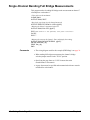
Single-Channel Bending Full Bridge Measurements . . . . .
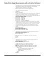
Relay Strain Gage Measurements with an External Voltmeter
FET Strain Gage Measurements with an External Voltmeter .
Measurements with Downloaded Unstrained References . . .
.
.
.
.
.
.
.
.
.
.
.
.
.
.
.
.
.
.
.
.
.
.
.
.
.
.
.
.
.
.
.
.
.
.
.
.
.
.
.
.
.
.
.
.
.
.
.
.
.
.
.
.
.
.
.
.
.
.
.
.
.
.
.
.
.
.
.
.
.
.
.
.
.
.
.
.
.
.
.
.
.
.
.
.
.
.
.
.
.
.
.
.
.
.
.
.
.
.
.
.
.
.
.
.
.
.
.
.
.
.
.
.
.
.
.
.
.
.
.
.
.
.
.
.
.
.
.
.
.
.
.
.
.
.
.
.
.
.
.
.
33
33
35
36
37
39
40
41
43
46
Chapter 4. Understanding the Strain Gage Multiplexers . . . . . . . . . . . . . . . . . . 49
About This Chapter . . . . . . . . . . . . . . . . . .
Making Strain Measurements . . . . . . . . . . . . .
Strain Measurement Procedure . . . . . . . . . .
Unbalanced Bridge Measurement Technique . .
Downloaded Unstrained References . . . . . . .
Strain Measurement Equations . . . . . . . . . .
Strain Gage Multiplexer Block Diagrams . . . . . . .
Block Diagram Description . . . . . . . . . . . .
Understanding the Strain Gage Measurement Circuits
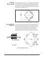
The Wheatstone Bridge . . . . . . . . . . . . . .
The Chevron Bridge . . . . . . . . . . . . . . .
The Wagner Ground . . . . . . . . . . . . . . .
Understanding the Bridge Configurations . . . . . . .
1/4 Bridge Measurements (QUARter) . . . . . .
1/2 Bridge Measurements . . . . . . . . . . . . .
Full Bridge Measurements . . . . . . . . . . . .
Measurements Using an External Voltmeter . . . . .
Set Up . . . . . . . . . . . . . . . . . . . . . . .
Procedure . . . . . . . . . . . . . . . . . . . . .
Voltage and Resistance Measurements . . . . . . . .
.
.
.
.
.
.
.
.
.
.
.
.
.
.
.
.
.
.
.
.
Chapter 5. Strain Gage Multiplexer Command Reference
About This Chapter . . . . . . .
Command Types . . . . . . . . .
Common Command Format
SCPI Command Format . .
Linking Commands . . . . .
SCPI Command Reference . . .
ABORt . . . . . . . . . . . . . .
ARM . . . . . . . . . . . . . . .
:COUNt . . . . . . . . . . .
:COUNt? . . . . . . . . . .
CALibration . . . . . . . . . . .
:STRain . . . . . . . . . . .
CONFigure . . . . . . . . . . . .
:STRain . . . . . . . . . . .
2
.
.
.
.
.
.
.
.
.
.
.
.
.
.
.
.
.
.
.
.
.
.
.
.
.
.
.
.
.
.
.
.
.
.
.
.
.
.
.
.
.
.
.
.
.
.
.
.
.
.
.
.
.
.
.
.
.
.
.
.
.
.
.
.
.
.
.
.
.
.
.
.
.
.
.
.
.
.
.
.
.
.
.
.
.
.
.
.
.
.
.
.
.
.
.
.
.
.
.
.
.
.
.
.
.
.
.
.
.
.
.
.
HP E1355A/56A/57A/58A Modules User’s Manual Contents
.
.
.
.
.
.
.
.
.
.
.
.
.
.
.
.
.
.
.
.
.
.
.
.
.
.
.
.
.
.
.
.
.
.
.
.
.
.
.
.
.
.
.
.
.
.
.
.
.
.
.
.
.
.
.
.
.
.
.
.
.
.
.
.
.
.
.
.
.
.
.
.
.
.
.
.
.
.
.
.
.
.
.
.
.
.
.
.
.
.
.
.
.
.
.
.
.
.
.
.
.
.
.
.
.
.
.
.
.
.
.
.
.
.
.
.
.
.
.
.
.
.
.
.
.
.
.
.
.
.
.
.
.
.
.
.
.
.
.
.
.
.
.
.
.
.
.
.
.
.
.
.
.
.
.
.
.
.
.
.
.
.
.
.
.
.
.
.
.
.
.
.
.
.
.
.
.
.
.
.
.
.
.
.
.
.
.
.
.
.
.
.
.
.
.
.
.
.
.
.
.
.
.
.
.
.
.
.
.
.
.
.
.
.
.
.
.
.
.
.
.
.
.
.
.
.
.
.
.
.
.
.
.
.
.
.
.
.
.
.
.
.
.
.
.
.
.
.
.
.
.
.
.
.
.
.
.
.
.
.
.
.
.
.
.
.
.
.
.
.
.
.
.
.
.
.
.
.
.
.
.
.
.
.
.
.
.
.
.
.
.
.
.
.
.
.
.
.
.
.
.
.
.
.
.
.
.
.
.
.
.
.
.
.
.
.
.
.
.
.
.
.
.
.
.
.
.
.
.
.
.
.
.
.
.
.
.
.
.
.
.
.
.
.
.
.
.
.
.
.
.
.
.
.
.
.
.
.
.
.
.
.
.
.
.
.
.
.
.
.
.
.
.
.
.
.
.
.
.
.
.
.
49
49
49
50
51
52
52
53
53
54
56
57
58
58
59
61
63
63
63
64
. . . . . . . . . . . . . . . . . 65
.
.
.
.
.
.
.
.
.
.
.
.
.
.
.
.
.
.
.
.
.
.
.
.
.
.
.
.
.
.
.
.
.
.
.
.
.
.
.
.
.
.
.
.
.
.
.
.
.
.
.
.
.
.
.
.
.
.
.
.
.
.
.
.
.
.
.
.
.
.
.
.
.
.
.
.
.
.
.
.
.
.
.
.
.
.
.
.
.
.
.
.
.
.
.
.
.
.
.
.
.
.
.
.
.
.
.
.
.
.
.
.
.
.
.
.
.
.
.
.
.
.
.
.
.
.
.
.
.
.
.
.
.
.
.
.
.
.
.
.
.
.
.
.
.
.
.
.
.
.
.
.
.
.
.
.
.
.
.
.
.
.
.
.
.
.
.
.
.
.
.
.
.
.
.
.
.
.
.
.
.
.
.
.
.
.
.
.
.
.
.
.
.
.
.
.
.
.
.
.
.
.
.
.
.
.
.
.
.
.
.
.
.
.
.
.
.
.
.
.
.
.
.
.
.
.
.
.
.
.
.
.
.
.
.
.
.
.
.
.
.
.
.
.
.
.
.
.
.
.
.
.
65
65
65
65
67
67
68
69
69
69
70
70
71
72
DISPlay . . . . . . . . . . . . .
:MONitor:CARD . . . . . .
:MONitor[:STATe] . . . . .
INITiate . . . . . . . . . . . . .
:CONTinuous . . . . . . . .
:CONTinuous? . . . . . . .
[:IMMediate] . . . . . . . .
MEASure . . . . . . . . . . . .
:STRain . . . . . . . . . . .
OUTPut . . . . . . . . . . . . .
[:STATe] . . . . . . . . . .
[:STATe]? . . . . . . . . . .
[ROUTe:] . . . . . . . . . . . .
CLOSe . . . . . . . . . . .
CLOSe? . . . . . . . . . . .
OPEN . . . . . . . . . . . .
OPEN? . . . . . . . . . . .
SCAN . . . . . . . . . . . .
SCAN:MODE . . . . . . . .
SCAN:MODE? . . . . . . .
SCAN:PORT . . . . . . . .
SCAN:PORT? . . . . . . .
SETTling[:TIME] . . . . . .
SETTling:TIME? . . . . . .
[SENSe:] . . . . . . . . . . . . .
STRain:GFACtor . . . . . .
STRain:GFACtor? . . . . .
STRain:POISson . . . . . .
STRain:POISson? . . . . . .
STRain:UNSTrained . . . .
STRain:UNSTrained? . . .
STATus . . . . . . . . . . . . .
:OPERation:ENABle . . . .
:OPERation[:EVENt]? . . .
SYSTem . . . . . . . . . . . . .
:CDEScription? . . . . . . .
:CPON . . . . . . . . . . .
:CTYPe? . . . . . . . . . .
:ERRor? . . . . . . . . . . .
TRIGger . . . . . . . . . . . . .
[:IMMediate] . . . . . . . .
:SOURce . . . . . . . . . .
:SOURce? . . . . . . . . . .
IEEE 488.2 Common Commands
Command Quick Reference . . .
.
.
.
.
.
.
.
.
.
.
.
.
.
.
.
.
.
.
.
.
.
.
.
.
.
.
.
.
.
.
.
.
.
.
.
.
.
.
.
.
.
.
.
.
.
.
.
.
.
.
.
.
.
.
.
.
.
.
.
.
.
.
.
.
.
.
.
.
.
.
.
.
.
.
.
.
.
.
.
.
.
.
.
.
.
.
.
.
.
.
.
.
.
.
.
.
.
.
.
.
.
.
.
.
.
.
.
.
.
.
.
.
.
.
.
.
.
.
.
.
.
.
.
.
.
.
.
.
.
.
.
.
.
.
.
.
.
.
.
.
.
.
.
.
.
.
.
.
.
.
.
.
.
.
.
.
.
.
.
.
.
.
.
.
.
.
.
.
.
.
.
.
.
.
.
.
.
.
.
.
.
.
.
.
.
.
.
.
.
.
.
.
.
.
.
.
.
.
.
.
.
.
.
.
.
.
.
.
.
.
.
.
.
.
.
.
.
.
.
.
.
.
.
.
.
.
.
.
.
.
.
.
.
.
.
.
.
.
.
.
.
.
.
.
.
.
.
.
.
.
.
.
.
.
.
.
.
.
.
.
.
.
.
.
.
.
.
.
.
.
.
.
.
.
.
.
.
.
.
.
.
.
.
.
.
.
.
.
.
.
.
.
.
.
.
.
.
.
.
.
.
.
.
.
.
.
.
.
.
.
.
.
.
.
.
.
.
.
.
.
.
.
.
.
.
.
.
.
.
.
.
.
.
.
.
.
.
.
.
.
.
.
.
.
.
.
.
.
.
.
.
.
.
.
.
.
.
.
.
.
.
.
.
.
.
.
.
.
.
.
.
.
.
.
.
.
.
.
.
.
.
.
.
.
.
.
.
.
.
.
.
.
.
.
.
.
.
.
.
.
.
.
.
.
.
.
.
.
.
.
.
.
.
.
.
.
.
.
.
.
.
.
.
.
.
.
.
.
.
.
.
.
.
.
.
.
.
.
.
.
.
.
.
.
.
.
.
.
.
.
.
.
.
.
.
.
.
.
.
.
.
.
.
.
.
.
.
.
.
.
.
.
.
.
.
.
.
.
.
.
.
.
.
.
.
.
.
.
.
.
.
.
.
.
.
.
.
.
.
.
.
.
.
.
.
.
.
.
.
.
.
.
.
.
.
.
.
.
.
.
.
.
.
.
.
.
.
.
.
.
.
.
.
.
.
.
.
.
.
.
.
.
.
.
.
.
.
.
.
.
.
.
.
.
.
.
.
.
.
.
.
.
.
.
.
.
.
.
.
.
.
.
.
.
.
.
.
.
.
.
.
.
.
.
.
.
.
.
.
.
.
.
.
.
.
.
.
.
.
.
.
.
.
.
.
.
.
.
.
.
.
.
.
.
.
.
.
.
.
.
.
.
.
.
.
.
.
.
.
.
.
.
.
.
.
.
.
.
.
.
.
.
.
.
.
.
.
.
.
.
.
.
.
.
.
.
.
.
.
.
.
.
.
.
.
.
.
.
.
.
.
.
.
.
.
.
.
.
.
.
.
.
.
.
.
.
.
.
.
.
.
.
.
.
.
.
.
.
.
.
.
.
.
.
.
.
.
.
.
.
.
.
.
.
.
.
.
.
.
.
.
.
.
.
.
.
.
.
.
.
.
.
.
.
.
.
.
.
.
.
.
.
.
.
.
.
.
.
.
.
.
.
.
.
.
.
.
.
.
.
.
.
.
.
.
.
.
.
.
.
.
.
.
.
.
.
.
.
.
.
.
.
.
.
.
.
.
.
.
.
.
.
.
.
.
.
.
.
.
.
.
.
.
.
.
.
.
.
.
.
.
.
.
.
.
.
.
.
.
.
.
.
.
.
.
.
.
.
.
.
.
.
.
.
.
.
.
.
.
.
.
.
.
.
.
.
.
.
.
.
.
.
.
.
.
.
.
.
.
.
.
.
.
.
.
.
.
.
.
.
.
.
.
.
.
.
.
.
.
.
.
.
.
.
.
.
.
.
.
.
.
.
.
.
.
.
.
.
.
.
.
.
.
.
.
.
.
.
.
.
.
.
.
.
.
.
.
.
.
.
.
.
.
.
.
.
.
.
.
.
.
.
.
.
.
.
.
.
.
.
.
.
.
.
.
.
.
.
.
.
.
.
.
.
.
.
.
.
.
.
.
.
.
.
.
.
.
.
.
.
.
.
.
.
.
.
.
.
.
.
.
.
.
.
.
.
.
.
.
.
.
.
.
.
.
.
.
.
.
.
.
.
.
.
.
.
.
.
.
.
.
.
.
.
.
.
.
.
.
.
.
.
.
.
.
.
.
.
.
.
.
.
.
.
.
.
.
.
.
.
.
.
.
.
.
.
.
.
.
.
.
.
.
.
.
.
.
.
.
.
.
.
.
.
.
.
.
.
.
.
.
.
.
.
.
.
.
.
.
.
.
.
.
.
.
.
.
.
.
.
.
.
.
.
.
.
.
.
.
.
.
.
.
.
.
.
.
.
.
.
.
.
.
.
.
.
.
.
.
.
.
.
.
.
.
.
.
.
.
.
.
.
.
.
.
.
.
.
.
.
.
.
.
.
.
.
.
.
.
.
.
.
.
.
.
.
.
.
.
.
.
.
.
.
.
.
.
.
.
.
.
.
.
.
.
.
.
.
.
.
.
.
.
.
.
.
.
.
.
.
.
.
.
.
.
.
.
.
.
.
.
.
.
.
.
.
.
.
.
.
.
.
.
.
.
.
.
.
.
.
.
.
.
.
.
.
.
.
.
.
.
.
.
.
.
.
.
.
.
.
.
.
.
.
.
.
.
.
.
.
.
.
.
.
.
.
.
.
.
.
.
.
.
.
.
.
.
.
.
.
.
.
.
.
.
.
.
.
.
.
.
.
.
.
.
.
.
.
.
.
.
.
.
.
.
.
.
.
.
.
.
.
.
.
.
73
73
74
75
75
76
76
77
78
79
79
79
80
80
81
82
82
83
85
85
86
86
87
87
88
88
89
89
89
90
90
91
91
91
92
92
93
93
94
95
95
95
97
98
99
HP E1355A/56A/57A/58A Modules User’s Manual Contents
3
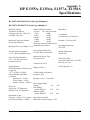
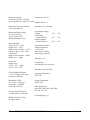
Appendix A. HP E1355A, E1356A, E1357A, E1358A Specifications . . . . . . . . . . . . 101
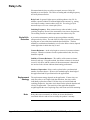
Relay Life . . . . . . . . . . . . . . . . . . . . . . . . . . . . . . . . . . . . . . . . . 103
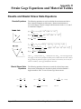
Appendix B. Strain Gage Equations and Material Tables . . . . . . . . . . . . . . . . . . 105
Rosette and Biaxial Stress State Equations . . . . . . . . . . . . . . . . . . . . . . . . 105
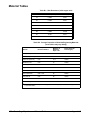
Material Tables . . . . . . . . . . . . . . . . . . . . . . . . . . . . . . . . . . . . . . 106
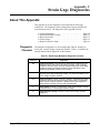
Appendix C. Strain Gage Diagnostics . . . . . . . . . . . . . . . . . . . . . . . . . . . . . 107
About This Appendix . . . . . . . . . . .
Diagnostic Channels . . . . . . . . .
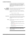
Leadwire Resistance . . . . . . . . . . . .
Leadwire Desensitization Corrections
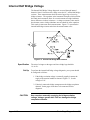
Internal Half Bridge Voltage . . . . . . .
Shunt Verification . . . . . . . . . . . . .
Guard Voltage . . . . . . . . . . . . . . .
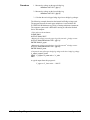
Bridge Excitation Voltage . . . . . . . . .
.
.
.
.
.
.
.
.
.
.
.
.
.
.
.
.
.
.
.
.
.
.
.
.
.
.
.
.
.
.
.
.
.
.
.
.
.
.
.
.
.
.
.
.
.
.
.
.
.
.
.
.
.
.
.
.
.
.
.
.
.
.
.
.
.
.
.
.
.
.
.
.
.
.
.
.
.
.
.
.
.
.
.
.
.
.
.
.
.
.
.
.
.
.
.
.
.
.
.
.
.
.
.
.
.
.
.
.
.
.
.
.
.
.
.
.
.
.
.
.
.
.
.
.
.
.
.
.
.
.
.
.
.
.
.
.
.
.
.
.
.
.
.
.
.
.
.
.
.
.
.
.
.
.
.
.
.
.
.
.
.
.
.
.
.
.
.
.
.
.
.
.
.
.
.
.
.
.
.
.
.
.
.
.
.
.
.
.
.
.
.
.
107
107
108
108
111
113
116
118
Appendix D. Strain Gage Register-Based Programming . . . . . . . . . . . . . . . . . . . 119
About This Appendix . . . . . . . . . . . . . . . . . . . . . . . . .
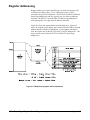
Register Addressing . . . . . . . . . . . . . . . . . . . . . . . . . .
The Base Address . . . . . . . . . . . . . . . . . . . . . . . . .
A16 Address Space Inside the Command Module or Mainframe
Register Offset . . . . . . . . . . . . . . . . . . . . . . . . . .
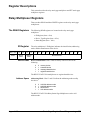
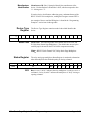
Register Descriptions . . . . . . . . . . . . . . . . . . . . . . . . .
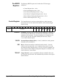
Relay Multiplexer Registers . . . . . . . . . . . . . . . . . . . . . .
The READ Registers . . . . . . . . . . . . . . . . . . . . . . .
ID Register . . . . . . . . . . . . . . . . . . . . . . . . . . . .
Device Type Register . . . . . . . . . . . . . . . . . . . . . . .
Status Register . . . . . . . . . . . . . . . . . . . . . . . . . .
The WRITE Registers . . . . . . . . . . . . . . . . . . . . . .
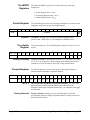
Control Register . . . . . . . . . . . . . . . . . . . . . . . . . .
Tree Switch Register . . . . . . . . . . . . . . . . . . . . . . .
Channel Register . . . . . . . . . . . . . . . . . . . . . . . . .
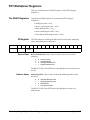
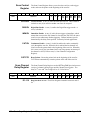
FET Multiplexer Registers . . . . . . . . . . . . . . . . . . . . . .
The READ Registers . . . . . . . . . . . . . . . . . . . . . . .
ID Register . . . . . . . . . . . . . . . . . . . . . . . . . . . .
Device Type Register . . . . . . . . . . . . . . . . . . . . . . .
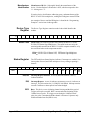
Status Register . . . . . . . . . . . . . . . . . . . . . . . . . .
Scan Control Register . . . . . . . . . . . . . . . . . . . . . . .
Scan Channel Delay Register . . . . . . . . . . . . . . . . . . .
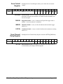
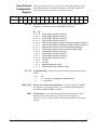
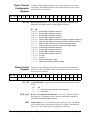
The WRITE Registers . . . . . . . . . . . . . . . . . . . . . .
Control Register . . . . . . . . . . . . . . . . . . . . . . . . . .
Scan Control Register . . . . . . . . . . . . . . . . . . . . . . .
Scan Channel Delay Register . . . . . . . . . . . . . . . . . . .
Scan Channel Configuration Register . . . . . . . . . . . . . .
Direct Channel Configuration Register . . . . . . . . . . . . . .
Direct Control Register . . . . . . . . . . . . . . . . . . . . . .
4
HP E1355A/56A/57A/58A Modules User’s Manual Contents
.
.
.
.
.
.
.
.
.
.
.
.
.
.
.
.
.
.
.
.
.
.
.
.
.
.
.
.
.
.
.
.
.
.
.
.
.
.
.
.
.
.
.
.
.
.
.
.
.
.
.
.
.
.
.
.
.
.
.
.
.
.
.
.
.
.
.
.
.
.
.
.
.
.
.
.
.
.
.
.
.
.
.
.
.
.
.
.
.
.
.
.
.
.
.
.
.
.
.
.
.
.
.
.
.
.
.
.
.
.
.
.
.
.
.
.
.
.
.
.
.
.
.
.
.
.
.
.
.
.
.
.
.
.
.
.
.
.
.
.
.
.
.
.
.
.
.
.
.
.
.
.
.
.
.
.
.
.
.
.
.
.
.
.
.
.
.
.
.
.
.
.
.
.
.
.
.
.
.
.
.
.
.
.
.
.
.
.
.
.
.
.
.
.
.
.
.
.
.
.
.
.
.
.
.
.
.
.
.
.
.
.
.
.
.
.
.
.
.
.
.
.
.
.
.
.
.
.
.
.
.
.
.
.
.
.
.
.
.
.
.
.
.
.
.
.
.
.
.
.
.
.
.
.
.
.
.
.
.
.
.
.
.
.
.
.
.
.
.
.
.
.
.
.
.
.
.
.
.
.
.
.
.
.
.
.
.
.
.
.
119
120
121
122
122
123
123
123
123
124
124
125
125
125
125
126
126
126
127
127
128
128
129
129
130
130
131
132
132
Programming Examples . . . . . . . . . . . .
Reading the ID Register . . . . . . . . .
Reading the Device Type Register . . . .
Resetting the Switchbox . . . . . . . . .
Measuring the Bridge Excitation Voltage
FET Multiplexer Scanning . . . . . . . .
.
.
.
.
.
.
.
.
.
.
.
.
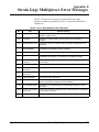
Appendix E. Strain Gage Multiplexer Error Messages
.
.
.
.
.
.
.
.
.
.
.
.
.
.
.
.
.
.
.
.
.
.
.
.
.
.
.
.
.
.
.
.
.
.
.
.
.
.
.
.
.
.
.
.
.
.
.
.
.
.
.
.
.
.
.
.
.
.
.
.
.
.
.
.
.
.
.
.
.
.
.
.
.
.
.
.
.
.
.
.
.
.
.
.
.
.
.
.
.
.
.
.
.
.
.
.
.
.
.
.
.
.
.
.
.
.
.
.
.
.
.
.
.
.
.
.
.
.
.
.
133
133
134
135
135
135
. . . . . . . . . . . . . . . . . . . 137
HP E1355A/56A/57A/58A Modules User’s Manual Contents
5
Notes
6
HP E1355A/56A/57A/58A Modules User’s Manual Contents
Certification
Hewlett-Packard Company certifies that this product met its published specifications at the time of shipment from the factory. HewlettPackard further certifies that its calibration measurements are traceable to the United States National Institute of Standards and Technology (formerly National Bureau of Standards), to the extent allowed by that organization’s calibration facility, and to the calibration
facilities of other International Standards Organization members.
Warranty
This Hewlett-Packard product is warranted against defects in materials and workmanship for a period of three years from date of shipment. Duration and conditions of warranty for this product may be superseded when the product is integrated into (becomes a part of)
other HP products. During the warranty period, Hewlett-Packard Company will, at its option, either repair or replace products which
prove to be defective.
For warranty service or repair, this product must be returned to a service facility designated by Hewlett-Packard (HP). Buyer shall prepay shipping charges to HP and HP shall pay shipping charges to return the product to Buyer. However, Buyer shall pay all shipping
charges, duties, and taxes for products returned to HP from another country.
HP warrants that its software and firmware designated by HP for use with a product will execute its programming instructions when
properly installed on that product. HP does not warrant that the operation of the product, or software, or firmware will be uninterrupted
or error free.
Limitation Of Warranty
The foregoing warranty shall not apply to defects resulting from improper or inadequate maintenance by Buyer, Buyer-supplied products or interfacing, unauthorized modification or misuse, operation outside of the environmental specifications for the product, or improper site preparation or maintenance.
The design and implementation of any circuit on this product is the sole responsibility of the Buyer. HP does not warrant the Buyer’s
circuitry or malfunctions of HP products that result from the Buyer’s circuitry. In addition, HP does not warrant any damage that occurs as a result of the Buyer’s circuit or any defects that result from Buyer-supplied products.
NO OTHER WARRANTY IS EXPRESSED OR IMPLIED. HP SPECIFICALLY DISCLAIMS THE IMPLIED WARRANTIES OF
MERCHANTABILITY AND FITNESS FOR A PARTICULAR PURPOSE.
Exclusive Remedies
THE REMEDIES PROVIDED HEREIN ARE BUYER’S SOLE AND EXCLUSIVE REMEDIES. HP SHALL NOT BE LIABLE
FOR ANY DIRECT, INDIRECT, SPECIAL, INCIDENTAL, OR CONSEQUENTIAL DAMAGES, WHETHER BASED ON CONTRACT, TORT, OR ANY OTHER LEGAL THEORY.
Notice
The information contained in this document is subject to change without notice. HEWLETT-PACKARD (HP) MAKES NO WARRANTY OF ANY KIND WITH REGARD TO THIS MATERIAL, INCLUDING, BUT NOT LIMITED TO, THE IMPLIED WARRANTIES OF MERCHANTABILITY AND FITNESS FOR A PARTICULAR PURPOSE. HP shall not be liable for errors contained
herein or for incidental or consequential damages in connection with the furnishing, performance or use of this material. This document contains proprietary information which is protected by copyright. All rights are reserved. No part of this document may be photocopied, reproduced, or translated to another language without the prior written consent of Hewlett-Packard Company. HP assumes no
responsibility for the use or reliability of its software on equipment that is not furnished by HP.
Restricted Rights Legend
Use, duplication or disclosure by the U.S. Government is subject to restrictions as set forth in subparagraph (c)(1)(ii) of the Rights in
Technical Data and Computer Software clause in DFARS 252.227-7013.
Hewlett-Packard Company
3000 Hanover Street
Palo Alto, California 94304 U.S.A.
Rights for non-DOD U.S. Government Departments and Agencies are as set forth in FAR 52.227-19 (c) (1,2).
HP E1355A/56A/57A/58A Strain Gage Multiplexer Module User’s Manual
Edition 3
Copyright © 1995 Hewlett-Packard Company. All Rights Reserved.
HP E1355A/56A/57A/58A Strain Gage Multiplexer Module User’s Manual
7
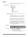
Documentation History
All Editions and Updates of this manual and their creation date are listed below. The first Edition of the manual is Edition 1. The Edition number increments by 1 whenever the manual is revised. Updates, which are issued between Editions, contain replacement pages
to correct or add additional information to the current Edition of the manual. Whenever a new Edition is created, it will contain all of
the Update information for the previous Edition. Each new Edition or Update also includes a revised copy of this documentation history page.
Edition 1 . . . . . . . . . . . . . . . . . . . . . . . . . . . . . . . . . . . . . . . . . . . . . . August 1990
Edition 2 . . . . . . . . . . . . . . . . . . . . . . . . . . . . . . . . . . . . . . . . . . . . . October 1993
Edition 3 . . . . . . . . . . . . . . . . . . . . . . . . . . . . . . . . . . . . . . . . . . . . . . August 1995
Safety Symbols
Instruction manual symbol affixed to product. Indicates that the user must refer to the
manual for specific WARNING or CAUTION information to avoid personal injury
or damage to the product.
Alternating current (AC).
Direct current (DC).
Indicates hazardous voltages.
Indicates the field wiring terminal that must
be connected to earth ground before operating the equipment—protects against electrical shock in case of fault.
or
Frame or chassis ground terminal—typically connects to the equipment’s metal
frame.
WARNING
Calls attention to a procedure, practice, or
condition that could cause bodily injury or
death.
CAUTION
Calls attention to a procedure, practice, or condition that could possibly cause damage to
equipment or permanent loss of data.
WARNINGS
The following general safety precautions must be observed during all phases of operation, service, and repair of this product.
Failure to comply with these precautions or with specific warnings elsewhere in this manual violates safety standards of design,
manufacture, and intended use of the product. Hewlett-Packard Company assumes no liability for the customer’s failure to
comply with these requirements.
Ground the equipment: For Safety Class 1 equipment (equipment having a protective earth terminal), an uninterruptible safety earth
ground must be provided from the mains power source to the product input wiring terminals or supplied power cable.
DO NOT operate the product in an explosive atmosphere or in the presence of flammable gases or fumes.
For continued protection against fire, replace the line fuse(s) only with fuse(s) of the same voltage and current rating and type.
DO NOT use repaired fuses or short-circuited fuse holders.
Keep away from live circuits: Operating personnel must not remove equipment covers or shields. Procedures involving the removal
of covers or shields are for use by service-trained personnel only. Under certain conditions, dangerous voltages may exist even with the
equipment switched off. To avoid dangerous electrical shock, DO NOT perform procedures involving cover or shield removal unless
you are qualified to do so.
DO NOT operate damaged equipment: Whenever it is possible that the safety protection features built into this product have been impaired, either through physical damage, excessive moisture, or any other reason, REMOVE POWER and do not use the product until
safe operation can be verified by service-trained personnel. If necessary, return the product to a Hewlett-Packard Sales and Service Office for service and repair to ensure that safety features are maintained.
DO NOT service or adjust alone: Do not attempt internal service or adjustment unless another person, capable of rendering first aid
and resuscitation, is present.
DO NOT substitute parts or modify equipment: Because of the danger of introducing additional hazards, do not install substitute
parts or perform any unauthorized modification to the product. Return the product to a Hewlett-Packard Sales and Service Office for
service and repair to ensure that safety features are maintained.
8
HP E1355A/56A/57A/58A Strain Gage Multiplexer Module User’s Manual
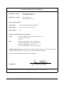
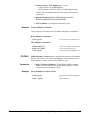
Declaration of Conformity
according to ISO/IEC Guide 22 and EN 45014
Manufacturer’s Name:
Hewlett-Packard Company
Loveland Manufacturing Center
Manufacturer’s Address:
815 14th Street S.W.
Loveland, Colorado 80537
declares, that the product:
Product Name:
8-Channel Strain Gage Multiplexer Module
Model Number:
E1355A, E1356A, E1357A, E1358A
Product Options:
All
conforms to the following Product Specifications:
Safety:
IEC 1010-1 (1990) Incl. Amend 1 (1992)/EN61010-1 (1993)
CSA C22.2 #1010.1 (1992)
UL 1244
EMC:
CISPR 11:1990/EN55011 (1991): Group1 Class A
IEC 801-2:1991/EN50082-1 (1992): 4kVCD, 8kVAD
IEC 801-3:1984/EN50082-1 (1992): 3 V/m
IEC 801-4:1988/EN50082-1 (1992): 1kV Power Line
Supplementary Information: The product herewith complies with the requirements of the Low Voltage Directive
73/23/EEC and the EMC Directive 89/336/EEC and carries the CE-marking accordingly.
Tested in a typical configuration in an HP B-Size VXI mainframe.
July 20, 1995
Jim White, QA Manager
European contact: Your local Hewlett-Packard Sales and Service Office or Hewlett-Packard GmbH, Department
HQ-TRE, Herrenberger Straße 130, D-71034 Böblingen, Germany (FAX +49-7031-14-3143).
HP E1355A/56A/57A/58A Strain Gage Multiplexer Module User’s Manual
9
Notes
10
HP E1355A/56A/57A/58A Strain Gage Multiplexer Module User’s Manual
Please fold and tape for mailing
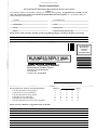
Reader Comment Sheet
HP E1355A/56A/57A/58A Strain Gage Multiplexer Module User’s Manual
Edition 3
You can help us improve our manuals by sharing your comments and suggestions. In appreciation of your time, we will
enter you in a quarterly drawing for a Hewlett-Packard Palmtop Personal Computer (U.S. government employees
cannot participate in the drawing).
Your Name
City, State/Province
Company Name
Country
Job Title
Zip/Postal Code
Address
Telephone Number with Area Code
Please list the system controller, operating system, programming language, and plug-in modules you are using.
fold here
cut along this line
NO POSTAGE
NECESSARY
IF MAILED
IN THE
UNITED STATES
BUSINESS REPLY MAIL
FIRST CLASS
PERMIT NO. 37
LOVELAND, CO
HEWLETT-PACKARD COMPANY
Measurement Systems Division
Learning Products Department
P.O. Box 301
Loveland, CO 80539-9984
fold here
Please pencil-in one circle for each statement below:
• The documentation is well organized.
• Instructions are easy to understand.
• The documentation is clearly written.
• Examples are clear and useful.
• Illustrations are clear and helpful.
• The documentation meets my overall expectations.
Please write any comments or suggestions below--be specific.
Disagree
O
O
O
O
O
O
O
O
O
O
O
O
O
O
O
O
O
O
O
O
O
O
O
O
Agree
O
O
O
O
O
O
12
HP E1355A/56A/57A/58A Strain Gage Multiplexer Module User’s Manual
Chapter 1
Getting Started with the Strain Gage
Multiplexers
About This Chapter
This chapter describes the physical and functional characteristics of the HP
E1355A, E1356A, E1357A, and E1358A Strain Gage Multiplexers; and
explains how the multiplexers are prepared for use in a VXIbus system.
The sections of this chapter are:
• Strain Gage Multiplexer Overview . . . . . . . . . . . . . . . . . . . . Page 13
• Using the Multiplexers in a VXIbus System . . . . . . . . . . . . . Page 14
Strain Gage Multiplexer Overview
The strain gage multiplexers, together with the HP E1326B/E1411B
Multimeter, provide static and dynamic strain measurement capabilities for
an HP Series B or Series C VXIbus system.
Physical
Description
The HP E1355A and E1356A are B-size, 8-channel, 120Ω and 350Ω
RELAY Strain Gage Multiplexers, respectively. The HP E1355A and
E1356A terminal modules use the HP E1345-66201 component assembly.
The relay multiplexers use a single B-size or C-size mainframe slot.
The HP E1357A and E1358A are B-Size, 8-channel, 120Ω and 350Ω FET
Strain Gage Multiplexers, respectively. The E1357A and E1358A terminal
modules use the HP E1351-66201 component assembly. The FET
multiplexers also use a single B-size or C-size mainframe slot.
Functional
Description
The measurement capabilities of the relay and FET strain gage multiplexers
include the following:
• 1⁄4 Bridge Measurements
- 8 Channels
- Rosettes
• 1⁄2 Bridge Measurements
- 8 Channels
- Bending 1⁄2 Bridge
- Poisson 1⁄2 Bridge
Chapter 1
Getting Started with the Strain Gage Multiplexers
13
• Full Bridge Measurements
- 8 Channels
- Bending Full Bridge
- Bending Poisson Full Bridge
- Poisson Full Bridge
• Guarded DCV Voltage and 2-wire Resistance Measurements
- 8 Channels
- Allowed with strain measurements on adjacent channels
• Diagnostics
- Leadwire Resistance (channels 0 and 1)
- Internal Half Bridge Voltage
- Shunt Verification (E1355A and E1356A only)
- Guard Voltage
- Bridge Excitation Voltage
Strain measurement examples are found in Chapter 3. The diagnostics are
covered in Appendix C.
Note
The electrical characteristics and strain measurement circuitry used by the
strain gage multiplexers are covered in Chapter 4.
Using the Multiplexers in a VXIbus System
This section prepares the strain gage multiplexers for use in a VXIbus
system.
Identifying the
Terminal Module
Relay Multiplexers
Note
14
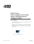
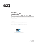
The card ID jumpers and card ID switch (Figure 1-1) indicates which
terminal assembly is used. Since the HP E1345-66201 and HP
E1351-66201 assemblies are used with a variety of terminal modules, the
ID jumpers or ID switch may need to be changed. To reduce setup time and
avoid configuration errors, check the jumper or switch setting to make sure
they match the terminal module used.
When the relay strain gage multiplexers are shipped from the factory, the card
ID jumpers are set according to the terminal module (E1355A/E1356A)
shipped with them (Figure 1-1). The system is able to identify the multiplexer
with or without the terminal module attached.
If the jumper setting does not match the terminal module attached, the
system will identify the card based on the jumper setting.
Getting Started with the Strain Gage Multiplexers
Chapter 1
FET Multiplexers
Note
When the FET strain gage multiplexers are shipped from the factory, the
card ID switches are set to the "OPEN" (0) position (Figure 1-1). The
terminal module is identified when the module is plugged onto the
component assembly and when the mainframe is turned on.
When the terminal card is not attached, the system identifies the multiplexer
as an HP E1351A 16-channel FET multiplexer when the card ID switches
are in the OPEN (0) position.
Figure 1-1. Checking the Card ID Jumper/Switch
Chapter 1
Getting Started with the Strain Gage Multiplexers
15
Setting the Card ID
Switch
Note
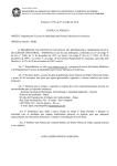
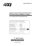
In certain applications it may be necessary for the system to identify the
FET strain gage multiplexer without the terminal card attached. Figure 1-2
shows the card ID switch settings which identify the HP E1357A and HP
E1358A FET Strain Gage Multiplexers.
Make certain the card ID switch setting matches the terminal card used. If
they do not match, a configuration error may occur or the wrong terminal
card may be identified.
Figure 1-2. Identifying the HP E1357A/E1358A
16
Getting Started with the Strain Gage Multiplexers
Chapter 1
Selecting the
Interrupt Line
Number
The multiplexer’s IRQ jumper/switch (Figure 1-3) selects one of seven
interrupt lines used to communicate with the system’s Slot 0 module.
In a scanning multimeter configuration (see “Strain Gage Multiplexer
Configurations” on page 19), the multiplexer’s (relay and FET) do not use
an interrupt line since communication is between the multimeter and the
Slot 0 module.
In a switchbox configuration, the multiplexers use an interrupt line. At the
factory, the IRQ jumper (or switch) is set to line 1. Since the system
instrument in the Series B mainframe is assigned to each line and the Series
C command module (E1406A) is assigned line 1 by default, it is not
necessary to change the IRQ jumper/switch setting. If the command
module in Series C systems is assigned another line and the switchbox is to
use that line, the IRQ jumper/switch must be set accordingly.
Figure 1-3. The IRQ Jumper/Switch
Chapter 1
Getting Started with the Strain Gage Multiplexers
17
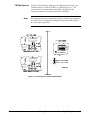
Internally Supplied
Bridge Excitation
Voltage
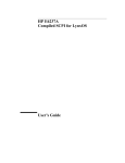
A feature of the strain gage multiplexer is the availability of an internally
supplied bridge excitation voltage. This voltage, which drives the
multiplexer’s Wheatstone Bridge strain measurement circuitry (Chapter 4),
is capable of driving eight channels of full bridge measurements.
Figure 1-4. Internally Supplied Bridge Excitation Voltage
Relay Multiplexer
Excitation Voltage
CAUTION
The internal bridge excitation voltage for the HP E1355A/E1356A relay
strain gage multiplexers is +5V, fused at 4A. This voltage is accessed by
installing jumpers on the component assembly as indicated in Figure 1-4.
Note, however, that this signal may not be stable enough or pure enough for
some strain measurements.
If jumpers are installed and then the +5V Bridge Excitation is
shorted, the main fuse on the PC board may blow and reset the
mainframe. This would set all instruments in the mainframe to
their power-on state. To increase protection, install a one amp
fuse (HP part number 2110-0665) in place of the wire short.
When the relay multiplexers are shipped from the factory, the jumpers are
not installed. Thus, the excitation voltage must be externally supplied as
explained in Chapter 2.
18
Getting Started with the Strain Gage Multiplexers
Chapter 1
FET Multiplexer
Excitation Voltage
The internal bridge excitation voltage for the HP E1357A/E1358A FET
strain gage multiplexers is +4.6V referenced to mainframe chassis, and
current limited at 450 mA. The voltage is accessed as indicated by the
(movable) jumper setting shown in Figure 1-4.
When the FET multiplexers are shipped from the factory, the jumper is in
the "ON" position. If the jumper is moved to the "OFF" position, the
excitation voltage must be externally supplied as explained in Chapter 2.
CAUTION
Strain Gage
Multiplexer
Configurations
If the bridge excitation voltage is externally supplied, be sure
that the jumper is not installed, or with the FET multiplexers,
ensure that the "STRAIN EXCITATION" jumper is in the "OFF"
position. Otherwise, unpredictable strain measurements may
result.
In a B-Size or C-Size VXIbus system, the strain gage multiplexers can be
used in two configurations:
• Scanning Multimeter
(multiplexers are used with an HP E1326B/E1411B Multimeter)
• Switchbox
(multiplexers are used with an external voltmeter)
Guidelines for creating a scanning multimeter and switchbox follow.
Creating a Scanning
Multimeter Instrument
In a scanning multimeter instrument, signals measured by the HP
E1326B/E1411B Multimeter are input via the multiplexer channels.
Channel openings and closings are controlled by the multimeter through
commands sent to the multimeter. To create a scanning multimeter
instrument:
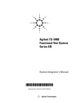
• The instrument must have one module (the multimeter) assigned as
the instrument identifier. The instrument identifier is the module
with a logical address that is a multiple of 8 (8, 16, 24, …). The HP
E1326B/E1411B Multimeter has a factory set logical address of 24.
• The modules in the scanning multimeter instrument must have
successive logical addresses, beginning with the logical address of the
multimeter. For example, with a multimeter logical address of 24, the
logical addresses of the multiplexers must be 25, 26, and so on.
• The strain gage multiplexers have a factory set logical address of
112. The logical address is changed using the logical address
switches shown in Figure 1-5.
Chapter 1
Getting Started with the Strain Gage Multiplexers
19
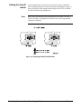
Creating a Switchbox
Instrument
In a switchbox instrument, signals are routed (switched) to a voltmeter
external to the HP 75000 Series B or Series C mainframe. Multiplexer
channel openings and closings are controlled by the user through commands
sent directly to the switchbox. A switchbox instrument is created as follows:
• The instrument must have one module (multiplexer) assigned as the
instrument identifier. The instrument identifier is the module with a
logical address that is a multiple of 8 (8, 16, 24, …).
• The multiplexers in the switchbox instrument must have successive
logical addresses, beginning with the logical address of the
instrument identifier. For example, the multiplexers in a switchbox
might have logical addresses of 112, 113, 114, and so on.
• All strain gage multiplexers have a factory set logical address of 112.
The logical address is changed using the logical address switches
shown in Figure 1-5.
Note
Detailed information on creating virtual instruments in a VXIbus system
can be found in the HP 75000 Series B Installation and Getting Started
Guide, or in the HP E1406A Command Module User’s Manual.
Figure 1-5. Creating a Scanning Multimeter and a Switchbox
20
Getting Started with the Strain Gage Multiplexers
Chapter 1
Instrument
Addressing
Instruments in an HP 75000 Series B or Series C mainframe are located
with an HP-IB address. The HP-IB address is a combination of the
computer’s interface select code, the primary HP-IB address of the
mainframe’s system instrument, and the secondary HP-IB address of the
virtual instrument. Addresses of this form in an HP BASIC statement might
appear as:
OUTPUT 70903;"...
OUTPUT 70914;"...
Interface Select Code (7): Determined by the address of the HP-IB
interface card in the computer. In most Hewlett-Packard computers, this
card has a factory set address of 7.
Primary HP-IB Address (09): This is the address of the HP-IB port on the
Series B mainframe and on the Series C HP E1406A Command Module.
The mainframe and command module have a factory set address of 9.
Secondary HP-IB Address (03) (14): This address is determined by
dividing the logical address of the instrument identifier by 8. Thus, for a
scanning multimeter with an instrument identifier logical address of 24, the
secondary address is 03. For a switchbox with an instrument identifier
logical address of 112, the secondary address is 14.
Multiplexer Card
Numbers
The multiplexer modules in a scanning multimeter and switchbox
instrument assume card numbers within the instrument (Figure 1-4). The
multiplexer with the lowest logical address is card number 1, the next
lowest logical address is card number 2, and so on. Thus, in the following
configurations, the multiplexer card numbers would be:
Scanning Multimeter
Logical address = 24
Logical address = 25
Logical address = 26
Logical address = 27
(multimeter)
(multiplexer - card number 1)
(multiplexer - card number 2)
(multiplexer - card number 3)
Switchbox
Logical address = 112
Logical address = 113
Logical address = 114
Logical address = 115
Chapter 1
(multiplexer - card number 1)
(multiplexer - card number 2)
(multiplexer - card number 3)
(multiplexer - card number 4)
Getting Started with the Strain Gage Multiplexers
21
Multiplexer Channel
Addresses
The strain gage multiplexer channels within the scanning multimeter and
switchbox are specified in the form:
(@ccnn)
(@ccnn,ccnn)
(@ccnn:ccnn)
(@ccnn:ccnn,ccnn:ccnn)
- single channel
- multiple channels
- sequential channels
- groups of sequential channels
where "cc" is the card number and "nn" is the channel number. For
example:
(@100:107)
specifies channels 0 through 7 on (multiplexer) card number 1. The leading 0
in the card number can be omitted.
Chapter 3 contains example programs showing how a channel (and channel
list) is specified in a strain measurement command. The strain measurement
commands are described in detail in Chapter 5.
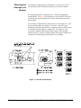
Connecting the
Multiplexers
In scanning multimeter and switchbox instruments, the multiplexers are
connected to the multimeter and to other multiplexers with an analog bus
cable, or with an analog bus cable and a digital bus cable (Figure 1-6). The
cables used are determined as follows:
1. If the scanning multimeter or switchbox uses relay (strain gage)
multiplexers only, the analog bus cable is used.
2. If the scanning multimeter or switchbox uses FET (strain gage)
multiplexers only, the analog bus cable and the digital bus cable
are used.
3. If the scanning multimeter or switchbox uses a combination of relay
and FET multiplexers, only the analog bus cable is used.
Figure 1-6. Connecting the Analog and Digital Bus Cables
Descriptions of the analog bus and digital bus cables are found in the
HP E1326B/E1411B Multimeter Manual.
22
Getting Started with the Strain Gage Multiplexers
Chapter 1
Chapter 2
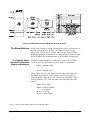
Connecting Strain Gages to the Multiplexers
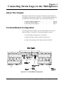
About This Chapter
This chapter explains how the strain gage multiplexer terminal module is
configured for measurements, and how 1⁄4, 1⁄2, and full bridge configurations
are connected to the terminal module. The sections of this chapter are:
• Terminal Module Configuration . . . . . . . . . . . . . . . . . . . . . . Page 23
• Wiring a Terminal Module . . . . . . . . . . . . . . . . . . . . . . . . . . Page 26
• Strain Gage Wiring Diagrams . . . . . . . . . . . . . . . . . . . . . . . . Page 27
Terminal Module Configuration
The strain gage terminal module used with each multiplexer accessory is
shown in Figures 2-1A and 2-1B. The terminal module is used to:
• select the bridge arrangement on each channel;
• supply the bridge excitation voltage (external source);
• connect the strain gages to the bridge completion channels.
Figure 2-1A. Terminal Module Configuration
Chapter 2
Connecting Strain Gages to the Multiplexers
23
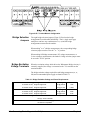
Figure 2-1B. Terminal Module Configuration
Bridge Selection
Jumpers
The eight bridge selection jumpers (Figure 2-1B) select the bridge
arrangement for each channel individually. Thus, a single strain gage
multiplexer can have any combination of 1⁄4, 1⁄2, and full bridge
arrangements connected to the module.
When making 1⁄4 or 1⁄2 bridge measurements, the corresponding bridge
selection jumper must be set to the "1⁄4 - 1⁄2" position.
When making full bridge measurements, DC voltage measurements, or
2-wire resistance measurements, the channel’s bridge selection jumper must
be set to the "FULL" position.
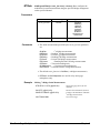
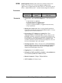
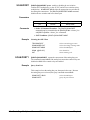
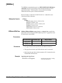
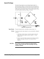
Bridge Excitation
Voltage Terminals
When the excitation voltage which drives the Wheatstone Bridge circuitry is
externally supplied, the voltage is connected to the "Vs" terminals on the
terminal module.
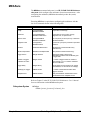
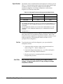
The bridge excitation voltage required for each bridge arrangement (1⁄4, 1⁄2,
full) and a recommended power supply are found in Table 2-1.
Table 2-1. Bridge Excitation Voltage and Power Requirements
1⁄4
or 1⁄2 Bridge Arrangements
Voltage
Power
8 channels of 120Ω bridge arrangements
5V @ 200 mA
1.0W
8 channels of 350Ω bridge arrangements
5V @ 70 mA
0.35W
Full Bridge Arrangements
Voltage
Power
8 channels of 120Ω bridge arrangements
5V @ 400 mA
2.0W
8 channels of 350Ω bridge arrangements
5V @140 mA
0.7W
PARD (periodic and random deviation from DC value):
1 mVp-p 20 Hz to 20 MHz
Recommended Power Supply:
HP 6414C or equivalent
24
Connecting Strain Gages to the Multiplexers
Chapter 2
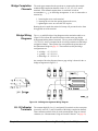
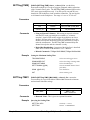
Bridge Completion
Channels
The strain gages mounted to the specimen are connected to the terminal
module bridge completion channels via the +E, -E1, -E2, H, L, and G
terminals. Each channel contains these six terminals in order to
accommodate a 1⁄4, 1⁄2, or full bridge arrangement. A wire is connected to a
terminal by:
1. loosening the screw on the terminal,
2. inserting the wire into the opening opposite the screw,
3. tightening the screw to secure the wire in place.
Routing the wires under the strain relief clamp will prevent the wires from
being pulled out of the terminal.
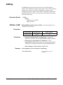
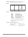
Bridge Wiring
Diagrams
The 1⁄4, 1⁄2, and full bridge wiring diagrams on the terminal module cover
(Figure 2-1B) indicate the connections between the strain gage bridge
arrangement and the channel terminals. The six points on the diagrams: +E,
-E1, -E2, H, L, and G correspond to the six wiring terminals on each bridge
completion channel. These points also correspond to the points shown on
the Wheatstone Bridge on page 54. The terminals used by the bridge
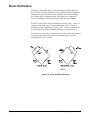
configurations are:
• 1⁄4 bridge - +E -E1 H G
• 1⁄2 bridge - +E -E2 H G
• full bridge- +E -E2 H L G
An example of how the diagram relates to gage wiring is shown for the 1⁄4
bridge arrangement in Figure 2-2.
Figure 2-2. 1/4 Bridge Arrangement Wiring Diagram
H L G Voltmeter
Terminals
Chapter 2
The common high (H), low (L), and guard (G) terminals are the same point
electrically as the H, L, and G terminals of the bridge completion channels.
These common terminals allow for strain measurements using an external
voltmeter (see “ Measurements Using an External Voltmeter” on page 63).
Connecting Strain Gages to the Multiplexers
25
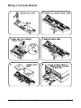
Wiring a Terminal Module
26
Connecting Strain Gages to the Multiplexers
Chapter 2
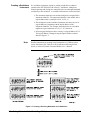
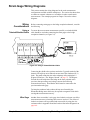
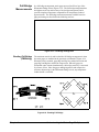
Strain Gage Wiring Diagrams
This section contains the wiring diagrams for the strain measurement
configurations available with the multiplexers. The section also shows how
to connect an external voltmeter to a switchbox in order to make strain
measurements. The example programs in Chapter 3 also refer to these
diagrams.
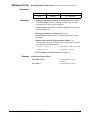
Wiring
Considerations
Using a
Twisted-Shielded Cable
Before connecting strain gages to the bridge completion channels, consider
the following.
To ensure the most accurate measurements possible, a twisted-shielded
cable should be used when connecting the strain gages to the bridge
completion channels (see Figure 2-3).
Figure 2-3. Using a Twisted-Shielded Cable
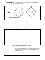
Connecting the shield to the specimen and to the G (guard) terminal of the
channel will help keep noise induced currents out of the conductor (H, L)
leads. The guard connection also takes advantage of the multiplexer’s
Wagner Ground (see “ The Wagner Ground” on page 57). The Wagner
Ground drives the midpoint of the bridge to the same potential as the
specimen, thus preventing stray leakage currents from affecting
measurement accuracy. Note that the shield must be connected to the
specimen and not the gage.
Twisting the conductor leads reduces the loop area formed by the
Wheatstone Bridge arms which may be exposed to magnetic fields which
can degrade measurement accuracy.
Wire Gage
Chapter 2
Another factor to consider is wire gage since leadwire resistance can affect
measurement accuracy when long cable runs are involved. The effects of
leadwire resistance can be predicted and corrected for by using the wire
resistance table in Appendix B and the Leadwire Resistance Diagnostic on
page 108.
Connecting Strain Gages to the Multiplexers
27
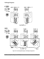
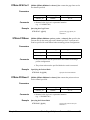
1/4 Bridge Diagrams
Figure 2-4. Connecting Strain Gages in 1/4 Bridge Arrangements
28
Connecting Strain Gages to the Multiplexers
Chapter 2
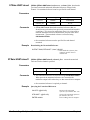
1/2 Bridge Diagrams
Figure 2-5. Connecting Strain Gages in 1/2 Bridge Arrangements
Chapter 2
Connecting Strain Gages to the Multiplexers
29
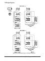
Full Bridge
Diagrams
Figure 2-6. Connecting Strain Gages in Full Bridge Arrangements
30
Connecting Strain Gages to the Multiplexers
Chapter 2
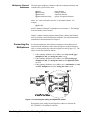
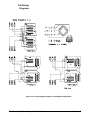
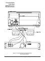
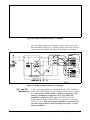
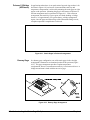
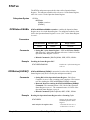
Connecting Relay
Strain Gage
Multiplexers to an
External Voltmeter
Figure 2-7. Connecting Relay Strain Gage Multiplexers
to an External Voltmeter
Chapter 2
Connecting Strain Gages to the Multiplexers
31
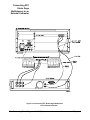
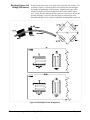
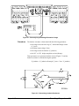
Connecting FET
Strain Gage
Multiplexers to an
External Voltmeter
Figure 2-8. Connecting FET Strain Gage Multiplexers
to an External Voltmeter
32
Connecting Strain Gages to the Multiplexers
Chapter 2
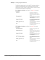
Chapter 3
Making Strain Gage Measurements
About This Chapter
This chapter contains example programs which make strain gage
measurements with various bridge configurations. The examples in this
chapter include:
•
•
•
•
•
Single-Channel 1⁄4 Bridge Measurements . . . . . . . . . . . . . . .
Multi-Channel 1⁄4 Bridge Measurements. . . . . . . . . . . . . . . .
Dynamic Strain Measurements . . . . . . . . . . . . . . . . . . . . . . .
Rosette Measurements . . . . . . . . . . . . . . . . . . . . . . . . . . . . . .
Single-Channel Bending Full Bridge
Measurement. . . . . . . . . . . . . . . . . . . . . . . . . . . . . . . . . .
• Relay Strain Gage Measurements with an External
Voltmeter . . . . . . . . . . . . . . . . . . . . . . . . . . . . . . . . . . . .
• FET Strain Gage Measurements with an External
Voltmeter . . . . . . . . . . . . . . . . . . . . . . . . . . . . . . . . . . . .
• Measurements with Downloaded Unstrained
References. . . . . . . . . . . . . . . . . . . . . . . . . . . . . . . . . . . .
r
Using the Example
Prog ams
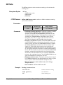
Programming
Language
Page 35
Page 36
Page 37
Page 39
Page 40
Page 41
Page 43
Page 46
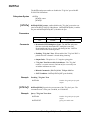
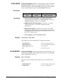
The purpose of the chapter is to provide example programs that show you
how to make strain gage measurements, and to provide programs that can be
used directly in your applications.
The example programs are shown in the HP BASIC language and assume
the multimeter is controlled from an HP 9000 Series 300 computer over the
HP-IB.
When using HP BASIC, a command is sent to the scanning multimeter
instrument with the OUTPUT statement:
OUTPUT 70903;"MEAS:STR:QUAR? (@100)"
The destination specified (70903) is the interface select code of the
computer (7), plus the HP-IB addresses of the HP 75000 Series B
mainframe or Series C command module (09), plus the multimeter
instrument address (03). The multimeter command is enclosed between
quotation marks.
Data from the multimeter instrument is entered into the computer using the
ENTER statement:
ENTER 70903;variable
Chapter 3
Making Strain Gage Measurements
33
Note
Connecting Strain
Gages
Strain Measurement
Procedure
Except as noted, each program in this chapter assumes the strain gage
multiplexer (relay and FET) is used with the HP E1326B/E1411B
multimeter as part of a scanning multimeter instrument at secondary HP-IB
address 03.
Chapter 2 contains the wiring diagrams for connecting strain gages to the
multiplexer bridge completion channels. Each example program indicates
the wiring diagram used.
Strain measurements with the strain gage multiplexers and HP E1326B/
E1411B multimeter are made as follows:
1. Specify the Gage Factor and, for Poisson configurations, the Poisson
Ratio.
2. Measure the unstrained reference voltage (Vout/Vs) unstrained.
3. Add tension to the specimen.
4. Configure the multimeter and make the strain measurement
(Vout/Vs) strained.
Each example in this chapter uses this procedure. Chapter 4 covers the
procedure in detail.
34
Making Strain Gage Measurements
Chapter 3
Single-Channel 1/4 Bridge Measurements
This program makes a 1⁄4 bridge strain measurement on channel 0 of
multiplexer card number 1.
!Clear and reset the multimeter.
CLEAR 70903
OUTPUT 70903;"*RST"
!Specify the gage factor for the channel measured.
OUTPUT 70903;"STR:GFAC 2.11E-6,(@100)"
!Measure the channel’s unstrained reference.
OUTPUT 70903;"CAL:STR (@100)"
DISP "Add tension to the specimen; then press ’Continue’"
PAUSE
DISP ""
!Measure the strain on the channel. Enter and display the reading.
OUTPUT 70903;"MEAS:STR:QUAR? (@100)"
ENTER 70903;Strn_rdg
PRINT Strn_rdg
END
Comments
• The wiring diagram used for this example is on page 28.
• Specifying the gage factor as 2.11E-6 returns the strain measurement
in microstrain.
• A gage factor must be specified and an unstrained reference must be
measured for each channel.
Chapter 3
Making Strain Gage Measurements
35
Multi-Channel 1/4 Bridge Measurements
This program makes 1⁄4 bridge strain measurements on channels 0, 1, and 2
of multiplexer card number 1.
!Dimension a computer variable to store the strain measurements.
DIM Strn_rdgs(1:3)
!Clear and reset the multimeter.
CLEAR 70903
OUTPUT 70903;"*RST"
!Specify the gage factor for each channel measured.
OUTPUT 70903;"STR:GFAC 2.11E-6,(@100:102)"
!Measure the unstrained reference for each channel.
OUTPUT 70903;"CAL:STR (@100:102)"
DISP "Add tension to the specimen; then press ’Continue’"
PAUSE
DISP ""
!Measure the strain on the specified channels. Enter and display the readings.
OUTPUT 70903;"MEAS:STR:QUAR? (@100:102)"
ENTER 70903;Strn_rdgs(*)
PRINT Strn_rdgs(*)
END
Comments
• The wiring diagram used for this example is on page 28.
• Specifying the gage factor as 2.11E-6 returns the strain
measurements in microstrain.
• A gage factor must be specified and an unstrained reference must be
measured for each channel.
36
Making Strain Gage Measurements
Chapter 3
Dynamic Strain Measurements
This program makes 2,000 1⁄4 bridge strain measurements over a period of
one second. The measurements are made on channel 0 of multiplexer card
number 1.
!Dimension computer variables to store the data header and readings. Assign
!an input/output path between the multimeter and computer. This is a path for
!data in the REAL 64 format. Clear the path and reset the multimeter.
DIM Ndig$[1],Count$[9],Strn_rdgs(1:2000)
ASSIGN @Dmm TO 70903;FORMAT OFF
CLEAR @Dmm
OUTPUT 70903;"*RST"
!Specify the gage factor for the channel measured.
OUTPUT 70903;"STR:GFAC 2.11E-6,(@100)"
!Measure the channel’s unstrained reference.
OUTPUT 70903;"CAL:STR (@100)"
DISP "Add tension to the specimen; then press ’Continue’"
PAUSE
DISP ""
!To increase throughput speed, specify the multimeter’s REAL 64 data format
!and turn off the mainframe display. Configure the multimeter for 1⁄4 bridge
!strain measurements on channel 0. To achieve 2000 measurements in 1
!second, specify a fixed (lowest) range, set the aperture time to accept the
!necessary sample period, turn autozero off, specify the number of
!measurements to be taken, and specify the source of the sample signal and the
!sample period.
OUTPUT 70903;"FORM REAL,64"
OUTPUT 70903;"DISP:MON OFF"
OUTPUT 70903;"CONF:STR:QUAR (@100)"
OUTPUT 70903;" VOLT:RANG MIN"
OUTPUT 70903;" VOLT:APER 100E-6"
OUTPUT 70903;" CAL:ZERO:AUTO OFF"
OUTPUT 70903;" SAMP:COUN 2000"
OUTPUT 70903;" SAMP:SOUR TIM"
OUTPUT 70903;" SAMP:TIM 500E-6"
!Measure the strain on the specified channel.
OUTPUT 70903;"INIT"
OUTPUT 70903;"FETC?"
!Enter and display the readings.
ENTER @Dmm USING "#,X,K,K";Ndig$;Count$[1;VAL(Ndig$)]
ENTER @Dmm;Strn_rdgs(*)
ENTER @Dmm
PRINT Strn_rdgs(*)
END
Chapter 3
Making Strain Gage Measurements
37
Comments
• The wiring diagram used for this example is on page 28.
• Specifying the gage factor as 2.11E-6 returns the strain
measurements in microstrain.
• A gage factor must be specified and an unstrained reference must be
measured for each channel.
• The REAL,64 format is selected because the HP 9000 Series
200/300 computer stores readings in that format.
• REAL,64 data is transferred to the computer in the IEEE 488.2-1987
Definite Length Arbitrary Block format. Data in this format is
preceded by a header consisting of: # <non-zero digit> <block
length>. In this program, the header preceding the measurement
data is #516000. The 5 represents the number of digits indicating the
block length (16000), and 16000 is the block length (2,000 readings
* 8 bytes/reading).
• When HP BASIC is used, the program’s ENTER @Dmm USING…
statement is used to remove the Arbitrary Block header:
# - tells the computer not to terminate the ENTER until all
ENTER statements have completed.
X - tells the computer to skip the first character of the Arbitrary
Block header (#).
K,K - stores the <non-zero digit> and <block length> portions
of the header in the Ndig$ and Count$ variables respectively.
• The ENTER @Dmm;Rdgs(*) statement enters the readings into the
computer. Since a Line Feed (LF) follows the last reading, ENTER
@Dmm removes the LF character from the multimeter output buffer.
If the LF character is not removed, error -410 "Query Interrupted"
occurs the next time data is sent to the buffer. This (third) ENTER
statement is only required when using the REAL data formats.
38
Making Strain Gage Measurements
Chapter 3
Rosette Measurements
This program makes a rectangular rosette measurement on channels 0, 1,
and 2 of multiplexer card number 1.
!Dimension a computer variable to store the strain measurements.
DIM Strn_rdgs(1:3)
!Clear and reset the multimeter.
CLEAR 70903
OUTPUT 70903;"*RST"
!Specify the gage factor for each channel measured.
OUTPUT 70903;"STR:GFAC 2.075E-6,(100,102);:GFAC 2.11E-6,(@101)"
!Measure the unstrained reference for each channel.
OUTPUT 70903;"CAL:STR (@100:102)"
DISP "Add tension to the specimen; then press ’Continue’"
PAUSE
DISP ""
!Measure the strain on the specified channels. Enter and display the readings.
OUTPUT 70903;"MEAS:STR:QUAR? (@100:102)"
ENTER 70903;Strn_rdgs(*)
E1=Strn_rdgs(1)
E2=Strn_rdgs(2)
E3=Strn_rdgs(3)
Epsilon=.5*(E1+E3+((E1-E3)^2+(2*E2-E1-E3)^2)^.5)
Sigma=(10.4/2)*((E1+E3)/(1-.32)+1/(1+.32)*((E1-E3)^2+(2*E2-E1-E3)^2)^.5)
Theta=.5*ATN((2*E2-E1-E3)/(E1-E3))
PRINT Epsilon
PRINT Sigma
PRINT Theta
END
Comments
• The wiring diagram used for this example is on page 28.
• A gage factor must be specified, and an unstrained reference must be
measured for each channel.
• A rosette measurement is a series of three 1⁄4 bridge measurements
(channels 100 - 102). Each measurement is substituted into the
applicable equation.
• The rosette equations used in this program are listed in Appendix B.
For this program, a poisson ratio (ν) of 0.32 and modulus of
elasticity (E) of 10.4 are assumed.
Chapter 3
Making Strain Gage Measurements
39
Single-Channel Bending Full Bridge Measurements
This program makes a bending full bridge strain measurement on channel 7
of multiplexer card number 1.
!Clear and reset the multimeter.
CLEAR 70903
OUTPUT 70903;"*RST"
!Specify the gage factor for the channel measured.
OUTPUT 70903;"STR:GFAC 2.115E-6,(@107)"
!Measure the channel’s unstrained reference.
OUTPUT 70903;"CAL:STR (@107)"
DISP "Add tension to the specimen; then press ’Continue’"
PAUSE
DISP ""
!Measure the strain on the channel. Enter and display the reading.
OUTPUT 70903;"MEAS:STR:FBEN? (@107)"
ENTER 70903;Strn_rdg
PRINT Strn_rdg
END
Comments
• The wiring diagram used for this example (FBENding) is on page 30.
• When making full bridge measurements, the channel’s bridge
selection jumper must be in the "FULL" position.
• Specifying the gage factor as 2.115E-6 returns the strain
measurements in microstrain.
• A gage factor must be specified and an unstrained reference must be
measured for each channel.
40
Making Strain Gage Measurements
Chapter 3
Relay Strain Gage Measurements with an External Voltmeter
This program shows how strain measurements are made using a relay strain
gage multiplexer switchbox and an external (HP 3458A) voltmeter.
!Dimension computer variables to store the readings.
DIM Vout_unstr(1:3),Vout_str(1:3),Vr(1:3),Epsilon(1:3)
!Clear and reset the external multimeter.
CLEAR 722
OUTPUT 722;"RESET"
!Configure the external multimeter for DC voltage measurements. Configure its
!trigger system such that the multimeter is externally triggered (when the
!multiplexer channel is closed), and so that it outputs a trigger signal when the
!measurement is complete (to trigger the multiplexer).
OUTPUT 722;"PRESET NORM"
OUTPUT 722;" MEM FIFO"
OUTPUT 722;" TBUFF ON"
OUTPUT 722;" TRIG EXT"
OUTPUT 722;" EXTOUT RCOMP,NEG"
!Configure the relay multiplexer switchbox so that it outputs a trigger signal
!(via the mainframe “Trig Out” port) when a channel is closed, and so that it is
!externally triggered (via the mainframe “Event In” port) to close a channel.
!Connect the analog bus, which carries the bridge output and excitation
!voltages, to the HI, LO, and Guard terminals on the multiplexer terminal
!module.
OUTPUT 70914;"*RST"
OUTPUT 70914;"OUTP ON"
OUTPUT 70914;"TRIG:SOUR EXT"
OUTPUT 70914;"SCAN:PORT ABUS"
!Download the scan list to measure Vout and Vs unstrained. Close the first
!channel in the list to start the scan.
OUTPUT 70914;"SCAN (@100:102,115)"
OUTPUT 70914;"INIT"
DISP "Add tension to the specimen; then press ’Continue’"
PAUSE
DISP ""
!Download the scan list to measure Vout and Vs strained. Close the first
!channel in the list to start the scan.
OUTPUT 70914;"SCAN (@100:102,115)"
OUTPUT 70914;"INIT"
!Compute and display the 1/4 bridge strain measurements.
ENTER 722;Vout_unstr(*),Vs_unstr,Vout_str(*),Vs_str
CALL Strn_cmput(Vr(*),Vout_str(*),Vout_unstr(*),Vs_str,Vs_unstr)
END
SUB Strn_cmput(Vr(*),Vout_str(*),Vout_unstr(*),Vs_str,Vs_unstr)
FOR I=1 TO 3
Vr(I)=Vout_str(I)/Vs_str-Vout_unstr(I)/Vs_unstr
Epsilon(I)=-4*Vr(I)/2.11E-6*(1+2*Vr(I))
PRINT Epsilon(I)
NEXT I
SUBEND
Chapter 3
Making Strain Gage Measurements
41
Comments
• The strain gage wiring diagram used for this example is on page 28.
The diagram showing how the HP 3458A Multimeter is connected to
the relay strain gage multiplexer (via the mainframe) is on page 31.
• When making strain measurements with an external voltmeter, the
following voltages are measured in the sequence shown:
bridge output voltage (Vout: channels 100 - 102) unstrained
bridge excitation voltage (Vs: channel 115) unstrained
bridge output voltage (Vout: channels 100 - 102) strained
bridge excitation voltage (Vs: channel 115) strained
These measurements are used to compute Vr, which in equation
form is defined as:
Vr = [(Vout/Vs)strained - (Vout/Vs)unstrained]
Vr is then substituted into the equation (Table 4-1) for 1⁄4 bridge
measurements.
• The HP E1300/E1301 mainframe’s "Event In" and "Trig Out" ports are
connected to the voltmeter’s "VM Compl" and "Ext Trig" ports,
respectively. Thus, when a multiplexer channel is closed, a "channel
closed" pulse from the mainframe’s "Trig Out" port is applied to the
voltmeter’s "Ext Trig" port. When the voltmeter measurement is
complete, the voltmeter complete signal is applied to the "Event In" port
which triggers the multiplexer to close the next channel in the list.
42
Making Strain Gage Measurements
Chapter 3
FET Strain Gage Measurements with an External Voltmeter
This program shows how strain measurements are made using a FET strain
gage multiplexer switchbox and an external (HP 3458A) voltmeter.
!Dimension a computer variables to store the readings.
DIM Vout_unstr(1:3),Vout_str(1:3),Vr(1:3),Epsilon(1:3)
!Clear and reset the external multimeter.
CLEAR 722
OUTPUT 722;"RESET"
!Configure the external multimeter for DC voltage measurements. Configure its
!trigger system such that the multimeter is externally triggered (when the
!multiplexer channel is closed), and so that it outputs a trigger signal when the
!measurement is complete (to trigger the multiplexer).
OUTPUT 722;"PRESET NORM"
OUTPUT 722;" MEM FIFO"
OUTPUT 722;" TBUFF ON"
OUTPUT 722;" TRIG EXT"
OUTPUT 722;" EXTOUT RCOMP,NEG"
!Configure the FET multiplexer switchbox so that a channel is closed when a
!trigger is received via the digital bus. Close the multiplexer tree relays
!necessary to make a DC voltage measurement. Connect the analog bus, which
!carries the bridge output and excitation voltages, to the HI, LO, and Guard
!terminals on the multiplexer terminal module. Set a delay between when the
!trigger to close a channel is received, and when the channel closed trigger is
!generated. This prevents voltmeter triggers from occurring too fast.
OUTPUT 70914;"*RST"
OUTPUT 70914;"TRIG:SOUR:DBUS"
OUTPUT 70914;"SCAN:MODE VOLT"
OUTPUT 70914;"SCAN:PORT ABUS"
OUTPUT 70914;"SETT:TIM MAX,(@100)"
!Download the scan list to measure Vout and Vs unstrained.
OUTPUT 70914;"SCAN (@100:102,115)"
OUTPUT 70914;"INIT"
DISP "Add tension to the specimen; then press ’Continue’"
PAUSE
DISP ""
!Download the scan list to measure Vout and Vs strained.
OUTPUT 70914;"SCAN (@100:102,115)"
OUTPUT 70914;"INIT"
!Compute and display the 1 ⁄4 bridge strain measurements.
ENTER 722;Vout_unstr(*),Vs_unstr,Vout_str(*),Vs_str
CALL Strn_cmput(Vr(*),Vout_str(*),Vout_unstr(*),Vs_str,Vs_unstr)
END
SUB Strn_cmput(Vr(*),Vout_str(*),Vout_unstr(*),Vs_str,Vs_unstr)
FOR I=1 TO 3
Vr(I)=Vout_str(I)/Vs_str-Vout_unstr(I)/Vs_unstr
Epsilon(I)=-4*Vr(I)/2.11E-6*(1+2*Vr(I))
PRINT Epsilon(I)
NEXT I
SUBEND
Chapter 3
Making Strain Gage Measurements
43
Comments
• The strain gage wiring diagram used for this example is on page 28.
The diagram showing how the HP 3458A Multimeter is connected to
the FET strain gage multiplexer is on page 32.
• When making strain measurements with an external voltmeter, the
following voltages are measured in the sequence shown:
bridge output voltage (Vout: channels 100 - 102) unstrained
bridge excitation voltage (Vs: channel 115) unstrained
bridge output voltage (Vout: channels 100 - 102) strained
bridge excitation voltage (Vs: channel 115) strained
These measurements are used to compute Vr, which in equation
form is defined as:
Vr = [(Vout/Vs)strained - (Vout/Vs)unstrained]
Vr is then substituted into the equation (Table 4-1 on page 52) for
1⁄4 bridge measurements.
• The channel closed/measurement handshake sequence between the
FET multiplexer switchbox and the voltmeter occurs over the
multiplexer’s digital bus. When connected as shown in Figure 2-8,
the digital bus cable (HP Part Number E1411-80001) connects the
multiplexer’s "channel advance" and "channel closed" pins to the
voltmeter’s "VM Compl" and "Ext Trig" ports, respectively. Thus,
when a multiplexer channel is closed, a "channel closed" pulse from
the multiplexer is applied to the voltmeter’s "Ext Trig" port. When
the voltmeter measurement is complete, the voltmeter complete
signal triggers the multiplexer via the "channel advance" line.
Continued on Next Page
44
Making Strain Gage Measurements
Chapter 3
• The FET multiplexer switchbox can be used with an external
voltmeter without using the digital bus cable. Connect the voltmeter
to the switchbox as indicated in Figure 2-7 on page 31. However, do
not connect the cable between the voltmeter’s "voltmeter
complete" port and the mainframe’s "Event In" port. Modify
the previous program as follows:
!Configure the external multimeter for DC voltage measurements. Configure its
!trigger system such that the multimeter is externally triggered (when the
!multiplexer channel is closed).
OUTPUT 722;"PRESET NORM"
OUTPUT 722;" MEM FIFO"
OUTPUT 722;" TBUFF ON"
OUTPUT 722;" TRIG EXT"
!Configure the FET multiplexer switchbox so that it outputs a trigger pulse
!when a channel is closed. Set the switchbox to be triggered by the *TRG
!command. Close the multiplexer tree relays necessary to make DC voltage
!measurements. Connect the analog bus, which carries the bridge output and
!excitation voltages, to the HI, LO, and Guard terminals on the multiplexer
!terminal module.
OUTPUT 70914;"*RST"
OUTPUT 70914;"OUTP ON"
OUTPUT 70914;"TRIG:SOUR:BUS"
OUTPUT 70914;"SCAN:MODE VOLT"
OUTPUT 70914;"SCAN:PORT ABUS"
!Measure Vout and Vs unstrained. INIT closes the first channel in the list.
!(*TRG) is used to advance and complete the scan. The WAIT statements allow
!the voltmeter measurement to complete before the next channel is closed.
OUTPUT 70914;"SCAN (@100:102,115)"
OUTPUT 70914;"INIT"
WAIT .1
FOR I=1 TO 4
OUTPUT 70914;"*TRG"
WAIT .1
NEXT I
DISP "Add tension to the specimen; then press ’Continue’"
PAUSE
DISP ""
!Measure Vout and Vs strained. Again, INIT closes the first channel in the list.
!Backplane triggers (*TRG) are issued to advance and complete the scan. The
!WAIT statements allow the voltmeter measurement to complete before the next
!channel is closed.
OUTPUT 70914;"SCAN (@100:102,115)"
OUTPUT 70914;"INIT"
WAIT .1
FOR I=1 TO 4
OUTPUT 70914;"*TRG"
WAIT .1
NEXT I
This modification allows the multimeter to be triggered when a multiplexer
channel is closed. However, the multiplexer is triggered by the user (*TRG)
which advances the scan.
Chapter 3
Making Strain Gage Measurements
45
Measurements with Downloaded Unstrained References
In certain applications, it may not be possible to measure unstrained
references ((Vout/Vs)unstrained) prior to making the actual strain
measurements. A feature of the strain gage multiplexers is the ability to
measure unstrained references, store the references in a computer, and then
download them at the time the strain measurements are made.
The following example shows how unstrained references are measured,
stored in a computer, and then downloaded when the strain measurements
are made.
!Dimension computer variables to store the unstrained reference measurements
!and strain measurements.
DIM Unstr(0:2),Strn_rdgs(0:2)
!Clear and reset the multimeter.
CLEAR 70903
OUTPUT 70903;"*RST"
!With the specimen in an unstrained state, call the subprogram which measures
!the unstrained references for each channel. Store the references in a computer
!variable.
CALL Ref_meas(Unstr(*))
!Once the specimen is in a strained state, the strain measurements can be made.
PAUSE
!Make three sets of strain measurements. For each set, specify the gage factor,
!download the unstrained references and then measure the strain. Enter and
!display the readings.
OUTPUT 70903;"STR:GFAC 2.11E-6,(@100:102)"
CALL Ref_load(Unstr(*))
FOR J=1 TO 5
OUTPUT 70903;"MEAS:STR:QUAR? (@100:102)"
ENTER 70903;Strn_rdgs(*)
PRINT Strn_rdgs(*)
NEXT J
PRINT
WAIT 5
OUTPUT 70903;"STR:GFAC 2.11E-6,(@100:102)"
CALL Ref_load(Unstr(*))
FOR J=1 TO 5
OUTPUT 70903;"MEAS:STR:QUAR? (@100:102)"
ENTER 70903;Strn_rdgs(*)
PRINT Strn_rdgs(*)
NEXT J
PRINT
WAIT 5
Continued on Next Page
46
Making Strain Gage Measurements
Chapter 3
OUTPUT 70903;"STR:GFAC 2.11E-6,(@100:102)"
CALL Ref_load(Unstr(*))
FOR J=1 TO 5
OUTPUT 70903;"MEAS:STR:QUAR? (@100:102)"
ENTER 70903;Strn_rdgs(*)
PRINT Strn_rdgs(*)
NEXT J
END
!This subprogram measures the unstrained references, queries the references,
!and then stores the references in a computer variable for later use.
SUB Ref_meas(Unstr(*))
OUTPUT 70903;"CAL:STR (@100:102)"
OUTPUT 70903;"STR:UNST? (@100:102)"
ENTER 70903;Unstr(*)
SUBEND
!This subprogram downloads the unstrained references prior to the strain
!measurements.
SUB Ref_load(Unstr(*))
FOR I=0 TO 2
OUTPUT 70903;"STR:UNST ";Unstr(I);",(@";100+I;")"
NEXT I
SUBEND
Comments
• This program makes 1⁄4 bridge measurements on channels 0, 1, and 2 of
multiplexer card number 1. The wiring diagram used is on page 28.
• Since each strain measurement must have an unstrained reference,
the unstrained references are downloaded prior to each set of
measurements.
• The unstrained references can be stored on disk for later use.
Chapter 3
Making Strain Gage Measurements
47
Notes
48
Making Strain Gage Measurements
Chapter 3
Chapter 4
Understanding the Strain Gage Multiplexers
About This Chapter
This chapter describes the strain measurement procedure used by the
examples in Chapter 3, and also describes the measurement circuitry
associated with 1⁄4, 1⁄2, and full bridge measurements. The sections of this
chapter are:
• Making Strain Measurements . . . . . . . . . . . . . . . . . . . . . . . . Page 49
• Strain Gage Multiplexer Block Diagrams . . . . . . . . . . . . . . . Page 52
• Understanding the Strain Gage Measurement
Circuits . . . . . . . . . . . . . . . . . . . . . . . . . . . . . . . . . . . . . . Page 53
• Understanding the Bridge Configurations . . . . . . . . . . . . . . . Page 58
• Measurements Using an External Voltmeter. . . . . . . . . . . . . Page 63
• Voltage and Resistance Measurements . . . . . . . . . . . . . . . . . Page 64
Making Strain Measurements
This section explains the procedure used to make strain measurements.
Also covered are the equations (in the instrument firmware) which calculate
the measured strain.
Strain
Measurement
Procedure
The procedure for making strain measurements with the HP E1355A E1358A Strain Gage Multiplexers and HP E1326B/E1411B Multimeter is:
1. Specify the Gage Factor and, for Poisson configurations, the Poisson
Ratio.
STRain:GFACtor gage_factor,(@channel_list)
STRain:POISson poisson_ratio,(@channel_list)
One gage_factor and poisson_ratio (Poisson configurations) must be
specified for each channel.
2. Measure the unstrained reference voltage.
CALibration:STRain (@channel_list)
One unstrained reference voltage measurement must be made on
each channel. Note that this command leaves the HP
E1326B/E1411B Multimeter configured for an unstrained reference
voltage measurement. The multimeter must be reconfigured to make
the strain measurement (Step 4).
Chapter 4
Understanding the Strain Gage Multiplexers
49
The unstrained reference measurement is made because of the
unbalanced bridge method of strain measurement. Instead of
balancing (nulling) the bridge before each measurement, an
unstrained reference ((Vout/Vs)unstrained) is measured for each
channel. The unbalanced bridge measurement technique is described
in the next section.
3. Add tension to the specimen.
4. Configure the multimeter and make the strain measurement(s).
MEASure:STRain:strain_function? (@channel_list)
or
CONFigure:STRain:strain_function,(@channel_list)
When MEASure is used, the multimeter is configured and the
measurement is immediately taken. Because of this, variations to the
multimeter configuration (range, aperture time) are limited to the
values set by the MEASure command (see the table on page 77).
When CONFigure is used, the multimeter is configured but the
measurement is not taken until READ? or INIT is executed. Thus,
low-level multimeter commands (covered in the multimeter manual)
can be used to change the configuration (range, aperture time) before
the measurement is made.
Note
Unbalanced Bridge
Measurement
Technique
50
The strain measurement commands identified in this procedure are HP
E1326B/E1411B Multimeter commands. Information on how these
commands relate to strain measurements and how the multimeter makes
strain measurements is contained in this manual. Information on the entire
multimeter command set and on general multimeter operation is contained
in the HP E1326B/E1411B User’s Manual.
The strain gage multiplexers measure strain using an unbalanced
Wheatstone Bridge (see “ Understanding the Strain Gage Measurement
Circuits” on page 53). Unbalanced bridge measurement techniques do not
require the bridge to be balanced (manually or electronically) before strain
measurements are made.
Understanding the Strain Gage Multiplexers
Chapter 4
Calculating Vr
Residing in the instrument firmware are the equations used to calculate the
measured strain (Table 4-1 on page 52). One parameter common to each
equation is Vr. Vr is the difference in ratios of the Wheatstone Bridge
output voltage (Vout) to the bridge excitation voltage (Vs), under strained
and unstrained conditions. In equation form, Vr is represented as:
Vr = [(Vout/Vs)strained - (Vout/Vs)unstrained]
The strain measurement procedure involves measuring the voltages which
determine Vr. Once Vr is known, the firmware calculates the value of strain.
When CALibration:STRain (@channel_list) is executed, the multimeter
measures the unstrained bridge output voltage (Vout) and the bridge
excitation voltage (Vs), and computes the unstrained reference (Vout/Vs)
for each channel.
When MEASure:STRain:strain_function? (@channel list) is executed, the
multimeter measures the strained bridge output voltage (Vout) and the
bridge excitation voltage (Vs). The ratio of Vout/Vs(strained) is calculated
for each channel and is used with the channel’s unstrained reference to
determine Vr.
Note
Downloaded
Unstrained
References
Vs unstrained and Vs strained is measured one time per channel list. If the
channel list includes more than one multiplexer, Vs is measured one time on
each multiplexer.
The strain gage multiplexers have the capability of measuring the unstrained
reference voltages, storing the references in a computer, and then
downloading the references at the time the strain measurements are made.
This feature is useful in applications where repeated strain measurements
are made once a single unstrained reference has been measured. The
commands to measure, store, and download the unstrained reference are:
CALibration:STRain (@channel_list)
(measures the unstrained reference)
STRain:UNSTrained? (@channel_list)
(queries the references and returns them to the output buffer from where
they are entered into the computer)
STRain:UNSTrained reference,(@channel_list)
(downloads the unstrained references)
An example of how unstrained references are downloaded is found on page 46.
Chapter 4
Understanding the Strain Gage Multiplexers
51
Strain
Measurement
Equations
The equations in the instrument firmware which calculate the measured
strain are given in Table 4-1.
Table 4-1. Strain Measurement Equations
Arrangement
1⁄4
Bridge
Bending 1⁄2 Bridge
Poisson 1⁄2 Bridge
Bending Full Bridge
Bending Poisson Full Bridge
Poisson Full Bridge
Equation
ε = -4Vr/GF(1 + 2Vr)
ε = -2Vr/GF
ε = -4Vr/GF[(1 + ν)-2Vr(ν −1)]
ε = -Vr/GF
ε = -2Vr/GF(ν + 1)
ε = -2Vr/GF[(ν + 1) -Vr(ν −1)]
Parameter
QUARter
HBENding
HPOisson
FBENding
FBPoisson
FPOisson
ε = strain. For results in microstrain, multiply the calculated (measured)
strain by 1E-6.
NOTE: tensile strain is (+), compressive strain is (-)
Vr = [(Vout/VS)strained - (Vout/VS) unstrained]
Vout = bridge output voltage
Vs = bridge excitation voltage
GF = Gage Factor
ν = Poisson Ratio
Strain Gage Multiplexer Block Diagrams
The manner in which strain-related signals are routed from the specimen to
the multimeter is illustrated with the block diagrams in Figure 4-1.
Figure 4-1. Strain Gage Multiplexer Block Diagrams
52
Understanding the Strain Gage Multiplexers
Chapter 4
Block Diagram
Description
For all strain measurements, the bridge configuration is wired from the
specimen to selected +E, -EI , -E2, H, L, and G terminals on the strain gage
multiplexer terminal module.
When a strain (measurement) command is executed, the bridge completion
channel’s relay or FET switch is closed, as is the multiplexer’s tree relay or
tree switch. This passes the H, L, and G signals from the strain gage to the
multimeter, via the analog bus. The +E, -E1, and -E2 signals are wired
directly to the strain gage measurement circuitry on the terminal module.
The measurement circuitry is covered in the following sections.
Understanding the Strain Gage Measurement Circuits
This section describes the strain gage measurement circuits used by each
strain gage multiplexer. These circuits include:
• Wheatstone Bridge
• Chevron Bridge
• Wagner Ground
Chapter 4
Understanding the Strain Gage Multiplexers
53
The Wheatstone
Bridge
The Wheatstone Bridge Circuit shown in Figure 4-2 is the fundamental
strain measuring circuit.
Figure 4-2. The Wheatstone Bridge
When a strain gage is wired to a bridge completion channel, it completes the
Wheatstone Bridge circuit as indicated in Figure 4-3. This circuit represents
a 1⁄4 bridge arrangement where only one arm contains an active element
(strain gage). The other arms are fixed value resistors (as shown) or they
may represent unstrained gages.
Figure 4-3. Bridge Completion Circuitry - 1/4 Bridge
In a 1⁄2 bridge arrangement, the 120Ω or 350Ω bridge completion resistor is
replaced by a strain gage when the gages are connected to the terminals as
indicated in Figure 4-4.
54
Understanding the Strain Gage Multiplexers
Chapter 4
Figure 4-4. Bridge Completion Circuitry - 1/2 Bridge
For a full bridge arrangement, strain gages comprise all four arms of the
Wheatstone Bridge (Figure 4-5). Note the position of the bridge selection
jumper required to configure the channel for full bridge measurements.
Figure 4-5. Bridge Completion Circuitry - Full Bridge
120Ω and 350Ω
Multiplexers
Chapter 4
A 120Ω strain gage multiplexer is distinguished from a 350Ω multiplexer
by the value of the Wheatstone bridge completion resistor shown in Figure
4-3. When strain is measured with a 1⁄4 bridge arrangement, a 120Ω
strain gage multiplexer is required for 120Ω gages, and a 350Ω
multiplexer is required for 350Ω gages. In the 1⁄2 and full bridge
arrangements, the bridge completion resistor is replaced by a strain gage
(Figures 4-4, 4-5). Thus, any strain gage multiplexer can be used with
any value of gage resistance when measuring strain with a 1⁄2 or full
bridge arrangement.
Understanding the Strain Gage Multiplexers
55
The Chevron Bridge
When measuring strain with 1⁄4 and 1⁄2 bridge arrangements, the strain gage
accessories use a variation of the Wheatstone Bridge known as the Chevron
Bridge (Figure 4-6). The 1⁄4 bridge and 1⁄2 bridge arrangements still
complete the Wheatstone Bridge; however, the Chevron Bridge enables the
bridge excitation voltage (VS) and the precision internal half bridge
resistors (R1/R2) of the bridge completion circuitry to be shared among all
channels.
Because the multiplexers use an unbalanced bridge for strain measurements
(see “ Unbalanced Bridge Measurement Technique” on page 50), the
accuracy of the measurement depends on the resistance of the bridge arms
remaining constant. The resistance must remain constant for the unstrained
measurement and the strain measurement. The only resistance which
changes is the resistance of the active gage(s).
MULTIMETER
(VIA ANALOG BUS)
Figure 4-6. The Chevron Bridge
The Chevron Bridge ensures that the bridge arm resistance remains constant
by switching the outputs of the bridge completion channels (HI (high), LO
(low), G (guard)) to the input of the multimeter. By switching the outputs
rather than switching the bridge arms, the gages are "permanently" wired to
the bridge completion channels via the +E, -E1, and -E2 terminals. This
eliminates any resistance changes due to self heating and variations in
switch or relay contact resistance.
Note
56
G (guard) is not switched on the FET multiplexers.
Understanding the Strain Gage Multiplexers
Chapter 4
The Wagner Ground
To increase measurement accuracy, the relay strain gage multiplexers
contain a Wagner Ground circuit similar to that shown in Figure 4-7. The
purpose of the Wagner Ground is to reduce stray leakage currents by
driving the midpoint (-E1) of the Wheatstone Bridge via the guard lead to
the same potential as the specimen. Because of this circuit, the strain gage
accessories are identified as having a "driven guard".
Figure 4-7. The Wagner Ground
When the strain gage (Rg) is mounted to the specimen, there is generally
thousands of Megohms of isolation resistance between the gage and the
specimen. If a difference in potential exists between the specimen and the
midpoint of the bridge, stray leakage currents are generated (current =
voltage/resistance). These leakage currents in turn, introduce random
voltages along the measurement path which are then interpreted as strain
related signals. By keeping the potential on the specimen and the midpoint
of the bridge the same, leakage current is reduced.
In applications where the specimen is maintained at a specific potential by an
external source, the Wagner Ground will "float" (set) the midpoint of the bridge
to the same potential. For example, if 100V is applied to the specimen and the
bridge excitation voltage is 5.0V, the +E point on the Bridge is floated to
102.5V, -E2 is floated to 97.5V, and the midpoint (-E1) is maintained at 100V.
The Wagner Ground circuit is only in effect when the guard lead is connected
from the specimen to the G terminal on the bridge completion channel. The
guard lead will generally be the shield surrounding the conductors on a
twisted-shielded cable. Note that if several gages are mounted to the specimen,
the guard (shield) must be connected to each channel to maintain the Wagner
Ground. This is because the guard (G) terminal (on the relay multiplexers) is
switched to the multimeter in addition to the HI and LO bridge outputs (see
“The Chevron Bridge” on page 56).
Chapter 4
Understanding the Strain Gage Multiplexers
57
Note
When using the FET multiplexers with several strain gages on a single
specimen, only one guard lead needs to be connected since the guard is not
"switched" with the HI and LO terminals.
Understanding the Bridge Configurations
This section describes each bridge configuration in detail.
1/4 Bridge
Measurements
(QUARter)
Rosette Measurements
In a 1⁄4 bridge arrangement, there is one active element (gage) in the
Wheatstone Bridge circuit (Figure 4-8). A single strain gage has the lowest
sensitivity of the bridge arrangements available; however, accurate
measurements can still be made when following the wiring guidelines
covered in Chapter 2.
1⁄4
bridge measurements are used when measuring strain with rosettes. A
three element rosette, for example, would be connected to three bridge
completion channels. Each channel would then be programmed for a 1⁄4
bridge measurement. Each measurement (ε1,ε2,ε3) is then substituted into
the applicable rosette equation in Appendix B.
Figure 4-8. 1/4 Bridge Arrangement
58
Understanding the Strain Gage Multiplexers
Chapter 4
1/2 Bridge
Measurements
In a 1⁄2 bridge arrangement, there are two active elements (gages) within the
Wheatstone Bridge circuit (Figure 4-9). The 1⁄2 bridge arrangement has
twice the sensitivity as the 1⁄4 bridge arrangement and the additional strain
gage compensates for temperature induced apparent strain. The 1⁄2 bridge
strain measurements available based on gage positioning on the specimen
are described in the following sections.
Figure 4-9. 1/2 Bridge Arrangement
Bending 1/2 Bridge
(HBENding)
The maximum sensitivity achieved with a 1⁄2 bridge arrangement is when
the strain gages are mounted to the specimen as indicated in Figure 4-10.
When the beam is strained, strain gage Rg1 will be strained in tension and
strain gage Rg2 will be strained in compression. When both gages are
strained the same amount simultaneously, the output of the bridge
(sensitivity) is doubled. Since the gages represent adjacent legs in the
Wheatstone Bridge circuit, any temperature induced strain is cancelled.
Figure 4-10. Bending 1/2 Bridge
Chapter 4
Understanding the Strain Gage Multiplexers
59
Poisson 1/2 Bridge
(HPOisson)
In applications where there is no equal strain of opposite sign as there is for
the beam in Figure 4-10, an increase in measurement sensitivity and
temperature compensation is achieved by mounting the strain gages at right
angles on the specimen. Mounting the gages in this manner is known as a
Poisson arrangement and is represented in Figure 4-11. With a Poisson
arrangement, the sensitivity is not as great as with the bending 1⁄2 bridge;
however, it is approximately 25% greater than a 1⁄4 bridge arrangement.
Again, since the gages are adjacent legs of the Wheatstone Bridge circuit,
complete temperature compensation is achieved.
Figure 4-11. Strain Gages in Poisson Arrangement
Dummy Gage
In a dummy gage configuration, one of the strain gages in the 1⁄2 bridge
arrangement is mounted to an unstrained portion of the specimen (Figure
4-12). This gage arrangement provides complete temperature
compensation; however, measurement sensitivity is not increased since a 1⁄4
bridge measurement is made with the one active gage.
Figure 4-12. Dummy Gage Arrangement
60
Understanding the Strain Gage Multiplexers
Chapter 4
Full Bridge
Measurements
In a full bridge arrangement, strain gages are used in all four legs of the
Wheatstone Bridge circuit (Figure 4-13). The full bridge arrangement has
the highest sensitivity and accuracy of any bridge arrangement, and it
provides complete temperature compensation for temperature induced
apparent strain. The full bridge strain measurements available based on
gage positioning are described in the following sections.
Figure 4-13. Full Bridge Arrangement
Bending Full Bridge
(FBENding)
The maximum sensitivity achieved with a full bridge arrangement is when
the strain gages are mounted to the specimen as indicated in Figure 4-14.
When the beam is strained, gages Rg1 and Rg2 are strained in tension and
gages Rg3 and Rg4 are strained in compression. When all gages are
strained the same amount simultaneously, the bridge sensitivity is increased
by a factor of four. Since the gages undergoing tensile and compressive
strain are adjacent legs in the Wheatstone Bridge circuit, any temperature
induced strain is cancelled.
Figure 4-14. Bending Full Bridge
Chapter 4
Understanding the Strain Gage Multiplexers
61
Bending Poisson Full
Bridge (FBPoisson)
In applications where there is no equal strain of opposite sign as there is for
the beam in Figure 4-14, Poisson strain can be measured by mounting the
strain gages at right angles on the specimen. Mounting the gages in this
manner is known as a Poisson arrangement and is represented in Figure
4-15. With a Poisson arrangement, the sensitivity is not as great as with the
bending full bridge. However, since the gages are adjacent legs of the
Wheatstone Bridge circuit, complete temperature compensation is achieved.
Figure 4-15. Bending Poisson Arrangement
62
Understanding the Strain Gage Multiplexers
Chapter 4
Poisson Full Bridge
(FPOisson)
In applications where the specimen is stressed lengthwise, the measurement
sensitivity is increased and temperature compensation is achieved when the
gages are mounted to the specimen as indicated in Figure 4-16.
Figure 4-16. Poisson Arrangement
Measurements Using an External Voltmeter
This section describes how measurements are made using a strain gage
multiplexer switchbox and a voltmeter external to the HP 75000 Series B or
Series C mainframe.
Set Up
When making strain measurements with an external voltmeter, the strain
gage multiplexer is configured for 1⁄4, 1⁄2, and full bridge measurements as
described in Chapters 1 and 2.
The external voltmeter is connected to the multiplexer through the HI, LO,
and G terminals on the multiplexer terminal module (Figures 2-7, 2-8).
Procedure
Measuring strain with an external voltmeter involves measuring the
Wheatstone bridge output voltage (Vout) and the bridge excitation voltage
(Vs) under strained and unstrained conditions. These measurements allow
you to compute the value of Vr, which in equation form is defined as:
Vr = [(Vout/Vs)strained - (Vout/Vs)unstrained]
Vr is then substituted into the appropriate equation (Table 4-1 on page 52)
based on the bridge arrangement used.
Examples of strain measurements using the relay and FET multiplexers and
an external voltmeter are contained in Chapter 3.
Chapter 4
Understanding the Strain Gage Multiplexers
63
Voltage and Resistance Measurements
The strain gage multiplexers can be used for DC voltage and 2-wire ohms
measurements. When making these measurements on the bridge
completion channels, the channel’s bridge selection jumper must be set to
the FULL position. DC voltages and resistances are connected to the HI,
LO, and G (guard) terminals of the bridge completion channels. If you are
using an HP E1326B/E1411B Multimeter, the guard lead must be
connected.
Note
64
Two-wire resistance measurements with an HP E1357A or E1358A FET
Strain Gage Multiplexer will be in error by hundreds of ohms. This is due
to the "on resistance" of the FET which is in series with resistance being
measured. Refer to the HP E1326B/E1411B Multimeter User’s Manual for
information on DC voltage and resistance measurements.
Understanding the Strain Gage Multiplexers
Chapter 4
Chapter 5
Strain Gage Multiplexer Command
Reference
About This Chapter
This chapter describes Standard Commands for Programmable Instruments
(SCPI) commands and summarizes IEEE 488.2 Common (*) Commands
applicable to the relay and FET strain gage multiplexers. This chapter
contains the following sections.
•
•
•
•
Command Types . . . . . . . . . . . . . . . . . . . . . . . . . . . . . . . . . .
SCPI Command Reference . . . . . . . . . . . . . . . . . . . . . . . . . .
IEEE 488.2 Common Commands . . . . . . . . . . . . . . . . . . . . .
Command Quick Reference . . . . . . . . . . . . . . . . . . . . . . . . . .
Page 65
Page 67
Page 98
Page 99
Command Types
Commands are separated into two types: IEEE 488.2 Common Commands
and SCPI Commands.
Common
Command Format
The IEEE 488.2 standard defines the Common commands that perform
functions like reset, self-test, status byte query, etc. Common Commands
are four or five characters in length, always begin with the asterisk character
(*), and may include one or more parameters. The command keyword is
separated from the first parameter by a space character. Some examples of
Common commands are shown below:
*RST
SCPI Command
Format
*ESR 32
*STB?
The SCPI commands perform functions such as making measurements,
querying instrument states, or retrieving data. A command subsystem
structure is a hierarchical structure that usually consists of a top level (or
root) command, one or more low-level commands, and their parameters.
The following example shows a typical subsystem:
CALibration
:LFRequency <frequency>
:LFRequency? [MIN | MAX]
:ZERO:AUTO <mode>
:ZERO:AUTO?
CALibration is the root command, LFRequency, LFRequency?, and ZERO
are second level commands, and AUTO and AUTO? are third level
commands.
Chapter 5
Strain Gage Multiplexer Command Reference
65
Command Separator
A colon (:) always separates one command from the next lower level
command as shown below:
CALibration:ZERO:AUTO
Colons separate the root command from the second level command
(CALibration:ZERO) and the second level from the third level
(ZERO:AUTO?). The parameters of a command are separated from the
command by a blank space.
Abbreviated
Commands
The command syntax shows most commands as a mixture of upper and
lower case letters. The upper case letters indicate the abbreviated spelling
for the command. For shorter program lines, send the abbreviated form.
For better program readability, you may send the entire command. The
instrument will accept either the abbreviated form or the entire command.
For example, if the command syntax shows MEASure, then MEAS and
MEASURE are both acceptable forms. Other forms of MEASure, such as
MEASU or MEASUR will generate an error. You may use upper or lower
case letters. Therefore, MEASURE, measure, and MeAsUrE are all
acceptable.
Command keywords can be entered in their full form, as shown above, or
can be entered in their short form. In this manual, the entry required in
short form commands is always capitalized. The short form is generally
used for examples in this manual.
Implied Commands
Implied commands are those which appear in square brackets ([ ]) in the
command syntax. (Note that the brackets are not part of the command and
are not sent to the instrument.) Suppose you send a second level command
but do not send the preceding implied command. In this case, the instrument
assumes you intend to use the implied command and it responds as if you
had sent it. Examine the partial excerpt from the [SENSe:] subsystem
shown below:
[SENSe:]
FUNCtion[:<function>]
FUNCtion?
RESistance
:APERture <time>
:APERture? [MIN | MAX]
:NPLC <number>
:NPLC? [MIN | MAX]
The root command [SENSe:] is an implied command. To set the
multimeter’s function to AC volts, for example, you can send either of the
following command statements:
SENS:FUNC:VOLT:AC
66
Strain Gage Multiplexer Command Reference
or
FUNC:VOLT:AC
Chapter 5
Parameters
Parameter Types. The following table contains explanations and examples
of parameter types you might see later in this chapter.
Parameter Type
Explanations and Examples
Numeric
Accepts all commonly used decimal representations of number
including optional signs, decimal points, and scientific notation.
123, 123E2, -123, -1.23E2, .123, 1.23E-2, 1.23000E-01.
Special cases include MIN, MAX, and DEF. MIN selects
minimum value available, MAX selects maximum value
available, and DEF selects default or reset value.
Boolean
Represents a single binary condition that is either true or false.
1 or ON; 0 or OFF.
Discrete
Selects from a finite number of values. These parameters use
mnemonics to represent each valid setting.
An example is the TRIGger:SOURce <source> command
where source can be BUS, DBUS, EXT, HOLD, or IMM.
Optional Parameters. Parameters shown within square brackets ([ ]) are
optional parameters. (Note that the brackets are not part of the command
and are not sent to the instrument.) If you do not specify a value for an
optional parameter, the instrument chooses a default value. For example,
consider the ARM:COUNt? [<MIN | MAX>] command. If you send the
command without specifying a parameter, the present ARM:COUNt value is
returned. If you send the MIN parameter, the command returns the
minimum count available. If you send the MAX parameter, the command
returns the maximum count available. Be sure to place a space between the
command and the parameter.
Linking Commands
Linking IEEE 488.2 Common Commands with SCPI Commands.
Use a semicolon between the commands. For example:
*RST;OUTP ON
or
TRIG:SOUR BUS;*TRG
Linking Multiple SCPI Commands. Use both a semicolon and a colon
between the commands. For example:
ARM:COUN 1;:TRIG:SOUR EXT
SCPI Command Reference
This section describes the Standard Commands for Programmable
Instruments (SCPI) commands for the relay and FET strain gage
multiplexer modules. Commands are listed alphabetically by subsystem
and also within each subsystem.
Chapter 5
Strain Gage Multiplexer Command Reference
67
ABORt
The ABORt subsystem stops a scan in progress when the scan is enabled and
the trigger modes are TRIGger:SOURce BUS or TRIGger:SOURce HOLD.
Subsystem Syntax
ABORt
• ABORt Operation:
Comments
For relay strain gage multiplexers, ABORT invalidates the current
channel list and sets ARM:COUNT 1 (one scanning cycle per INITiate
command), sets INITiate:CONTinuous OFF (no continuous scanning),
and sets TRIGger:SOURce IMMediate (continuous internal triggering).
For FET strain gage multiplexers, ABORT resets the trigger system
and places the multiplexer in the idle state. The scanning parameters
remain as previously set. When a new trigger is received, the scan
begins at the beginning of the scan list.
• Stopping Scans Enabled from Interface: When a scan is enabled
from the HP-IB interface, use an interface CLEAR command or the
HP E1301 front panel "Reset Instr" or "Clear Instr" key to stop the
scan.
When the scan is enabled from the HP-IB interface and the trigger
source is TRIGger:SOURce BUS or TRIGger:SOURce HOLD, use
ABORt or the HP E1301 front panel "Reset Instr" or "Clear Instr"
keys to stop the scan.
• Stopping Scans Enabled from Front Panel: When a scan is
enabled from the HP E1301 front panel execute *RST over the
interface or the front panel "Reset Instr" or "Clear Instr" keys to stop
the scan.
• Related Commands: ARM, INITiate:CONTinuous, [ROUTe:]SCAN,
TRIGger
Example
Stopping a Scan with ABORt
TRIG:SOUR BUS
Bus is trigger source.
INIT:CONT ON
Set continuous scanning.
SCAN (@100:107)
Sets channel list.
INIT
Starts scanning cycle.
.
.
.
ABOR
68
Strain Gage Multiplexer Command Reference
Aborts scan in progress.
Chapter 5
ARM
The ARM subsystem selects the number of scanning cycles (1 through
32767) for each INITiate command. This command does not apply to
downloaded FET multiplexer scan lists. For downloaded scan lists, use the
INIT:CONT ON command for multiple scans.
Subsystem Syntax
:COUNt
ARM
:COUNt <number> MIN | MAX
:COUNt? [MIN | MAX]
ARM:COUNt <number> MIN | MAX allows scanning cycles to occur a
multiple of times (1 to 32767) with one INITiate command.
Parameters
Comments
Parameter Name
Parameter Type
Range of Values
number
Numeric
1 - 32767 | MIN | MAX
• Number of Scans: Use only values between 1 to 32767 for the
number of scanning cycles (default is 1).
• Downloaded Scan Lists: ARM:COUNt does not apply to
downloaded FET multiplexer scan lists.
• Related Commands: ABORt, INITiate[:IMMediate]
• *RST Condition: ARM:COUNt 1
Example
:COUNt?
Setting Ten Scanning Cycles
ARM:COUN 10
Set 10 scanning cycles.
SCAN (@100:107)
Sets channel list.
INIT
Starts scanning cycle.
ARM:COUNt? [MIN | MAX] returns current number of scanning cycles set by
ARM:COUNt. ARM:COUN? MIN returns the minimum allowable parameter
(1) and ARM:COUN? MAX returns the maximum allowable parameter (32767).
Parameters
Comments
Example
Chapter 5
Parameter Name
Parameter Type
Range of Values
MIN | MAX
Numeric
MIN = 1, MAX = 32767
• Related Commands: INITiate[:IMMediate]
Query Number of Scanning Cycles
ARM:COUN 10
Sets 10 scanning cycles.
ARM COUN?
Query number of scanning cycles;
returned value is 10.
Strain Gage Multiplexer Command Reference
69
CALibration
The CALibration command subsystem is an HP E1326B/E1411B
Multimeter subsystem used to measure the unstrained reference voltage
for each channel on which strain is measured.
Refer to Chapter 5 in the HP E1326B/E1411B User’s Manual for more
information on the CALibration subsystem.
Subsystem Syntax
:STRain
CALibration
:STRain <channel_list>
CALibration:STRain <channel_list> measures the unstrained reference
voltage on the channels specified.
Parameters
Comments
Parameter Name
Parameter Type
Range of Values
channel_list
Numeric
00 - 07
• The unstrained reference that is measured is the bridge output
voltage (Vout) and the bridge excitation voltage (Vs) under
unstrained conditions. The reference is then computed as Vout/Vs
(unstrained).
• One unstrained reference is required for each channel on which
strain is measured.
• CALibration:STRain is equivalent to executing
CONFigure:STRain:UNSTrained followed by INIT. Thus, it leaves
the multimeter configured for unstrained reference voltage
measurements. MEASure or CONFigure must be executed to
configure the multimeter for a strain measurement.
Example
Measuring the Unstrained Reference
CAL:STR (@100)
70
Strain Gage Multiplexer Command Reference
Measures the unstrained reference
on channel 0.
Chapter 5
CONFigure
The CONFigure command subsystem is an HP E1326B/E1411B
Multimeter subsystem which configures the multimeter for strain
measurements. Unlike MEASure, CONFigure does not make a
measurement immediately after setting the configuration. Thus, CONFigure
is used in applications where the multimeter configuration must be changed
using lower level commands (see below).
Executing CONFigure is equivalent to configuring the multimeter with the
low-level commands shown in the following table.
Parameter
Command
Setting
Range
VOLTage:RANGe
RESistance:RANGe
As specified or autorange.
Resolution
VOLTage:RESolution
RESistance:RESolution
As specified, or as a function of range,
integration time, or aperture time.
Aperture Time
VOLTage:APERture
RESistance:APERture
16.7 ms (60 Hz) or 20 ms (50 Hz), or based on
specified resolution.
Integration Time
VOLTage:NPLC
RESistance:NPLC
1 power line cycle (PLC) or based on specified
resolution.
Autozero
CALibration:ZERO:AUTO
ON (autozero is performed after every
measurement).
Offset Compensation
RESistance:OCOMpensated
OFF (resistance measurements only).
Trigger Source
TRIGger:SOURce
IMM (trigger signal is always true).
Measurement is taken when multimeter goes
to trigger state.
Number of Triggers
or Number of Scans
TRIGger:COUNt
1; number of triggers issued or number of
scans through channel list before multimeter
returns to idle state.
Trigger Delay
TRIGger:DELay
AUTO (delays are 0 seconds for DC voltage
and resistance; 0.5 seconds for AC voltage).
Readings per Trigger
SAMPle:COUNt
1; number of measurements taken when
trigger is received.
Sample Period
SAMPle:SOURce
IMM; period between measurements or the
period between FET multiplexer scans.
Refer to Chapter 5 in the HP E1326B/E1411B Multimeter User’s Manual
for more information on the CONFigure subsystem.
Subsystem Syntax
Chapter 5
CONFigure
:STRain [:<strain_function>] <channel_list>
Strain Gage Multiplexer Command Reference
71
:STRain
CONFigure:STRain[:<strain_function>] <channel_list> configures the
multimeter for strain measurements using the specified bridge arrangement
on the specified channel.
Parameters
Comments
Parameter Name
Parameter Type
Range of Values
strain_function
Discrete
[QUARter]
HBENding
HPOisson
FBENding
FPOisson
FBPoisson
QTENsion
QCOMpression
UNSTrained
channel_list
Numeric
00 - 07
• The strain measurements specified by the strain_function parameter
are:
QUARter
= 1⁄4 bridge measurements
HBENding
= Bending 1⁄2 bridge measurements
HPOisson
= Poisson 1⁄2 bridge measurements
FBENding
= Bending Full bridge measurements
FPOisson
= Poisson Full bridge measurements
FBPoisson
= Bending Poisson Full bridge measurements
QTENsion
= Tension shunt diagnostic
QCOMpression = Compression shunt diagnostic
UNSTrained = Unstrain reference voltage measurement
• The default strain_function is QUARter (1⁄4 bridge measurements).
• QTENsion and QCOMpression are used for relay strain gage
multiplexers only.
Example
72
Making 1⁄4 Bridge Strain Measurements
STR:GFAC 2.11E-6,(@100:103)
Specify the gage factors for the
channels.
CAL:STR (@100:103)
Measure the unstrained references.
CONF:STR:QUAR (@100:103)
Configure the multimeter and make
1⁄4 bridge measurements.
VOLT:RANG MIN
Set 0.125V range.
Strain Gage Multiplexer Command Reference
Chapter 5
DISPlay
The DISPlay subsystem monitors the state of the selected multiplexer
channel. This command can only be used when the relay or FET strain gage
multiplexers are used in a switchbox configuration. It operates with
mainframes that have a display, such as the HP 75000 Series B Mainframe
(HP Model Number E1301A). It also operates with terminals connected to
the serial interface port.
Subsystem Syntax
:MONitor:CARD
DISPlay
:MONitor
:CARD <number | AUTO>
[:STATe] <mode>
DISPlay:MONitor:CARD <number | AUTO> selects the multiplexer in a
switchbox to be monitored.
Parameters
Comments
Parameter Name
Parameter Type
Range of Values
number | AUTO
Numeric
1 - 99
• Selecting a Specific Module to be Monitored: Send the card
number in a switchbox with the DISPlay:MONitor:CARD command.
• Selecting the Present Module to be Monitored: Use the
DISPlay:MONitor:CARD AUTO command to select the last multiplexer
addressed by a switching command (for example, [ROUTe:]CLOSe).
• *RST Condition: DISPlay:MONitor:CARD AUTO
Example
Select Multiplexer #2 in a Switchbox for Monitoring
DISP:MON:CARD 2
Chapter 5
Selects multiplexer #2 in a
switchbox.
Strain Gage Multiplexer Command Reference
73
:MONitor[:STATe]
DISPlay:MONitor[:STATe] <mode> turns the monitor mode on or off.
Parameters
Comments
Parameter Name
Parameter Type
Range of Values
mode
Boolean
0 | 1 | ON | OFF
• Monitoring Switchbox Channels: DISPlay:MONitor[:STATe] ON
or DISPlay:MONitor[:STATe] 1 turns the monitor mode on to show
the channel state of the selected multiplexer.
DISPlay:MONitor[:STATe] OFF or DISPlay:MONitor[:STATe] 0 turns
the monitor mode off.
• Selecting the Module to be Monitored: Use the
DISPlay:MONitor:CARD <number> | AUTO command to select the
multiplexer.
• Monitor Mode on an HP 1301 Mainframe Display: The
following shows the types of displays you will get when monitoring
relay and FET multiplexer channels:
SWITCH_112: Chan: 0,1, , , , , , Relay channels 0 and 1 are closed.
SWITCH_112: Chan:
1
FET channel 1 is closed.
• *RST Condition: DISPlay:MONitor[:STATe] OFF | 0
Example
74
Enabling the Monitor Mode
DISP:MON:CARD 2
Selects multiplexer #2 in a
switchbox.
DISP:MON 1
Turns the monitor mode on.
Strain Gage Multiplexer Command Reference
Chapter 5
INITiate
The INITiate subsystem selects continuous scanning cycles and starts the
scanning cycle.
Subsystem Syntax
:CONTinuous
INITiate
:CONTinuous <mode>
:CONTinuous?
[:IMMediate]
INITiate:CONTinuous <mode> enables or disables continuous scanning
cycles for the switchbox.
Parameters
Comments
Parameter Name
Parameter Type
Range of Values
mode
Boolean
0 | 1 | ON | OFF
• Continuous Scanning Operation: Continuous scanning is enabled
with the INITiate:CONTinuous ON or INITiate:CONTinuous 1
command. Sending the INITiate[:IMMediate] command closes the
first channel in the channel list. Each trigger from a trigger source
selected by the TRIGger:SOURce command advances the scan
through the channel list. A trigger at the end of the channel list
closes the first channel in the list and the scan cycle repeats.
• Scanning a Set Number of Cycles: The INITiate:CONTinuous OFF
or INITiate:CONTinuous 0 command goes through the scan list the
number of times specified by the ARM:COUNt command. Sending
the INITiate[:IMMediate] command closes the first channel in the
channel list. Each trigger from a trigger source selected by the
TRIGger:SOURce command advances the scan through the channel
list. A trigger at the end of the channel list opens the last channel in
the list, and if the number of cycles has not reached the ARM:COUNt
parameter, returns to the beginning of the scan list and closes the
first channel. When the number of cycles equals the ARM:COUNt
parameter, the scanning cycle stops. Note that ARM:COUNt does not
apply to downloaded FET multiplexer scan lists.
• Stopping Continuous Scans: Continuous scanning can be stopped
by the ABORt command for non-downloaded scans, and by a system
reset or a power off for downloaded FET multiplexer scans.
• Related Commands: ABORt, ARM:COUNt, *RST, TRIGger,
TRIGger:SOURce
• *RST Condition: INITiate:CONTinuous OFF
Example
Chapter 5
Enabling Continuous Scans
INIT:CONT ON
Enables continuous scanning.
SCAN (@100:107)
Sets channel list.
INIT
Starts scanning cycle.
Strain Gage Multiplexer Command Reference
75
:CONTinuous?
Example
[:IMMediate]
INITiate:CONTinuous? queries the scanning state. With continuous
scanning enabled, the command returns 1. With continuous scanning
disabled, the command returns 0.
Query Continuous Scanning State
INIT:CONT ON
Enables continuous scanning.
INIT:CONT?
Query continuous scanning state.
INITiate[:IMMediate] starts the scanning cycle and closes the first channel
in the channel list. Successive triggers from the source specified by the
TRIGger:SOURce command advance the scan through the channel list.
Comments
• Starting the Scanning Cycle: The INITiate[:IMMediate] command
starts scanning by closing the first channel in the channel list. A
trigger advances the scan through the channel list. An invalid
channel list generates an error (see the [ROUTe:]SCAN command).
• Stopping Scanning Cycles: See the ABORt command.
Example
76
Enabling a Single Scan
SCAN (@100:107)
Sets channel list.
INIT
Starts scanning cycle.
Strain Gage Multiplexer Command Reference
Chapter 5
MEASure
The MEASure command subsystem is an HP E1326B/E1411B Multimeter
subsystem which configures the multimeter for strain measurements. After
configuring the multimeter, MEASure immediately makes the (strain)
measurement.
Executing MEASure is equivalent to configuring the multimeter with the
low-level commands shown in the following table.
Parameter
Command
Setting
Range
VOLTage:RANGe
RESistance:RANGe
As specified or autorange.
Resolution
VOLTage:RESolution
RESistance:RESolution
As specified, or as a function of range,
integration time, or aperture time.
Aperture Time
VOLTage:APERture
RESistance:APERture
16.7 ms (60 Hz) or 20 ms (50 Hz), or based on
specified resolution.
Integration Time
VOLTage:NPLC
RESistance:NPLC
1 power line cycle (PLC) or based on specified
resolution.
Autozero
CALibration:ZERO:AUTO
ON (autozero is performed after every
measurement).
Offset Compensation
RESistance:OCOMpensated
OFF (resistance measurements only).
Trigger Source
TRIGger:SOURce
IMM (trigger signal is always true).
Measurement is taken when multimeter goes
to trigger state.
Number of Triggers
or Number of Scans
TRIGger:COUNt
1; number of triggers issued or number of
scans through channel list before multimeter
returns to idle state.
Trigger Delay
TRIGger:DELay
AUTO (delays are 0 seconds for DC voltage
and resistance; 0.5 seconds for AC voltage).
Readings per Trigger
SAMPle:COUNt
1; number of measurements taken when
trigger is received.
Sample Period
SAMPle:SOURce
IMM; period between measurements or the
period between FET multiplexer scans.
Refer to Chapter 5 in the HP E1326B/E1411B Multimeter User’s Manual
for more information on the MEASure subsystem.
Subsystem Syntax
Chapter 5
MEASure
:STRain [:<strain_function>]? <channel_list>
Strain Gage Multiplexer Command Reference
77
:STRain
MEASure:STRain[:<strain_function>]? <channel_list> measures strain
using the specified bridge arrangement on the specified channel.
Parameters
Comments
Parameter Name
Parameter Type
Range of Values
strain_function
Discrete
[QUARter]
HBENding
HPOisson
FBENding
FPOisson
FBPoisson
QTENsion
QCOMpression
UNSTrained
channel_list
Numeric
00 - 07
• The strain measurements specified by the strain_function parameter
are:
QUARter
HBENding
HPOisson
FBENding
FPOisson
FBPoisson
QTENsion
QCOMpression
UNSTrained
= 1⁄4 Bridge measurements
= Bending 1⁄2 Bridge measurements
= Poisson 1⁄2 Bridge measurements
= Bending Full Bridge measurements
= Poisson Full Bridge measurements
= Bending Poisson Full Bridge measurements
= Tension shunt diagnostic
= Compression shunt diagnostic
= Unstrain reference voltage measurement
• The default strain_function is QUARter (1⁄4 bridge measurements).
• QTENsion and QCOMpression are used for relay strain gage
multiplexers only.
Example
78
Making 1⁄4 Bridge Strain Measurements
STR:GFAC 2.11E-6,(@100:103)
Specify the gage factors for the
channels.
CAL:STR (@100:103)
Measure the unstrained references.
MEAS:STR:QUAR? (@100:103)
Configure the multimeter and make
1⁄4 bridge measurements.
Strain Gage Multiplexer Command Reference
Chapter 5
OUTPut
The OUTPut subsystem enables or disables the "Trig Out" port of the HP
E1300/E1301 Mainframe.
Subsystem Syntax
[:STATe]
OUTPut
[:STATe] <state>
[:STATe]?
OUTPut[:STATe] <state> enables/disables the "Trig Out" port on the rear
panel of the HP E1300/E1301 Mainframe. OUTPut[:STATe] ON | 1 enables
the port and OUTPut[:STATe] OFF | 0 disables the port.
Parameters
Comments
Parameter Name
Parameter Type
Range of Values
state
Boolean
0 | 1 | ON | OFF
• Downloaded FET Multiplexer Scans: The OUTPut subsystem
does not work with downloaded FET multiplexer scan lists.
Downloaded scan lists are for use with the digital bus. OUTPut
works with all other scanning modes.
• Enabling "Trig Out" Port: When enabled, the "Trig Out" BNC is
pulsed each time a channel is closed during scanning.
• Output Pulse: The pulse is a +5 V negative-going pulse.
• "Trig Out" Port Reserved by Switchboxes: The "Trig Out"
resource is a system resource, and can only be reserved by one
switchbox instrument at a time.
• Related Commands: [ROUTe:]SCAN, TRIGger:SOURce
• *RST Condition: OUTPut[:STATe] OFF (port disabled)
Example
Enabling "Trig Out" Port
OUTP ON
[:STATe]?
Enables "Trig Out" port for pulse
output.
OUTPut:[STATe]? queries the present state of the "Trig Out" port. The
command returns 1 if the port is enabled, or 0 if disabled.
Example
Chapter 5
Query "Trig Out" Port State
OUTP ON
Enables "Trig Out" port for pulse
output.
OUTP:STAT?
Query port enable state.
Strain Gage Multiplexer Command Reference
79
[ROUTe:]
The [ROUTe:] subsystem controls switching and scanning operations for the
multiplexer modules in a switchbox configuration.
Subsystem Syntax
CLOSe
[ROUTe:]
CLOSe <channel_list>
CLOSe? <channel_list>
OPEN <channel_list>
OPEN? <channel list>
SCAN <channel_list>
:MODE <mode>
:MODE?
:PORT <port>
:PORT?
SETTling
[:TIME] <time>, <channel_list>
:TIME? [MIN | MAX] <channel_list>
[ROUTe:]CLOSe <channel_list> closes multiplexer channels specified in
the channel list.
For the relay strain gage multiplexers, the channel_list for CLOSe is in the
form (@ccnn), (@ccnn,ccnn), or (@ccnn:ccnn) where cc = card number
(00-99) and nn = channel number (00-15 - includes internal channels).
For the FET strain gage multiplexers, the channel_list for CLOSe is in the
form (@ccnn), or in special circumstances, (@ccnn,ccnn), where cc = card
number (00-99) and nn = channel number (00-15 includes internal channels).
Before using the CLOSe command with the FET multiplexers, you must
specify the SCAN:MODE and SCAN:PORT, as these commands determine
what tree switches will be closed on a given channel. You can only have
one channel closed on a FET multiplexer at a time. If you want to close
a channel on two different multiplexers in the same switchbox instrument
(e.g., 102,202) you can use (@ccnn,ccnn).
Parameters
Comments
Parameter Name
Parameter Type
Range of Values
channel_list
Numeric
cc00 - cc15
• Closing Channels - relay multiplexers: To close:
–
–
–
–
80
a single channel, use CLOSe (@ccnn);
multiple channels, use CLOSe (@ccnn,ccnn);
sequential channels, use CLOSe (@ccnn:ccnn);
a group of sequential channels, use CLOSe (@ccnn:ccnn,ccnn:ccnn).
Strain Gage Multiplexer Command Reference
Chapter 5
• Closing Channels - FET multiplexers: To close:
– a single channel, use CLOSe (@ccnn);
– single channels on different cards, use CLOSe (@ccnn,ccnn).
Closure order for multiple channels with a single command is not
guaranteed.
• Related Commands: [ROUTe:]OPEN, [ROUTe:]CLOSe?,
[ROUTe:]SCAN:MODE, [ROUTe:]SCAN:PORT
• *RST Condition: All multiplexer channels are open.
Example
Closing Multiplexer Channels
These examples close channel 00 of switchbox multiplexer card number 1.
Relay Multiplexer Switchbox:
CLOS (@100)
Closes channel 0 of multiplexer #1.
FET Multiplexer Switchbox:
CLOSe?
Comments
SCAN:MODE VOLT
Selects the voltage scanning mode.
SCAN:PORT ABUS
Selects the analog bus port.
CLOS (@100)
Closes channel 0 of multiplexer #1.
[ROUTe:]CLOSe? <channel_list> returns the current state of the channel
queried. The channel_list is in the form (@ccnn). The command returns 1
if the channel is closed or returns 0 if the channel is open.
• Query is Software Readback: The [ROUTe:]CLOSe? command
returns the current software state of the channel specified. It does
not account for relay hardware failures.
Example
Chapter 5
Query Multiplexer Channel Closure
CLOS (@100)
100 closes channel 0 of multiplexer
#1.
CLOS? (@100)
Query channel 0.
Strain Gage Multiplexer Command Reference
81
OPEN
[ROUTe:]OPEN <channel_list> opens multiplexer channels specified in
the channel_list. The channel_list is in the form (@ccnn), (@ccnn,ccnn),
(@ccnn:ccnn) or (@ccnn:ccnn,ccnn:ccnn) where cc = card number (00-99)
and nn = channel number (00-15).
Parameters
Comments
Parameter Name
Parameter Type
Range of Values
channel_list
Numeric
cc00 - cc15
• Opening Channels - relay and FET: To open:
–
–
–
–
–
a single channel, use OPEN (@ccnn);
for multiple channels, use OPEN (@ccnn,ccnn);
sequential channels, use OPEN (@ccnn:ccnn);
a group of sequential channels, use OPEN (@ccnn:ccnn,ccnn:ccnn);
or any combination.
Opening order for multiple channels with a single command is not
guaranteed.
• Opening the AT, BT, AT2, and RT Tree Switches - relay
multiplexers: Use channel numbers 90, 91, 92, and 93 to open the
AT, BT, AT2, and RT tree switches, respectively.
• Related Commands: [ROUTe:]CLOSe, [ROUTe:]OPEN?
• *RST Condition: All multiplexer channels are open.
Example
Opening Multiplexer Channels
This example opens channel 0 of switchbox multiplexer card number 1.
OPEN (@100)
OPEN?
100 opens channel 0 of multiplexer
#1.
[ROUTe:]OPEN? <channel_list> returns the current state of the
channel(s) queried. The channel_list is in the form (@ccnn). The
command returns 1 if the channel is open or returns 0 if the channel is
closed.
Comments
• Query is Software Readback: The [ROUTe:]OPEN? command
returns the current software state of the channel specified. It does
not account for relay hardware failures.
Example
82
Query Multiplexer Channel Open State
OPEN (@100)
100 opens channel 0 of multiplexer
#1.
OPEN? (@100)
Query channel 0.
Strain Gage Multiplexer Command Reference
Chapter 5
SCAN
[ROUTe:]SCAN <channel_list> defines the switchbox channels to be
scanned. The channel_list is in the form (@ccnn), (@ccnn,ccnn),
(@ccnn:ccnn) or (@ccnn:ccnn,ccnn:ccnn) where cc = card number (00-99)
and nn = channel number (00-15 - includes internal (diagnostic) channels).
Parameters
Comments
Parameter Name
Parameter Type
Range of Values
channel_list
Numeric
cc00 - cc15
• Channel List - relay and FET multiplexers: Valid scanning lists
are:
–
–
–
–
–
a single channel, use (@ccnn);
for multiple channels, use (@ccnn,ccnn);
sequential channels, use (@ccnn:ccnn);
a group of sequential channels, use (@ccnn:ccnn,ccnn:ccnn);
or any combination.
• Defining the Channel List: When executing [ROUTe:]SCAN, the
channel list is checked for valid card and channel numbers. An error
is generated for an invalid channel list.
• Downloading a FET Multiplexer Scanning List: When
TRIG:SOUR DBUS or TRIG:SOUR IMM is set, the channel_list for
the SCAN command is automatically downloaded into RAM on the
FET multiplexer. The channels are advanced via the digital bus, and
no direct intervention by the mainframe CPU is required. If the
switchbox instrument contains FET and relay multiplexers, the scan
list is not "downloaded", but is still scanned.
• Scanning Operation: With a valid channel list, INITiate[:IMMediate]
starts the scanning cycle and closes the first channel in the channel list.
Successive triggers from the source specified by TRIGger:SOURce
advances the scan through the channel list.
• Stopping Scan: See the ABORt command.
• Closing the AT, BT, and AT2 Tree Switches - relay multiplexers:
See the [ROUTe:]SCAN:PORT ABUS command.
• Related Commands: TRIGger, TRIGger:SOURce
• *RST Condition: All channels open.
Chapter 5
Strain Gage Multiplexer Command Reference
83
Example
Scanning Using External Devices
The following segments show how relay and FET strain gage multiplexer
switchboxes are configured for strain measurements using an external
multimeter (HP 3458A). Chapter 3 contains complete examples of making
strain measurements using these configurations.
Relay Multiplexer Switchbox (see Figure 2-7 on page 31 for external
connections):
OUTP ON
Enables the E1300/E1301
mainframe "Trig Out" port to
output a signal when a channel is
closed.
TRIG:SOUR EXT
Set the switchbox to be externally
triggered through the mainframe
"Event In" port.
SCAN:PORT ABUS
Connect the analog bus to the HI,
LO, and Guard terminals on the
terminal module.
SCAN (@100:102,115)
Specify the multiplexer channel list
to scan and measure.
INIT
Close the first channel in the scan
list and start the scan.
FET Multiplexer Switchbox (see Figure 2-8 on page 32 for external
connections):
84
TRIG:SOUR DBUS
Switchbox is triggered over the
digital bus.
SCAN:MODE VOLT
Closes the tree switches required
to make a voltage (bridge output)
measurement.
SCAN:PORT ABUS
Connect the analog bus to the HI,
LO, and Guard terminals on the
terminal module.
SETT:TIME MAX,(@100)
Set the delay between the external
trigger and the channel closed
signal.
SCAN (@100:102,115)
Specify the multiplexer channel list
to scan and measure.
INIT
Close the first channel in the scan
list and start the scan.
Strain Gage Multiplexer Command Reference
Chapter 5
SCAN:MODE
[ROUTe:]SCAN:MODE <mode> sets the multiplexer channels defined by
the [ROUTe:]SCAN <channel_list> command for None, Volts, or 2-wire
Ohms measurements. Strain measurements with a relay or FET switchbox
and an external multimeter require the SCAN:MODE VOLT mode.
Parameters
Comments
Parameter Name
Parameter Type
Range of Values
mode
Discrete
NONE | VOLT | RES
• Order of Command Execution: The [ROUTe:]SCAN:MODE
command must be executed before the [ROUTe:]SCAN <channel_list>
and [ROUTe:]CLOSe <channel_list> commands.
• NONE and VOLT Mode Description: Channel list is set up for
voltage measurements. This mode is required for strain
measurements.
• RES Mode Description: Channel list is set up for 2-wire ohms
measurements. When making 2-wire measurements using the relay
strain gage multiplexer, the bridge selection jumper must be set to
the "FULL" bridge position.
• *RST Condition: ROUT:SCAN:MODE NONE
Example
Selecting the Voltage Mode
This example scans four channels for DC voltage measurements.
SCAN:MODE?
Example
TRIG:SOUR EXT
Selects external trigger source.
SCAN:MODE VOLT
Selects the voltage scanning mode.
SCAN (@100:102,115)
Sets channel list.
INIT
Starts scanning cycle.
[ROUTe:]SCAN:MODE? returns the current state of the scan mode. The
command returns NONE, VOLT, or RES if the scan mode is in the NONE,
VOLT, or RES mode, respectively.
Query Scan Mode
Since this example selects the VOLT mode, the query command returns
VOLT.
Chapter 5
SCAN:MODE VOLT
Selects the voltage scanning mode.
SCAN:MODE?
Query the scanning mode.
Strain Gage Multiplexer Command Reference
85
SCAN:PORT
[ROUTe:]SCAN:PORT <port> enables or disables the tree isolation
switches (FET multiplexers), or the AT, BT, and AT2 tree switches (relay
multiplexers). SCAN:PORT ABUS closes the appropriate tree switches for
the analog bus connections. The [ROUTe:]SCAN:PORT NONE command
disables the tree switches and leaves them open.
Parameters
Comments
Parameter Name
Parameter Type
Range of Values
port
Discrete
ABUS | NONE
• Order of Command Execution: The [ROUTe:]SCAN:PORT
command must be executed before the [ROUTe:]SCAN <channel_list>
and [ROUTe:]CLOSe <channel_list> commands.
• *RST Condition: [ROUTe:]SCAN:PORT NONE
Example
SCAN:PORT?
Example
Selecting the ABUS Port
TRIG:SOUR EXT
Selects external trigger source.
SCAN:MODE VOLT
Selects the voltage scanning mode.
SCAN:PORT ABUS
Selects the ABUS port.
SCAN (@100:107)
Sets channel list.
INIT
Starts scanning cycle.
[ROUTe:]SCAN:PORT? returns the current state of the analog bus port.
The command returns NONE if the analog bus connection control relays are
disabled or ABUS if the control relays are enabled.
Query Scan Port
This example selects the analog bus port, then queries the state. Because
the analog bus port is selected, the query command returns ABUS.
86
SCAN:PORT ABUS
Selects the ABUS port.
SCAN:PORT?
Query the port selection.
Strain Gage Multiplexer Command Reference
Chapter 5
SETTling[:TIME]
[ROUTe:]SETTling[:TIME] <time> , <channel_list> sets the delay
between the multiplexer’s receipt of a trigger command, and the generation
of the "channel closed" pulse. The SETTling[:TIME] command applies to the
FET (strain gage) multiplexers only. You must specify one and only one
channel for each multiplexer in the switchbox instrument. The time applies
to all channels on the multiplexer. The range is 1 µsec to 32.768 µsec.
Parameters
Comments
Parameter Name
Parameter Type
Range of Values
time
Numeric
1E-6 | 32.768E-3 | MIN | MAX
channel_list
Numeric
only one channel
• Using an External Voltmeter: When using an external voltmeter
with the FET strain gage multiplexer switchbox, a "voltmeter
complete" signal is often used to trigger the multiplexer to close a
channel. Because of the speed at which a FET channel closes, the
channel closed pulse often occurs before the multimeter is ready to
make the measurement. The SETTling:TIME command delays the
channel closed pulse until the voltmeter is ready.
• Digital Bus Handshaking: Operation of the digital bus is described
in the HP E1326B/E1411B Multimeter User’s Manual.
• Related Commands: TRIGger:SOUR DBUS, TRIGger:SOURce IMM
Example
SETTling:TIME?
Setting the Maximum Settling Time
TRIG:SOUR DBUS
Selects external trigger source.
SCAN:MODE VOLT
Selects the voltage scanning mode.
SCAN:PORT ABUS
Selects the ABUS port.
SETT:TIM MAX,(@100)
Sets the maximum channel closed
pulse delay.
SCAN (@100:107)
Sets channel list.
INIT
Starts scanning cycle.
[ROUTe:]SETTling:TIME? [MIN | MAX] , <channel_list> returns the
current setting for a specified channel. MIN or MAX returns the minimum
and maximum allowable settings.
Parameters
Comments
Example
Chapter 5
Parameter Name
Parameter Type
Range of Values
MIN | MAX
Numeric
MIN = 1 µsec
MAX = 32768 µsec
• Returned Value: This is given in exponential notation.
Querying the Settling Time
SETT:TIM 16E-6
Sets delay = 16 µsec.
SETT:TIM?
Returns +1.600000E-005.
Strain Gage Multiplexer Command Reference
87
[SENSe:]
The [SENSe:] command subsystem is an HP E1326B/E1411B Multimeter
subsystem used to specify the Gage Factor and Poisson Ratio for strain
gage measurements. This subsystem is also used for downloading
unstrained references prior to strain measurements.
Refer to Chapter 5 in the HP E1326B/E1411B User’s Manual for more
information on this subsystem.
Subsystem Syntax
STRain:GFACtor
[SENSe:]
STRain
:GFACtor <gage_factor>,<channel_list>
:GFACtor? <channel_list>
:POISson <poisson_ratio>,<channel_list>
:POISson? <channel_list>
:UNSTrained <reference>,<channel>
:UNSTrained? <channel_list>
[SENSe:]STRain:GFACtor <gage_factor> , <channel_list> specifies the
gage factor for the strain gage on the channel specified. A gage factor must
be specified for each channel.
Parameters
Comments
Parameter Name
Parameter Type
Range of Values
gage_factor
Numeric
as specified
channel_list
Numeric
00 - 07
• One gage factor must be specified for each channel measured.
• The gage factor must be specified before the strain is measured.
• Specifying the gage factor with an exponent of E-6 returns the strain
measurement in microstrain.
Example
Specifying the Gage Factor
STR:GFAC 2.11E-6,(@100)
88
Strain Gage Multiplexer Command Reference
Specifies the gage factor; reading
returned in microstrain.
Chapter 5
STRain:GFACtor?
[SENSe:]STRain:GFACtor? <channel_list> returns the gage factor set for
the channel specified.
Parameters
Comments
Parameter Name
Parameter Type
Range of Values
channel_list
Numeric
00 - 07
• Returned value is given in exponential notation
(e.g. +2.110000E-006).
Example
Querying the Gage Factor
STR:GFAC? (@100)
STRain:POISson
Queries the gage factor for
channel 0.
[SENSe:]STRain:POISson <poisson_ratio> , <channel_list> specifies the
poisson ratio for the strain gage on the channel specified. A poisson ratio
must be specified for each channel when measuring poisson configurations.
Parameters
Comments
Parameter Name
Parameter Type
Range of Values
poisson_ratio
Numeric
as specified
channel_list
Numeric
00 - 07
• One poisson ratio must be specified for each channel measuring a
poisson configuration.
• The poisson ratio must be specified before the strain is measured.
Example
Specifying the Poisson Ratio
STR:POIS .32,(@100)
STRain:POISson?
Specifies the Poisson Ratio.
[SENSe:]STRain:POISson? <channel_list> returns the poisson ratio set
for the channel specified.
Parameters
Comments
Parameter Name
Parameter Type
Range of Values
channel_list
Numeric
00 - 07
• Returned value is given in exponential notation
(e.g. +3.200000E-001).
Example
Querying the Poisson Ratio
STR:POIS? (@100)
Chapter 5
Queries the poisson ratio for
channel 0.
Strain Gage Multiplexer Command Reference
89
STRain:UNSTrained
[SENSe:]STRain:UNSTrained <reference> , <channel_list> downloads a
(previously measured and stored) unstrained reference voltage for the
channel. An unstrained reference must be specified for each channel.
Parameters
Comments
Parameter Name
Parameter Type
Range of Values
reference
Numeric
as measured
channel_list
Numeric
00 - 07
• STRain:UNSTrained downloads unstrained references that are
already known or that have been previously measured (and stored in
a computer). This is used in applications where it is not possible to
make the unstrained reference measurement just prior to the strain
measurement. The unstrained reference is measured using
CALibration:STRain.
• One unstrained reference must be specified for each channel
measured.
Example
Downloading the Unstrained Reference
OUTPUT 70903;"STR:UNST ";Unstr;",(@100)"
Downloads the reference from
computer variable Unstr to
channel 100.
STRain:UNSTrained?
[SENSe:]STRain:UNSTrained? <channel_list> returns the unstrained
references for the channels specified.
Parameters
Comments
Parameter Name
Parameter Type
Range of Values
channel_list
Numeric
00 - 07
• The unstrained references are measured using CALibration:STRain.
When queried, the unstrained references are returned to the
multimeter output buffer where they are then entered into a computer.
• One unstrained reference is required per channel.
Example
90
Querying the Unstrained References
CAL:STR (@100:102)
Measures the unstrained
references for channels 100 - 102.
STR:UNST? (@100:102)
Queries the unstrained references
for channels 100 - 102.
ENTER variable
Enter readings into the computer.
Strain Gage Multiplexer Command Reference
Chapter 5
STATus
The STATus subsystem reports the bit values of the Operation Status
Register. This subsystem enables a bit to be set to 1 in the Status Register,
after a bit is set to 1 in the Operation Status Register.
Subsystem Syntax
:OPERation:ENABle
STATus
:OPERation
:ENABle <number>
[:EVENt?]
STATus:OPERation:ENABle <number> enables the Operation Status
Register to set a bit in the Status Register. For multiplexer modules, when
bit 8 in the Operation Status Register is set to 1, bit 7 in the Status Register
is set to 1.
Parameters
Comments
Parameter Name
Parameter Type
Range of Values
number
Numeric
1 to 32768
• Setting Bit 7 of the Status Register: STATus:OPERation:ENABle
256 allows bit 7 of the Status Register to be set to 1 after bit 8 of the
Operation Status Register is set to 1.
• Related Commands: [ROUTe:]SCAN, *SRE, *STB?, *SPOLL
Example
Enabling the Status Register Bit 7
STAT:OPER:ENAB 256
:OPERation[:EVENt]?
Comments
Enables bit 7 of the Status Register
to be set.
STATus:OPERation[:EVENt]? returns the bit value of the Operation
Status Register (only bit 8 is used by the multiplexer modules).
• Setting Bit 8 of the Operation Status Register: Bit 8 (Scan
Complete) is set to 1 after a scanning cycle completes. Bit 8 returns
to 0 after sending the STATus:OPERation[:EVENt]? command.
• Returned Data after sending the STATus:OPERation[:EVENt]?
Command: The command returns +256 if bit 8 of the Operation
Status Register is set to 1. The command returns +0 if bit 8 of the
Operation Status Register is set to 0.
• Related Commands: [ROUTe:]SCAN, *SRE, *STB?, *SPOLL
Example
Chapter 5
Reading the Operation Status Register after a Scanning Cycle
STAT:OPER?
Returns the bit values of the
Standard Operation Status
Register.
read and print the register value
+256 shows bit 8 is set to 1;
+0 shows bit 8 is set to 0.
Strain Gage Multiplexer Command Reference
91
SYSTem
The SYSTem subsystem returns the error numbers and error messages in
the error queue of a switchbox, and returns the types and descriptions of
multiplexers in a switchbox.
Subsystem Syntax
:CDEScription?
SYSTem
:CDEScription? <number>
:CPON <number> | ALL
:CTYPe? <number>
:ERRor?
SYSTem:CDEScription? <number> returns the description of a selected
multiplexer in a switchbox.
Parameters
Comments
Parameter Name
Parameter Type
Range of Values
number
Numeric
1 to 99
• 8-Channel 120Ω
Ω Relay Strain Gage Multiplexer Description:
The SYSTem:CDEScription? <number> command returns:
8 Channel Relay Strain Gage 120 Ohms
Ω Relay Strain Gage Multiplexer Description:
• 8-Channel 350Ω
The SYSTem:CDEScription? <number> command returns:
8 Channel Relay Strain Gage 350 Ohms
• 8-Channel 120Ω
Ω FET Strain Gage Multiplexer Description:
The SYSTem:CDEScription? <number> command returns:
8 Channel FET Strain Gage 120 Ohms
• 8-Channel 350Ω
Ω FET Strain Gage Multiplexer Description:
The SYSTem:CDEScription? <number> command returns:
8 Channel FET Strain Gage 350 Ohms
Example
Reading the Description of Multiplexer Card #1
SYST:CDES? 1
92
Strain Gage Multiplexer Command Reference
Determine the description.
Chapter 5
:CPON
SYSTem:CPON <number> | ALL opens all channels of a selected
multiplexer or all channels of all multiplexers in a switchbox.
Parameters
Comments
Parameter Name
Parameter Type
Range of Values
number
Numeric
1 to 99 | ALL
• Differences between *RST and CPON: SYSTem:CPON opens all
channels of a selected multiplexer or all channels of all multiplexers
in a switchbox. *RST opens all channels of all multiplexers, and sets
all other multiplexer parameters to the power-on state.
Example
Opening all Channels on Multiplexer #1
SYST:CPON 1
:CTYPe?
Opens all channels on multiplexer
#1.
SYSTem:CTYPe? <number> returns the type of multiplexer in a
switchbox.
Parameters
Comments
Parameter Name
Parameter Type
Range of Values
number
Numeric
1 to 99
• 8-Channel 120Ω
Ω Relay Strain Gage Multiplexer Module Model
Number: The SYSTem:CTYPe? <number> command returns:
HEWLETT-PACKARD,E1355A,0,A.03.00
• 8-Channel 350Ω
Ω Relay Strain Gage Multiplexer Module Model
Number: The SYSTem:CTYPe? <number> command returns:
HEWLETT-PACKARD,E1356A,0,A.03.00
• 8-Channel 120Ω
Ω FET Strain Gage Multiplexer Module Model
Number: The SYSTem:CTYPe? <number> command returns:
HEWLETT-PACKARD,E1357A,0,A.03.00
• 8-Channel 350Ω
Ω FET Strain Gage Multiplexer Module Model
Number: The SYSTem:CTYPe? <number> command returns:
HEWLETT-PACKARD,E1358A,0,A.03.00
Note: The 0 after the module number is the serial number of the
module (always 0). A.03.00 is an example of the module revision
code number.
Example
Reading the Model Number of Multiplexer Card #1
SYST:CTYP? 1
Chapter 5
Determine the model number.
Strain Gage Multiplexer Command Reference
93
:ERRor?
SYSTem:ERRor? returns the error numbers and corresponding error
messages in the error queue of a switchbox. See Appendix E for a listing of
switchbox error numbers and messages.
Comments
• Error Numbers/Messages in the Error Queue: Each error
generated by a switchbox stores an error number and corresponding
error message in the error queue. Each error message can be up to
255 characters long.
• Clearing the Error Queue: An error number/message is removed
from the queue each time the SYSTem:ERRor? command is sent.
The errors are cleared first-in, first-out. When the queue is empty,
each following SYSTem:ERRor? command returns 0, "No error".
To clear all error numbers/messages in the queue, execute the *CLS
command.
• Maximum Error Numbers/Messages in the Error Queue: The
queue holds a maximum of 30 error numbers/messages for each
switchbox. If the queue overflows, the last error number/message in
the queue is replaced by -350, "Too may errors". The least recent
error numbers/messages remain in the queue and the most recent are
discarded.
Example
Reading the Error Queue
SYST:ERR?
94
Strain Gage Multiplexer Command Reference
Query the error queue.
Chapter 5
TRIGger
The TRIGger subsystem commands control the triggering operations of the
multiplexer switchbox.
Subsystem Syntax
[:IMMediate]
Comments
TRIGger
[:IMMediate]
:SOURce <source>
:SOURce?
TRIGger[:IMMediate] executes a trigger when the defined trigger source is
TRIGger:SOURce HOLD or TRIGger:SOURce BUS. Note that
TRIGger[:IMMediate] is NOT the same as TRIGger:SOURce IMMediate.
• Executing the TRIGger[:IMMediate] Command: A channel list
must be defined with [ROUTe:]SCAN <channel_list> and an
INITiate[:IMMediate] command must be executed before
TRIGger[:IMMediate] can trigger the switchbox.
• HOLD or BUS Source Remains: If selected, the TRIGger:SOURce
HOLD or TRIGger:SOURce BUS commands remain in effect after
triggering the switchbox with the TRIGger[:IMMediate] command.
• Related Commands: INITiate, [ROUTe:]SCAN
Example
:SOURce
Advancing Scan using the TRIGger Command
TRIG:SOUR HOLD
Sets trigger source to hold.
SCAN (@100:107)
Sets channel list.
INIT
Starts scanning cycle.
loop statement
Start count loop.
TRIG
Advances scan to next channel.
increment loop
Increment count loop.
TRIGger:SOURce <source> specifies the trigger source to advance the
channel list during scanning.
Parameters
Chapter 5
Parameter Name
Parameter Type
Range of Values
BUS
Discrete
*TRG command
DBUS
Discrete
Digital Bus
EXTernal
Discrete
Event In BNC port
HOLD
Discrete
Hold triggering
IMMediate
Discrete
Continuous triggering
Strain Gage Multiplexer Command Reference
95
Comments
• Enabling the Trigger Source: The TRIGger:SOURce command
only selects the trigger source. The INITiate[:IMMediate] command
enables the trigger source.
• Using the TRIG command: You can use TRIGger[:IMMediate] to
advance the scan when TRIGger:SOURce BUS or TRIGger:SOURce
HOLD is selected.
• Using Digital Bus Triggering: TRIGger:SOURce DBUS selects the
digital bus on the FET multiplexer as the trigger source. Any open
collector TTL trigger source can be wired to the Channel Advance
(left-most) lead. A negative-going pulse triggers the multiplexer and
advances it to the next channel on the scanning list. After the
SETTling:TIME delay, the multiplexer asserts "channel closed"
(right-most lead) on the digital bus.
Digital bus triggering is available with the FET multiplexers
only.
• Using External Trigger Inputs: Only one switchbox at a time can
use the TRIGger:SOURce EXTernal trigger input on the HP
E1300/E1301 Mainframe "Event In" BNC port. The trigger input is
assigned to the first switchbox requesting the external trigger source.
• Assigning External Trigger: A switchbox assigned with
TRIGger:SOURce EXTernal remains assigned to that source until it
receives a command to change the source. When the source is
changed, the external trigger source is available to another switchbox
(with a TRIGger:SOURce EXTernal command).
• Using Bus Triggers: To trigger the switchbox with
TRIGger:SOURce BUS selected, use TRIGger[:IMMediate], the IEEE
488.2 common command *TRG, or the HP-IB Group Execute
Trigger (GET) command.
• "Trig Out" Port Shared by Switchboxes: See the OUTPut
command.
• Related Commands: ABORt, [ROUTe:]SCAN, SETTling[:TIME],
TRIGger
• *RST Condition: TRIGger:SOURce IMMediate
Examples
Scanning Using External Triggers
In the following example, the trigger input is applied to the HP
E1300/E1301 Mainframe’s "Event In" port.
96
TRIG:SOUR EXT
Sets trigger source to external.
SCAN (@100:107)
Sets channel list.
INIT
Starts scanning cycle.
trigger externally
Advances channel list to next
channel.
Strain Gage Multiplexer Command Reference
Chapter 5
Scanning Using Bus Triggers
:SOURce?
Example
Chapter 5
TRIG:SOUR BUS
Sets trigger source to bus.
SCAN (@100:107)
Sets channel list.
INIT
Starts scanning cycle.
*TRG
Advances channel list.
TRIGger:SOURce? returns the current trigger source for the switchbox.
Command returns either BUS, DBUS, EXT, HOLD, or IMM for trigger
sources BUS, DBUS, EXTernal, HOLD, or IMMediate, respectively.
Query Trigger Source
TRIG:SOUR EXT
Sets trigger source to external.
TRIG:SOUR?
Query trigger source; returns EXT.
Strain Gage Multiplexer Command Reference
97
IEEE 488.2 Common Commands
The following table lists the IEEE 488.2 Common (*) Commands that the
8-Channel Relay and FET Strain Gage Multiplexer Modules accept. For
more information on Common Commands, refer to the HP 75000 Series B
Mainframe User’s Manual (HP Model Number E1300/E1301) or the
ANSI/IEEE Standard 488.2-1987.
Command
Title
Description
*IDN?
Identification
Returns identification string of the switchbox.
*RST
Reset
Opens all channels, and invalidates current channel list for
scanning. Sets ARM:COUN 1, TRIG:SOUR IMM, and INIT:CONT OFF.
*TST?
Self-Test
Power-on interrupt returns +110.
Incorrect MFR ID or model code returns +103.
Test pass returns 0.
*OPC
*OPC?
Operation Complete
Operation Complete Query
See note below.
See note below.
*WAI
Wait to Complete
See note below.
*CLS
Clear status
Clears all status registers (see STATus:OPERation[:EVENt]?).
*ESE
*ESE?
Event status enable
Event status enable query
See note below.
See note below.
*ESR?
Event status register query
See note below.
*SRE
*SRE?
Service request enable
Enables status register bits (see Chapter 4 for operation).
Service request enable query See note below.
*STB?
Read status byte query
See note below.
*TRG
Trigger
Triggers the switchbox to advance the scan when scan is enabled
and trigger source is TRIGger:SOURce BUS | HOLD.
*RCL
Recall instrument state
See note below.
*SAV
Store instrument state
See note below.
Note: These commands apply to many instruments and are not documented in detail here. See the HP 75000
Series B E1300/E1301 Mainframe User’s Manual or the ANSI/IEEE Standard 488.2-1987 for more information.
98
Strain Gage Multiplexer Command Reference
Chapter 5
Command Quick Reference
The following tables summarize SCPI and IEEE 488.2 Common (*)
Commands for the Relay and FET Strain Gage Multiplexers.
SCPI Commands Quick Reference
Command
Subsystem
Command/Parameter
Description
ABORt
ABORt
Abort a scan in progress.
ARM
:COUNt <number> [MIN | MAX]
:COUNt? [MIN | MAX]
Multiple scans per INIT command.
Query number of scans.
CALibration
:STRain <channel_list>
Multimeter command - measures the unstrained
reference voltage on the strain measurement channel
specified.
CONFigure
:STRain[:<strain_function>] <channel_list>
Multimeter command - configures the multimeter for
strain measurements.
DISPlay
:MONitor:CARD <number> | AUTO
:MONitor[:STATe] <mode>
Selects module to be monitored.
Selects monitor mode.
INITiate
:CONTinuous <mode>
:CONTinuous?
[:IMMediate]
Enables/Disables continuous scanning.
Queries scanning state.
Starts a scanning cycle.
MEASure
:STRain[:<strain_function>]? <channel_list>
Multimeter command - configures the multimeter and
makes the specified strain measurement.
OUTPut
[:STATe] <mode>
[:STATe]?
Enables/Disables "Trig Out" pulse.
Queries state of "Trig Out" port.
[ROUTe:]
CLOSe <channel_list>
CLOSe? <channel_list>
OPEN <channel_list>
OPEN? <channel_list>
SCAN <channel_list>
SCAN:MODE <mode>
SETTling:TIME? [MIN | MAX],<channel_list>
Close channel(s).
Query channel(s) closed.
Open channel(s).
Query channel(s) opened.
Define channels for scanning.
Selects appropriate tree isolation switches for
measurements.
Returns present state of scan mode.
Enables tree isolation switches closure as part of a
measurement.
Query analog bus state.
Sets delay between trigger pulse and channel closed
pulse.
Returns current parameter in SETTling:TIME.
[SENSe:]
STRain:GFACtor<gage_factor>,<channel_list>
STRain:GFACtor? <channel_list>
STRain:POISson <poisson_ratio>,<channel_list>
STRain:POISson? <channel_list>
STRain:UNSTrained <reference>,<channel>
STRain:UNSTrained? <channel_list>
Specifies the gage factor for the strain channel.
Queries the gage factor.
Specifies the Poisson ratio for the strain channel.
Queries the Poisson ratio.
Downloads the unstrained reference voltage.
Queries the unstrained reference voltages.
STATus
:OPERation:ENABle <number>
Enables the Operation Status Register to set a bit in
the Status Register.
Returns status of Operation Status Register.
SCAN:MODE?
SCAN:PORT <port>
SCAN:PORT?
SETTling[:TIME] <time>,<channel_list>
:OPERation[:EVENt]?
SYSTem
:CDEScription? <number>
:CPON <number> | ALL
:CTYPe? <number>
:ERRor?
Returns description of module in a switchbox.
Sets specified module to its power-on state.
Returns the module type.
Returns error number/message in a switchbox to error
queue.
Continued on Next Page
Chapter 5
Strain Gage Multiplexer Command Reference
99
TRIGger
[:IMMediate]
:SOURce BUS
:SOURce DBUS
:SOURce EXTernal
:SOURce HOLD
:SOURce IMMediate
:SOURce?
Causes a trigger to occur.
Trigger source is *TRG.
Trigger source is Digital Bus.
Trigger source is "Event In" BNC.
Hold off triggering.
Continuous (internal) triggering.
Query scan trigger source.
IEEE 488.2 Common Commands Quick Reference
Command
100
Title
Description
*RST
Reset
Opens all channels and invalidates current channel list for scanning.
Sets ARM:COUN 1, TRIG:SOUR IMM, and INIT:CONT OFF.
*TRG
Bus Trigger
When scan is enabled and trigger source is TRIG:SOUR BUS, use the *TRG
command to trigger the switchbox to advance the scan.
*TST?
Self-Test
Power on interrupt returns +110.
Incorrect MFR ID or model code returns +103.
Test pass returns 0.
Strain Gage Multiplexer Command Reference
Chapter 5
Appendix A
HP E1355A, E1356A, E1357A, E1358A
Specifications
HP E1355A/E1356A Relay Strain Gage Multiplexer
HP E1357A/E1358A FET Strain Gage Multiplexer
Maximum Voltage:
Terminal to Terminal or
Terminal to Chassis: 120V dc or
AC RMS; 170V peak
Maximum Current per Channel:
50 mA (non-inductive)
Maximum Power per Channel: 1VA
Thermal Offset per Channel:
<4 µV (differential High to Low)
Closed Channel Resistance:
100Ω ±10% (the value of the
protection resistor)
Input Impedance:
Insulation Resistance (Between any
two points):
>109Ω (at 40°C, 65% RH)
Closed Channel Capacitance
(@10 kHz):
High to Low: <150 pf
Low to Guard; <150 pf
Guard to Chassis: <2000 pf
Relay Life:
@No Load: 108 Operations
@Rated Load: 107 Operations
Channel-Channel Crosstalk
(Typical ) (50Ω Source & Load):
1 kHz
-80dB
10 kHz
-80 dB
100 kHz
-80 dB
1 MHz
-60 dB
10 MHz
-40 dB
Protection resistors shorted and Low
and Guard tied to chassis
Screw Terminal Wire Size:
16 AWG Max, 26 AWG Min
Watts/Slot: 1
Cooling/Slot:
0.02 mm H2O @ 0.10 liter/sec
Humidity: 65% 0° to 40°C
Operating Temperature:
0° to 55°C
Storage Temperature:
-40° to 75°C
Module Size/Device Type:
B, register-based
EMC, RFI, Safety:
meets FTZ 1046/1984, CSA 556B,
IEC 348, UL 1244
Connectors Used: P1
Net Weight (kg): 0.9
Number of Slots: 1
VXIbus Interface Capability:
Interrupter, D16
Interrupt Level: 1-7, selectable
Power Requirements:
Voltage:
Peak module
current, IPM (A):
Dynamic module
current, IDM (A):
+5V
+12V
0.53
0.13
0.01
0.01
Bandwidth (-3 dB):
Z(source) = Z(load) = 50Ω (Protection resistors shorted) >10 MHz
Strain Gage Excitation:
Maximum excitation voltage, +5.4 V
Appendix A
HP E1355A, E1356A, E1357A, E1358A Specifications
101
Maximum Voltage:
Connectors Used: P1
Terminal to Chassis: 15V peak
(input impedance less above 13V peak) Number of Slots: 1
Maximum Current per Channel:
5 mA (non-inductive)
Interrupt Level: selectable
Maximum Offset Voltage:
25 µV (0° to 28°C)
250 µV (28° to 55°C)
(differential High to Low)
Power Requirements:
Voltage:
Peak module
current, IPM (A):
Dynamic module
current, IDM (A):
Input Impedance:
Power On (Vin <±10V)
High to Low: >10^8Ω
High or Low to Chassis: >10^8Ω
Guard to Chassis: 10 kΩ ±10%
Capacitance:
High or Low to chassis: <200pf
High to Low: <200pf
Power Off:
High to Low:
for Vin ≤13V: >1000Ω
for Vin >13V: >220Ω
Closed Channel Resistance:
<3.1 kΩ for high or low input
(Guard not switched)
Bandwidth (-3 dB):
50Ω source, 1 MΩ||10pf
termination: >500 kHz
(Low tied to chassis)
Screw Terminal Wire Size:
16 AWG Max, 26 AWG Min
+5V
+12V
0.53
0.13
0.01
0.01
Strain Gage Excitation
(chassis referenced):
+4.63V ±10%
Max Current: 400mA
(short circuit protected)
Watts/Slot: 2.8
Cooling/Slot:
0.02 mm H2O @ 0.10 liter/sec
Humidity: 65% 0° to 40°C
Operating Temperature:
0° to 55°C
Storage Temperature:
-40° to 75°C
EMC, RFI, Safety:
meets FTZ 1046/1984, CSA 556B,
IEC 348, UL 1244
Net Weight (kg): 0.9
Module Size/Device Type:
B, register-based
102
HP E1355A, E1356A, E1357A, E1358A Specifications
Appendix A
Relay Life
Electromechanical relays are subject to normal wear-out. Relay life
depends on several factors. The effects of loading and switching frequency
are briefly discussed below:
Relay Load. In general, higher power switching reduces relay life. In
addition, capacitive/inductive loads and high inrush currents (e.g., turning
on a lamp or starting a motor) reduces relay life. Exceeding specified
maximum inputs can cause catastrophic failure.
Switching Frequency. Relay contacts heat up when switched. As the
switching frequency increases, the contacts have less time to dissipate heat.
The resulting increase in contact temperature also reduces relay life.
End-of-Life
Detection
A preventive maintenance routine can prevent problems caused by
unexpected relay failure. The end of the life of the relay can be determined
by using one or more of the three methods described below. The best
method (or combination of methods), as well as the failure criteria, depends
on the application in which the relay is used.
Contact Resistance. As the relay begins to wear out, its contact resistance
increases. When the resistance exceeds a predetermined value, the relay
should be replaced.
Stability of Contact Resistance. The stability of the contact resistance
decreases with age. Using this method, the contact resistance is measured
several (5-10) times, and the variance of the measurements is determined.
An increase in the variance indicates deteriorating performance.
Number of Operations. Relays can be replaced after a predetermined
number of contact closures. However, this method requires knowledge of
the applied load and life specifications for the applied load.
Replacement
Strategy
Note
Appendix A
The replacement strategy depends on the application. If some relays are
used more often, or at a higher load, than the others, the relays can be
individually replaced as needed. If all the relays see similar loads and
switching frequencies, the entire circuit board can be replaced when the end
of relay life approaches. The sensitivity of the application should be
weighed against the cost of replacing relays with some useful life remaining.
Relays that wear out normally or fail due to misuse should not be
considered defective and are not covered by the product’s warranty.
HP E1355A, E1356A, E1357A, E1358A Specifications
103
Notes
104
HP E1355A, E1356A, E1357A, E1358A Specifications
Appendix A
Appendix B
Strain Gage Equations and Material Tables
Rosette and Biaxial Stress State Equations
Rosette Equations
The following equations are used to calculate the strain measured with a
three element rectangular or delta rosette. Rosette measurements are
covered in Chapter 4, and an example which measures strains ε1, ε2, and ε3
is contained in Chapter 3.
1
(ε1 − ε3)2 + (2ε2 − ε1 − ε3)2
εp,q = 2 ε1 + ε3 ± √
E ε1 + ε3
1
2
σp,q = 2 1−ν ± 1+ν √
(ε1 − ε3) + (2ε2 − ε1 − ε3)2
1
−1 2ε2 − ε1 − ε3
θp,q = 2 TAN
ε1 − ε3
1
εp,q = 3 ε1 + ε2 + ε3 ± √
2 [(ε1 − ε2)2 + (ε2 − ε3)2 + (ε3 − ε1)2]
1
E ε1 + ε2 + ε3
σp,q = 3
± 1+ν √
2[ (ε1 − ε2)2 + (ε2 − ε3)2 + (ε3 − ε1)2]
1
−
ν
1
3(ε2 − ε3)
−1 √
θp,q = 2 TAN 2ε − ε − ε
1
2
3
where: εp,q = Principal strains, σp,q = Principal stresses, and θp,q = the acute angle from the
axis of gage 1 to the nearest principal axis. When positive, the direction is the same as that of
the gage numbering and when negative, opposite. NOTE: Corrections may be necessary for
transverse sensitivity; refer to gage manufacturers literature.
Biaxial Stress State
Equations
Appendix B
The following equations relate stress to strain for a biaxial stress state.
Stress-strain relationships are described in detail in Hewlett-Packard’s
Application Note 290-1 Practical Strain Gage Measurements.
σx
σy
εx = E − ν E
σx
σy
εz = − ν E − ν E
σx
σy
εy = E − ν E
σx =
E
( εx + ν εy)
1 − ν2
σy =
E
(εy + ν εx)
1 − ν2
σz = 0
Strain Gage Equations and Material Tables
105
Material Tables
Table B-1. Wire Resistance (solid copper wire)
AWG
Ohms/Foot (25 ºC)
Diameter (in.)
18
0.0065
0.040
20
0.0104
0.032
22
0.0165
0.0253
24
0.0262
0.0201
26
0.0416
0.0159
28
0.0662
0.0126
30
0.105
0.010
32
0.167
0.008
Table B-2. Average Properties of Selected Engineering Materials
(exact values may vary widely)
Material
ABS (unfilled)
--
Elastic Strengtha
Tension (psi)
0.2 - 0.4
4500 - 7500
Aluminum (2024-T4)
0.32
10.6
48000
Aluminum (7075-T6)
0.32
10.4
72000
Red Brass, soft
0.33
15
15000
Iron-Gray, Cast
--
Polycarbonate
0.285
0.3 - 0.38
8000 - 9500
Steel-1018
0.285
30
32000
Steel-4130/4340
0.28 - 0.29
30
45000
Steel-304 SS
0.25
28
35000
Steel-410 SS
0.27 - 0.29
29
40000
Titanium alloy
0.34
14
135000
(a)
106
Poisson’s Ratio, ν
Modulus of
Elasticity,
E psi × 106
13 - 14
--
Elastic strength may be represented by proportional limit, yield point, or yield strength at
0.2 percent offset.
Strain Gage Equations and Material Tables
Appendix B
Appendix C
Strain Gage Diagnostics
About This Appendix
This appendix covers the diagnostics associated with the strain gage
multiplexers. The diagnostics check configuration integrity and increase
measurement accuracy. The diagnostics in this appendix include:
•
•
•
•
•
Diagnostic
Channels
Leadwire Resistance . . . . . . . . . . . . . . . . . . . . . . . . . . . . . . .
Internal Half Bridge Voltage . . . . . . . . . . . . . . . . . . . . . . . . .
Shunt Verification . . . . . . . . . . . . . . . . . . . . . . . . . . . . . . . . .
Guard Voltage . . . . . . . . . . . . . . . . . . . . . . . . . . . . . . . . . . . .
Bridge Excitation Voltage . . . . . . . . . . . . . . . . . . . . . . . . . . .
Page 108
Page 111
Page 113
Page 116
Page 118
The multiplexer diagnostics are accessed through "internal" channels as
well as the "external" bridge completion channels. Table C-1 identifies the
internal channel and the diagnostic on that channel.
Table C-1. Strain Gage Multiplexer Diagnostic Channels
Appendix C
Channel
Diagnostic
8/9
Leadwire Resistance. Channels 8 and 9 measure the voltage drop in the
leadwires from the strain gage to the bridge completion circuit, for bridge
completion channels 0 and 1. From this voltage and the value of the bridge
completion resistor, the leadwire resistance can be determined so that
leadwire desensitization corrections can be made.
10/11
Internal Half Bridge Voltage. Channels 10 and 11 measure the lower and
upper legs of the internal half bridge voltage. This checks the stability of the
1,000Ω bridge completion resistors.
12/13
Shunt Verification. Channel 12 places a resistor in parallel with the bridge
completion channel strain gage to simulate a known value of compressive
strain. Channel 13 places a resistor in parallel with the upper leg internal
bridge resistor to simulate a known value of tensile strain.
14
Guard Voltage. Channel 14 measures the guard voltage (Wagner Ground)
to determine if it is 1/2 of the bridge excitation voltage.
15
Bridge Excitation Voltage. Channel 15 measures the bridge excitation
voltage (Vs).
Strain Gage Diagnostics
107
Leadwire Resistance
The Leadwire Resistance diagnostic accessed through internal channels 8
and 9 enables you to determine the resistance of the leadwires from the
strain gage to the bridge completion channel terminals. The bridge
completion channels on which this diagnostic is performed are channels
0 and 1. The leadwire resistance diagnostic is used for 1⁄4 bridge
arrangements only.
Leadwire
Desensitization
Corrections
When the leadwire resistance is known, leadwire desensitization corrections
can be made to the measured strain values. Leadwire desensitization is the
measurement error caused by the leadwire resistance.
Correction for leadwire desensitization is achieved by multiplying the
measured strain value by the quantity (1 + Rl/Rg). In equation form, this
appears as:
e(actual) = ε(measured) x (1 + Rl/Rg)
where ε(measured) is the measured (1⁄4 bridge) strain, Rl is the leadwire
resistance, and Rg is the resistance of the strain gage (120Ω or 350Ω).
Specification
Set Up
There is no specification for leadwire resistance; however, typical values
can range from a few tenths of an ohm to several ohms. Among the factors
that will affect leadwire resistance are wire gage, wire length, and
temperature.
To perform the leadwire resistance diagnostic, your system should be
configured as follows:
1. If the bridge excitation voltage is externally supplied, connect the
supply to the terminal module as shown in Figure C-1. Set the
voltage to 5.0V.
2. Connect the 1⁄4 bridge arrangement to bridge completion channel 0
(Figure 2-4 on page 28.
3. Place the specimen in a constant (preferably unstrained) state
throughout the procedure.
CAUTION
108
Use care when externally supplying the bridge excitation
voltage. Voltages greater than 5.4V may damage the bridge
completion resistors.
Strain Gage Diagnostics
Appendix C
Figure C-1. Externally Supplied Bridge Excitation Voltage
Procedure
The leadwire resistance is determined with the following parameters:
• the voltage across the lower leg 1kΩ internal half bridge resistor
(V_lower)
• the bridge output voltage (Vout)
• the voltage across the leadwire (V_leadwire)
• the 120Ω or 350Ω bridge completion resistor (Rcomp).
These parameters are represented with the circuit of Figure C-2 and the
leadwire resistance is calculated using the equation:
R_leadwire = (V_leadwire x Rcomp)/(V_lower + Vout - V_leadwire)
Figure C-2. Determining Leadwire Resistance
Appendix C
Strain Gage Diagnostics
109
1. Measure the voltage across the lower leg 1kΩ internal half bridge
resistor.
MEASure:VOLT:DC? (@110)
2. Measure the bridge output voltage (Vout) on channel 0. This is a DC
voltage measurement.
MEASure:VOLT:DC? (@100)
3. Measure the voltage on the leadwires (V_leadwire) for the strain
gage on channel 0 or 1.
MEASure:VOLT:DC? (@108)
MEASure:VOLT:DC? (@109)
(channel 0)
(channel 1)
4. Compute the value of leadwire resistance by substituting the voltages
and bridge completion resistance (120Ω or 350Ω) into the equation.
The following example determines the leadwire resistance on channel 0.
The program assumes the strain gage multiplexer uses the HP E1326B/
E1411B Multimeter as part of a scanning multimeter instrument. The
computer syntax used is HP BASIC running on a Hewlett-Packard Series
300 computer.
!Clear and reset the multimeter.
CLEAR 70903
OUTPUT 70903;"*RST"
!Measure the voltage across the lower leg of the internal 1 ⁄2 bridge resistor
!(V_lower).
OUTPUT 70903;"MEAS:VOLT:DC? (@110)"
ENTER 70903;V_lower
!Measure the bridge output voltage (Vout) on channel 0.
OUTPUT 70903;"MEAS:VOLT:DC? (@100)"
ENTER 70903;Vout
!Measure the voltage on the leadwires (V_leadwire).
OUTPUT 70903;"MEAS:VOLT:DC? (@108)"
ENTER 70903;V_leadwire
!Compute the value of leadwire resistance (350 ohm gage assumed).
R_leadwire=(V_leadwire*350)/(V_lower+Vout-V_leadwire)
PRINT “Leadwire resistance = ”;R_leadwire
END
A typical output from this program is:
Leadwire resistance = .411719144
110
Strain Gage Diagnostics
Appendix C
Internal Half Bridge Voltage
The Internal Half Bridge Voltage diagnostic accessed through internal
channels 10 and 11 measures the voltage across the 1kΩ internal half bridge
resistors. These measurements check the ratio of upper leg to lower leg
bridge resistance. The equations in the instrument firmware which calculate
the actual strain measured, allow for a certain amount of bridge imbalance
due to differences in these resistances. A voltage (resistance) ratio outside
the tolerance causes a bridge imbalance not accounted for in the equations.
This results in inaccurate strain measurements. Figure C-3 represents the
internal half bridge resistors and where the measurements occur.
Figure C-3. Internal Half Bridge Measurements
Specification
Set Up
The ratio of voltages on the upper and lower bridge legs should be
1% ±0.1%.
To perform the internal half bridge voltage diagnostic, your system should
be configured as follows:
1. If the bridge excitation voltage is externally supplied, connect the
supply to the terminal module as shown in Figure C-1. Set the
voltage to 5.0V.
2. If desired, connect the bridge arrangement to the bridge completion
channels. Strain gages do not have to be connected for this
diagnostic.
CAUTION
Appendix C
Use care when externally supplying the bridge excitation
voltage. Voltages greater than 5.4V can damage the bridge
completion resistors.
Strain Gage Diagnostics
111
Procedure
1. Measure the voltage on the upper bridge leg.
MEASure:VOLT:DC? (@111)
2. Measure the voltage on the lower bridge leg.
MEASure:VOLT:DC? (@110)
3. Calculate the ratio of upper bridge leg to lower bridge leg voltages.
The following example determines the internal half bridge voltage ratio.
The program assumes the strain gage multiplexer is used with the HP
E1326B/E1411B Multimeter as part of a scanning multimeter instrument.
The computer syntax used is HP BASIC running on a Hewlett-Packard
Series 300 computer.
!Clear and reset the multimeter.
CLEAR 70903
OUTPUT 70903;"*RST"
!Measure the voltage across the upper leg of the internal 1⁄2 bridge resistor.
OUTPUT 70903;"MEAS:VOLT:DC? (@111)"
ENTER 70903;V_upper
!Measure the voltage across the lower leg of the internal 1 ⁄2 bridge resistor.
OUTPUT 70903;"MEAS:VOLT:DC? (@110)"
ENTER 70903;V_lower
!Compute the ratio of the upper bridge leg voltage to the lower bridge leg voltage.
V_ratio=V_upper/V_lower
PRINT “V_upper to V_lower ratio = ”;V_ratio
END
A typical output from this program is:
V_upper to V_lower ratio = .999935
112
Strain Gage Diagnostics
Appendix C
Shunt Verification
The Shunt Verification diagnostic accessed through internal channels 12
and 13 checks the bridge completion circuitry and strain gage arrangement.
The diagnostic places internal resistors in parallel with an internal bridge
arm or strain gage to simulate a known value of tensile or compressive
strain. This diagnostic can be used on any bridge completion channel.
A known value of tensile strain is simulated by placing a 158kΩ resistor in
parallel with the upper leg 1kΩ internal half bridge resistor. A known
compressive strain is simulated by placing a 59kΩ resistor in parallel with
the strain gage on the bridge completion channel specified (Figure C-4).
If the (tensile or compressive) strain measured is equivalent to the simulated
value, the bridge completion circuitry is functioning properly and the
configuration is set up correctly.
Figure C-4. Shunt Verification Resistors
Appendix C
Strain Gage Diagnostics
113
Specification
The nominal values of simulated tensile and compressive strain are given in
Table C-2. Note that lead resistance between the strain gage and the bridge
completion circuitry will affect the readings associated with the
compression diagnostic for all bridge arrangements, and the tension
diagnostic for full bridge arrangements.
Table C-2. Simulated Tension and Compression Strain Values
Channel
Diagnostic
Compression
Nominal
Nominal
HP E1355A
3170
-1026
HP E1356A
3170
-2967
NOTES:
1. For full bridge arrangements only, add 12.5µε for each ohm of lead resistance. For
lead resistances <1 ohm, multiply the resistance by 12.5 to determine the amount
of correction.
2. For all arrangements, subtract 16.7µε for each ohm of lead resistance. For lead
resistances <1 ohm, multiply the resistance by 16.7 to determine the amount of
correction.
3. All values are in µε.
To increase measurement accuracy, leadwire corrections are included in the
table (under Notes) to compensate for leadwire resistances. Refer to the
Leadwire Resistance diagnostic to determine the leadwire resistance of your
bridge arrangement. (Determining the leadwire resistance is not a
prerequisite for this diagnostic.)
Set Up
To perform the shunt verification diagnostic, your system should be
configured as follows:
1. Connect the bridge excitation voltage to the terminal module as
shown in Figure C-1. Set the voltage to 5.0V.
2. Connect the bridge arrangement(s) (1⁄4, 1⁄2, or full) to undergo the
diagnostic to the bridge completion channels.
3. Place the specimen in a constant (preferably unstrained) state
throughout the procedure.
CAUTION
114
Use care when externally supplying the bridge excitation
voltage. Voltages greater than 5.4V may damage the bridge
completion resistors.
Strain Gage Diagnostics
Appendix C
Procedure
Note
This diagnostic requires that an internal channel (12 or 13) be closed with a
bridge completion channel (0-7) simultaneously. Since the FET multiplexer
can close only one channel at a time, the shunt verification diagnostic is
only used with the relay strain gage multiplexers.
1. Measure the unstrained reference voltage on the bridge completion
channel which the diagnostic is performed.
CALibration:STRain (@channel)
2. Measure the simulated tension strain.
MEASure:STRain:QTENsion? (@channel)
The channel specified is the bridge completion channel (0-7).
Internal channel 13 is closed automatically by the command.
3. Measure the simulated compressive strain.
MEASure:STRain:QCOMpression? (@channel)
The channel specified is the bridge completion channel (0-7). Internal
channel 12 is closed automatically by the command.
The following example measures the simulated tension and compression
strain. The program assumes the relay strain gage multiplexer is used with
the HP E1326B/E1411B multimeter as part of a scanning multimeter
instrument. The computer syntax used is HP BASIC running on a
Hewlett-Packard Series 300 computer.
!Clear and reset the multimeter.
CLEAR 70903
OUTPUT 70903;"*RST"
!Measure the unstrained reference voltage on the bridge output channel used.
OUTPUT 70903;"CAL:STR (@100)"
!Measure the simulated tension strain on the bridge output channel.
OUTPUT 70903;"MEAS:STR:QTEN? (@100)"
ENTER 70903;Tension
!Measure the simulated compressive strain on the bridge output channel.
OUTPUT 70903;"MEAS:STR:QCOM? (@100)"
ENTER 70903;Compress
!Display the tension and compression shunt in microstrain.
PRINT “Tension shunt = ”;Tension*1.E+6
PRINT
PRINT “Compression shunt = ”;Compress*1.E+6
END
A typical output from this program is (HP E1356A used):
Tension shunt = 3170.007
Compression shunt = -2967.231
Appendix C
Strain Gage Diagnostics
115
Guard Voltage
The Guard Voltage diagnostic accessed through internal channel 14
measures the guard voltage. This measurement verifies that the guard on
the relay strain gage multiplexers is driven to the necessary potential by the
Wagner Ground. The proper potential minimizes leakage currents caused
by low gage isolation resistance. Figure C-5 shows how the guard is driven
to a known voltage, and where that voltage is measured.
Figure C-5. Driving the Card
Specification
Set Up
The guard voltage should be 1⁄2 the bridge excitation voltage ± 2%.
To perform the guard voltage diagnostic, your system should be configured
as follows:
1. If the bridge excitation voltage is externally supplied, connect the
supply to the terminal module as shown in Figure C-1. Set the
voltage to 5.0V.
2. If desired, connect the bridge arrangement to the bridge completion
channels. Strain gages do not have to be connected for this
diagnostic.
CAUTION
116
Use care when externally supplying the bridge excitation
voltage. Voltages greater than 5.4V may damage the bridge
completion resistors.
Strain Gage Diagnostics
Appendix C
Procedure
Measure the guard voltage on internal channel 14.
MEASure:VOLT:DC? (@114)
The following example measures the guard voltage. The program assumes
the strain gage multiplexer is used with the HP E1326B/E1411B multimeter
as part of a scanning multimeter instrument. The computer syntax used is
HP BASIC running on a Hewlett-Packard Series 300 computer.
!Clear and reset the multimeter.
CLEAR 70903
OUTPUT 70903;"*RST"
!Measure the guard voltage on internal channel 14.
OUTPUT 70903;"MEAS:VOLT:DC? (@114)"
ENTER 70903;G_volt
!Print the guard voltage.
PRINT “Guard voltage = ”;G_volt
END
A typical output from this program is:
Guard voltage = 2.5233
Appendix C
Strain Gage Diagnostics
117
Bridge Excitation Voltage
The Bridge Excitation Voltage diagnostic accessed through internal
channel 15 measures the bridge excitation voltage (Vs).
Set Up
If the bridge excitation voltage is externally supplied, connect the supply to
the terminal module as shown in Figure C-1. Set the voltage to 5.0V.
If the bridge excitation voltage is internally supplied, ensure the jumpers on
the multiplexer component assembly are set correctly (Chapter 1).
Procedure
Measure the bridge excitation voltage on internal channel 15.
MEASure:VOLT:DC? (@115)
The following example measures the bridge excitation voltage. The
program assumes the excitation voltage is externally supplied and that the
strain gage multiplexer is used with the HP E1326B/E1411B Multimeter as
part of a scanning multimeter instrument. The computer syntax used is HP
BASIC running on a Hewlett-Packard Series 300 computer.
!Clear and reset the multimeter.
CLEAR 70903
OUTPUT 70903;"*RST"
!Measure the bridge excitation voltage on internal channel 15.
OUTPUT 70903;"MEAS:VOLT:DC? (@115)"
ENTER 70903;Excit_volt
!Print the bridge excitation voltage.
PRINT “Excitation voltage = ”;Excit_volt
END
A typical output from this program is:
Excitation voltage = 5.0519
When measuring the internally supplied excitation voltage on the FET
multiplexers, the voltage is typically 4.6V.
118
Strain Gage Diagnostics
Appendix C
Appendix D
Strain Gage Register-Based Programming
About This Appendix
The HP E1355A - HP E1358A Relay and FET Strain Gage Multiplexers are
register-based modules which do not support the VXIbus word serial
protocol. When an SCPI command is sent to the multiplexer (switchbox),
the HP E1300/E1301 Mainframe (Series B) or the HP E1405/E1406
Command Module (Series C) parses the command and programs the
multiplexer at the register level. When the strain gage multiplexers are used
with the HP E1326B/E1411B Multimeter (which is also register-based),
SCPI commands are parsed by the mainframe/command module and are
written to the multimeter registers.
Register-based programming is a series of reads and writes directly to the
multiplexer (or multimeter) registers. This increases throughput speed since
it eliminates command parsing and allows the use of an embedded
controller. Also, if slot 0, the resource manager, and the computer interface
(HP-IB) are provided by other devices, a C-size system can be downsized
by removing the command module.
This appendix contains the information you need for register-based
programming. The contents include:
•
•
•
•
•
Note
Appendix D
Register Addressing . . . . . . . . . . . . . . . . . . . . . . . . . . . . . . . .
Register Descriptions . . . . . . . . . . . . . . . . . . . . . . . . . . . . . . .
Relay Multiplexer Registers . . . . . . . . . . . . . . . . . . . . . . . . .
FET Multiplexer Registers. . . . . . . . . . . . . . . . . . . . . . . . . . .
Programming Examples. . . . . . . . . . . . . . . . . . . . . . . . . . . . .
Page 120
Page 123
Page 123
Page 126
Page 133
This appendix covers relay and FET multiplexer register-based
programming from a multiplexer switchbox standpoint. Register-based
programming for scanning multimeter instruments (multimeters and
multiplexers in a single instrument) is covered in the HP E1326B/E1411B
Multimeter User’s Manual.
Strain Gage Register-Based Programming
119
Register Addressing
Register addresses for register-based devices are located in the upper 25%
of VXIbus A16 address space. Every VXIbus device (up to 256) is
allocated a 64 byte block of addresses. The HP E1355A and E1356A Relay
Strain Gage Multiplexers with five registers, use five of the 64 addresses
allocated. The HP E1357A and E1358A FET Strain Gage Multiplexers
with eight registers, use eight of the 64 addresses allocated.
Figure D-1 shows the register address location within A16. Figure D-2
shows the location of A16 address space in the HP E1405/E1406 Command
Module and HP E1300/E1301 Mainframe. As an example, both figures
show the register map for the HP E1351A/E1353A FET Multiplexers. This
map is also the same for the HP E1357A/E1358A FET Strain Gage
Multiplexers.
Figure D-1. Multiplexer Registers within A16 Address
120
Strain Gage Register-Based Programming
Appendix D
Figure D-2. Mainframe/Command Module A16 Address Space
The Base Address
A16 Address Space
Outside the Command
Module or Mainframe
When you are reading or writing to a multiplexer register, a hexadecimal or
decimal register address is specified. This address consists of a base
address plus a register offset. The base address used in register-based
programming depends on whether the A16 address space is outside or inside
the HP E1405/E1406 Command Module or HP E1300/E1301 Mainframe.
When the Command Module or mainframe is not part of your VXIbus
system (Figure D-1), the multiplexer’s base address is computed as:1
C00016 + (LADDR * 64)16
or
49,152 + (LADDR * 64)
where C00016 (49,152) is the starting location of the register addresses,
LADDR is the multiplexer’s logical address, and 64 is the number of
address bytes per VXIbus device. For example, the multiplexer’s factory
set logical address is 112. With this address, the multiplexer has a base
address:
C00016 + (112 * 64)16
C00016 + 1C0016 = DC0016
or (decimal)
49,152 + (112 * 64)
49,152 + 7,168 = 56,320
1 The "16" at the end of the address indicates a hexadecimal number.
Appendix D
Strain Gage Register-Based Programming
121
A16 Address Space
Inside the
Command Module
or Mainframe
When the A16 address space is inside the command module or mainframe
(Figure B-2), the multiplexer’s base address is computed as:
1FC00016 + (LADDR * 64)16
or
2,080,768 + (LADDR * 64)
where 1FC00016 (2,080,768) is the starting location of the VXI A16
addresses, LADDR is the multiplexer’s logical address, and 64 is the
number of address bytes per register-based device. Again, the multiplexer’s
factory set logical address is 112. If this address is not changed, the
multiplexer will have a base address of:
1FC00016 + (112 * 64)16
1FC00016 + 1C0016 = 1FDC0016
or
2,080,768 + (112 * 64)
2,080,768 + 7,168 = 2,087,936
Register Offset
The register offset is the register’s location in the block of 64 address bytes.
For example, with a LADDR of 112 the multiplexer’s Scan Channel Delay
Register has an offset of 0816. When you write a command to this register,
the offset is added to the base address to form the register address:
DC0016 + 0816 = DC0816
(A16 outside the command module)
1FDC0016 + 0816 = 1FDC0816(A16 inside the command module)
or
122
56,320 + 8 = 56,328
(A16 outside the command module)
2,087,936 + 8 = 2,087,944
(A16 inside the command module)
Strain Gage Register-Based Programming
Appendix D
Register Descriptions
This section describes the relay strain gage multiplexer and FET strain gage
multiplexer registers.
Relay Multiplexer Registers
There are three READ and three WRITE registers on the relay strain gage
multiplexers.
The READ Registers
The following READ registers are located on the relay strain gage
multiplexer.
• ID Register (base + 0016)
• Device Type Register (base + 0216)
• Status Register (base + 0416)
ID Register
base + 0016
Read
15
14
Device
Class
13
The relay multiplexer’s ID Register indicates the classification, addressing
mode, and the manufacturer of the device.
12
11
10
Address
Mode
Device Class
9
8
7
6
5
4
3
2
1
0
Manufacturer ID
Device Classification. Bits 15 and 14 classify a device as one of the
following:
0
0
1
1
0
1
0
1
memory device
extended device
message-based device
register-based device
The HP E1355A/E1356A multiplexers are register-based devices.
Address Space
Addressing Mode. Bits 13 and 12 indicate the addressing mode used by
the device:
0
0
1
1
0
1
0
1
A16/A24 address mode
A16/A32 address mode
RESERVED
A16 address mode
The HP E1355A/E1356A Relay Strain Gage Multiplexers use the A16
address mode.
Appendix D
Strain Gage Register-Based Programming
123
Manufacturer
Identification
Manufacturer ID. Bits 11 through 0 identify the manufacturer of the
device. Hewlett-Packard’s ID number is 4095, which corresponds to bits
11 - 0 being set to "1".
Given the device classification, addressing space, and manufacturer of the
HP E1355A/E1356A multiplexers, reading the ID register returns FFFF16.
An example of how to read the ID Register is found in the “ Programming
Examples” section later in this appendix.
Device Type
Register
base + 0216
15
14
13
The Device Type Register contains a model code which identifies the
device.
12
11
10
9
Read
8
7
6
5
4
3
2
1
0
Model Code
Model Code
Model Code. The following model codes identify the HP E1355A and
E1356A Relay Strain Gage Multiplexers. The model codes are set by the
card ID jumpers located on the E1345-66201 component assembly.
FF0416 - HP E1355A 8-Channel 120Ω Relay Strain Gage Multiplexer
FF0616 - HP E1356A 8-Channel 350Ω Relay Strain Gage Multiplexer
Status Register
base + 0416
15
14
13
Read
12
11
10
9
FF
BSY
124
The relay strain gage multiplexer Status Register is monitored to determine
when the multiplexer has finished opening or closing a channel.
8
7
6
5
4
3
2
1
0
BSY
1
1
1
1
1
1
1
Busy. A one (1) in bit 7 indicates the relay multiplexer is ready to receive a
command. A zero (0) in bit 7 indicates the multiplexer is "busy" closing or
opening a channel.
Strain Gage Register-Based Programming
Appendix D
The WRITE
Registers
The following WRITE registers are located on the relay strain gage
multiplexers:
• Control Register (base + 0416)
• Tree Switch Register (base + 0616)
• Channel Register (base + 0816)
Control Register
base + 0416
15
14
13
The Control Register on the relay strain gage multiplexer is used to reset the
multiplexer to its power-on state (all channels open).
12
11
10
9
Write
7
6
5
4
3
2
1
Undefined
CRD RST
Tree Switch
Register
base + 0616
15
14
13
CRD
RST
The relay multiplexer’s Tree Switch Register controls tree relays 93, 92, 91,
and 90.
12
11
10
9
8
7
6
5
4
Undefined
Closing Tree Relay
Channel Register
base + 0816
15
14
13
0
Card Reset. Writing a one (1) to bit 0 resets the multiplexer to its
power-on state. While bit 0 is 1, the multiplexer continually resets.
Write
Write
8
3
2
1
0
93
92
91
90
Closing a Tree Relay. Writing a one (1) to bit 3, 2, 1, or 0 closes tree relay
93, 92, 91, or 90 respectively. When making strain measurements using a
switchbox, tree relay 90 must be closed (DC voltage measurement).
The Channel Register is used to close the relay strain gage multiplexer
internal channels and bridge completion channels.
12
11
Ch15 Ch14 Ch13 Ch12 Ch7
Int
Int
Int
Int
B_c
10
9
Ch6
B_c
Ch5
B_c
8
7
6
5
Ch4 Ch11 Ch10 Ch9
B_c
Int
Int
Int
4
3
2
1
0
Ch8
Int
Ch3
B_c
Ch2
B_c
Ch1
B_c
Ch0
B_c
Int, B_c
Internal Channels and Bridge Completions Channels. The relay strain
gage multiplexer contains internal channels (Int) which access the
diagnostics, and bridge completion channels (B_c) to which the strain gages
are connected.
Closing Channels
Closing a Channel. Writing a one (1) to bit 0 through 15 closes the
corresponding internal, or bridge completion channel. Writing a zero (0) to
the bit opens the channel.
Appendix D
Strain Gage Register-Based Programming
125
FET Multiplexer Registers
There are five READ and six WRITE registers on the FET strain gage
multiplexer.
The READ Registers
The following READ registers are located on the FET strain gage
multiplexer.
•
•
•
•
•
ID Register
base + 0016
Read
15
14
Device Class
13
ID Register (base + 0016)
Device Type Register (base + 0216)
Status Register (base + 0416)
Scan Control Register (base + 0616)
Scan Channel Delay Register (base + 0816)
The FET multiplexer’s ID Register indicates the classification, addressing
mode, and manufacturer of the device.
12
11
10
9
8
Address
Mode
Device Class
7
6
5
4
3
2
1
0
Manufacturer ID
Device Classification. Bits 15 and 14 classify a device as one of the
following:
0
0
1
1
0
1
0
1
memory device
extended device
message-based device
register-based device
The HP E1357A/E1358A FET Strain Gage Multiplexers are register-based
devices.
Address Space
Addressing Mode. Bits 13 and 12 indicate the addressing mode used by
the device:
0
0
1
1
0
1
0
1
A16/A24 address mode
A16/A32 address mode
RESERVED
A16 address mode
The HP E1357A/E1358A FET Strain Gage Multiplexers use the A16
address mode.
126
Strain Gage Register-Based Programming
Appendix D
Manufacturer
Identification
Manufacturer ID. Bits 11 through 0 identify the manufacturer of the
device. Hewlett-Packard’s ID number is 4095, which corresponds to bits
11 - 0 being set to "1".
Given the device classification, addressing space, and manufacturer of the
HP E1357A/E1358A multiplexers, reading the ID Register returns FFFF16.
An example of how to read the ID Register is found in the “ Programming
Examples” section later in this appendix.
Device Type
Register
base + 0216
15
14
13
The Device Type Register contains a model code which identifies the
module.
12
11
10
9
Read
8
7
6
5
4
3
2
1
0
Model Code
Model Code
Model Code. The following model codes identify the HP E1357A and
E1358A FET Strain Gage Multiplexers. The model codes are set by the
terminal module attached to the HP E1351-66201 component module, or by
the card ID switches on the component module.
FF1416 - HP E1357A 8-Channel 120Ω FET Strain Gage Multiplexer
FF1616 - HP E1358A 8-Channel 350Ω FET Strain Gage Multiplexer
Status Register
base + 0416
15
14
13
Read
12
11
FF
IRQ EN
IRQ
BSY
Appendix D
The FET multiplexer Status Register indicates if interrupts are enabled, if an
interrupt has occurred, and if the multiplexer is busy closing or opening a
channel.
10
9
8
7
6
5
4
3
2
1
0
1
1
1
BSY
1
1
IRQ
IRQ
EN
Interrupt Request Enabled. A zero (0) indicates enabled, a one (1)
indicates disabled.
Interrupt Request. A zero (0) indicates an interrupt, a one (1) indicates no
interrupt. This bit remains one (1) if IRQ EN is disabled. Interrupt remains
set until Card Reset or interrupt has been acknowledged.
Busy. This bit is set zero (0) during channel closing and the delay period.
Triggers will not be accepted. BSY is unasserted at the beginning of the
"channel closed" pulse. If a trigger occurs during the "channel closed"
pulse, the pulse is terminated and the channel is advanced. Operates only
with downloaded scan list (DIR is zero).
Strain Gage Register-Based Programming
127
Scan Control
Register
base + 0616
15
14
13
Reading the Scan Control Register allows you to check the scan control
settings.
12
Read
10
9
8
FF
CLR SCN
7
6
5
4
3
2
1
1
1
1
1
CNT
EN
IMM
EN
0
DBS CLR
EN SCN
Clear Scan List. A one (1) in this bit indicates the scan list is cleared. The
bit must be set back to zero (0) after it is cleared in order for another scan
list to be accepted.
DBS EN
Digital Bus Enable. A one (1) indicates the Digital Bus trigger mode is
enabled. A zero (0) indicates it is disabled.
IMM EN
Immediate Enable. A one (1) in this bit indicates the immediate trigger
mode is set.
CNT EN
Continuous Enable. A one (1) in this bit indicates the continuous scanning
mode is set.
Scan Channel
Delay Register
Reading the Scan Channel Delay Register returns the SETTling:TIME delay.
base + 0816
15
14
13
Read
12
11
10
9
8
FF
D3 - D0
128
11
7
6
5
4
3
2
1
0
1
1
1
1
D3
D2
D1
D0
Data bits three to zero. The delay is 2n µsec and n has a range of 0 to 15
as determined by the settings of D3 through D0.
Strain Gage Register-Based Programming
Appendix D
The WRITE
Registers
The following WRITE registers are located on the FET strain gage
multiplexer.
•
•
•
•
•
•
Control Register
base + 0416
15
14
13
Write
Scan Control Register (base + 0616)
Scan Channel Delay Register (base + 0816)
Scan Channel Configuration Register (base + 0A16)
Direct Channel Configuration Register (base + 0C16)
Direct Control Register (base + 0E16)
The Control Register is used to reset the multiplexer, enable interrupts,
choose direct or scan list control of the channels, and to internally trigger
channel closing.
12
11
Undefined
CRD RST
Appendix D
Control Register (base + 0416)
10
9
8
7
6
5
4
3
2
1
0
X
X
X
TRG
INT
DIR
IRQ
EN
X
CRD
RST
Card Reset. Writing a one (1) to bit 0 resets the multiplexer. Writing a
zero turns the reset function off. You must write a zero after a reset or the
multiplexer will not operate. The Reset conditions are: all enables are set
false (0), clear scan list, scan mode enabled (direct bit set 0), delay is
1 µsec and all channels opened.
IRQ EN
Interrupt Request Enable (Write). A one (1) enables the card to generate
interrupts, a zero (0) disables it.
DIR
Direct. Selects between direct control and scan list control. A zero (0)
indicates scan list control and a one (1) indicates direct control. For scan
list control, the Direct Registers (base + 0C, base + 0E) are invalidated. For
direct control, the Scan Channel Configuration Register is invalidated. The
scan list, however, is not affected.
TRG INT
Trigger Internal. A one (1) immediately advances a channel on the scan
list, a zero (0) is the idle state. Bit is automatically set back to zero (0) upon
channel advance.
Strain Gage Register-Based Programming
129
Scan Control
Register
base + 0616
15
14
13
Write
12
11
10
9
8
Undefined
CLR SCN
15
6
5
X
X
X
4
3
RST CNT
PTR EN
2
1
IMM
EN
0
DBS CLR
EN SCN
Clear Scan List. A one (1) in this bit clears the scan list. The bit must be
set back to zero (0) in order for another scan list to be accepted
Digital Bus Enable. A one (1) enables the Digital Bus trigger mode. A
zero (0) disables it.
IMM EN
Immediate Enable. A one (1) in this bit sets trigger to immediate, which
means that as soon as the first channel is closed by the TRG INT, the entire
scan list is run without any further triggering. Channel advance speed is
determined by the delay time specified. Extremely limited applications.
CNT EN
Continuous Enable. A one (1) in this bit enables the card to continually
cycle through the scan list. When this bit is enabled the last channel in a
scan list resets the pointer back to the beginning of the scan list. When this
bit is set to zero (0), the last channel in the scan list generates an interrupt if
the channel is valid (VLD set true (0) - Scan Channel Configuration
Register).
Scan Channel
Delay Register
base + 0816
7
DBS EN
RST PTR
14
13
Write
Reset Pointer. Resets the pointer back to the beginning of the scan list.
CNT EN true automatically resets the pointer at the end of the scan list.
The Scan Channel Delay Register sets the SETTling:TIME, the time between
receipt of a channel closing trigger and the "channel closed" pulse. The
delay is 2n µsec and n has a range of 0 to 15. D3 to D0 set n.
12
11
10
9
8
Undefined
D3 - D0
130
The Scan Control Register allows you to clear the scan list, set the trigger
mode, and reset the pointer to the beginning of the scan list.
7
6
5
4
3
2
1
0
X
X
X
X
D3
D2
D1
D0
Data bits three to zero. These bits designate a number between 0 and 15
for n.
Strain Gage Register-Based Programming
Appendix D
Scan Channel
Configuration
Register
base + 0A16
Write
15
14
13
VLD A_D B_D
D3 - D0
These bits set the channel_list for a scan list, set the type of measurement,
and enable/disable the Tree Isolation switches. Note that the DIR in the
Control Register must be set false to enable this register.
12
11
10
9
8
7
6
5
4
3
2
1
0
C1
C0
X
X
X
X
X
X
X
D3
D2
D1
D0
Data bits three to zero. The FET strain gage multiplexer channels and
diagnostics are mapped into bits D3 through D0 as follows:
D3 - D0
0
0
0
0
0
0
0
0
1
1
1
1
1
1
1
1
C1 - C0
B_D , A_D
VLD
Appendix D
0
0
0
0
1
1
1
1
0
0
0
0
1
1
1
1
0
0
1
1
0
0
1
1
0
0
1
1
0
0
1
1
0
1
0
1
0
1
0
1
0
1
0
1
0
1
0
1
closes bridge completion channel 0
closes bridge completion channel 1
closes bridge completion channel 2
closes bridge completion channel 3
measures the leadwire resistance on bridge completion channel 0
measures the leadwire resistance on bridge completion channel 1
measures the lower leg of the internal half bridge voltage
measures the upper leg of the internal half bridge voltage
closes bridge completion channel 4
closes bridge completion channel 5
closes bridge completion channel 6
closes bridge completion channel 7
not used
not used
measures the guard voltage
measures the bridge excitation voltage
Configuration bits. These bits determine the measurement mode as listed
below.
C1
C0
0
0
0
1
Volts (strain and diagnostic measurements)
2-wire ohms
B and A Tree Isolation Switch disable. A zero (0) in either one disables
the respective Tree Isolation Switch. Generally both disabled together to
equal the SCAN:PORT NONE command.
Valid Channel. A zero (0) indicates that the specified channel is valid.
When entering a scan list the entire list must be loaded into each
multiplexer. For the channels that are not on that multiplexer, VLD must be
set false.
Strain Gage Register-Based Programming
131
Direct Channel
Configuration
Register
base + 0C16
15
14
13
Write
The Direct Channel Register allows you to specify channels to be closed
individually. Note that the DIR bit in the Control Register must be set true
for this register to be enabled.
12
11
10
9
8
Undefined
D3 - D0
7
6
5
4
3
2
1
0
X
X
X
X
D3
D2
D1
D0
Data bits three to zero. The FET strain gage multiplexer channels and
diagnostics are mapped into bits D3 through D0 as follows:
D3 - D0
0
0
0
0
0
0
0
0
1
1
1
1
1
1
1
1
Direct Control
Register
base + 0E16
15
14
13
Write
0
0
1
1
0
0
1
1
0
0
1
1
0
0
1
1
0
1
0
1
0
1
0
1
0
1
0
1
0
1
0
1
closes bridge completion channel 0
closes bridge completion channel 1
closes bridge completion channel 2
closes bridge completion channel 3
measures the leadwire resistance on bridge completion channel 0
measures the leadwire resistance on bridge completion channel 1
measures the lower leg of the internal half bridge voltage
measures the upper leg of the internal half bridge voltage
closes bridge completion channel 4
closes bridge completion channel 5
closes bridge completion channel 6
closes bridge completion channel 7
not used
not used
measures the guard voltage
measures the bridge excitation voltage
The Direct Control Register allows you to set the controls for individual
channels. Note that the DIR bit in the Control Register must be set true for
this register to be enabled.
12
11
10
9
8
Undefined
C1 - C0
B_D , A_D
VLD
132
0
0
0
0
1
1
1
1
0
0
0
0
1
1
1
1
7
6
5
X
X
X
4
3
2
VLD A_D B_D
1
0
C1
C0
Configuration bits. These bits determine the measurement Mode as listed
below.
C1
C0
0
0
0
1
Volts (strain and diagnostic measurements)
2-wire ohms
B and A Tree Isolation Switch disable. A zero (0) in either one disables
the respective Tree Isolation switch. Generally both disabled together to
equal the SCAN:PORT NONE command.
Valid Channel. A zero (0) indicates that the channel is valid. The DIR bit
in the Control Register automatically sets this bit. If DIR is valid and IRQ
EN is true, a write to this register will generate an interrupt.
Strain Gage Register-Based Programming
Appendix D
Programming Examples
The examples in this section demonstrate how to program a relay and FET
multiplexer switchbox at the register level. The examples include:
•
•
•
•
•
Reading the ID Register
Reading the Device Type Register
Resetting the Switchbox
Measuring the Bridge Excitation Voltage
FET Multiplexer Scanning
The programs assume the A16 address space is inside the HP E1300A/
E1301A mainframe, HP E1405/E1406 Command Module and that the
logical address of the switchbox is 112. The programs are written in
Hewlett-Packard BASIC, and use the SCPI commands DIAGnostic:PEEK?
and DIAGnostic:POKE to read and write to the registers.
Reading the ID
Register
As previously mentioned, the ID Register indicates the classification,
addressing mode, and manufacturer of the device. This program reads the
ID Register and returns FFFF16.
!Convert the switchbox base address to decimal and store the value in a variable.
COM Base_addr
Base_addr=DVAL("1FDC00",16)
!Call the subroutine which reads the ID Register.
CALL Peek_id
END
!Subroutine to read the ID Register.
SUB Peek_id
COM Base_addr
OUTPUT 70900;"DIAG:PEEK?";Base_addr+0;",16"
ENTER 70900;Register
Hex$=IVAL$(Register,16)
PRINT Hex$
SUBEND
This program returns FFFF.
Appendix D
Strain Gage Register-Based Programming
133
Reading the Device
Type Register
The Device Type Register contains the model code of the device. The
model codes for the strain gage multiplexers are:
FF04 = HP E1355A
FF06 = HP E1356A
FF14 = HP E1357A
FF16 = HP E1358A
!Convert the switchbox base address to decimal and store the value in a variable.
COM Base_addr
Base_addr=DVAL("1FDC00",16)
!Call the subroutine which reads the Device Type Register.
CALL Peek_dt
END
!Subroutine to read the Device Type Register.
SUB Peek_dt
COM Base_addr
OUTPUT 70900;"DIAG:PEEK?";Base_addr+2;",16"
ENTER 70900;Register
Hex$=IVAL$(Register,16)
PRINT Hex$
SUBEND
A typical return is FF06 (HP E1356A)
134
Strain Gage Register-Based Programming
Appendix D
Resetting the
Switchbox
This program resets the switchbox (relay or FET) by writing to bit 0 of the
Control Register.
!Convert the switchbox base address to decimal and store the value in a variable.
COM Base_addr
Base_addr=DVAL("1FDC00",16)
!Call the subroutine which resets the switchbox.
CALL Swbx_rst
END
!Subroutine which resets the switchbox by writing a 1 and a 0 to Control
!Register bit 0.
SUB Swbx_rst
COM Base_addr
OUTPUT 70900;"DIAG:POKE";Base_addr+4;",16,1"
OUTPUT 70900;"DIAG:POKE";Base_addr+4;",16,0"
SUBEND
Measuring the
Bridge Excitation
Voltage
This program closes internal channel 15 and tree switch 90 in order to
measure the bridge excitation voltage for a relay multiplexer switchbox.
!Convert the switchbox base address to decimal and store the value in a variable.
COM Base_addr
Base_addr=DVAL("1FDC00",16)
!Call the subroutine which measures the bridge excitation voltage.
CALL Ex_volt
END
!Subroutine which closes internal channel 15 in the Channel Register, and tree
!relay 90 in the Tree Switch Register in order to access (and measure) the
!bridge excitation voltage.
SUB Ex_volt
COM Base_addr
OUTPUT 70900;"DIAG:POKE";Base_addr+8;",16,#H8000"
OUTPUT 70900;"DIAG:POKE";Base_addr+6;",16,#H1"
SUBEND
FET Multiplexer
Scanning
This program makes 1⁄4 bridge strain measurements on three FET
multiplexer channels, using an external (HP 3458A) multimeter.
The program clears the FET multiplexer’s Scan Control Register,
downloads the scan list, sets the settling time, and then starts the scan. The
multimeter is connected to the multiplexer as indicated in Figure 2-8.
!Dimension computer variables to store the bridge output and bridge excitation
!voltages.
DIM Vout_unstr(1:3),Vout_str(1:3),Vr(1:3),Epsilon(1:3)
Appendix D
Strain Gage Register-Based Programming
135
!Convert the FET switchbox base address to decimal and store the value in a
!variable.
COM Base_addr
Base_addr=DVAL("1FDC00",16)
!Set up the (external) voltmeter for DC voltage measurements, external
!triggering, and store the readings in voltmeter memory until all measurements
!have been taken.
OUTPUT 722;"PRESET NORM"
OUTPUT 722;"
MEM FIFO"
OUTPUT 722;"
NPLC 1"
OUTPUT 722;"
TRIG EXT"
OUTPUT 722;"
EXTOUT RCOMP,NEG"
!Call the subprogram which downloads the scan list, sets the settling time, and
!triggers the scan. The unstrained references are measured on this scan.
CALL Fet_scan
!Pause the program until stress is applied to the specimen. Call the subprogram
!again to set up the scan for the strain measurements.
PAUSE
CALL Fet_scan
!Enter the unstrained references and strain measurements from the multimeter
!into the computer. Call the subprogram to compute the strain.
ENTER 722;Vout_unstr(*),Vs_unstr,Vout_str(*),Vs_str
CALL Strn_cmput(Vr(*),Vout_str(*),Vout_unstr(*),Vs_str,Vs_unstr)
END
!Subprogram which sets up the scan list.
SUB Fet_scan
COM Base_addr
!Clear old the scan list and set up the Scan Control Register for the next scan.
OUTPUT 70900;"DIAG:POKE";Base_addr+6;",16,#H1"
OUTPUT 70900;"DIAG:POKE";Base_addr+6;",16,#H0"
!Download the scan list. Scan bridge output channels 0, 1, 2; and bridge
!excitation channel 15.
OUTPUT 70900;"DIAG:POKE";Base_addr+10;",16,#H6000"
OUTPUT 70900;"DIAG:POKE";Base_addr+10;",16,#H6001"
OUTPUT 70900;"DIAG:POKE";Base_addr+10;",16,#H6002"
OUTPUT 70900;"DIAG:POKE";Base_addr+10;",16,#H600F"
!Set the settling time from when the channel advance pulse is received,
!until the channel closed pulse is generated (32.768 msec).
OUTPUT 70900;"DIAG:POKE";Base_addr+8;",16,#HF"
!Set the switchbox to be externally triggered.
OUTPUT 70900;"DIAG:POKE";Base_addr+6;",16,#H02"
!Initiate the scan by closing the first channel in the list.
OUTPUT 70900;"DIAG:POKE";Base_addr+4;",16,#H10"
SUBEND
!Subprogram which computes the measured strain.
SUB Strn_cmput(Vr(*),Vout_str(*),Vout_unstr(*),Vs_str,Vs_unstr)
FOR I=1 TO 3
Vr(I)=Vout_str(I)/Vs_str-Vout_unstr(I)/Vs_unstr
Epsilon(I)=-4*Vr(I)/2.11E-6*(1+2*Vr(I))
PRINT Epsilon(I)
NEXT I
SUBEND
136
Strain Gage Register-Based Programming
Appendix D
Appendix E
Strain Gage Multiplexer Error Messages
Table E-1 lists the error messages associated with the strain gage
multiplexer modules programmed by SCPI. See mainframe manual for a
complete list.
Table E-1. Strain Gage Multiplexer Error Messages
No.
Title
Potential Cause(s)
-211
Trigger ignored
Trigger received when scan not enabled. Trigger received after scan
complete. Trigger too fast.
-213
Init ignored
Attempting to execute an INIT command when a scan is already in
progress.
-224
Illegal parameter value
Attempting to execute a command with a parameter not applicable to the
command.
+1500
External trigger source
already allocated
Assigning an external trigger source to a switchbox when the trigger source
has already been assigned to another switchbox.
+2000
Invalid card number
Addressing a module (card) in a switchbox that is not part of the switchbox.
+2001
Invalid channel number
Attempting to address a channel of a module in a switchbox that is not
supported by the module (e.g., channel 99 of a multiplexer module).
+2006
Command not
supported
Sending a command to a module (card) in a switchbox that is unsupported
by the module.
+2008
Scan list not initialized
Executing INIT command with no scan <channel_list>.
+2009
Too many channels in
channel list
Attempting to address more channels than available in the switchbox.
+ 2010
Scan mode not allowed Attempting to execute a SCAN:MODE which is not supported.
on this card
+ 2011
Empty channel list
No valid channels in channel list.
+2012
Invalid channel range
Invalid channel(s) specified in SCAN <channel_list> command. Attempting to
begin scanning when no valid channel list is defined.
+ 2017
Incorrect ARM:COUNt
Attempting to run a downloaded scan list with ARM:COUNt set to value
other than 1.
+2600
Function not supported
on this card
Sending a command to a module (card) in a switchbox that is not supported
by the module or switchbox.
+2601
Channel list required
Sending a command requiring a channel list without the channel list.
Appendix E
Strain Gage Multiplexer Error Messages
137
Notes
138 Strain Gage Multiplexer Error Messages
Appendix E
Index
HP E1355A/56A/57A/58A Modules User’s Manual
B
*CLS, 98
*ESE, 98
*ESE?, 98
*ESR?, 98
*IDN?, 98
*OPC, 98
*OPC?, 98
*RCL, 98
*RST, 98, 100
*SAV, 98
*SRE, 98
*SRE?, 98
*STB?, 98
*TRG, 96, 98, 100
*TST?, 98, 100
*WAI, 98
A
A16 Address Space, 120 - 121
Abbreviated Commands, 66
ABORt Subsystem, 68, 99
Address
A16 address space, 120 - 121
base, 121
channel, 22
HP-IB, 21
interface card, 21
logical, 19 - 21
primary, 21
registers, 120
secondary, 21
Analog Bus
cables, 22
port, 86
ARM Subsystem, 69, 99
ARM:COUNt, 69
ARM:COUNt?, 69
Base Address, 121
Bending
full bridge measurements, (FBENDing), 61
half bridge measurements, (HBENDing), 59
poisson full bridge measurements, (FBPoisson), 62
Biaxial Stress State Equations, 105
Bit Map
channel register, 125
control register, 125, 129
device type register, 124, 127
direct channel configuration register, 132
direct control register, 132
manufacturer ID register, 123, 126
scan channel configuration register, 131
scan channel delay register, 128, 130
scan control register, 128, 130
status register, 124, 127
tree switch register, 125
Block Diagrams, 52
Boolean Command Parameters, 67
Bridge
configurations, understanding, 58
selection jumpers, 24, 55
wiring diagrams, 25
Bridge Completion Channels, 25
connecting strain gages to, 27
wiring to, 54
Bridge Excitation
internally supplied voltage, 18
measuring voltage, 135
power requirements, 24
voltage, 18, 24
voltage diagnostic, 118
voltage requirements, 24
voltage terminals, 24
HP E1355A/56A/57A/58A Modules User’s Manual Index
139
C
Cables
analog bus, 22
digital bus, 22
twisted-shield, 27
CALibration Subsystem, 70, 99
CALibration:STRain, 70
Card
ID jumpers, 14
ID switch, 15 - 16
numbers, 21
Certification, 7
Channel
address, 22
bridge completion, 25, 27
closing, 80
diagnostic, 107
gage factor, 88
opening, 82, 93
poisson ratio, 89
register, relay multiplexer, 125
unstrained reference voltage, 70
unstrained references, 90
Chevron Bridge, 56
circuit, 56
Closing
channels, 80
tree relay, 125
tree switches, 86
*CLS, 98
Command Reference, 65 - 100
Commands
abbreviated, 66
alphabetical listing, 65 - 100
IEEE 488.2, 65, 98
implied, 66
keyword, 66
linking, 67
optional, 66
optional parameters, 67
parameters, 67
quick reference, 99
SCPI, 65
SCPI format, 65
separator, 66
types, 65
Comment Sheet, reader, 11
140
Common (*) Commands, 65
*CLS, 98
*ESE, 98
*ESR?, 98
format, 65
*IDN?, 98
list of, 98
*OPC, 98
*OPC?, 98
quick reference, 100
*RCL, 98
*RST, 98, 100
*SAV, 98
*SRE, 98
*SRE?, 98
*STB?, 98
*TRG, 96, 98, 100
*TST?, 98, 100
*WAI, 98
Configuration
bridge, 58
strain gage multiplexer, 19
terminal module, 23
CONFigure Subsystem, 71 - 72, 99
CONFigure:STRain, 72
FBENding, 72
FBPoisson, 72
FPOisson, 72
HBENding, 72
HPOisson, 72
QCOMpression, 72
QTENsion, 72
QUARter, 72
UNSTrained, 72
Conformity, declaration, 9
Connecting
external voltmeter, 31 - 32
full bridge arrangement, 30
half bridge arrangement, 29
multiplexers, 22
quarter bridge arrangement, 28
strain gages to multiplexers, 23 - 32, 34
Continuous Scans, 75
Control Register
FET multiplexer, 129
relay multiplexer, 125
writing to, 135
Creating
scanning multimeter, 19 - 20
switchbox instrument, 20
HP E1355A/56A/57A/58A Modules User’s Manual Index
D
Declaration of conformity, 9
Device Type Register
FET multiplexer, 127
model code, 124, 127
reading the, 134
relay multiplexer, 124
DIAGnostic:PEEK?, 133
DIAGnostic:POKE, 133
Diagnostics, 107 - 118
bridge excitation voltage, 118
channels, 107
guard voltage, 116
internal half bridge voltage, 111
leadwire resistance, 108
shunt verification, 113
Digital Bus
cables, 22
handshaking, 87
triggering, 96
Direct Channel Configuration Register
FET multiplexer, 132
Direct Control Register
FET multiplexer, 132
Discrete Command Parameters, 67
DISPlay Subsystem, 73 - 74, 99
DISPlay:MONitor:CARD, 73
DISPlay:MONitor[:STATe], 74
Documentation History, 8
Downloaded Unstrained References
example program, 46 - 47
SCPI command, 90
understanding, 51
Dummy Gage, 60
Dynamic Strain Measurements, 37
E
Equations
biaxial stress state, 105
rosette, 105
strain measurement, 52
Error
messages, 137 - 138
numbers, 137 - 138
queue, 94
*ESE, 98
*ESE?, 98
*ESR?, 98
Examples
dynamic strain measurements, 37
FET strain gage measurements, 43, 45
measurements using external voltmeter, 41, 43, 45
measurements with downloaded unstrained
references, 46 - 47
multi-channel 1/4 bridge measurements, 36
See also Program Examples
relay strain gage measurements, 41
rosette measurements, 39
single-channel 1/4 bridge measurements, 35
single-channel bending full bridge measurements, 40
Excitation Voltage
externally supplied, 24
FET multiplexer, 19
internally supplied, 18
relay multiplexer, 18
required for bridge, 24
External Voltmeter
connecting FET multiplexers to, 32
connecting relay multiplexers to, 31
FET strain gage measurements with, 43, 45
measurements using, 63
relay strain gage measurements with, 41
F
FBENding (bending full bridge), 61
FBPoisson (bending poisson full bridge), 62
FET Multiplexer
connecting to external voltmeter, 32
control register, 129
device type register, 127
direct channel configuration register, 132
direct control register, 132
excitation voltage, 19
ID register, 126
identifying, 15
measurements with an external voltmeter, 43, 45
registers, 126 - 132
scan channel configuration register, 131
scan channel delay register, 128, 130
scan control register, 128, 130
scanning, 135
settling time, 87
status register, 127
switchbox, 84
tree isolation switches, 86
Format
common commands, 65
SCPI commands, 65
FPOisson (poisson full bridge), 63
HP E1355A/56A/57A/58A Modules User’s Manual Index
141
Full Bridge
bending (FBENding), 61
bending poisson (FBPoisson), 62
bridge completion circuitry, 55
measurements, 61 - 63
poisson (FPOisson), 63
single-channel bending measurements, 40
terminals used, 25
wiring diagram, 30
Functional Description, 13
Fuses, 18
INITiate:CONTinuous, 75
INITiate:CONTinuous?, 76
INITiate[:IMMediate], 76
Instrument Addressing, 21
Interface Select Code, 21
Internal
half bridge voltage diagnostics, 111
supplied bridge excitation voltage, 18
Interrupt Line, 17
IRQ, 17
J
G
Gage Factor, 88
Gage of Wire, 27, 106
Getting Started, 13 - 22
Guard Voltage Diagnostic, 116
Jumpers
bridge selection, 24, 55
card ID, 14
excitation voltage, 19
interrupt line (IRQ), 17
strain excitation, 19
H
K
H, L, G Voltmeter Terminals, 25
Half Bridge
bending (HBENding), 59
bridge completion circuitry, 54
dummy gage, 60
internal voltage diagnostics, 111
measurements, 59
poisson (HPOisson), 60
terminals used, 25
wiring diagram, 29
HBENding (bending 1/2 bridge), 59
HP-IB
address, 21
group execute trigger (GET), 96
interface card, 21
primary address, 21
secondary address, 21
HPOisson (poisson 1/2 bridge), 60
I
ID Register
address space, 123, 126
device class, 123, 126
FET multiplexer, 126
manufacturer identification, 124, 127
reading the, 133
relay multiplexer, 123
Identifying Terminal Module, 14
*IDN?, 98
Implied Commands, 66
INITiate Subsystem, 75 - 76, 99
142
Keywords, rules for use, 66
L
Leadwire Desensitization Corrections, 108
Leadwire Resistance, 27
diagnostics, 108
Linking Commands, 67
Logical Address
multimeter, 19 - 20
scanning multimeter, 19 - 21
strain gage multiplexers, 19 - 21
switchbox, 20 - 21
M
Making
continuous scans, 75
strain gage measurements, 33 - 48
strain measurements, 49, 135
Manufacturer ID Register
address space, 123, 126
device class, 123, 126
FET multiplexer, 126
manufacturer identification, 124, 127
reading the, 133
relay multiplexer, 123
Material Tables, 106
MEASure Subsystem, 77 - 78, 99
MEASure:STRain, 78
FBENding, 78
HP E1355A/56A/57A/58A Modules User’s Manual Index
FBPoisson, 78
FPOisson, 78
HBENding, 78
HPOisson, 78
QCOMpression, 78
QTENsion, 78
QUARter, 78
UNSTrained, 78
Measurements
bridge excitation voltage, 135
dynamic strain, 37
FET strain gage measurements, 43, 45
full bridge, 61 - 63
half bridge, 59 - 60
multi-channel 1/4 bridge, 36
quarter bridge, 58
relay strain gage measurements, 41
resistance and voltage, 64
rosette, 39, 58
single-channel 1/4 bridge, 35
single-channel bending full bridge, 40
strain, 49
unbalanced bridge technique, 50
using external voltmeter, 63
voltage and resistance, 64
with downloaded unstrained references, 46 - 47
with external voltmeter, 41, 43, 45
Multi-Channel Quarter Bridge Measurements, 36
Multimeter
logical address, 19 - 20
making strain measurements, 135
making strain measurements with, 49
Multiple SCPI commands, linking, 67
Multiplexer
120 ohm, 55
350 ohm, 55
card numbers, 21
channel address, 22
connecting, 22
connecting to strain gages, 23 - 32, 34
logical address, 19 - 20
register-based programming, 119 - 136
specifications, 101 - 104
type in switchbox, 93
N
Noise Induced Currents, 27
Numeric Command Parameters, 67
O
*OPC, 98
*OPC?, 98
Opening
channels, 82, 93
tree switches, 82
Operation Status Register, 91
bit value, 91
Optional
command parameters, 67
commands, 66
OUTPut Subsystem, 79, 99
OUTPut[:STATe], 79
OUTPut[:STATe]?, 79
Overview, 13
P
Parameters, 67
Physical Description, 13
Poisson
bending full bridge (FBPoisson), 62
full bridge measurements, (FPOisson), 63
half bridge measurements, (HPOisson), 60
ratio, 89
Power Requirements, 24
Primary HP-IB Address, 21
Program Examples
dynamic strain measurements, 37
See also Examples
FET multiplexer scanning, 135
FET strain gage measurements, 43, 45
language used, 33
measurements using external voltmeter, 41, 43, 45
measurements with downloaded unstrained
references, 46 - 47
measuring bridge excitation voltage, 135
multi-channel 1/4 bridge measurements, 36
reading the device type register, 134
reading the ID register, 133
register-based programming, 133
relay strain gage measurements, 41
resetting the switchbox, 135
rosette measurements, 39
single-channel 1/4 bridge measurements, 35
single-channel bending full bridge measurements, 40
Programming
language, example programs, 33
register-based, 119 - 136
HP E1355A/56A/57A/58A Modules User’s Manual Index
143
Q
Quarter Bridge
bridge completion circuitry, 54
leadwire diagnostics, 108
measurements, 58
multi-channel measurements, 36
rosette measurements, 58
single-channel measurements, 35
terminals used, 25
wiring diagram, 25, 28
Query
analog bus port, 86
channel closure, 81
error queue, 94
gage factor, 89
number of scanning cycles, 69
poisson ratio, 89
scan mode, 85
scanning state, 76
settling time, 87
trig out port state, 79
trigger sources, 97
unstrained references, 90
Quick Reference
common commands, 100
SCPI commands, 99
R
*RCL, 98
READ registers
device type register, 124, 127
FET multiplexers, 126 - 128
ID register, 123, 126
relay multiplexers, 123 - 124
scan channel delay register, 128
scan control register, 128
status register, 124, 127
Reader Comment Sheet, 11
Reading
device type register, 134
ID register, example program, 133
Register-Based Programming, 119 - 136
base address, 121
FET multiplexer registers, 126 - 132
FET multiplexer scanning, 135
measuring bridge excitation voltage, 135
programming examples, 133
reading the device type register, 134
reading the ID register, 133
register addressing, 120
144
register descriptions, 123
relay multiplexer registers, 123 - 125
resetting the switchbox, 135
Registers
addressing, 120
channel, 125
control, 125, 129, 135
descriptions, 123
device type, 124, 127, 134
direct channel configuration, 132
direct control, 132
FET multiplexer, 126 - 130
FET multiplexers READ, 126 - 128
FET multiplexers WRITE, 129 - 132
ID, 123, 126, 133
offset, 122
operation status, 91
relay multiplexer, 123 - 125
relay multiplexers READ, 123 - 124
relay multiplexers WRITE, 125
scan channel configuration, 131
scan channel delay, 128, 130
scan control, 128, 130
status, 91, 124, 127
tree switch, 125
Relay
life expectancy, 103
replacement strategy, 103
Relay Multiplexer
channel register, 125
closing tree switches, 86
connecting to external voltmeter, 31
control register, 125
device type register, 124
excitation voltage, 18
ID register, 123
identifying, 14
measurements with an external voltmeter, 41
opening tree switches, 82
registers, 123 - 125
status register, 124
switchbox, 84
tree switch register, 125
tree switches, 86
Resistance and Voltage Measurements, 64
Rosette
equations, 105
measurements, 58
measurements, example program, 39
ROUTe: Subsystem, 80 - 87, 99
ROUTe:CLOSe, 80
ROUTe:CLOSe?, 81
ROUTe:OPEN, 82
HP E1355A/56A/57A/58A Modules User’s Manual Index
ROUTe:OPEN?, 82
ROUTe:SCAN, 83 - 84
ROUTe:SCAN:MODE, 85
NONE, 85
RES, 85
VOLT, 85
ROUTe:SCAN:MODE?, 85
ROUTe:SCAN:PORT, 86
ABUS, 86
NONE, 86
ROUTe:SCAN:PORT?, 86
ROUTe:SETTling:TIME?, 87
ROUTe:SETTling[:TIME], 87
*RST, 98, 100
S
Safety warnings, 8
*SAV, 98
Scan Channel Configuration Register
FET multiplexer, 131
Scan Channel Delay Register
FET multiplexer, 128, 130
Scan Control Register
FET multiplexer, 128, 130
Scanning
continuous cycles, 75
cycle, starting, 76
cycles (ARM), 69
cycles, continuous, 75
FET multiplexer, 135
query state, 76
using bus triggers, 97
using external devices, 84
using external triggers, 96
Scanning Multimeter, 19
card numbers, 21
creating, 19 - 20
logical address, 19 - 21
Scanning Voltmeter
continuous scanning, 75
SCPI Commands, 65
abbreviated, 66
ABORt, 68, 99
ARM subsystem, 69, 99
CALibration subsystem, 70, 99
CONFigure subsystem, 71 - 72, 99
DIAGnostic:PEEK?, 133
DIAGnostic:POKE, 133
DISPlay subsystem, 73 - 74, 99
format used, 65
implied, 66
INITiate subsystem, 75 - 76, 99
linking, 67
long form, 66
MEASure subsystem, 77 - 78, 99
optional, 66
optional parameters, 67
OUTPut subsystem, 79, 99
parameters, 67
quick reference, 99
reference, 67, 99
ROUTe: subsystem, 80 - 87, 99
SENSe: subsystem, 88 - 90, 99
short form, 66
STATus subsystem, 91, 99
SYSTem subsystem, 92 - 94, 99
TRIGger subsystem, 95 - 97, 100
Secondary HP-IB Address, 21
SENSe: Subsystem, 88 - 90, 99
SENSe:STRain:GFACtor, 88
SENSe:STRain:GFACtor?, 89
SENSe:STRain:POISson, 89
SENSe:STRain:POISson?, 89
SENSe:STRain:UNSTrained, 90
SENSe:STRain:UNSTrained?, 90
Setting
card ID switch, 16
logical address, 19 - 21
settling time, 87
status register bit 7, 91
Shunt Verification
compression, 113
diagnostics, 113
tension, 113
Single-Channel
bending full bridge measurements, 40
quarter bridge measurements, 35
Specifications, 101 - 104
*SRE, 98
*SRE?, 98
Standard Commands for Programmable Instruments
See SCPI Commands
Status Register, 91
FET multiplexer, 127
relay multiplexer, 124
STATus Subsystem, 91, 99
STATus:OPERation:ENABle, 91
STATus:OPERation[:EVENt]?, 91
*STB?, 98
Strain Gage Measurement Circuits
Chevron Bridge, 56
understanding, 53
Wagner Ground, 57
Wheatstone Bridge, 54 - 55
Strain Gage Multiplexer
HP E1355A/56A/57A/58A Modules User’s Manual Index
145
block diagrams, 52
card numbers, 21
channel address, 22
command reference, 65 - 100
configurations, 19
connecting, 22 - 32, 34
connecting bridge completion channels, 27
diagnostics, 107 - 118
error messages, 137 - 138
getting started, 13 - 22
logical address, 19 - 21
making measurements, 33 - 48
measurement circuits, 53
See also multiplexer
overview, 13
strain measurement procedure, 34
understanding the, 49 - 64
using in VXIbus system, 14
wiring diagrams, 27 - 32
Strain Measurement
equations, 52, 105
gage factor, 88
making, 49
poisson ratio, 89
procedure, 49
unstrained references, 70
using multimeter, 135
Switchbox, 19
card numbers, 21
continuous scanning, 75
creating, 20
logical address, 20 - 21
resetting, 135
Switches
card ID, 15 - 16
interrupt line (IRQ), 17
logical address, 20
tree, 86
tree isolation, 86
SYSTem Subsystem, 92 - 94, 99
SYSTem:CDEScription?, 92
SYSTem:CPON, 93
SYSTem:CTYPe?, 93
SYSTem:ERRor?, 94
146
T
Terminal Module
bridge completion channels, 25, 27
bridge excitation voltage terminals, 24
bridge selection jumpers, 24
bridge wiring diagrams, 25
configuration, 23
H, L, G voltmeter terminals, 25
identifying, 14
wiring, 26
Tree Switches
closing, 86
opening, 82
register, relay multiplexer, 125
*TRG, 96, 98, 100
Trig Out Port, 79
TRIGger Subsystem, 95 - 97, 100
TRIGger:SOURce, 95 - 96
BUS, 95 - 96
DBUS, 95 - 96
EXTernal, 95 - 96
HOLD, 95 - 96
IMMediate, 95
TRIGger:SOURce?, 97
TRIGger[:IMMediate], 95
*TST?, 98, 100
Twisted-Shielded Cable, 27
Two-wire Ohms, scanning mode, 85
U
Unbalanced Bridge Measurements, 50
Understanding
strain gage measurement circuits, 53
strain gage multiplexers, 49 - 64
the bridge configurations, 58
Unstrained References
downloaded, 51, 90
measurements with downloaded, 46 - 47
measuring, 70
Using
bus triggers, 97
example programs, 33
external triggers, 96
multiplexers in VXIbus system, 14
twisted-shielded cables, 27
HP E1355A/56A/57A/58A Modules User’s Manual Index
V
Voltage
and resistance measurements, 64
bridge excitation, 18, 24, 135
internal half bridge, 111
scanning mode, 85
terminals, bridge excitation, 24
unstrained reference, 70
Voltmeter
connecting external, 31 - 32
H, L, G terminals, 25
measurements with external, 41, 43, 45, 63
Vr, calculating, 51
VXIbus System, using multiplexers in, 14
W
Wagner Ground, 57
circuit, 57
*WAI, 98
WARNINGS, 8
Warranty, 7
Wheatstone Bridge
circuit, 54 - 55
reducing loop area, 27
Wire
gage, 27, 106
resistance (solid copper), 106
Wiring
considerations, 27
full bridge arrangement, 30
half bridge arrangement, 29
quarter bridge arrangement, 25, 28
strain gage multiplexers, 27 - 32
terminal module, 26
to bridge completion channels, 54
using twisted-shielded cable, 27
wire gage, 27
WRITE registers
channel register, 125
control register, 125, 129
direct channel configuration register, 132
direct control register, 132
FET multiplexers, 129 - 132
relay multiplexers, 125
scan channel configuration register, 131
scan channel delay register, 130
scan control register, 130
tree switch register, 125
HP E1355A/56A/57A/58A Modules User’s Manual Index
147