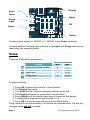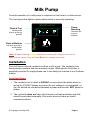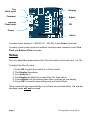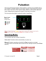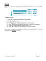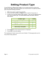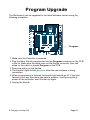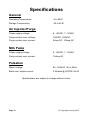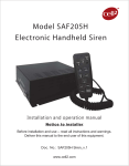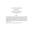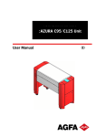
1
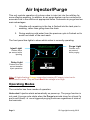
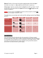
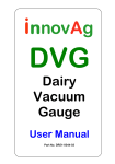
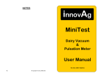
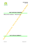
innovAg
ovAg
MultiControl
Universal Dairy
Controller
•
•
•
•
Air Injector/Purge
Pulsation
Milk Pump: Basic
Milk Pump: VariSpeed
User Manual
Part No. DR51-0045-03
InnovAg Pty Ltd
82 Victoria St. Sandringham 3191 Victoria, Australia
Ph +613 9521 9383 Fax +613 9521 8009
FreeCall (within Australia) 1800 061 167
email: [email protected]
www.innovag.com
A.C.N. 073 191 376
Page 1
© Copyright InnovAg 2010
The MultiControl Concept
MultiControl is an innovative range of high-technology dairy
controllers that are highly reliable, economical, versatile and easy
to set up. Although the range comes pre-packaged for individual
applications, each uses the same front panel electronics which
has distinct advantages:
1. Common setup method.
2. Single spare part for all the range.
3. Lower product cost.
This manual has sections for each controller type and includes
how to set up a new board should replacement be required.
© Copyright InnovAg 2007
Page 2
Air Injector/Purge
This unit controls operation of a dump valve to inject air into the milkline for
more effective washing. In addition, an air purge system can be controlled to
evacuate fluid in the milkline at appropriate times. Automatic air purge has two
main advantages:
1. Valuable milk remaining in the line is flushed into the tank prior to
washing, rather than going down the drain.
2. During washing cold water from the previous cycle is flushed out to
avoid cool-down of the next wash.
The front panel has lights to show which action is currently operating:
Purge Light
Inject Light
Flashes twice
per second while
injecting
Flashes once
per second
while purging
Delay Light
Flashes once per
second between
inject operations
Note: All lights flashing Orange means the incoming DC supply is too low for
MultiControl to work. They will flash Red if the voltage is too high.
Operating Modes
The controller has three modes of operation:
Auto-start: Injection starts automatically on power-up. The purge function is
not used. A purge cycle starts when the Purge terminals close for at least 1s
and is self-timed, i.e. once triggered purging continues regardless of state of
the terminals.
Page 3
© Copyright InnovAg 2010
Manual: Similar to Auto-start but Injection only operates while the Inject
terminals are closed, i.e. does not automatically start on power up.
Auto-purge: Injection operates while the Inject terminals are closed. A selftimed purge cycle starts when the Inject terminals open or Purge terminals
close for at least 1s.
NOTE: In auto-purge mode Inject terminals must be closed for at least 30s
before an auto-purge is allowed to start.
The table below summarizes each mode and the settings required (see Setup
section):
Inject
Purge
Setting #1
Setting #5
Power-on
0
0
Auto-start
Closes
Manual
Closed
1
0
1
1
Closes
Auto-purge
Closed
Closes
or
Opens
Installation
The unit has an internal solenoid valve for connection to Vacuum supply,
filtered air and the dump valve. A pair of isolated screw-terminals are provided
for connection of an external AC or DC solenoid for the Purge function. These
terminals are shorted when Air Purge operates so they should be wired in
series with the solenoid and its power supply.
© Copyright InnovAg 2007
Page 4
Display
Inject
Input
Purge
Input
Power
10-32
VDC
5s
10s
15s
20s
25s
30s
35s
40s
45s
50s
1
2
3
4
5
6
7
8
9
0
1.0s
2.0s
2.5s
3.0s
3.5s
4.0s
4.5s
5.0s
6.0s
7.0s
1 30s 1
2 40s 2
3 50s 3
4 60s 4
5 70s 5
6 80s 6
7 90s 7
8 100s 8
9 110s 9
0 120s 0
1 2 3 4 5
+
OK
Adjust
OK
AUTO
Select
Connect power supply (8 - 48VDC or 7 -36VAC) to the Power terminals.
Connect isolated, normally-open contacts to the Inject and Purge terminals as
required by the operating mode.
Setup
There are 5 adjustable parameters:
#1
#2
#3
#4
#5
Setting
External terminals enable
Delay time
Inject time
Purge time
Auto Purge enable
Range
Min.
Max
0
1
1
10 (0)
1
10 (0)
1
10 (0)
0
0
To adjust settings:
1. Press OK to place the controller in Setup mode.
2. The Display illuminates.
3. Turn Select to the required parameter number on the dial.
4. The Display will show the parameter’s current value.
5. Press Adjust until the desired new value is shown on the display.
6. To adjust more parameters repeat steps 3 to 5.
7. Press OK to save the new settings and exit Setup Mode.
Setup mode will exit automatically if no buttons are pressed within 10s and any
changes made will not be saved.
Page 5
© Copyright InnovAg 2010
Milk Pump
Controls operation of a milk pump in response to float level in a milk receiver.
The front panel has lights to show which action is currently operating:
MultiControl
Pump
Running
Float at Top
ON while the
float is at the top
position
ON while the float is
at the bottom
position
innovAg
ovAg
Float at Bottom
ON while the
pump is
enabled
Note: All lights flashing Orange means the incoming DC supply is too low for
MultiControl to work. They will flash Red if the voltage is too high.
Installation
The unit has an internal contactor to drive a milk pump. The contactor has
three primary contacts and one auxiliary contact. Although the Controller is
supplied pre-wired for single-phase use it can easily be re-wired to suit 3-phase
pumps.
Important Notes:
1. The contactor coil is rated at 240VAC so care should be taken when rewiring for 415VAC 3phase to ensure the coil voltage is not exceeded, i.e.
the coil should be connected between a phase and neutral, NOT phase to
phase.
2. The controller does not have inbuilt motor-overload protection and this
should be provided externally if the motor does not have an inbuilt
overload protector.
© Copyright InnovAg 2007
Page 6
Top
Float Input
Common
Display
T
B
Bottom
Float Input
10-32
10-32
VDC
VDC
Power
1s 1
1.0s 12 30s 1
2s
2.0s 2 40s 2
3
3s
2.5s 3 50s 3
3.0s 44 60s 4
4s
3.5s 5 70s 5
5s
4.0s 65 80s 6
4.5s 76 90s 7
6s
5.0s 8 100s 8
7s
6.0s 97 110s 9
7.0s 08 120s 0
8s
9s 9
10s
1 2
3 0
4 5
5s
10s
15s
20s
25s
30s
35s
40s
45s
50s
1
2
3
4
5
6
7
8
9
0
++
OKOK
Adjust
OK
AUTO
Select
Connect power supply (8 - 48VDC or 7 -36VAC) to the Power terminals.
Connect a level probe (must be isolated, normally-open contacts) to the Top
Float and Bottom Float terminals.
Setup
The only adjustable parameter is Run-On time which can be set from 1 to 10s.
To adjust the Run-On time:
1. Press OK to place the controller in Setup mode.
2. The Display illuminates.
3. Turn Select to 1.
4. The Display will show the current Run-On Time value.
5. Press Adjust until the desired new value is shown on the display.
6. Press OK to save the new setting and exit Setup Mode.
Setup mode will exit automatically if no buttons are pressed within 10s and any
changes made will not be saved.
Page 7
© Copyright InnovAg 2010
Pulsation
This unit controls three banks of 2x2 pulsators. Versions are available with inbuilt 12VDC or 24VDC switch-mode power supplies. Three banks for pulsator
drive lowers the load on the vacuum supply, allows smaller-sized cable and
lower voltage drops compared to single or dual bank controllers.
The front panel has lights to show the state of each Bank:
MultiControl
Bank Light
Flashes at
Pulsation Rate.
1
3
innovAg
ovAg
: Front ON
: Rear ON
: Both ON
: Fault
2
Note: All lights flashing Orange means the incoming DC supply is too low for
MultiControl to work. They will flash Red if the voltage is too high.
Operating Modes
The controller has two modes of operation:
Auto-start: Pulsation starts automatically on power-up.
Manual: Pulsation operates only while the Run terminals are closed.
The table below summarizes each mode and the settings required (see Setup
section):
Auto-start
Manual
Runs
Power-on
Closed
© Copyright InnovAg 2007
Setting #1
0
1
Page 8
Installation
The unit has three sets of Bank terminals for connection of Pulsators.
If the unit does not have in internal power supply connect the DC supply to the
Power terminals. Make sure the polarity is correct!
For units with an in-built power supply external equipment can be connected to
the Power terminals. Be careful not to overload the power supply.
The Red LED shows if power is present. An LED is also provided on each side
of all banks to indicate the side is correctly operating.
Display
Run
Input
%
Do not
use
50:50 60:40
55:45 60:40
60:40 65:35
65:35 70:30
70:30 50:50
50:50
55:45
60:40
65:35
70:30
CPM
1
2
3
4
5
6
7
8
9
0
1 2 3
50
55
60
65
90
120
150
180
-
1
2
3
4
5
6
7
8
9
0
+
OK
Adjust
OK
Select
Connect an isolated, normally-open contact to the Run terminals if external
control is required. Other terminals, if fitted, are not used.
Page 9
© Copyright InnovAg 2010
Setup
There are 3 adjustable settings (Rate and Ratio tables are shown on the PCB
label):
Range
Setting
Min.
Max
0
1
#1 External terminals enable
1
#2 Pulsation Ratio (%)
10 (0)
1
#3 Pulsation Rate (CPM)
10 (0)
To adjust settings:
7. Press OK to place the controller in Setup mode.
8. The Display illuminates.
9. Turn Select to the required parameter number on the dial.
10. The Display will show the parameter’s current value.
11. Press Adjust until the desired new value is shown on the display.
12. To adjust more parameters repeat steps 3 to 5.
13. Press OK to save the new settings and exit Setup Mode.
Setup mode will exit automatically if no buttons are pressed within 10s and any
changes made will not be saved.
© Copyright InnovAg 2007
Page 10
Setting Product Type
A new Multicontrol Board that is not set for a product type will continuously
flash all front panel LEDs white. Before use it must be set to a specific product
type using the following procedure:
1. Make sure power is off to the controller.
2. Press and hold the OK and Adjust buttons and turn the power on.
3. Continue to hold both buttons down (approx. 10s) until the display shows
the current product type. The table below shows the letters used for
each mode:Product Type
Air Injector/Purge
Letter
A
P
C
F
Pulsation
Milk Pump: Basic
Milk Pump: VariSpeed
4. Press Adjust until the desired product is displayed.
5. Press OK to save the setting.
The replacement board comes with a set of labels. Fit the appropriate one for
the product being repaired.
Page 11
© Copyright InnovAg 2010
Program Upgrade
The Multicontrol can be upgraded to the latest software version using the
following procedure:
%
50:50 60:40
55:45 60:40
60:40 65:35
65:35 70:30
70:30 50:50
50:50
55:45
60:40
65:35
70:30
CPM
1
2
3
4
5
6
7
8
9
0
1 2 3
50
55
60
65
90
120
150
180
-
1
2
3
4
5
6
7
8
9
0
+
OK
Program
1. Make sure the Controller is powered.
2. Plug the black Keyfob programmer into the Program connector on the PCB
in the lid. Make sure the white mark on the Keyfob connector (also red
stripe on the cable) is toward Program on the PCB.
3. Press the button on the Keyfob.
4. The Keyfob’s light should go green while the new software is being
transferred.
5. When programming is finished the Keyfob light should go off. If the light
flashes red at any time there has been a problem. Unplug everything,
power off the controller, wait 30s then try again.
6. Unplug the Keyfob.
© Copyright InnovAg 2007
Page 12
Specifications
General
Operating Temperature:
-5 to 40°C
Storage Temperature:
-20 to 60°C
Air Injector/Purge
Power supply voltage:
8 - 48VDC, 7 - 36VAC
Purge contact max. voltage:
100VDC, 250VAC
Purge contact max. current:
5Amp DC, 10Amp AC
Milk Pump
Power supply voltage:
8 - 48VDC, 7 - 36VAC
Pump contact max. current:
15Amp AC
Pulsation
Mains voltage:
85 - 264VAC, 50 or 60Hz
Bank max. output current:
2.5A/side @ 60CPM, 60:40
Specifications are subject to change without notice.
Page 13
© Copyright InnovAg 2010
Declaration of Conformity
Standards to which Conformity is declared:
• CISPR 11
• AS NZS 61000-6-4
• EN 61000-3-2
Manufacturer’s Name:
InnovAg Pty. Ltd.
Manufacturer’s Address: 82 Victoria St.
Sandringham
Victoria 3191
Australia
Type of Equipment:
Dairy Controls
Brand Name:
MultiControl Dairy Controller
Model Number:
DR40-0125
DR40-0126
DR40-0127
Pulsation Controller
Air Injector Controller
Milk Pump Controller
I, the undersigned, hereby declare that the equipment specified above
conforms to the above Directives and Standards.
Signature
Date: 18 December 2006
Braham Basser
Director
InnovAg Pty. Ltd
© Copyright InnovAg 2007
Page 14