1
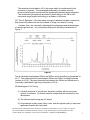
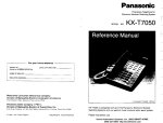
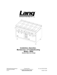
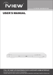
UV POWER-SHOT 1100
USER MANUAL
Distributed by:
cureUV.com
2855 S. Congress Ave.
Suite C
Delray Beach, FL 33445
Tel: (800) 977-7292
Fax: (561) 243- 2212
E-Mail: [email protected]
The information contained thereon is the property of SPDI, Inc. Reproduction or use in whole or in part of
this manual and the information thereon by anyone, except authorized persons in the furtherance of the
business SPDI,Inc. without the written consent of SPDI Inc. is STRICTLY PROHIBITED
Contents
General UV Curing Information ……………………………. 2
Lamp Information
UV Curing Principle
UV Safety ………………………………………………………. 4
Ultraviolet Safety
Thermal Safety
Ozone Safety
UV Lamp HandlingUV Processor Maintenance
System Reference …………………………………………….. 7
System Overview ………..…………………………………….. 8
Operating Instructions
Installing the Lamp …………………………………… 9
Turning the System On ……………………………… 9
Lamp Output Power …………………………………. 10
Using The Handheld ………………………………… 10
Powering Down the System ……………..…………. 11
Changing the Lamp ………………………..………… 11
Changing the Reflector ……………………………… 12
The information contained thereon is the property of SPDI, Inc. Reproduction or use in whole or in part of
this manual and the information thereon by anyone, except authorized persons in the furtherance of the
business SPDI, Inc. without the written consent of SPDI Inc. is STRICTLY PROHIBITED
1
General UV Curing Information
Lamp Information
The lamp emits large amounts of ultraviolet radiation, which can be
extremely harmful to eyes and skin. Great care should be taken to insure that
personnel are not exposed to direct or reflected radiation from the lamp. Suitable eye and
skin protection must be employed when lamp is in operation.
The lamp generates ozone gas during operation. Operating equipment and
work areas should be adequately ventilated to comply with the OSHA regulations for
ozone.
The lamp should be handled only when cold and with clean cotton gloves. Alcohol
can be used to remove fingerprints and all external foreign matter. Premature
devitrivication and dramatic poor lamp performance are directly related to a clean outer
surface.
UV Curing Principle
Ultraviolet curing is a photochemical process in which an abundant amount of UV energy
is produced by a mercury discharge lamp and focused at monomers through cross-linking
or polymerization. The sensitizer present in the monomer absorbs UV radiation at a rapid
rate and initials the reaction in the monomer, producing a hard dry surface. The rate or
speed of the curing process depends on the following:
(A) Chemical Compound – Each monomer will cure at a different rate, depending
upon the composition and amounts of sensitizer, pigment, and chemical
additives.
(B) Thickness of Coating – The thickness of a specific coating is not directly
proportional to exposure time. The amount of UV energy inside a layer of
coating decreases exponentially with depth. If 70% of the UV energy is
absorbed in the top .001” of coating, then 70% of the remainder or 7% of the
initial amount will be absorbed in the second .001” of coating. Thus, a two-fold
increase in thickness requires a ten-fold increase in UV intensity.
(C) Amount of UV per Unit Surface – Normally, the curing speed will increase with
the amount of UV energy per unit surface at a nonlinear rate. If a 200 watt per
inch mercury lamp was increased to 400 watt, the curing speed would increase
ten fold.
The information contained thereon is the property of SPDI, Inc. Reproduction or use in whole or in part of
this manual and the information thereon by anyone, except authorized persons in the furtherance of the
business SPDI, Inc. without the written consent of SPDI Inc. is STRICTLY PROHIBITED
2
The sensitizer should absorb UV in the range which is not absorbed by the
monomer or pigment. The wavelength produced by a medium mercury
pressure lamp should coincide with the wavelength absorbed by the sensitizer.
The continuous light spectrum produced by these lamps in the 200 to 440
nanometer range propels technology to a plateau of efficiency.
(D) The UV Spectrum – Once the basic concept of radiation has been understood,
how ultraviolet radiation fits into the scheme of things, and what UV curing
contains, then, one can easily understand the advantages and disadvantages
of various light sources. UV curing lamps display the following characteristic in
Figure 1.
Figure 1
The far ultraviolet lies between 200nm and 300nm and is classified as Germicidal or
UV-C. The middle ultraviolet lies between 280nm and 320nm is called Erythmea
(suntan) or UV-B. The near ultraviolet lies between the 320nm and 400nm and is
commonly called Black Light (long ultraviolet) or UV-A.
(E) Advantages of UV Curing
(1) A drastic reduction in “air pollution” becomes possible with the monomer
system of excitation. No solvent need be evaporated and expelled into the
atmosphere.
(2) The fast and rapid curing rate UV lamps.
(3) Huge savings in plant space, labor costs, and the highest quality in improved
appearance cannot be overlooked.
The information contained thereon is the property of SPDI, Inc. Reproduction or use in whole or in part of
this manual and the information thereon by anyone, except authorized persons in the furtherance of the
business SPDI, Inc. without the written consent of SPDI Inc. is STRICTLY PROHIBITED
3
UV Safety
Ultraviolet Safety…
The spectra available for ultraviolet curing and drying is quite varied. Coatings,
inks, and adhesives may be composed of formulations that require strong UV intensity of
various wavelengths. Longwave ultraviolet radiation (320-420 nanometers) is considered
most practical.
Shielding is absolutely mandatory. Medium pressure UV lamps radiate harmful UV
radiation that can cause serious burns to skin and eyes.
While thermal burns are felt immediately, UV burns are not felt for several hours.
Short exposure to lamp radiations can cause severe burning of skin and eyes. UV burn
of the eyes affects the cornea that takes several days to heal. UV burn is identical to
‘Welder’s Burn’ and will feel like sand in the eyes that cannot be washed out. The
discomfort is transitory. Extreme caution must be taken – high power UV radiation can
cause blindness.
Exposure to UV radiations, of only limited time, will evoke erythema on normal
skin. Such erythema is transitory and will not produce blistering, nor tanning, as only a
small amount of radiation penetrates the Malpighian layer. Extreme caution must be
taken – high power UV radiation can cause severe burns to the skin.
Shielding material can be of cloth, glass, plastic, wood, or metal. As infrared
energy is generated along with intense visible light, fireproof as well as opaque material
that does not degenerate under UV radiation must be utilized.
Direct light from the UV processor should not be visible to the operator nor other
personnel. Bounce (reflected) light should be minimized and avoided. Total shielding
with openings minimized for product entrance and egress from the UV processor should
be incorporated into processor design. Reflective surfaces coated with black UV
absorbing paint reduce reflected UV radiations. Protective clothing and safety spectacles
should be worn if optimum shielding cannot be attained.
Thermal Safety…
Infrared energy, an inherent product of the arc utilized to create UV energy in UV
processors, can cause overheating of processor components when adequate safeguards
are not incorporated into the UV processor design and application.
Cooled heat sinks should provide protection to the press, conveyor, and other
process components in or near the UV processor. The cooling system should be
carefully designed and properly maintained. In air-cooled systems, filters must be
The information contained thereon is the property of SPDI, Inc. Reproduction or use in whole or in part of
this manual and the information thereon by anyone, except authorized persons in the furtherance of the
business SPDI, Inc. without the written consent of SPDI Inc. is STRICTLY PROHIBITED
4
properly cleaned or replaced on a maintenance schedule related to powder, dust, and dirt
conditions where the UV processor is operating.
Halon type fire extinguishers are to be used in the event of fire. CO2 fire
extinguishers with dry chemical or water are NOT recommended.
If a fire occurs, all residue of damaged substrate should be removed from curing
area. Soot and ash must be cleaned from lamps and reflectors before re-start.
Investigation to determine the malfunction causing the fire is most important.
Correction must be made to eliminate re-occurrence.
UV processor electrical systems should be serviced only by qualified electricians.
Ozone Safety…
Triatomic oxygen or ozone (O3) is the only by-product of the UV lamp. It is formed
by oxygen being exposed to 254nm wavelengths of UV energy.
Ozone can be effectively eliminated in the processing area by exhausting air of the
cooling system of the UV processor to outside the building. Such exhausting has no
danger as the hot gas is very unstable and breaks down to oxygen rapidly in ducting.
UV Lamp Handling…
Fused quartz (Silicon di-oxide, SiO2) with a high melting point and excellent UV
transmissivity is used in fabrication of UV processor lamps. A 22 x 25 mm diameter tube
with wall thickness of 1.0 to 1.5 mm used with tungsten electrodes sealed into each end is
typical. Lamps are manufactured from 1” to 180: arc length. Quartz is very fragile and
special cushioned packaging is utilized for safe transportation.
Upon receiving new lamps the carton should be opened fully so the lamp can be
lifted out of the packaging with no twisting or pulling. Unpacking should take place in an
area large enough to eliminate the possibility of inadvertently striking lamp against walls,
pillars, pipes, beams, or machinery.
Lamp must be wiped with alcohol before placing in service. Bare skin contact with
the quartz envelope must be avoided. Compounds from the skin when heated on lamps
operating at 600o to 850o C will form permanent etching (devitrification) on the quartz
surface, decreasing UV energy transmission. A contaminated lamp eventually will
overheat causing premature failure.
The information contained thereon is the property of SPDI, Inc. Reproduction or use in whole or in part of
this manual and the information thereon by anyone, except authorized persons in the furtherance of the
business SPDI, Inc. without the written consent of SPDI Inc. is STRICTLY PROHIBITED
5
UV Processor Maintenance…
Lamps and reflectors must be clean at the time of installation and maintained so
the UV energy generated can reach the ink or coating.
Since the UV processor is an optical system, all types of dust, powder, grease,
smoke, and coatings must be cleaned from the lamp and reflectors. Electrical fittings
must also be kept clean to prevent arcing between fitting and lamp ends.
Dirty reflectors will reduce cure rates and increase temperature. The reflectors
return approximately 50-60% of lamp energy. Overheating from a dirty condition can
cause warping, possibly reducing electrical spacing, and cause a short of the arc to
ground.
A mild detergent and distilled water mixed at a ratio of 1¼ ounces to 1 gallon
makes a good cleaning solution. After cleaning, rinse with clear distilled water and wipe
or polish with a clean cloth.
Grease or ink on the lamp or reflectors will require washing with a solvent rather
than cleaning with a detergent solution. Clean alcohol or ammonia and distilled water can
also be used for cleaning. The use of steel wool, emery paper, or abrasive powders is
not recommended for cleaning lamps or reflectors.
CAUTION
Ultraviolet lamps emit radiation, which is harmful to eyes and skin. Great care should
be taken to insure that personnel are not exposed to direct or reflected light.
The information contained thereon is the property of SPDI, Inc. Reproduction or use in whole or in part of
this manual and the information thereon by anyone, except authorized persons in the furtherance of the
business SPDI, Inc. without the written consent of SPDI Inc. is STRICTLY PROHIBITED
6
System Reference
POWER REQUIREMENTS:
Standard:
120 Volts / 60 Hz
15 Amps
LAMP:
Switchable 1100W (Full) / 500W (Stand-By)
REPLACEMENT PARTS:
Lamp Part #: 101100
Reflector Part #: 191100
RECOMMENDED SAFETY EQUIPMENT:
Faceshield: Part # 302202
Protective Gloves: Part # 302003
Lab Coat: Part # 302004
Replacement Lamps & Reflectors can be purchased at www.cureUV.com
The information contained thereon is the property of SPDI, Inc. Reproduction or use in whole or in part of
this manual and the information thereon by anyone, except authorized persons in the furtherance of the
business SPDI, Inc. without the written consent of SPDI Inc. is STRICTLY PROHIBITED
7
SYSTEM OVERVIEW
The UV POWER-SHOT 1100 is comprised of the Power Supply Unit, UV
Lamp Irradiator and the Irradiator Stand-By Nest.
Figure 2
Figure 3
Figure 4
The information contained thereon is the property of SPDI, Inc. Reproduction or use in whole or in part of
this manual and the information thereon by anyone, except authorized persons in the furtherance of the
business SPDI, Inc. without the written consent of SPDI Inc. is STRICTLY PROHIBITED
8
OPERATING INSTRUCTIONS
CAUTION:
ALL EXPOSED SKIN IS TO BE COVERED AND EYE PROTECTTON
MUST BE WORN WHILE OPERATING THE UV POWER-SHOT
AT ALL TIMES DURING THE OPERATION OF THIS SYSTEM KEEP ALL THE COOLING
FANS FREE FROM OBSTRUCTION AND OBSERVE UV SAFETY PROCEDURES.
INSTALLING THE LAMP
Use cotton gloves when handling the lamp; any fingerprints or dirt on the quartz can
damage the lamp when the lamp heats up.
Always make sure the power is disconnected before installing the lamp.
It is not necessary to disassemble the irradiator to install the lamp. The two ceramic
receivers that hold the lamp are spring-loaded.
1. Put one end of the lamp in to the ceramic receiver.
2. Push the opposite receiver with you thumb.
3. Position the end of the lamp into the second receiver.
Figure 5
TURNING THE SYSTEM ON
1. Connect the power cord that is included with the system to the connector on the
back of the Power Supply Unit.
.
2. Place the UV Irradiator in to the Irradiator Stand-By Nest
3. Press the Power Switch to the ‘ON’ position.
4. To turn on the lamp press the Lamp Switch to the ‘ON’ position.
5. The lamp will operate in warm-up mode for about 2 minutes, after which the
system is ready to use.
The information contained thereon is the property of SPDI, Inc. Reproduction or use in whole or in part of
this manual and the information thereon by anyone, except authorized persons in the furtherance of the
business SPDI, Inc. without the written consent of SPDI Inc. is STRICTLY PROHIBITED
9
LAMP OUTPUT POWER
Lamp Output Power can be adjusted
via the switch on the UV Irradiator see
Figure 6.
When the lamp is sitting at rest in the
Irradiator Stand-By Nest the Lamp
Output Power will automatically switch
to Stand-By Power.
Figure 6
WARNING: The UV Lamp generates heat even when in the Stand-by
power setting. Caution should be taken not to place anything
flammable under the lamp or concentrate the lamp on a particular
product for too long.
USING HANDHELD
CAUTION
Ultraviolet lamps emit radiation, which is harmful to eyes and skin. Great care
should be taken to insure that personnel are not exposed to direct or reflected light.
Hold the handheld unit so that the lamp is
directed away from you. Pass the lamp
at a height of 2-3” over the object that is to
be cured. Keep the lamp moving as it
could burn or over cure the coating or
adhesive that is being cured. Test the
curability of your material before using the
UV Power-Shot on the item that you are
working on.
A single slow and steady pass of the lamp
over the object should be enough for a full
cure.
Figure 7
The information contained thereon is the property of SPDI, Inc. Reproduction or use in whole or in part of
this manual and the information thereon by anyone, except authorized persons in the furtherance of the
business SPDI, Inc. without the written consent of SPDI Inc. is STRICTLY PROHIBITED
10
POWERING DOWN THE SYSTEM
Use the ‘Lamp Power’ switch to turn the lamp off. This will power-down the lamp but keep
power to the cooling fans.
Allow enough time for the system to cool (about 5 minutes) before disconnecting the
power.
Once the lamp has been powered-down, it may take a few minutes before the lamp is
cool enough to be powered back up again. If during this time an attempt is made to power
the lamp, it will not ignite.
CHANGING THE LAMP
Always make sure the power is disconnected and the lamp is cool before removing.
It is not necessary to disassemble the irradiator to replace the lamp. The two ceramic
receivers that hold the lamp are spring-loaded.
To remove the lamp:
1. Push one of the ceramic receivers to the side.
2. Lift the lamp from this receiver
3. Lamp should be easily removed.
To reinstall the lamp: (See Figure 5 on page 9)
1. Put one end of the lamp in to the ceramic receiver.
2. Push the opposite receiver with you thumb.
3. Position the end of the lamp into the second receiver.
The information contained thereon is the property of SPDI, Inc. Reproduction or use in whole or in part of
this manual and the information thereon by anyone, except authorized persons in the furtherance of the
business SPDI, Inc. without the written consent of SPDI Inc. is STRICTLY PROHIBITED
11
CHANGING THE REFLECTOR
Remove the lamp prior to changing or installing the reflector.
Remove the lamp housing from the irradiator outer shell by
undoing the four corner screws on the side with the handle
Carefully pull the lamp housing out of the shell.
Pop the reflector out of the retaining bar by pushing your
thumbs on the back side of the reflector.
Rotate the reflector out of the housing.
With the old reflector removed, replace with a new reflector.
The information contained thereon is the property of SPDI, Inc. Reproduction or use in whole or in part of
this manual and the information thereon by anyone, except authorized persons in the furtherance of the
business SPDI, Inc. without the written consent of SPDI Inc. is STRICTLY PROHIBITED
12
Rotate new reflector in to the housing.
Line up the edge of the reflector with the retaining bar.
Snap in to the retaining bar by pressing on the front top
edge of the reflector with your thumbs.
Slide lamp housing back in the irradiator outer shell.
Reinstall screws in to the end plate.
The information contained thereon is the property of SPDI, Inc. Reproduction or use in whole or in part of
this manual and the information thereon by anyone, except authorized persons in the furtherance of the
business SPDI, Inc. without the written consent of SPDI Inc. is STRICTLY PROHIBITED
13