1
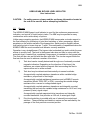
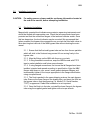
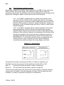
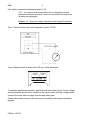
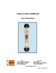
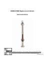
KOBOLD NBK Bypass Level Indicator
User Instructions
KOBOLD Instruments Inc. 1801 Parkway View Drive Pittsburgh PA 15205
Phone (412) 788-2830 • Fax (412)-788-4890 • www.koboldusa.com
Manual-NBK_10-4-02
NBK
Table Of Contents
KOBOLD NBK BYPASS LEVEL INDICATOR
1.0
General . . . . . . . . . . . . . . . . . . . . . . . . . . . . . . . . . . . . . . . . . . . . . . . . . . . . 1
2.0
Specifications . . . . . . . . . . . . . . . . . . . . . . . . . . . . . . . . . . . . . . . . . . . . . . . . 2
3.0
Installation Instructions. . . . . . . . . . . . . . . . . . . . . . . . . . . . . . . . . . . . . . . . . 3
3.1
Mechanical Installation. . . . . . . . . . . . . . . . . . . . . . . . . . . . . . . . . . . . 3
3.2
Switch Electrical Installation. . . . . . . . . . . . . . . . . . . . . . . . . . . . . . . . 4
3.3
Transducer Electrical Installation. . . . . . . . . . . . . . . . . . . . . . . . . . . . 5
4.0
Operation . . . . . . . . . . . . . . . . . . . . . . . . . . . . . . . . . . . . . . . . . . . . . . . . . . . 7
5.0
Arrival of Damaged Equipment . . . . . . . . . . . . . . . . . . . . . . . . . . . . . . . . . . 7
6.0
Maintenance. . . . . . . . . . . . . . . . . . . . . . . . . . . . . . . . . . . . . . . . . . . . . . . . . 7
7.0
Need Help With Your NBK?. . . . . . . . . . . . . . . . . . . . . . . . . . . . . . . . . . . . . . 8
List of Diagrams
Diagram 3.1
Switch Wiring . . . . . . . . . . . . . . . . . . . . . . . . . . . . . . . . . . . . . 4
Diagram 3.2
Wiring for Resistance Analog Transducer with Remote
transmitter . . . . . . . . . . . . . . . . . . . . . . . . . . . . . . . . . . . . . . . 5
Diagram 3.3
Wiring for Analog Transducer with Integral Transmitter. . . . . . 6
List of Tables
Table 2.1:
General Specifications & Operational Limits . . . . . . . . . . . . . . . . . . . 2
Table 2.2:
Electrical Data. . . . . . . . . . . . . . . . . . . . . . . . . . . . . . . . . . . . . . . . . . 2
FM Rev. 10/4/02
NBK
KOBOLD NBK BYPASS LEVEL INDICATOR
User Instructions
CAUTION:
1.0
For safety reasons, please read the cautionary information located at
the end of the manual, before attempting installation.
General
The KOBOLD NBK Bypass Level Indicator is used for the continuous measurement,
indication, and control of liquid levels in tanks. The NBK may be specified in many
combinations with a wide variety of options.
Unlike many competing products, the KOBOLD NBK incorporates a circular magnet in
the float, allowing for positioning of point level switches, or other accessories, almost
anywhere on the exterior surface of the bypass tube. Switch position flexibility allows
level switch points to be as close as 1" apart. This combination of capabilities makes the
KOBOLD NBK the most versatile level indicator currently available.
Operation is very straightforward. The bypass tube is attached to a tank in which the user
wishes to monitor level. The level in the bypass tube rises and falls in unison with the
main tank level. A sealed float, containing a ring magnet, is inserted into the bypass tube.
The float will then rise and fall with the main tank level. The circular magnet inside the
float can then be used to achieve a number of functions:
1)
Tank level can be visually determined through use of externally mounted
magnetic indicators. Depending on the direction of float travel, the
indicators are rotated with the magnetic field surrounding the float to
expose either red or white surfaces.
2)
Tank level may be determined electronically via several methods:
A magnetically-coupled resistance transducer with a variable bridge
resistance, proportional to float height.
A magnetically-coupled restistance transducer and a KOBOLD remote
transmitter (Model: DFM, DST or DFA), converting the variable bridge
resistance into a current or voltage based signal.
A magnetically-coupled resistance transducer and integrally mounted
transmitter that converts the variable bridge resistance to a 4-20 mA, looppowered (2-wire) signal output.
A magnetically-coupled magnetostrictive transducer and integrally
mounted transmitter that provides a 4-20 mA, 4-wire signal output.
3)
Point level switching is possible with use of externally-mounted reed
switches . These switches are bistable in nature and are switched by the
passage of the float past their mounted position.
FM Rev. 10/4/02
NBK
2.0
2
Specifications
Table 2.1: General Specifications & Operational Limits
Bypass tube:
Material:
Maximum operating pressures:
Maximum operating temperature
With polypropylene rollers:
With ceramic rollers:
With switches:
With transducer:
Transducer with heat shield:
Maximum Viscosity:
Minimum liquid S.G.:
Minmum measuring length:
Maximum measuring length:
Overall length:
Ø 60.3 mm
1.4571 (316-Ti SS)
230, 580, 930, 1450 PSIG
212°F
750°F
see Table 2.2
390°F
750°F
200 cPs
0.55
12"
19.7' single section, longer in two-piece
dependent on measuring length
Table 2.2: Electrical Data
Limit contact:Option "R"
Contact operation:
Switching hysteresis:
Switch capacity:
Medium temperature:
Ambient temperature:
Protection:
Connection:
Housing:
bistable SPDT contact
approximately 15 mm
0.5A, 60VA, 220 VAC max.
250°F max.
160°F max.
IP 65 (NEMA 4X)
10' PVC cable
Polyamide
Limit contacts: Options "RH","RHH"
Contact operation:
Switching hysteresis:
Switch capacity:
Medium temperature:
Ambient temperature:
Protection:
Housing:
FM Rev. 10/4/02
bistable SPDT contact
approximately 15 mm
0.5A, 60VA, 220 VAC max.
424°F max. (RH) / 750°F max. (RHH)
160°F max.
IP 65 (NEMA 4X)
Die-Cast Aluminium, clamp connection
3
3.0
NBK
Installation Instructions
CAUTION:
3.1
For safety reasons, please read the cautionary information located at
the end of the manual, before attempting installation.
Mechanical Installation
Magnetically operated level indicators are precision measuring instruments and
should be treated with appropriate care. Check that all components have been
provided and that the connection flanges of the tank and indicator match. Once
this has been done, the level indicator may be mounted. We recommend that
(when possible) the bypass tube connections on your tank be fitted with valves to
allow servicing and removal of the NBK bypass tube without draining the main
vessel.
3.1.1 Ensure that the float and bypass tube are free from ferrous particles
which will stick to the float and may prevent it from moving freely in the
bypass tube.
3.1.2 Align the fittings on the NBK with those on your tank.
3.1.3 If using threaded connections, wrap the NBK threads with PTFE
tape to make installation and future removal easier.
3.1.4 If using flanged connections, first insure that all flanges have been
installed, oriented and spaced according to specification. Align the NBK
flanges with those on your vessel, insert gaskets between flanges, and
incrementally tighten to the torque appropriate to the flange classification
using a torque wrench.
3.1.5 The float is packed in the same shipping crate as the main bypass
tube. Remove the lower flange of the bypass tube, and insert the float into
the bypass tube so that the engraving (i.e. Media S.G., Serial Number,
“TOP”) is uppermost. Radial float orientation is not important.
3.1.6 Once the float is in the tube, re-install the lower flange to the bypass
tube using the supplied gasket and tighten with a torque wrench.
FM Rev. 10/4/02
NBK
4
3.2
Switch Electrical Installation (option)
Magnetically coupled limit switches may be mounted on the NBK for level control and
alarm functions. The annular design of the NBK float magnet allows, within the
guidelines outlined below, the switches to be positioned anywhere along the length of the
bypass tube, although no higher or lower than the inlet and outlet ports.
3.2.1 If your NBK is equipped with the optional visual indicator roller
assembly, mark the location of the assembly with respect to the bypass
pipe using a pencil or permanent marker. Additionally, mark the top of the
indicator roller assembly for reference. Support the indicator assembly as
appropriate, loosen the band clamps and remove. Place in a safe location
for later installation.
3.2.2 If your NBK is equipped with the optional magnetic reed contacts
(packed separately), mount the switch to the bypass tube using the
supplied clamps, with the wiring termination (wire or cable gland) facing
downward. Allow sufficient clearance for reinstallation of the indicator roller
assembly (if equipped). Ensure that the supply voltage and current is in
accordance with the switch specifications, and are not exceeded even
MOMENTARILY. If in doubt about possible loads, we suggest the use of
contact protection relays to protect your reed switches. Electrical
connections are made according to the wiring diagram as follows:
Diagram 3.1: Switch Wiring
All switches have three connection points: Blue (1), Black (2), and Brown (3).
The Black wire (2) is the common for both switching functions (N/O or N/C).
Blue (1)
N/O Dry (float below the switch), closes on rising level
Brown (3)
N/C Dry (float below the switch), opens on rising level
The float must initially pass by the switch once in each direction so that the switching
function will be as shown in the wiring diagram and table. After the switch has been
initialized, it is ready for operation and requires no maintenance.
FM Rev. 10/4/02
5
NBK
3.2.3 Adjust the switch by sliding the switch along the length of the bypass
tube and secure the clamp when at the desired level. Note: Hysteresis is
the difference between contact closing and opening points. A hysteresis of
approximately 15 mm of float travel is typical for all switches. You may
need to readjust your setpoint to accommodate this difference.
3.2.4 If equipped, reinstall the indicator roller assembly (referencing the
marks made upon removal) and secure the clamp assemblies.
3.3
Transducer Electrical Installation (option)
The transducer is shipped from the factory, mounted and aligned on the exterior of the
NBK bypass tube. The transducer mounting lugs are permanently welded to the bypass
tube and are unable to be relocated. If it becomes necessary to remove the transducer
for any reason, be sure to accurately mark the location of the assembly with respect to
the bypass tube using a pencil or permanent marker.
3.3.1 If a variable resistance level transducer has been provided with a
remotely mounted kobold controller/transmitter (model: DFA, DFM, DST),
connections are made according to the following wiring diagram:
Diagram 3.2 Wiring for Resistance Analog Transducer with Remote
Transmitter
wiring to DFA, DFM, DST
Transducer Alone
Full scale output
resistance
5000 ohm
(approx)
Wire Color:
Sensor (Internal)
Terminal 1:
White
Yellow
Terminal 2:
Brown
Red
Terminal 3:
Green
Black
Please Note: Wiring to terminals 1 & 2 may occasionally differ from what is shown in the
diagram, depending on the desired output behavior (typically: min. level = 4mA, max.
level = 20 mA) If an inverted response is desired (i.e. min. level = 20mA, max. level = 4
FM Rev. 10/4/02
NBK
6
mA), simply swap wiring between terminals 1 & 2.
3.3.2 If a continuous level transducer with an integrally mounted
transmitter has been provided, it must be connected according to the
following wiring diagram:
Diagram 3.3 Wiring for Analog Transducer with Integral Transmitter
Type 1: Resistor Chain with 2-wire transmitter (option: “RTW”)
Type 2: Magnetostrictive sensor with 4-20 mA, 4-wire transmitter
4-20 mA
Output
24 VDC In
± 20%
+ Out - Out +V
GND
To minimize interference caused by electrical fields from other circuits, the low-voltage
and signal cables should not be installed in the same conduit with high voltage cables.
Unscrew the cover and run supply lines through cable gland.
Connect the remote sensor to the electronics according to the terminal connection
diagram.
FM Rev. 10/4/02
7
NBK
NOTE: The controller/transmitter is delivered fully calibrated and ready for use. The
calibration screws found inside the electronics housing need not be adjusted by the
user. Customer adjustment of these screws often necessitates a recalibration of the
unit. The precision of the instrument is guaranteed only if the calibration screws have
not been adjusted. Contact Kobold Instruments for information if adjustment is
deemed necessary.
4.0
Operation
4.0.1 Slowly open the drain plug or valve at the bottom of the unit to
release any remaining liquid or gas and then close.
NOTE: It is imperative that vents or drains fitted to the indicator are
tightly closed prior to and during operation.
4.0.2 Slowly open upper isolation valve (if installed).
4.0.3 Slowly open lower isolation valve (if installed).
4.0.4 Verify that the installation is free of any leaks and repair if necessary.
The liquid will now flow into the bypass tube, lifting the float with it. The bypass tube will
continue to fill until the same level as in the main vessel is reached. As the float rises, all
externally mounted options (limit switches, level indicator, analog transducer) will be
activated as the float passes by their location. Switches will change state, visual level
indicators will turn from white to red, and analog output transducers will increase their
output signal. Your NBK is now in full operation.
5.0
Arrival of Damaged Equipment
Your instrument was inspected prior to shipment and found to be defect-free. If damage
is visible on the unit, we advise that you carefully inspect the packing in which it was
delivered. If damage is visible, notify your local carrier at once, since the carrier is liable
for a replacement under these circumstances. If your claim is refused, please contact
Kobold Instruments for further advisement.
6.0
Maintenance
The KOBOLD NBK normally requires very little maintenance, provided the measured
medium is kept free of contaminants. Ferritic pollutants may affect this device due to the
incorporation of magnets into the float assembly. From time to time, the drain plug or
valve should be opened to drain out any dirt particles present in the measured liquid.
Where dirt is not present, this procedure is not normally required.
FM Rev. 10/4/02
NBK
8
Some installations may require regularly scheduled maintenance due to use with coating
type media. When the NBK is used to monitor the level of this type of liquid, we
recommend that periodically, the bottom flange, (or top and bottom flanges, if equipped)
should be removed and the float carefully extracted. The bypass tube may then be
mechanically cleaned, the unit re-assembled and placed back in service.
7.0
Need help with your NBK Level Indicator?
Call one of our friendly engineers at 412-788-2830.
FM Rev. 10/4/02
9
NBK
Caution
PLEASE READ THE FOLLOWING GENERAL LEVEL METER / MONITOR
WARNINGS BEFORE ATTEMPTING INSTALLATION OF YOUR NEW
DEVICE. FAILURE TO HEED THE INFORMATION HEREIN MAY
RESULT IN EQUIPMENT FAILURE AND POSSIBLE SUBSEQUENT
PERSONAL INJURY.
FM Rev. 10/4/02
NBK
10
•
User's Responsibility for Safety: KOBOLD manufactures a wide range of
process sensors and technologies. While each of these technologies are
designed to operate in a wide variety of applications, it is the user's
responsibility to select a technology that is appropriate for the application,
to install it properly, to perform tests of the installed system, and to maintain
all components. The failure to do so could result in property damage or
serious injury.
•
Inspect instrument for damage upon arrival: Cracked, fractured, bent or
otherwise damaged instruments must not be put into use, since the device
is weakened to an unknown extent. Refer to Section 5.0, Arrival of
Damaged Equipment, for additional information.
•
Media and Chemical Compatibility: The maximum tolerances of the
device have been determined using water. If using other media, especially
corrosive media, it is critically important that the user determine chemical
compatibility with our instruments. KOBOLD Instruments Inc. cannot
accept responsibility for failure and consequences resulting from use of
media other than water.
•
Material Compatibility: Make sure that the model which you have
selected is chemically compatible with the application liquids. While the
meter is liquid and spray resistant when installed properly, it is not
designed to be immersed.
•
Proper Installation in System: Install the device in a fully supported
position within your system. This avoids excessive stresses which may
damage the instrument. In particular:
a.) Ensure that the plumbing leading to and from the instrument is fully
supported and that the instrument does not perform the physical function of
a joint.
b.) When calculating stress on the device caused by plumbing, the weight
of the medium in the pipes must be considered as well.
c.) Misaligned runs of rigid piping can cause large stresses when
connected to the instrument. Do not connect in such a fashion.
d.) When connecting fittings, hold the instrument fittings rigid with a
correctly sized wrench. Do not install by twisting the instrument into the
pipe fittings.
e.) Do NOT install by holding the device housing to provide counter-torque
to the pipe fitting.
f.) Use an appropriate amount of PTFE tape on male threads of fitting.
This reduces the twisting stresses produced by tightening the fittings into
each other.
g.) Do not use pliers or wrenches on the housing, as this may damage it.
FM Rev. 10/4/02
11
NBK
h.) Do not overtighten, as this may fracture the fittings.
•
Wiring and Electrical: Section 2.0, Specifications and Section 3.0,
Installation Instructions, provide the voltage and current limitations and the
wiring for the various sensor types. The sensor electrical ratings should
never be exceeded. Electrical wiring of the sensor should be performed in
accordance with all applicable national, state and local codes.
•
Temperature and Pressure: Section 2.0, Specifications, provides the
temperature and pressure limits for each model. Operation outside these
limitations will cause damage to the unit and can potentially cause personal
injury. Freezing of water in the instrument must be avoided since the
resultant expansion will damage the unit and make it unsafe for use
•
Make a Fail-safe System: Design a fail-safe system that accommodates
the possibility of switch or power failure. In critical applications, KOBOLD
recommends the use of redundant backup systems and alarms in addition
to the primary system.
FM Rev. 10/4/02