1
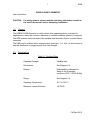
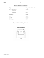
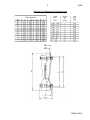
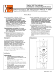
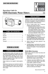
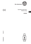
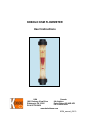
KOBOLD KSM FLOWMETER
User Instructions
USA
1801 Parkway View Drive
Pittsburgh, PA 15205
PH 412-788-2830
Canada
9A Aviation
Point Claire, QC H9R 4Z2
PH 514-428-8090
www.koboldusa.com
KSM_manual_08-10
Table of Contents
1.0
General .............................................................................................
1
2.0
Specifications ...................................................................................
1
3.0
Installation instructions......................................................................
4
3.1
Mounting ................................................................................
4
Operation ..........................................................................................
5
4.1
Reading the Flow Rate ..........................................................
5
4.2
Adjusting the Setpoints; KSM -5000/6000 .............................
5
4.3
Operating the Setpoints; KSM -5000/6000 .............................
5
5.0
Maintenance ......................................................................................
6
6.0
Arrival of Damaged Equipment ..........................................................
6
7.0
Need Help With Your KSM .................................................................
6
4.0
List of Diagrams
Diagram 2.3
Switch Wiring Schematic .........................................
2
Diagram 2.4
Dimensions & Pressure Loss ....................................
3
Table 2.1
Technical Data ...............................................................
1
Table 2.2
Material construction .....................................................
2
Table 2.5
Reed Contacts - Technical Data ...................................
4
List of Tables
1
KSM
KOBOLD KSM FLOWMETER
User Instructions
CAUTION:
1.0
For safety reasons, please read the cautionary information located at
the end of the manual, before attempting installation.
General
The KOBOLD KSM flowmeter is a high volume flow measuring device, intended for
applications in which the corrosion resistance of synthetic materials (plastics) is required.
The KSM operates on the principle of the variable area flowmeter (float in a conical tube or
rotameter).
The KSM may be outfitted with a setpoint switch (reed type - 1 or 2 pc.) to allow control of
external electronics by triggering upon flow rate changes.
2.0
Specifications
Table 2.1; Technical Data
Operating Principle:
Variable area
Dimensions:
See Diagram 2.4
Display:
Direct reading, calibrated for
Water or Air at standard
conditions (20°C, 0 PSIG Outlet)
Range:
See Diagram 2.4
Operating Temperature:
32° F to 140° F
Maximum Internal Pressure:
145 PSIG
FM Rev 08/10
KSM
2
Table 2.2; Materials of Construction
Body:
Trogamid-T or Polysulfone
Float: KSM- X001 to
KSM-X300
PVDF
KSM-X600
PVC
Float Stops:
PVDF
O-Rings:
EPDM
End Fittings:
PVC
Diagram 2.3: Switch Wiring Schematic
FM Rev 08/10
3
KSM
Diagram 2.4; Dimensions & Pressure Loss
FM Rev 08/10
KSM
4
Table 2.5; Reed Contact - Technical Data
Maximum Voltage:
230 VAC
Maximum Current:
0.5 A
Maximum Power:
10 W /12 VA
Switch Hysteresis:
3-12 mm
Maximum Ambient Temperature: 32° F to 130° F
3.0
Installation Instructions
CAUTION:
For safety reasons, please read the cautionary information located at the
end of the manual, before attempting installation.
NOTE:
Before installation, remove any protective netting surrounding the float
within the metering tube and discard. This netting is for shipping purposes only.
3.1 - Mounting
The KSM is supplied with PVC end connectors and PVC cap nuts as standard. To install the
instrument, simply:
1. Remove cap nuts and end fittings from your KSM.
2. Place cap nut over pipe to which you wish to connect.
3. Per manufacturer's instructions, use a PVC adhesive/solvent to glue fittings in
place and let cure.
4. Fasten connectors to KSM with PVC nuts. Take care not to overtighten the nuts.
If necessary, use a strap wrench on the nuts. Do NOT use a pipe wrench, pliers, or
any other sharp instrument on the fittings, as this may compromise the strength,
and eventual safety, of the instrument.
Alternately, the KSM can be ordered with an optional NPT threaded fittings; alter the
installation procedure accordingly. Use an appropriate thread sealant.
NOTE: The KSM must be installed vertically (long axis), with the inlet at the bottom.
FM Rev 08/10
5
4.0
KSM
Operation
We recommend that, if possible, the medium be introduced to the instrument in gradually
increasing amounts. This procedure serves two basic functions:
1. It prevents oscillation of the float upon sudden introduction of media
(particularlygases).
2. It prevents possible damage to the instrument caused by pressure surges (as
described in the cautionary section).
4.1 - Reading the Flow Rate
Flow rates measured by float type devices are typically read at the largest float diameter.
In the case of the KSM, this is the top edge of the float.
4.2 - Adjusting the Setpoint; KSM...-5000/6000 series
To adjust a setpoint:
1. Loosen the holding screw found on the setpoint indicator body, near the
V-groove.
2. Slide the switch to the desired setpoint value.
3. Tighten the holding screw, taking care not to overtighten.
4. Verify desired operation with media flowing and adjust if necessary.
4.3 - Operating the Setpoints; KSM...-5000/6000 series
Typical reed switch operation is as follows:
The setpoint switch is actuated by the motion of the magnet-containing float past the
switch position. The behavior of the switch is bistable - that is, the switch toggles from
one state to the other whenever the float passes, and remains in that state until the float
again passes back in the reverse direction. Since a reed switch is a switch in the purest
sense, external electronics may be driven directly through it, provided that the electrical
current/power loads are not demanding or excessive. (See Table 2.4 for reed switch performance data.)
Should switching of currents or voltages in excess of the abilities of the reed switch be
required, a suitable isolation relay must be installed.
FM Rev 08/10
KSM
5.0
6
Maintenance
The major enemy of float-type flowmeters is dirt. We recommend that clean or filtered
media only, be passed through the device. If using the setpoint switch, it is particularly
important to guard from contamination by ferritic (metal) materials. To protect from
these, we suggest the installation of a magnetic filter, such as a KOBOLD MFR.., or
equivalent.
6.0
Arrival of Damaged Equipment
Your instrument was fully inspected prior to shipment and found to be defect-free. If
damage is visible on the unit, we advise that you carefully inspect the packing in which it
was delivered. If damage is visible, notify your local carrier at once, since the carrier is
liable for a replacement under these circumstances. If your claim is refused, please
contact KOBOLD Instruments for further advisement.
7.0
Need help with your KSM?
Call one of our friendly engineers at 412-788-2830.
FM Rev 08/10
7
KSM
Caution
PLEASE READ THE FOLLOWING GENERAL FLOW METER/ MONITOR
WARNINGS BEFORE ATTEMPTING INSTALLATION OF YOUR NEW
DEVICE. FAILURE TO HEED THE INFORMATION HEREIN MAY
RESULT IN EQUIPMENT FAILURE AND POSSIBLE SUBSEQUENT
PERSONAL INJURY.
FM Rev 08/10
KSM
8
•
Inspect instrument for damage upon arrival. Cracked, fractured, bent or otherwise
damaged instruments must not be put into use, since the device is weakened to an
unknown extent. (The operations and installation guide will explain how to make a
claim on damaged instruments.)
•
Under NO circumstances must the maximum tolerances (temperature and pressure)
be exceeded.
•
The maximum tolerances of the device have been determined using water, air and/or
oil. If using other media, especially corrosive ones, it is critically important that the
user determine chemical compatibility with our instruments. A list, detailing material
composition of our instruments, is available from KOBOLD Instruments Inc. upon
request. KOBOLD Instruments Inc. cannot accept responsibility for failure and
consequences resulting from use of media other than water, mineral oil, air, and
nitrogen.
•
Install the device in a fully supported position within your flow system. This avoids
excessive stresses which may damage the instrument. In particular:
a. Ensure that the plumbing leading to and from the instrument is fully supported
and that the instrument does not perform the physical function of a joint.
b. When calculating stress on the device caused by plumbing, the weight of the
medium in the pipes must be considered as well.
c. Misaligned runs of rigid piping can cause large stresses when connected to
the instrument. Do not connect in such a fashion.
•
During installation, avoid stresses on the instrument by following guidelines given
below:
a. When connecting fittings, hold the instrument fittings rigid with a correctly
sized wrench. Do not install by twisting the instrument into the pipe fittings.
b. Do NOT install by holding the device housing to provide counter-torque to the
pipe fitting.
c. Use an appropriate amount of PTFE tape on male threads of fitting. This
reduces the twisting stresses produced by tightening the fittings into each
other.
d. Do not use pliers or wrenches on the housing, as this may damage it.
e. Do not overtighten, as this may fracture the fittings.
FM Rev 08/10
9
•
KSM
During operation, there are a number of situations to avoid:
a. The sudden cessation of fluid flow causes what is typically referred to as
"water hammer". Most people are familiar with this phenomenon from their
home experience - it is the cause behind the loud clank of water pipes which
occurs when faucets are turned off too suddenly. The cause behind this
"water hammer" is quite easy to visualize. Water is fairly massive. The
amount of water in long runs of pipe is quite substantial. When the faucets are
turned off suddenly, especially from a full on condition, the water has
considerable momentum and does not want to stop flowing. The situation is
similar to stopping a car by running into a wall, rather than by applying brakes.
Both are sudden rather than gradual. The damage to the wall can be
substantial (not to mention the car).
The "water hammer" causes surges in fluid pressure which could cause the
measurement instrument's pressure limit to be exceeded, resulting in failure
and possible personal injury.
b. Fluid surges, as well as the water hammer, can be particularly damaging to
empty flowmeters since there is no back pressure in the device. The damage
is caused, once again, by momentary excess pressure. To avoid these surges,
fluid lines should remain full (if possible) and water flow should be introduced
to the device slowly.
c. If the instrument is isolated with inlet and outlet valves, the flowmeter must be
completely drained when said valves are both closed. Failure to do so could
result in damage to the device caused by thermal expansion of fluid.
d. Freezing of water in the instrument must be avoided since the resultant
expansion will damage the flowmeter and make it unsafe for use.
FM Rev 08/10