1
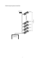
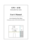
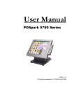
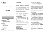
CODE
Scanner Console
User’s Manual
Ver 1.01
CODE ELECTRONIC CO., LTD.
CODE Flash 72 scanner console adopts international universal DMX512 digital format. It can control scanners
and other equipment with the same digital format. Its functions are compact. Its convenient and flexible
characteristics made it be handled very easily. Flash 72 is the best suit for various danceries, bar, and small art
show.
Technical specification
Output signal
DMX control channel amount
Control scanner amount
Maximum control channel amount of a scanner
Scanner chase
Maximum chase steps in a chase
Total chase steps
Chase step time
Chase gradual change ratio Cross
Display mode
DMX signal output connector
Other functions
Power supply
Size
Weight
DMX512
1-72
12
6
12
50
600
0.25-60s/step
0-100%
Backlight LCD screen and LED indicator
XLR-D3F
Data auto-saves, Values auto save for various
chase speed and gradual change
90-250VAC, 50-60Hz, 4W
482mm x 178mm x 55mm
2.55Kg
Cautions for safe use
Flash 72 scanner console must be connected to the earth line to ensure the safety.
When Flash 72 scanner console and scanners are working, don’t plug or pull out DMX512 data cable.
This will destroy the port electric components of the console.
Don’t splash any liquid to the scanner console. This will shatter the inside components of the console
and make functions failure.
Scanner console is precision electric equipment. Please pay attention to moisture-proof protection and
dust-proof protection. And please clean the control panel in schedule.
Installation of the console
Contents in Flash 72 scanner console package:
Flash 72 scanner console
Power adapter and DMX output (XLR-D3F)
User’s Manual
Flash 72 scanner console adopts international standard 19” 4U installing structure. It can be infixed in
operation board or directly installed in 19” shelf or cabinet.
When the power supply is connected, please check the voltage whether is in normal range. Otherwise,
steady voltage equipment may be needed.
-1-
Connect to scanner
According to DMX512 standard, 120Ω screened twist cable must be chosen as data cable between every
equipment. In practical engineering installation, if the whole length of the cable is short, the cable may be
replaced by high quality screened two-core microphone cable.
When the cable is joined to the XLR port, No. 1 connection of the XLR port is connected to the screen net of
the cable. Twist lines (distinguished by different colors) are connected to No. 2 and 3 connections. No. 3
connection is connected to the positive of signal. No. 2 connection is connected to the negative of signal.
Don’t connect a port in reverse.
In DMX signal transmission, a 120Ω terminal matching resister must be connected in the last equipment.
This can absorb the signal reflection at the end of cable. The operation is as following: connect a 120Ω
resister to No. 2 and 3 connections of XLR port and then plug the port to the last scanner (or the socket of
other equipment).
Distribution of DMX512 address
Flash 72 scanner console uses 1-72 channels of DMX512 to transmit the control signals to various scanners.
Each scanner is distributed with 8 control channels.
First DMX address of scanner
Switch bit of scanner address
Decimal Code
123456789
1
100000000
7
111000000
13
101100000
19
110010000
25
100110000
31
111110000
37
101001000
43
110101000
49
100011000
55
111011000
61
101111000
67
110000100
Scanner No
1
2
3
4
5
6
7
8
9
10
11
12
1# scanner
DMX
channels
1
6
2# scanner
7
3#scanner
12 13
11#scanner 12# scanner
61
18
12 scanners with 6 channels each
-2-
66 67
72
Sketch map of system connection
120 Ohm terminal
matching resister
4# scanner
DMX Addr: 19
3# scanner
DMX Addr: 13
2# scanner
DMX Addr: 7
1# scanner
DMX Addr: 1
Flash 72
Scanner Console
-3-
12 scanners
12# scanner
DMX Addr: 67
Introduction of the panel
No.
1
Name
Power
2
Blackout
3
Channels Level
4
Number keys
5
6
LCD
Speed
7
Cross
8
Delete
9
◄ Direction key
10
► Direction key
11
Program
Functions and purposes
Switch of AC power of the controller.
The key state is indicated by the red light above:
♦ Red light on, console is in standby state (blackout);
♦ Red light off, console is in running state.
In program state, move the slider can change the corresponding
channel value of specified scanner.
The number key group has multi functions:
♦ In program state, use it to choose editing program number and
scanner.
♦ In running state, use it to choose running program number.
Display the console state and setting values.
Adjust running speed of a chase step.
Adjust the gradual change cross time between chase steps.
0=slowest, 100%=fastest.
Used in program state:
♦ Press the key briefly to delete the current chase step.
♦ Press the key over 2 seconds to delete the current chase step
continually.
In program state, use it to check the chase step backwards.
In program state, use it to check the chase step forwards.
If the current step is the last one (with *), press the key to add a
step and copy the contents of the last step to new step.
♦ Press the key over 1 second, red light above blink. Console is
in program state;
♦ Press the key over 1 second again, red light off. Console is in
running state.
-4-
Rear of Flash 72
Information of LCD display
Display contents
[Standby]
[On line]
Select Chase
Chase:xxx
Step:[xx]
Detail explanation
Press Standby key, red light on. It is standby state (blackout).
Press Standby key, red light off. It is running state.
Please select program chase to run.
The number of current chase.
The number of current chase step.
Display when the Speed slider is adjusted. Xxx range: 000%-100%,
000%=slowest,100%=fastest.
Display when the Cross slider is adjusted. Xxx range: 000%-100%,
000%=slowest,100%=fastest.
Current chase has no content. It is empty.
After pressing Program key over 1 second to program state, please
select a program chase number.
The number of current editing program chase.
* indicates the step is the last one.
Speed [xxx%]
Cross [xxx%]
Step is empty!
==PROGRAM==
Select chase:
PROG CHASE: XXX
Step:[xxx]*
Note: xxx is number.
Control scanner running
1.
Just use ①, ⑤,⑥, ⑦ parts of panel to control scanner running.
2.
Press 1-12 number key to select the number of scanner program chase.
3.
If the program chase of corresponding number has not been edited, press the number key and the
green light is not on.
4.
Use Speed slider to control the running speed of current chase, the console will keep the running
speed of every chase.
5.
Use Cross slider to control the gradual change cross time, the console will keep the cross time of every
chase.
6.
0%=slowest,100%=fastest.
0%=slowest,100%=fastest.
Two states of Standby key:
♦
When red light is on, console is in standby state (blackout).
♦
When red light is off, console is in running state.
Flash 72 scanner console has data auto-save function. When the console is turned off or the power supply is
broken off, it can save the last running state. When it is turned on or the power supply is normal, it runs from
stop point.
-5-
Scanner chase edit
1.
Press Program key over 1 second, the console is in program state.
2.
Use number key to select editing chase number.
3.
Use ►, ◄ key change the current chase step. If the current step is the last one, it has a * on the
screen.
4.
Use number key to select editing scanner number.
5.
Adjust CH1-CH8 slider to set various channel value of scanner.
6.
Repeat 4-5 steps to set channel value of other scanner.
7.
Use ► key to next chase step. If the current step is the last one (with *), it copy the contents of current
step to the new one automatically.
Repeat 4-6 steps to edit other steps.
8.
Press Program key over 1 second, quit from the program state.
Repeat 1-8 steps to edit other chases.
-6-
Functions of ►, ◄ keys
They can only be used in program state.
1.
Use ►, ◄ key to check the light effect of edited chase step.
2.
Insert and copy functions of ► key (with example):
♦
If current chase has not been edited, LCD screen will display “Step is empty!” when the console
go into program state. Press ► key to insert a new step, the screen display “Step [001] *”. It
indicates the number of current step=001 and it is the last step.
♦
After setting various channel values of every scanner in“Step [001]”, press ► key. A new chase
step 002 is inserted and the screen display“Step [002] *”. It indicates that step 002 is the last one
and the contents of step 001 has been copied to step 002 automatically.
Functions of Delete key
The key can only be used in program state:
♦
Press the key briefly, the editing chase step is deleted.
♦
Press the key over 2 seconds, the current chase step is deleted quickly. When all the chase steps
are deleted, the current chase is empty.
Tips of program
♦
After finishing current program, quit from the program state. Then go into program state again to edit
another program.
♦
Pay attention to the use of ► key and understand how to use it correctly. Otherwise unwanted, useless
or black chase step is appended.
♦
A program just with one step can be edited to use as scanner fixed scene.
♦
In program state, Speed and Cross are not need to set. They are set directly in program running state
and saved automatically.
-7-
Sketch map of program operation
① Into program state
-----------------------------------------Press Program key over 1 sec.
② Select program No.
-----------------------------------------Use number key to select
program No.
③ Select chase step
-----------------------------------------Use <,> key to select chase step
④ Select scanner
-----------------------------------------Use number key to select scanner
⑥
⑤ Set channel level of scanner
⑦
-----------------------------------------Use CH1-Ch6 slider to set
channel level of scanner
No
Yse
Is another scanner set?
No
Is another chase step
set?
⑧ Quit from program state
-----------------------------------------Press Program key over 1 sec.
-8-
Yes
M E M O