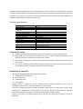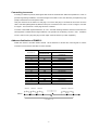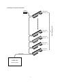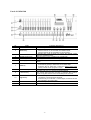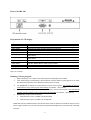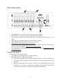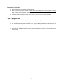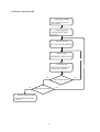
1
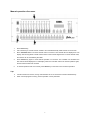
CODE
Scanner Controller
User’s Manual
Ver 1.03
CODE Electronic Co., Ltd.
Following the universal DMX512 protocol, CODE GOBO 200 scanner controller can control sixteen 12-channel
scanners or other equipment. Chase program and manual control of scanners can be performed at the same time.
Its functions are compact. Its convenient and flexible operation made it be handled very easily. GOBO 200 is
suitable for different ballroom, taproom and small show.
Technical specifications
Output signal
DMX channels
Control amount of scanners
Maximum control channel amount of
a scanner
Manual operation of scanner
Amount of chase programs
Maximum chase steps in a chase
Total chase steps
Range of chase speed
Ratio range of cross between steps
Display mode
Port of DMX output
Other functions
Power supply
Size
Weight
DMX512
1-192
16
12
16
50
580
0.25-60s/step
0-100%
LCD display and LED indicator
XLR-D3F
Auto save for every data when power off and auto save for
chase speed and cross ratio.
AC 90-240V,50-60Hz,4W
482mm x 178mm x 55mm
3Kg
Cautions for safety
GOBO 200 scanner controller must be connected to earth ground to ensure the safety of user.
When GOBO 200 and scanners are working, don’t plug in or pull out DMX512 data cable to avoid
destroying the electric components of the port in the controller.
Don’t splash any liquid to the controller to avoid destroying the electric components and the functions of
the controller.
The scanner controller is precision electric equipment. Please pay attention to moistureproof protection
and dustproof protection. And please clean the controller panel termly.
Installation of controller
Contents in the package of GOBO 200 scanner controller:
GOBO 200 scanner controller
1;
Power supply line
1;
Certification of QC
1;
User’s Manual
1.
Installing structure of GOBO 200 scanner controller follows international standard 19” 4U. It can be
embedded in operation board or directly installed in 19” shelf or cabinet.
The power of GOBO 200 scanner controller has steady voltage output in so wide range of power supply
voltage that it is adapted to the power supply of many countries. Before the power supply is connected,
please check whether the voltage is in normal range of GOBO 200 to ensure the safety.
When the fuse needs to be replaced, please use the fuse with the current capacity signed on the rear of
GOBO 200.
-1-
Connecting to scanner
According to DMX512 protocol, DMX signal cable must be screened twist cable with impedance of 120Ω. In
practical engineering installation, if the whole length of the cable is short, the cable may be replaced by high
quality screened two-core microphone cable.
User joins each end of the cable to a XLR plug. Foot 1of the XLR plug is connected to the screen net of the
cable. Twist lines (distinguished by different colors) are connected to foot 2 and 3. Foot 3 is signal + and foot
2 is signal -. Foot 2 and foot 3 of the plug cannot be confused.
To ensure correct DMX signal transmission, an 120Ω terminal matching resistance must be connected to the
last equipment to absorb terminal signal reflection. The operation is as following: connect a 120Ω resistance
to foot 2 and foot 3 of a plug then plug it to the output of the last scanner (or other equipment).
Address distribution of DMX512
GOBO 200 scanner controller utilizes channel 1-96 of DMX512 to transmit the control signals to various
scanners. Each scanner is fixed with 8 control channels.
First DMX address of scanner
Switch bit of scanner address
Decimal Code
123456789
1
100000000
13
101100000
25
100110000
37
101001000
49
100011000
61
101111000
73
101100100
85
101010100
97
100001100
109
101101100
121
100111100
133
101000010
145
100010010
157
101110010
169
100101010
181
101011010
Scanner No.
1
2
3
4
5
6
7
8
9
10
11
12
13
14
15
16
1#scanner
1
2#scanner
12 13
3#scanner
24 25
15#scanner 16#scanner
36
169
DMX ch.
12 ch.scanner x 16
-2-
180 181
192
Schematic of system connection
120Ω
Resistance
4# scanner
DMX addr: :37
3# scanner
DMX addr:
25
2# scanner
DMX addr:
13
1# scanner
DMX addr:
DMX Cable
GOBO 200
Scanner Console
-3-
1
12 ch. Scanner x 16
16# scanner
DMX addr: 181
Panel of GOBO 200
No.
1
2
3
4
5
6
7
8
9
10
11
12
Name
power switch
Functions and purposes
Switch of AC power of the controller.
The key state is indicated by LED as following:
blackout key
♦ When its LED is on, the controller is in blackout state;
♦ When its LED is off, the controller is in running state;
In program edit, move the slider can change the channel control
CH1~CH12 channel slider
value of a specified scanner.
manual operation key
When its LED is on, the controller is in manual state;
Number key 1~16
These keys are used to choose chase program and scanner.
Display the current state of the controller and various setting
LCD display
values.
Be used in program edit state:
♦ Press the key quickly to delete the current chase step.
delete key
♦ Press the key for more than 1 second to delete chase steps
quickly until the chase program is empty.
◄ Direction key
In program edit, use it to check chase steps backwards.
In program edit, use it to check chase steps forwards.
► Direction key
If the current step is the last one (with *), press the key to add a
step and copy the contents of the current step to the new one.
♦ Press the key for more than 1 second, its LED is on and the
controller is in chase program edit state;
program key
♦ Press the key for more than 1 second again, its LED is off and
the controller is in running state;
speed slider
Adjust chase speed, 0=slowest, 100%=fastest.
cross slider
Adjust cross time between steps, 0=slowest, 100%=fastest.
-4-
Rear of GOBO 200
Information of LCD display
Display contents
[BLACKOUT]
[On line]
Select Chase
Chase:xxx
Step:[xx]
Speed [xxx%]
Cross [xxx%]
Step is empty!
==PROGRAM==
Select chase:
PROG CHASE: XXX
Step:[xxx]*
illustration
When blackout key is pressed, its Led is on and the controller is in blackout state.
When blackout key is pressed, its Led is off and the controller is in running state.
Please choose chase program wanted to be performed.
Number xxx of the current chase program.
Number xx of the current chase step.
Display when speed slider is adjusted. xxx range: 000%-100%,000%=slowest,
100%=fastest.
Display when cross slider is adjusted. xxx range: 000%-100%,000%=slowest,
100%=fastest.
The current chase program has no content. It is empty.
After pressing program key for more than 1 second, the controller is in program
edit state. Please select a chase program number.
The number xxx of chase program being edited.
Use * to indicate the chase step is the last one.
Note: x is a number.
Running of chase program
1.
Press number key 1-16 to perform the chase program corresponding to the number.
2.
If the chase program corresponding to the number has not been edited, its green light is not on when
the number key is pressed. This indicates the chase program is empty.
3.
Use speed slider to change the running speed of current chase program. The controller will save the
speed values of every chase program automatically. 0%=slowest,100%=fastest.
4.
Use cross slider to change the cross time between steps of current chase program. The controller will
save the cross time values of every chase program automatically. 0%=slowest,100%=fastest.
5.
blackout key has two states as following:
♦
When its LED is on, the controller is in blackout state;
♦
When its LED is off, the controller is in running state.
GOBO 200 scanner controller has auto save function when power off. When the controller is turned off or the
power supply is broken off, it can save the last running state automatically and run from that state continually
next time.
-5-
Edit of chase program
1.
Press program key for more than 1 second to enter into program edit state.
2.
Use number key to choose the number of chase program want to be edited.
3.
Use ►, ◄ key to change the current chase step. If the current step is the last one, it has a * on the
screen.
4.
Use number key to choose the number of a scanner wanted to be edited.
5.
Move CH1-CH12 slider to set each channel value of the scanner.
6.
Repeat steps 4-5 to set channel values of other scanners.
7.
Use ► key to next chase step. If the current step is the last one (with *), it copy the contents of current
step to the new one automatically. Repeat steps 4-6 to edit other steps.
8.
Press program key for more than 1 second to quit from program edit state. Repeat steps 1-8 to edit
other chase programs.
Functions of ►, ◄ keys
They can be used just in program edit state.
1.
Use ►, ◄ key to check the lighting effect of edited chase step.
2.
Insert and copy functions of ► key (with example):
♦
If current chase program is empty, LCD display will display “Step [001] *” when the controller goes
into program edit state. This indicates that the number of the current chase step is 001 and it is
the last one.
♦
After every channel value of every scanner in“Step [001]”are set, press ► key to insert a new
chase step 002. “Step [002] *”is displayed on LCD display. It indicates that step 002 is the last
one and the contents of step 001 have been copied to step 002 automatically.
-6-
Functions of Delete key
♦
Press the key quickly to delete the current chase step.
♦
Press the key for more than 1 second to delete chase steps quickly until the chase program is empty.
When all chase steps are deleted, a chase program is an empty chase program.
♦
In manual operation state of a scanner, press the key to clear the record of manual operation.
Tips of program edit
♦
When the edit of current chase program is finished, quit from program edit state first, then enter into
this state again to edit another chase program.
♦
Pay attention and comprehend sufficiently to the usage of ► key. Otherwise unwanted, useless or
blackout chase step is inserted.
♦
A chase program just with one step can be edited as a fixed scanner scene.
♦
In program edit, speed and cross are not set. They are set directly in program running state and saved
automatically.
-7-
Schematic of program edit
① Into program edit state
-----------------------------------------Press Program key for more
than 1 second
② Choose program No.
-----------------------------------------Use number key to choose
program No.
③ Choose chase step
-----------------------------------------Use<>key to choose chase step.
④ Choose scanner
-----------------------------------------Use number key to choose scanner
⑥
⑤ Set channel value
-----------------------------------------Move CH1~CH12 slider to set
channel value of a scanner
No
Yes
Edit another scanner?
No
Yes
Edit another chase step?
⑧ Quit from program edit state
-----------------------------------------Press Program key more than
1 second.
-8-
⑦
Manual operation of scanner
1.
Press manual key;
2.
Use number key to choose scanner wanted to be controlled manually. Multi scanner can be chosen.
3.
Move CH1-CH12 slider to set each channel value of a scanner. Last channel value is displayed on LCD
display. After moving slider to make channel value of the scanner larger than the current channel value,
the scanner can be controlled by the slider.
4.
Press manual key again to cancel manual operation of a scanner. The controller can remember the
last channel values displayed on LCD display. When the controller enters into manual operation again,
the last channel values are resumed.
5.
In manual operation state of a scanner, press delete key to clear the record of manual operation.
♦
If multi scanners are chosen, moving channel slider can act on all chosen scanners simultaneously.
♦
When a chase program is running, manual operation can be performed.
Tips
9
MEMO
CODE Electronic Co., Ltd.
Address: 23 FenJiangBei Rd., Foshan, Guangdong, P. R. China.
Postcode: 528000
Tel: 86-757-82837500 / 82837511
Fax: 86-757-82837522
http://www.codelight.com E-mail: [email protected]