1
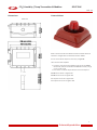
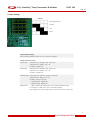
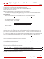
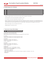
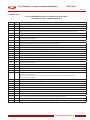
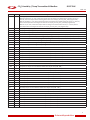
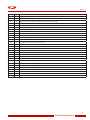
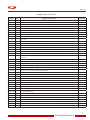
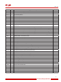
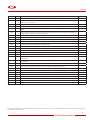
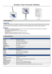
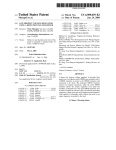
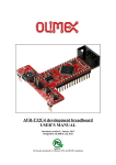
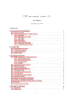
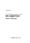
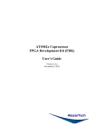
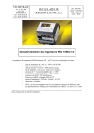
CO2/ Humidity / Temp Transmitter & Modbus
DCHT 24X
Feb. 14
Features:
-- High performance digital sensors and circuits ensure accurate
measurement and temperature compensation
-- Good long term stability and reliability
-- 100% field changeable sensors, no re-calibration needed
-- Multiple output signals selectable: 4-20mA, 0-5V or 0-10V
-- Display in degrees Fahrenheit or Celsius (connection to Modbus)
DCHT 24X
Applications:
Technical data:
CO2
Sensor
Dual Beam NDIR
Range
0-2,000 ppm
Output
RS485 and Analog Output (0-5V/0-10V/420mA)
Accuracy
±70 ppm or ±5% of reading
Relative Humidity
CO2 sensor with Humidity & Temperature transmitters are designed
for environment monitoring and controlling in industrial,
commercial and other buildings.
These transmitters can be used to monitor CO2 levels, air temperature and humidity in:
-- various industrial plants
-- clean rooms
Sensor
Capacitance polymer
Range
0~100% non condensing
-- labs
Output
4-20mA, 0-5V or 0-10V, RS 485
Accuracy
5% RH (25°C, 20~80% RH)
-- machine rooms
Hysteresis
< ±1% RH
-- offices
Response time
< 10s (25°C, in slow air)
-- commercial buildings
Drift
< ±0.5% RH / year
Temperature
Sensor
NTC 10K internal
Range
-40~150°C (-40~302°F)/transmitter
Output
4-20mA, 0-5V or 0-10V, RS 485
Accuracy
< ±0.5°C @ 25°C
-- airports
-- stations
-- libraries and stadiums.
General
Power
12 to 24Vac/dc ±10%
Current Output Load
< 500Ω
Display
LCD screen
Display Resolution
0.1°C, 0.1% RH
Temperature Limit
-30~70°C, 0~95% RH (Non condensing)
Plastic Housing
Flammability rating UL 94V0 file E194560
Alarm Connection
200 mA@12Vdc
Ordering Codes
DCHT 24X
CO2, RH+T, Modbus, 0-2,000ppm
Option
3,000, 5,000, 10,000ppm
1
Automatikprodukter
CO2/ Humidity / Temp Transmitter & Modbus
DCHT 24X
Feb. 14
Dimensions
External Alarm
DCHT 24X
When connected to the transmitteer this external alarm will sound
and flash a red light when the CO2 levels become “POOR”.
You can set the alarm setpoints in the meny using RS485.
There are two alarm setpoints:
1.Fair alarm: The alarm output will be turned on for the ALARM
ON seconds, then be turned off for ALARM OFF seconds, and go
out on on-off-on-off.
2.Poor alarm: The alarm output will be turned on and kept on.
ALARM ON can be set in register 162
ALARM OFF can be set in register 163
Fair setpoint can be set in register 165
Poor setpoint can be set in register 166
2
Automatikprodukter
CO2/ Humidity / Temp Transmitter & Modbus
DCHT 24X
Feb. 14
Features and Wiring Diagram
Captive Screws
(Will nor fall out)
Rubber Seal
IP65 Outdoor Rated
Hidden Mounting
Screws (type of 3)
Pluggable Connections
to Lid and Field Wiring
Outlet
jumpers
4-20mA
0-5V
0-10V
Removable Lid
RS485 Net
ModBus
Water tight or
1/2” EMT Wire Entry
Assembly and Wiring
Alarm connection (12Vdc/0V)
GND
GND
12 - 24Vac
Humidity Output (0~10V/5V/4~20mA)
Temperature Output (0~10V/5V/4~20mA)
CO2 Output (0~10V/5V/ 4~20mA)
GND
GND
RS485 Modbus Network
EMT Fitting
Waterproof fitting
8 mm wire dia
3
Automatikprodukter
CO2/ Humidity / Temp Transmitter & Modbus
DCHT 24X
Feb. 14
Jumper Settings
JUMPERS
CPU Range Indicator
4-20mA
0-5V
0-10V
Output Modbus Settings
Can auto detect hardware jumper sets, do not need to set registers
Voltage & Current Formula
0-10V output
Temperature (C) = (Voltage * 100 - offset) / 10
Temperature (F) = (DegC) * 9 / 5 + 32
Humidity = Voltage / 10
0-5V output
Temperature (C) = (Voltage * 100 - offset) / 20
Temperature (F) = (DegC) * 9 / 5 + 32
Humidity = Voltage / 20
4-20mA output Temperature (C) = ((Current – 4)/0.16) – offset/10
Temperature (F) = DegC * 9 / 5 + 32
Humidity = (Current – 4)/0.16
--- Temperature(F) : register 100
--- Temperature(C) : register 101
Applied for all
--- Offset : register 442, offset from zero C to adjust temperature range
for example 0 = 0-100C; 300 = -30 to +70C (Default setting)
where Voltage is the input voltage in Volts, and Current is in mA, ie 10 = 10ma
4
Automatikprodukter
CO2/ Humidity / Temp Transmitter & Modbus
DCHT 24X
Feb. 14
1. Humidity Sensor Calibration
Use a good humidity reference, let the room or cabinet stabilize for at least 30 minutes.
Your reference meter should be calibrated and up to date, meters can easily be out by 20% and more
from their stated accuracy from various factors.
Preferably use a cabinet or box around the sensor to be calibrated.
If you cannot use a cabinet, be sure all the windows and doors are closed for the duration of the test.
Setting low and high humidity values for multi point calibration procedures can be accomplished by
-- Using humidity reference bottles, these are often available on ebay or the google shopping site by searching “Humidity calibration”.
-- Here’s the link for google shopping: http://www.google.com/shopping?hl=en&tab=wf
Single point calibration:
-- Read the value from your meter, write this value to register 112 which is the current humidity reading Register.
112
Relative Humidity in Percentage
2 point Calibration:
-- Use a humidity reference bottle or humidity chamber
-- Set the humidity to a low value, usually around 30%.
-- Let the humidity stabilize for at least 30 minutes,
-- Read the value from your meter and write this value to Register 112
112
Relative Humidity in Percentage
-- Repeat this procedure at a higher humidity, usually around 70% and at least 10% greater than the first low value that you used for the
first point of calibration.
3 and up to 10 point Calibration:
-- Repeat the procedure of the two point calibration method, only use more calibration points, always writing to Register 112
-- Each reference humidity setting should be at least 10% away from the other calibration points.
If you need to repeat any of the calibration points, simply repeat the procedure. The sensor will take the new calibration point if the new
value is more than 5% away from previous calibration points. If its closer than 5%, the old values will be tossed out and the new ones incorporated into the calibration table.
You can switch from user calibration data to factory calibration data, back and forth by writing to register 378, value = 1 means the user table,
value = 0 means the factory table. Switching back and forth is possible, no data is lost by jumping from the user table or factory table.
117
Calibration table select. 0: factory data 1: user data
If the calibration procedure becomes muddled you can delete the user calibration points by writing 1 to register 112, all user calibration is
tossed out and the default factory values are restored to the user calibration table.
All calibration points are saved to non volatile memory and are not lost even for extended periods without power. Sensor elements can be
swapped from one unit to another and the calibration points will be automatically transferred along with the sensor element, the main display unit will handle sensor swapping automatically.
2. Temperature Sensor Calibration
Write current temperature to Reg101 for Fahrenheit or 102 for Celcius.
101
2
0~600
--
ROOM TEMPERATURE
reading in DegF. Can also write to this register for single point calibration.
102
2
0~600
--
ROOM TEMPERATURE
reading in DegC. Can also write to this register for single point calibration.
This operation will change the current temperature to user input value.
5
Automatikprodukter
CO2/ Humidity / Temp Transmitter & Modbus
DCHT 24X
Feb. 14
3. Temperature Current Output Calibration 4-20mA
367
Calibrate Temperature Output in 4-20mA mode
369
Output for current factory calibration
141
Temperature output current calibration offset value adjust value( 0 - 10% )
142
Temperature output current calibration offset value adjust value( 10% - 20% )
143
Temperature output current calibration offset value adjust value( 20% - 30% )
144
Temperature output current calibration offset value adjust value( 30% - 40% )
145
Temperature output current calibration offset value adjust value( 40% - 50% )
146
Temperature output current calibration offset value adjust value( 50% - 60% )
147
Temperature output current calibration offset value adjust value( 60% - 70% )
148
Temperature output current calibration offset value adjust value( 70%- 80% )
149
Temperature output current calibration offset value adjust value( 80% - 90%)
150
Temperature output current calibration offset value adjust value( 90% - 100%)
User can also calibrate each 10% percent output by manually change the reg141 to reg150
4. Humidity Current Output Calibration 4-20mA
151
Humidity output current calibration offset value adjust value( 0 - 10% )
152
Humidity output current calibration offset value adjust value( 10% - 20% )
153
Humidity output current calibration offset value adjust value( 20% - 30% )
154
Humidity output current calibration offset value adjust value( 30% - 40% )
155
Humidity output current calibration offset value adjust value( 40% - 50% )
156
Humidity output current calibration offset value adjust value( 50% - 60% )
157
Humidity output current calibration offset value adjust value( 60% - 70% )
158
Humidity output current calibration offset value adjust value( 70%- 80% )
159
Humidity output current calibration offset value adjust value( 80% - 90%)
160
Humidity output current calibration offset value adjust value( 90% - 100%)
User can also calibrate each 10% percent output by manually change the reg151 to reg160
5. CO2 Current Output Calibration 4-20mA
161
CO2 output current calibration offset value adjust value( 0 - 10% )
162
CO2 output current calibration offset value adjust value( 10% - 20% )
163
CO2 output current calibration offset value adjust value( 20% - 30% )
164
CO2 output current calibration offset value adjust value( 30% - 40% )
165
CO2 output current calibration offset value adjust value( 40% - 50% )
166
CO2 output current calibration offset value adjust value( 50% - 60% )
167
CO2 output current calibration offset value adjust value( 60% - 70% )
168
CO2 output current calibration offset value adjust value( 70%- 80% )
169
CO2 output current calibration offset value adjust value( 80% - 90%)
170
CO2 output current calibration offset value adjust value( 90% - 100%)
User can also calibrate each 10% percent output by manually changin the reg161 to reg170
6
Automatikprodukter
CO2/ Humidity / Temp Transmitter & Modbus
DCHT 24X
Feb. 14
6. Relative Registers for Calibration
370
Auto/Manual output calibrate set. 0 : default value 1 : user manual. Bit 0 :temperature bit1 :humidity
371
Temperature manual output value input, relative with register 370
372
Humidity manual output value input, relative with register 370
186
The factory default is 1. Temperature Transducer output range, 1=0-10V, 2=0-5V, 3=4-20mA
187
The factory default is 1. Humidity Transducer output range, 1=0-10V, 2=0-5V, 3=4-20mA
-- reg370: this register allows the user to set their own output value for temperature and humidity
-- bit 0: temperature manual output enable/disable, 0=disable 1=enable
-- bit 1: humidity manual output enable/disable, 0=disable 1=enable
-- Reg371: Temperature manual output value input, relative with register 370,for example, if output type is set to 0-10V(reg186 is set to 1),
and bit0 of reg370 is set to manual mode(reg371 is set to 1), if write 100 to reg371, current temperature output will be 1V, if 200,output
will be 2V, this function makes it possible for the user to test the hardware or generate their own voltage/current more easier
-- Reg372: just like reg371, but it’s for humidity manual output.
-- Reg186 & Reg187: see explanations above
7. Temperature Output Offset Settings
173
Temperature output offset, depending on sensor range
Firmware 340 och nedåt: 0-10V enligt 0-100°C
Firmware 341 och uppåt: 0-10V enligt -30-70°C
Lägg till register 442, customer can set the temperature range offset, base range is 0-100°C:
For example:
If register 442 set to 300, then current output range will be -30-70°C
If register 442 set to 100, then current output range will be -10-90°C
0-10V output:
Temperature (C) = (Voltage * 100 - offset) / 10
Temperature (F) = (Voltage * 100 – offset*9/5) / 10
Humidity = Voltage / 10
0-5V output:
Temperature (C) = (Voltage * 100 - offset) / 20
Temperature (F) = (Voltage * 100 – offset*9/5) / 20
Humidity = Voltage / 20
4-20mA output:
Temperature (C) = ((Current – 0.004)/0.00016) – offset/10
Temperature (F) = ((Current – 0.004)/0.00016) – offset*9/50
Humidity = (Current – 0.004)/0.00016
--- Temperature (F) : register 100
--- Temperature (C) : register 101
--- Offset : register 442, offset from zero C to adjust min max range, for example 0 = 0-100C, 300 = -30 to +70C
--- Voltage in Volt
--- Current in A
7
Automatikprodukter
CO2/ Humidity / Temp Transmitter & Modbus
DCHT 24X
Feb. 14
7. Register List
CO2 uses MODBUS protocol to communicate with others.
Following is a table of MODBUS Registers.
Address
Bytes
0 to 3
4
Serial Number - 4 byte value. Read-only
4 to 5
2
Software Version – 2 byte value. Read-only
6
1
ADDRESS. Modbus device address
7
1
Product Model. This is a read-only register that is used by the microcontroller to determine the product
8
1
Hardware Revision. This is a read-only register that is used by the microcontroller to determine the hardware rev.
9
1
PIC firmware version
10
1
PLUG_N_PLAY_ADDRESS, ‘plug n play’ address, used by the network master to resolve address conflicts.
See VC code for algorithms
15
1
Base address selection.0 = Protocol address,1 = PLC address.
16
1
Firmware Update Register, used to show the status of firmware updates
17 - 99
Register and Description
Blank, for future use
100
1
Temperature sensor select for display register 101&102. 0 = internal sensor. 1 = external sensor.
101
1
Select the temperature value display on LCD in DegC or DecF, 1 = F, 0 = C.
102
1
Internal temperature value of Celsius degree with 0.1 degree resolution
103
2
Internal temperature value of Fahrenheit degree with 0.1 degree resolution
104
2
External temperature value of Celsius degree with 0.1 degree resolution
105
2
External temperature value of Fahrenheit degree with 0.1 degree resolution
106
2
Relative humidity in percentage
107
2
Sensor frequency on time
108
1
Humidity sensor heating enable, 0 = disable, 1 = enable.
109
1
Set 1 to this register if there is a CO2 sensor inside the unit, else clear it to 0
110
2
The ppm of internal CO2 sensor. It will be 65535 when there is not internal CO2 sensor and display '***' on the
111-160
2
The ppm of external CO2 sensor.
161
1
”Alarm output and alarm state register:
Bit7: 0 = Auto, 1 = Manual.
Bit(1:0): 00 = alarm relay state is off, 01 = relay is pulsing in prealarm mode as defined by reg119, 10 =
continuous alarm, on always”
162
1
The ring on period of alarm in beeping/prealarm mode. (seconds, max = 20 seconds)
163
1
The ring off period of alarm in beeping/prealarm mode. (seconds, max = 20 seconds)
164
1
If the alarm is enabled, the unit will delay x seconds before turn on the beeper.
165
2
The pre_alarm ppm setpoint of internal CO2 sensor.
166
2
The continuous_alarm ppm setpoint of internal CO2 sensor.
167
2
The ppm offset for calibrating the internal CO2 sensor ppm.
168
2
Delta value for eliminating the pulse ppm value. The default value is 200.
169
1
Filter times, make the ppm value go smooth. The default value is 5.
170-219
2
*50 The pre_alarm ppm setpoint of external CO2 sensor. Support 50 external nodes.
220-269
2
*50 The continuous_alarm ppm setpoint of external CO2 sensor. Support 50 external nodes.
270-319
2
*50 The ppm offset for calibrating the external CO2 sensor ppm. Support 50 external nodes.
8
Automatikprodukter
CO2/ Humidity / Temp Transmitter & Modbus
DCHT 24X
Feb. 14
Address
Bytes
Register and Description
320
1
“Analog output auto or manual.
Bit0 for temperature, 0 = auto, means the output value according to the temperature read from sensor; 1 =
manual, means the output value according to the value set in output_manual_value_temp (register 321).
Bit1 for humidity, 0 = auto, means the output value according to the humidity read from sensor; 1 = manual,
means the output value according to the value set in output_manual_value_humidity (register 322).
Bit2 for co2, 0 = auto, means the output value according to the co2 read from sensor; 1 = manual, means
the output value according to the value set in output_manual_value_co2 (register 323).”
321
2
Output_manual_value_temp
322
2
Output_manual_value_humidity
323
2
Output_manual_value_co2
324
2
The minimum degree of temperature range corresponding to the temperature output(0-5V,0-10V,4-20mA)
325
2
The maximum degree of temperature range corresponding to the temperature output(0-5V,0-10V,4-20mA)
326
2
The minimum percent of humidity range corresponding to the humidity output(0-5V,0-10V,4-20mA)
327
2
The maximum percent of humidity range corresponding to the humidity output(0-5V,0-10V,4-20mA)
328
2
the minimum ppm of co2 range corresponding to the co2 output(0-5V,0-10V,4-20mA)
329
2
the maximum ppm of co2 range corresponding to the co2 output(0-5V,0-10V,4-20mA)
330
1
INFO_BYTE, TBD.
331
1
RS485 Baudrate, 0 = 9600, 1 = 19200
332
2
Temperature output current calibration offset value adjust value( 0 - 10% )
333
2
Temperature output current calibration offset value adjust value( 10% - 20% )
334
2
Temperature output current calibration offset value adjust value( 20% - 30% )
335
2
Temperature output current calibration offset value adjust value( 30% - 40% )
336
2
Temperature output current calibration offset value adjust value( 40% - 50% )
337
2
Temperature output current calibration offset value adjust value( 50% - 60% )
338
2
Temperature output current calibration offset value adjust value( 60% - 70% )
339
2
Temperature output current calibration offset value adjust value( 70%- 80% )
340
2
Temperature output current calibration offset value adjust value( 80% - 90%)
341
2
Temperature output current calibration offset value adjust value( 90% - 100%)
342
2
Humidity output current calibration offset value adjust value( 0 - 10% )
343
2
Humidity output current calibration offset value adjust value( 10% - 20% )
344
2
Humidity output current calibration offset value adjust value( 20% - 30% )
345
2
Humidity output current calibration offset value adjust value( 30% - 40% )
346
2
Humidity output current calibration offset value adjust value( 40% - 50% )
347
2
Humidity output current calibration offset value adjust value( 50% - 60% )
348
2
Humidity output current calibration offset value adjust value( 60% - 70% )
349
2
Humidity output current calibration offset value adjust value( 70% - 80% )
350
2
Humidity output current calibration offset value adjust value( 80%- 90% )
351
2
Humidity output current calibration offset value adjust value( 90% - 100%)
352
2
CO2 output current calibration offset value adjust value( 0 - 10% )
353
2
CO2 output current calibration offset value adjust value( 10% - 20% )
354
2
CO2 output current calibration offset value adjust value( 20% - 30% )
355
2
CO2 output current calibration offset value adjust value( 30% - 40% )
356
2
CO2 output current calibration offset value adjust value( 40% - 50% )
357
2
CO2 output current calibration offset value adjust value( 50% - 60% )
358
2
CO2 output current calibration offset value adjust value( 60% - 70% )
9
Automatikprodukter
Feb. 14
Adress
Byte
Register and beskrivning
359
2
CO2 output current calibration offset value adjust value( 70% - 80% )
360
2
CO2 output current calibration offset value adjust value( 80%- 90% )
361
2
CO2 output current calibration offset value adjust value( 90% - 100%)
362
1
RTC second, from 0 to 59.
363
1
RTC minute, from 0 to 59.
364
1
RTC hour, from 0 to 23.
365
1
RTC day, from 1 to 31.
366
1
RTC week, from 0 to 6, 0 = Sunday.
367
1
RTC month, from 1 to 12.
368
2
RTC year, from 0 to 99 (2000 to 2099).
369
1
The password to log in the menu system. 1=Enable. 0=Disable.
370
1
The first password character, from '0' to '9'.
371
1
The second password character, from '0' to '9'.
372
1
The third password character, from '0' to '9'.
373
1
The fouth password character, from '0' to '9'.
374
2
Menu block time. The menu will back to idle state after this seconds.
375
2
3Backlight keep time. The backlight will turn off after this seconds
376
1
External node plus&play. 1=Enable, 0=Disable.
377
1
Device number in the scan database, inlcude the master unit itself.
378
1
Set 1 to clear the scan database
379-383
5
First device of the database, the display unit takes it.
5 bytes: 1st = address, 2nd..5th = serial number
384-388
5
Second device of the database, the first external sensor.
5
5 bytes: 1st = address, 2nd..5th = serial number
If the address is 0 or 255, that means no device behind.
389-393
629
5
...
5
…
5
…
5
The end of the database
10
Automatikprodukter
Feb. 14
MODBUS Registers for CO2 Master
Address
Bytes
Register and Description
0..1
2
Lower 2 bytes of the serial number
2..3
2
Upper 2 bytes of the serial number
4
1
Firmware version lower byte. eg. FW version = 10.12, so lower byte = 12 AND high byte = 10. Fixed.
5
1
Firmware version upper byte. eg. FW version = 10.12, so lower byte = 12 AND high byte = 10. Fixed.
6
1
Modbus device address
7
1
Product ID, Fixed.
8
1
Hardware version
9
1
Spare
10
1
Spare
11
1
Time zone
12
1
Baudrate Setting: 0 = 9600bps, 1 = 19200bps
13
1
Day lighting switch, 0 =disable day lighting feature, 1= enable
14
1
Spare
15
1
Reset flash. The unit will clear all configs to zero if this register being set to 0x55 = 85
16
1
Firmware Update Register, used to show the status of firmware updates
17…90
1 * 74
91
1
Set 1 manual to write configurations to flash
92
1
Period of write configurations to flash if configurations changed without setting register to 1. counter
by second.
Comments
Spare
93…99
7
Reserved for future.
100 to 105
6
Reg100, MAC address, read only
106
1
Reg106, IP mode. 0=static IP; 1= DHCP
107 to 108
2
Reg107, upper two bytes of IP address
109 to 110
2
Reg109, lower two bytes of IP address
111 to 112
2
Reg111, right two bytes of SUBNET MASK address
113 to 114
2
Reg113, left two bytes of SUBNET MASK address
115 to 116
2
Reg115, right two bytes of GATEWAY address
117 to 118
2
Reg117, left two bytes of GATEWAY address
119
1
Reg119, 0, TCP server, (NO USE)
120
1
Reg120, listen port at TCP server mode
121
1
Ghost to reg 106
122 to 123
2
Ghost to reg 107 to 108
124 to 125
2
Ghost to reg 109 to 110
126 to 127
2
Ghost to reg 111 to 112
128 to 129
2
Ghost to reg 113 to 114
130 to 131
2
Ghost to reg 115 to 116
132 to 133
2
Ghost to reg 117 to 118
134
1
Ghost to reg 119
135
1
Ghost to reg 120
136
1
Write 1 to set the ghost settings to the system and start new settings, then clear the ghost registers.
137-171
40
Reserved
172
1
Scan command< =6 start scan>/LHN add
11
Automatikprodukter
Feb. 14
Address
Bytes
Register and Description
173
1
Subnet <add =1rs485 =2zigbee =4all> /LHN add
174
1
NTP command< =6, start ntp >/LHN add
175-178
4
Time Server0 ipaddress
179-182
4
Time Server1 ipaddress
183-186
4
Time Server2 ipaddress
187-190
4
Time Server3 ipaddress
191-194
4
Time Server4 ipaddress
195 -198
4
Time Server5 ipaddress
199
1
Time Sync result: 0-Fail 1-Sucessful
200
1
Temperature sensor selection, 0=external, 1=internal. Read only, it will be set to 1 if the humidity
module exists.
201
1
Select the unit of temperature to display on LCD. 0=degree Celsius, 1=degree Fahrenheit
202
2
The value of on board temperature sensor, the unit is degree Celsius. The resolution is 0.1 degree.
203
2
The value of on board temperature sensor, the unit is degree Fahrenheit. The resolution is 0.1 degree.
Opt
204
2
The value of external temperature sensor, the unit is degree Celsius. The resolution is 0.1 degree.
Save
205
2
The value of external temperature sensor, the unit is degree Fahrenheit. The resolution is 0.1 degree.
206
2
The temperature offset for calibrating the internal temperature. The resolution is 0.1 degree.
207
2
Relative humidity. The resolution is 0.1%
208
2
Read only. The real frequency read from the humidity module, unuse.
209
1
Read only. The number of the calibration table points.
210
1
Internal CO2 sensor selection. The value is 1 as default.
211
2
The CO2 ppm value of internal CO2 sensor.
212
2
The CO2 ppm offset for calibrating internal CO2 sensor.
213
2
The setpoint value of fair alarm for internal CO2 sensor.
214
2
The setpoint value of poor alarm for internal CO2 sensor.
215..468
2*254 The CO2 ppm value of the external CO2 sensors if there are/is CO2 nodes connect to it.
469..722
2*254 The CO2 ppm offset for calibrating external CO2 sensors.
723..976
2*254 The setpoint value of fair alarm for external CO2 sensors.
977..1230
2*254 The setpoint value of poor alarm for external CO2 sensors.
1231
2
The value to eliminate the pulse of the CO2 ppm.
1232
1
The filter to make the ppm value smoothly, it is 5 as default.
1233
1
Enable/Disable the password for the menu system operation. 0=Disable, 1=Enable.
1234
1
The first digital of the password. Should be from 0 to 9.
1235
1
The second digital of the password. Should be from 0 to 9.
1236
1
The third digital of the password. Should be from 0 to 9.
1237
1
The fourth digital of the password. Should be from 0 to 9.
1238
1
The century of the real time clock.
1239
1
The year of the real time clock.
1240
1
The month of the real time clock.
1241
1
The date of the real time clock.
1242
1
The weekday of the real time clock.
1243
1
The hour of the real time clock.
1244
1
The minute of the real time clock.
Comments
Save
12
Automatikprodukter
Feb. 14
Address
Bytes
Register and Description
1245
1
The secod of the real time clock.
1246
1
Alarm auto/manual control. Bit7: 0 = auto, 1 = manual; bit0:1 = pre_alarm; bit1: 1 = continuous_alarm;
bit(1:0): 00 = stop_ alarm
1247
1
The alarm output turn on time, <= 20 seconds.
1248
1
The alarm output turn off time, <= 20 seconds.
1249
1
Alarm output delay time. It delays the alarm output when the alarm is triggered. It is 5 seconds as
default.
1250
1
Analog output auto/manual control. Bit 0 directs to temperature output, Bit 1 directs to humidity output, Bit 2 directs to CO2 output. 0=Auto, 1=Manual.
1251
2
The manual value of temperature.
1252
2
The manual value of humidity.
1253
2
The manual value of CO2.
1254
1
Analog output mode, read only, select by jumper. 1=4-20mA, 2=0-5V, 3=0-10V
1255
2
The minimun value of temperature for analog output.
1256
2
The maximum value of temperature for analog output.
1257
2
The minimun value of humidity for analog output.
1258
2
The maximum value of humidity for analog output.
1259
2
The minimun value of CO2 for analog output.
1260
2
The maximum value of CO2 for analog output.
1261
1
The period for the menu system to stay at the submenu. It goes to the main menu when it expires in
the submenu.
1262
1
The period for the LCD backlight keep on. The backlight turns on when key is triggered, and turns off
the it expires.
1263
1
Enable/Disable the plug-and-play feature of the external nodes. 0=disalbe, 1=enable.
1264
1
The number of CO2 sensors connect to the unit, includes the internal CO2 sensor.
1265
1
Set 1 to reset the scan table.
1266..1270
1*5
Comments
The first CO2 node information. Normally it is the unit itself.
Register1266: the modbus ID of the CO2 sensor.
Register1267..1270: the serial number of the CO2 sensor.
1271..1275
1*5
The second CO2 node information. Normally, it is the first external CO2 node.
1276..1280
1*5
The third CO2 node information.
…
…
We cannot be held responsible errors in the manual/datasheet and reserve the right to correct any errors and to make product improvements, which may affect the accuracy of the
manual/datashet, without prior notice.
13
Automatikprodukter