1
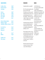
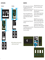
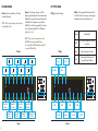
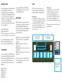
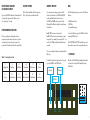
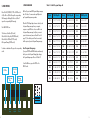
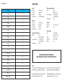
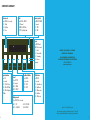
BIM User Manual
2
Safety warnings and recommendations
Do not eat BIM. Before using BIM, make sure to read all
the instructions below, and this User Manual. BIM has
some openings on its enclosure and 4 adhesive feet for
cooling purpose. To ensure sufficient cooling, do not
obstruct the openings and/or remove the adhesive feet.
BIM should be connected to the included AC adapter
or a power supply of the type described in this manual.
Do not place things on the top of the AC adapter which
could prevent normal cooling. If your BIM is unused
for a long period of time, disconnect the AC adapter
from the outlet. BIM, in combination with an external
amplification system or headphones, may generate a
high sound level, which could potentially damage your
ears. Do not operate BIM for a long period of time at
a high volume level. It’s safer to keep reasonable levels
and start with low volume. Do not expose BIM and its
AC adapter to rain, moisture, dust, sand or dirt. Do
not pour liquids into BIM. Never use or store BIM near
water, for example sea, swimming pool, bathtub, kitchen
or bathroom sink. BIM should be located away from
high temperatures (> 35 degrees C), for example direct
sunlight in an enclosed vehicle, radiators, heat registers,
stoves or other heat sources. Only clean BIM with a soft,
dry cloth. Do not apply any liquids or alcohol. Do not
apply excessive vibration forces to BIM, do not drop
it and always transport it in its original packaging or
in shock-absorbing material. Never climb on top of,
nor place heavy objects on BIM. Some parts of BIM
are fragile (such as the housing and some electronic
components), so dropping it might damage your BIM.
Repair work resulting from dropped BIM is not covered
by the normal warranty of the product. Do not leave
small children alone with BIM, and do not let them use
BIM unless they are capable of following all the rules
for the safe operation of BIM. Do not open (or modify
in any way) BIM or its AC adapter. There are no userserviceable parts inside. Refer all servicing to qualified
personnel only. If you think your BIM needs repair, you
can send us an e-mail at : [email protected].
Warranty
BIM is sold with one year full warranty. This warranty
covers all malfunctions that may occur from normal
use, and does not cover damage due to abuse,
faulty connections or operation under other than
specified conditions. Warranty is void when serial
number is unreadable, when the device is repaired by
unauthorized persons, opened, or tampered with in
any way, or if the product was not sold to the end user
through an authorized dealer or the OTO Machines
website. This warranty is limited to replacement or repair
of the product. The unit can only be returned for repair
after agreement from OTO Machines. Customer covers
shipping cost of faulty BIM to OTO Machines and OTO
Machines covers shipping cost back to customer.
Disposal
The trash can symbol indicates that your product must
be disposed of properly according to local laws and
regulations.
Warning on epilepsy
A very small percentage of individuals may experience
epileptic seizures or blackouts when exposed to certain
light patterns or flashing lights. If you have an epileptic
condition or have had seizures of any kind, consult your
physician before using BIM.
01
Table of contents
Presentation - Features
Front panel - Rear panel
Setup examples
Page 03
Page 04
Page 06
Parameters
Division - Range
FX Type - In Gain
Filters - Feedback
Offset - LFO
Page
Page
Page
Page
Page
Active mode - Tap Tempo destination
Display mode - Local mode
Feedback limiter - LFO Divisions - Freeze mode
Page 12
Page 13
Page 14
Presets - Recall - Save
Factory Presets
Memory protect
Page 15
Page 16
Page 17
MIDI
MIDI CC list
Page 17
Page 20
Specifications - Reset
Shortcuts summary
Page 21
Page 22
07
08
09
10
11
Presentation
Features
Congratulations and thank you for purchasing BIM !
• Up to 3276 milliseconds in stereo
• True 12-bit converters, analog limiter, companders,
filters and feedback path
• 4 delay types : Normal, Dual Head, Disto, Lo-Fi
• Delay high-pass filter : 20Hz, 100Hz, 250Hz or 500Hz
• Delay low-pass filter : 16kHz, 8kHz, 4kHz or 2kHz
• Feedback filters : flat, lo cut, hi cut or both
• LFO with 4 waveforms and 4 rate ranges
(from 0.025 Hz to 147 Hz)
• Tap Tempo with sub-division settings
• Freeze switch with normal or reverse play
• Delay input gain from 0 to +15dB
• 36 user presets
• MIDI input : BIM responds to MIDI Clock, CC and
Pgm Change
• 3 bypass modes : Relay, Spillover and Aux
• Nice and simple user interface via 16 white LEDs
• Rugged steel enclosure
• Neutrik® jack connectors
• Power supply included
BIM is a 12-bit stereo delay unit inspired by some studio
delay processors built in the early 80s.
These monophonic processors have been renowned for
the quality and musicality of their sound. The processing
was mainly analog (companders, limiters, low-pass
filters, feedback path,…), and the signal was converted
to digital just for the delay section, using 12-bit AD/DA
converters and some RAM memory chips.
The advantage of this technology is particularly obvious
when the sound is feedbacked many times through
the whole analog and 12-bit circuitry. You’ll hear
a sweet degradation and dark damping that the 100%
digital delay boxes can’t offer.
When we designed BIM, we wanted to create a unique,
modern and versatile effects processor based on this 80s
technology. We managed to mix the fabulous sound of
an old 12-bit digital delay with modern features such as
stereo processing, extra FXs, many user presets, MIDI
control, tap tempo, compact size… therefore BIM is the
best of both worlds !
BIM is the perfect companion for the musician, producer,
sound engineer or live performer who is looking for
a unique, warm and musical delay processor.
02
03
Front panel & Rear panel
01
03
f-back
delay
mix
02
06
04
rate
data
depth
08
05
09
07
active
01
02
03
04
05
06
07
08
09
10
11
12
-
DELAY. Sets the delay time
F-BACK. Sets the feedback amount
MIX. Mix between the dry and wet sound
DATA. Sets the selected parameter (cf p.7)
RATE. Sets the speed of the LFO for delay time modulation
DEPTH. Sets the amount of the LFO
ACTIVE. Turns the effect on or off (when it’s off, the delay is bypassed)
LEDs. Display the parameters, presets, midi settings and other infos
PRESET. Save and Recall presets
TAP. Tap tempo. Flashes in rhythm with the tempo
FUNCTION KEYS. Give access to the parameters (cf p.8 to 11)
FREEZE. Reads the current delay memory in loop
13
14
15
16
17
18
-
Power supply input. 15 Volts DC 0.5 Amps, center positive
MIDI In. Midi input
Out R. Right output. Unbalanced 1/4” jack
Out L. Left output. Unbalanced 1/4” jack
In R. Right input. Unbalanced 1/4” jack
In L/Mono. Left or mono input. Unbalanced 1/4” jack
preset
12
10
tap
division
range
fx type
in gain
filters
f-back
offset
lfo
freeze
out r
out l
in r
in l/mono
11
13
15 vdc
04
midi in
16
14
17
15
18
05
SETUP EXAMPLES
Parameters
2. Auxiliary
1. Instrument
Inputs
Outputs
Bim
Synthesizer
Outputs
Aux send
Outputs
Inputs
Aux Return
Bim has 10 parameters spread out over 4 function keys :
Division/Range, FX Type/In Gain, Filters/F-Back
and Offset/LFO. The first 2 function keys give you access
to 2 parameters, and the 2 others to 3 parameters.
Each press on the corresponding function key will
cycle through each available parameter. This selected
parameter will flash and can then be modified with
the DATA pot.
Bim
Mixer
To exit parameter selection press the function key until
the LEDs go off.
Main Outputs
3. Filters/F-Back. This function key has 3 parameters :
HPF, LPF and Feedback Filters.
HPF and LPF are displayed on the upper line and are
applied to the output of the delay. Feedback Filters
are displayed on the lower line.
4. Offset/LFO. This function key has 3 parameters :
Offset, LFO wave and LFO range. Offset is displayed
on the upper line and sets the time difference between
left and right delays. LFO wave and LFO range are
displayed on the lower line. LFO wave has 4 waveforms.
LFO range switches between 4 ranges of the LFO speed.
Mixer
Monitor Speakers
Stereo Line Inputs
Function Key Overview
1. Division/Range. Division sets the musical value of the
delay. Range sets the global delay memory size.
These two values are interlinked.
2. FX Type/In Gain. FX Type gives you access to 4
effects. In Gain sets the input gain of the delay.
Monitor Speakers
Main Outputs
Note : turn the MIX pot to its maximum position (right)
or set BIM in « Aux mode » (cf. page 12)
data
division
range
06
fx type
in gain
filters
f-back
offset
lfo
07
DIVISION/RANGE
FX TYPE/IN GAIN
Division. Sets the musical division of the delay
as related to the tempo.
Note : When you tap a new tempo, the quarter note
is automatically selected.
Range. Selects the range of memory used for the
delay, expressed in milliseconds. The min and max value
displayed here correspond to the min and max positions
of the DELAY pot. This parameter is associated with
the DELAY pot to set the tempo manually, but it can also
be used to divide or multiply the TAP or MIDI tempo
by a factor of 2, 4, 8....
In Gain. Sets the input gain of the delay from 0 dB to
+15 dB. Due to the built-in compressor, increasing gain
can add a nice character to the delayed sound.
FX Type. Selects the delay type.
Note : When you enter a new tempo tap or midi,
the range value may automatically change.
You cannot modify the RANGE parameter when BIM
is synced to MIDI Beat Clock.
Division
FX Type
.
From 8 to
25 ms
.
From 34 to
102 ms
From 17 to
51 ms
From 136 to
409 ms
From 68 to
204 ms
Range 08
3
From 546 to
1638 ms
From 273 to
819 ms
From 1092 to
3276 ms
Lo-Fi
Dual
3
Normal
Disto
0 dB
+4 dB
+ 2 dB
+8 dB
+6 dB
Normal
Standard Delay
Dual
Uses 2 different read positions for great
stereo effects
Disto
Adds soft distortion to the delay
Lo-Fi
Adds asymmetrical distortion and
low-pass filtering to the delay
+12 dB
+10 dB
+15 dB
In Gain 09
FILTERS/F-BACK
OFFSET/LFO
HPF. Selects the cutoff frequency of the delay high-pass filter.
LPF. Selects the cutoff frequency of the delay low-pass filter.
FB Filters. Selects which kind of filters are inserted
in the Feedback path (in addition to the delay filters).
0ffset. Sets the interval between the right and left delay
time. The right delay is fixed and the offset is expressed
as a percentage, so that « 50% » means that the left delay
is half the value of the right delay.
LFO Waveform. Selects the waveform of the LFO.
LFO Range. Selects the LFO frequency range of the
RATE pot.
Note : Offset is automatically set to 0% when the right
output is unplugged (mono out).
HPF
100 Hz
500 Hz
20 Hz
250 Hz
Flat
Hi Cut
Lo Cut
FB Filters 10
LPF
4 kHz
2 kHz
Lo Cut +
Hi Cut
Offset
8 kHz
50%
(ping - pong)
3%
16 kHz
0%
(no interval)
12%
Sinus
Square
Triangle
LFO Waveform
0.025 to
12 Hz
Sample
& Hold
25 to
73 Hz
12 to
37 Hz
50 to
147 Hz
LFO Range
11
ACTIVE mode
TAP Tempo destination
Display mode
LOCAL Mode (Tempo & Mix)
The ACTIVE switch has three Bypass
modes : Relay, Spillover and Aux.
The TAP tempo switch can be assigned to either the
Delay Time, the LFO Rate or both.
When no parameter is selected, you can choose what
the screen will display.
Each Preset contains its own Tempo (Tap or Time settings)
and Mix value. Sometimes it can be useful to load a preset
while keeping the current Tempo and Mix settings.
To change the Bypass mode, press and hold the ACTIVE
switch for at least 2 seconds. The ACTIVE switch
and one of the LEDs will flash to indicate the current
Bypass mode :
To change the TAP Tempo mode, press and hold the
TAP switch for at least 2 seconds. The TAP switch and
one of the following LEDs will flash to indicate the current
TAP Tempo destination :
To change the Display mode, press and hold the
DIVISION function key for at least 2 seconds.
The DIVISION function key and one of the following
LEDs will flash to indicate the current Display mode :
Led 1. Relay. When ACTIVE switch is off, inputs are
directly connected to the outputs via a relay, and
the electronics are completely bypassed. The tail of the
delay is muted when ACTIVE switch is off.
Led 2. Spillover. This is an electronic bypass, the tail
of the delay is not muted when the ACTIVE switch is off.
Led 3. Aux. The MIX pot sets the level of the delay
and the ACTIVE switch mutes the delay input when it’s off.
Led 1. Tap tempo is only assigned to Delay Time.
Led 2. Tap tempo is only assigned to LFO rate.
You can change the subdivision with the LFO Divisions
setting (cf. page 14).
Led 3. Tap tempo is assigned to both Delay Time
and LFO Rate.
Led 1. OFF mode. The screen will display nothing.
Led 2. VU-METER mode. The 16 LEDs act as a VU
meter and display the delay input level (the upper line
for the left input, the lower line for the right input).
Led 3. LFO mode. The 16 LEDs will move at the LFO rate.
Led 4. PRESET mode. The 16 LEDs show the current
preset and bank number.
You can change the bypass mode with the DATA pot.
To exit the ACTIVE settings, wait for 10 seconds or press
the ACTIVE switch.
You can change this destination with the DATA pot.
To exit the TAP Tempo settings, wait for 10 seconds
or press the TAP switch.
You can change the Display mode with the DATA pot.
To exit the Display mode settings, wait for 10 seconds
or press the DIVISION function key.
To change the Local mode, press and hold the FX TYPE
function key for at least 2 seconds. The FX TYPE function
key and one of the following LEDs will flash to indicate
the current Local mode :
Led 1. PRESET mode. The Tempo and Mix values
are loaded from the preset.
Led 2. Local mode. The Tempo and Mix values from
the loaded preset are ignored and the current Tempo
and Mix values are used.
You can change the Local mode with the DATA pot.
To exit the Local mode settings, wait for 10 seconds
or press the FX TYPE function key.
NOTE : When BIM is switched off, inputs are directly
connected to the outputs via the relay.
active
12
tap
division
fx type
13
Feedback Limiter
Because of its high dynamic circuitry, BIM automatically
prevents the feedback to reach self-oscillation.
You can bypass this protection, but be aware that the
self-oscillation can lead to a high level when the F-BACK
pot is set to its maximum position. To deactivate the
Feedback limiter, press and hold the FILTERS function key
for at least 2 seconds. The FILTERS function
key and one of the following LEDs will flash to indicate
the current Feedback mode :
Led 1. Feedback limiter ON.
Led 2. Feedback limiter OFF.
NOTE : This setting can lead to excessive feedback level
when you turn the F-BACK pot to its maximum position !
You can turn the Feedback limiter on or off with the
DATA pot. To exit the Feedback limiter settings,
wait for 10 seconds or press the FILTERS function key.
LFO Divisions
You can set the subdivisions for the LFO Rate when TAP
tempo is assigned to the LFO Rate. To change the LFO
Divisions, press and hold the OFFSET function key for at
least 2 seconds. The OFFSET function key and one
of the following LEDs will flash to indicate the current
LFO Division :
Led
Led
Led
Led
Led
14
PRESET
You can change the LFO Divisions with the DATA pot.
To exit the LFO Divisions settings, wait for 10 seconds
or press the OFFSET function key.
Freeze mode
The FREEZE switch can be set to operate in either Latch
or Momentary mode. To change the Freeze mode, press
and hold the FREEZE and the OFFSET function keys
simultaneously for at least 2 seconds. The FREEZE switch
and one of the following LEDs will flash to indicate
the current Freeze mode :
Led 1. Latch. Freeze is on when you press the freeze
switch. Freeze turns off when you press the freeze
switch again.
Led 2. Reverse Latch. Same as 1 but the Freeze
is played in reverse.
Led 3. Momentary. Freeze is only on when you depress
the FREEZE switch.
Led 4. Reverse Momentary. Same as 3 but the Freeze is
played in reverse.
You can now change the Freeze mode with the DATA pot.
To exit the Freeze mode settings, wait for 10 seconds
or press the FREEZE switch.
BIM has 36 presets; 6 banks of 6 presets each.
The upper line of LEDs (1 to 6) indicates the bank.
The lower line of LEDs (9 to 14) indicates the preset.
Recall a Preset
Press the Preset switch. The Preset switch lights up
and one of the upper line LEDs blinks. Press one of the
6 switches (from TAP to FREEZE) to select a bank.
Then one of the lower line LEDs blinks. Press one of
the 6 switches (from TAP to FREEZE) to select a preset.
Your preset is loaded.
These 6 LEDs indicate
the bank number
Save a preset
Press the Preset switch for 2 seconds. The Preset
switch flashes to indicate you are in Save mode.
One of the upper line LEDs blinks. Press one of
the 6 switches (from TAP to FREEZE) to select a bank.
Then one of the lower line LEDs blinks. Press one
of the 6 switches (from TAP to FREEZE) to select a preset.
All the parameters and pot positions are now saved
in the selected preset.
These 6 LEDs indicate
the preset number
1
2
3
4
5
6
tap
division
range
fx type
in gain
filters
f-back
offset
lfo
freeze
Use these 6 switches
to select the bank
and the preset
1. Sixteenth note
2. Eighth note
3. Quarter note
4. Half note
5. Whole note
15
Exit without loading
or saving a preset
If you press the PRESET switch before selecting the bank
or the preset, the preset won’t be loaded or saved.
You can also wait 10 seconds.
Factory presets
Memory protect
MIDI
The first 2 banks are filled with 12 factory presets.
These 12 factory presets are listed on table 1.
You can prevent overwriting your presets with the
Memory Protect function. Press PRESET and FREEZE
switches and hold them for at least 2 seconds.
The PRESET and FREEZE switches, and one of the
following LEDs will flash to indicate the current Memory
Protect mode :
The MIDI settings menu gives you access to the following
functions :
Led 1. OFF The memory is not protected.
Led 2. ON The memory is protected and you cannot
save presets. If you attempt to save a preset, LEDs 1 to 6
and 9 to 14 will flash briefly to indicate that memory is
protected.
To access the MIDI menu, press the ACTIVE switch while
pressing the PRESET switch.
POTENTIOMETERS POSITION
Once you recall a preset, the physical position of
a pot may not be the same as in the preset. To prevent
a sudden jump of volume when you turn a pot, the
preset value will reach the pot value with a smooth fade.
You can now change the Memory Protect mode with the
DATA pot.
Table 1 : Factory Presets list
1.1
The Nymph Echo
1.2
Dark Slap
1.3
Psychlotron
1.4
Faux Spring
1.5
Dust Memories
1.6
Vibroto
To exit the Memory Protect setting, wait for 10 seconds
or press the FREEZE or the PRESET switch.
2.2
Moving Resonator
2.3
Tunneling
2.4
Short and Sweet
2.5
Dirty Repeats
2.6
Seasickness
1. CHANNEL
One of the 16 LEDs will flash and display which channel
is selected. You can select a MIDI channel by turning
the DATA pot.
Midi Filters
tap
16
The TAP, DIVISION and FX TYPE keys flash. Press any of
these switches to access to the corresponding sub-menu.
PGM map
Channel
2.1
I See Icy
• MIDI Channel selection
• MIDI Filters
• Program Change map
division
range
fx type
in gain
17
2. MIDI FILTERS
3. PGM CHANGE MAP
One of the TAP, DIVISION, FX TYPE or FILTERS switch
is lit (the filter is off, BIM will accept the corresponding
MIDI message) or flashing (the filter is on, BIM will
ignore the corresponding MIDI message).
BIM has 36 presets and MIDI Program Change messages
have 128 values. You can associate any BIM preset to
any Program Change message number.
The 4 MIDI FILTERS are :
1. Continuous Controllers (TAP switch)
2. Beat Clock to Delay Time (DIVISION switch)
3. Beat Clock to LFO Rate (FX TYPE switch)
4. Program Change (FILTERS switch)
To activate or deactivate a filter, press the corresponding
switch.
When the PGM Change Map sub-menu is selected, send
a Program Change message from your computer,
sequencer or any MIDI device. As soon as BIM receive
a Program Change message, it will give you access to
a preset selection menu (same as « Recall a Preset » cf
page 15). The selected preset will now be associated
with the previously received Program Change message.
Reset Program Change map
If you press OFFSET and FREEZE switches simultaneously
while you are in the Program Change Map sub-menu,
the Program Change map will be reset (cf Table 2).
To exit the MIDI menu, press the ACTIVE or the
PRESET switch.
Clock to lfo
filter
CC filter
Clock to time
filter
tap
18
division
range
Program
change filter
fx type
in gain
Table 2 : Default Program Change list
Preset
PGM Chge Nr
Preset
PGM Chge Nr
Preset
PGM Chge Nr
1.1
1 - 37 - 73 - 109
3.1
13 - 49 - 85 - 121
5.1
25 - 61 - 97
1.2
2 - 38 - 74 - 110
3.2
14 - 50 - 86 - 122
5.2
26 - 62 - 98
1.3
3 - 39 - 75 - 111
3.3
15 - 51 - 87 - 123
5.3
27 - 63 - 99
1.4
4 - 40 - 76 - 112
3.4
16 - 52 - 88 - 124
5.4
28 - 64 - 100
1.5
5 - 41 - 77 - 113
3.5
17 - 53 - 89 - 125
5.5
29 - 65 - 101
1.6
6 - 42 - 78 - 114
3.6
18 - 54 - 90 - 126
5.6
30 - 66 - 102
2.1
7 - 43 - 79 - 115
4.1
19 - 55 - 91 - 127
6.1
31 - 67 - 103
2.2
8 - 44 - 80 - 116
4.2
20 - 56 - 92 - 128
6.2
32 - 68 - 104
2.3
9 - 45 - 81 - 117
4.3
21 - 57 - 93
6.3
33 - 69 - 105
2.4
10 - 46 - 82 - 118
4.4
22 - 58 - 94
6.4
34 - 70 - 106
2.5
11 - 47 - 83 - 119
4.5
23 - 59 - 95
6.5
35 - 71 - 107
2.6
12 - 48 - 84 - 120
4.6
24 - 60 - 96
6.6
36 - 72 - 108
filters
f-back
19
Specifications
Table 3 : MIDI CC list
20
Param
CC
Delay
12
Feedback
13
Mix
14
LFO Rate
15
LFO Depth
16
Active
17
Division
18
Range
19
FX Type
20
In Gain
21
HPF
22
LPF
23
Feedback Filters
24
Offset
25
LFO Wave
26
LFO Range
27
Freeze
28
Freeze Reverse
29
LFO Division
30
LFO Phase Reset
31
Inputs
Connectors :
Input type :
Impedance :
Max input level :
1/4” phone jacks
single ended
1 MOhm
+20 dBu (@1% THD+N)
Outputs
Connectors :
Output type :
Impedance :
Max output level :
1/4” phone jacks
single ended
100 Ohm
+20 dBu
Dry signal specifications
THD+N :
0.007 %
(20Hz - 20kHz, 0dBu)
Frequency response :
- 0.16 dBu @ 20Hz
- 0.23 dBu @ 20kHz
Dynamic range :
106 dB
Wet signal specifications
THD :0.089 %
(@1kHz, 0dBu)
Frequency response :
- 0.48 dBu @ 20Hz
- 3.00 dBu @ 15kHz
Dynamic range :
93 dB
General
Dimensions :
Weight :
145 x 145 x 65 mm
762 g
Power supply
Input :
Output :
Dimensions :
Weight :
100 to 240 VAC,
50 to 60 Hz, 0.6 Amp
+15 VDC, 1 Amp
74 x 43 x 35 mm
165 g
Due to continuous product improvement,
these specifications are subject to change without notice.
Reset
If you want to restore the default System settings, power
up BIM while pressing the ACTIVE and TAP switches.
If you want to restore the 12 Factory Presets, power up
BIM while pressing the PRESET and FREEZE switches.
The ACTIVE and TAP switches are lit and the 16 LEDs
will display a little animation for 3 seconds.
The PRESET and FREEZE switches are lit and the 16 LEDs
will display a little animation for 10 seconds.
21
SHORTCURTS SUMMARY
Active mode
Press ACTIVE for 2 seconds :
LED 1 : Relay
LED 2 : Spillover
LED 3 : Aux
Midi
Press ACTIVE + PRESET :
TAP : Channel
DIVISION : MIDI Filters
FX TYPE : Pgm Chge Map
preset
active
tap
Memory protect
Press PRESET + FREEZE
for 2 seconds :
LED 1 : OFF
LED 2 : ON
division
range
Tap destination
Press TAP
for 2 seconds :
LED 1 : TAP to Delay
LED 2 : TAP to LFO Rate
LED 3 : TAP to Delay and
LFO Rate
fx type
in gain
filters
f-back
Local
Press FX TYPE
for 2 seconds :
LED 1 : LOCAL
LED 2 : PRESET
offset
lfo
freeze
Feedback limiter
Press FILTERS
for 2 seconds :
LED 1 : ON
LED 2 : OFF
Display mode
Press DIVISION for 2 seconds :
LED 1 : OFF
LED 2 : VU-METER
LED 3 : LFO RATE
LED 4 : PRESET
Freeze.
Press OFFSET and
FREEZE for 2 seconds :
LED 1 : Latch
LED 2 : Reverse Latch
LED 3 : Momentary
LED 4 : Reverse
Momentary
Artwork : H5 (P. Manas & L. Houplain).
Illustrations : Pierre Manas.
BIM - User Manual OTO MACHINES SARL
27 Boulevard Saint Martin, 75003 PARIS FRANCE
+33 (0)1 75 50 61 04
www.otomachines.com
Lfo divisions
Press OFFSET
for 2 seconds :
LED 1 : Sixteenth note
LED 2 : Eighth note
LED 3 : Quarter note
LED 4 : Half note
LED 5 : Whole note
Copyright © 2015 Oto Machines SARL. All rights reserved.
No part of this manual may be reproduced in any form without the written permission of OTO Machine SARL.
Product features, specifications, availability and informations in this manual are subject to change without notice.
22
23
Tested to Comply with FCC Standards for office use. This device complies with Part 15 of the FCC Rules.
Operation is subject to the following two conditions :
(1) This device may not cause harmful interference and
(2) this device must accept any interference received, including interference that may cause undesired operation.
24