1
Premiere®
PC Configuration Manual
Part Number: 8-700218-010
Revision Level:
A0
Revision Date:
10/14/92
Chapter 1
Introduction and Assistance
This manual provides information on the installation and operating
procedures for the Premiere Configuration software.
Manual Organization
This manual contains information about installing and using the
Premiere Configuration Software. It contains the following chapters
plus and index:
Introduction (chapter 1) - tells you about the organization of this
manual and explains the typographical conventions used. In
addition, it contains a glossary of terms used in this manual, and tells
you how to get technical help if necessary
Navigating Windows (chapter 2) - tells you the basics of navigating
through programs written to run under Microsoft Windows.
Installation (chapter 3) - tells you how to install and start up the
software.
Reference (chapter 4) - tells you what each of the menus, screens,
and dialog boxes do. This chapter is organised alphabetically by the
name of the screen or dialog box.
Tutorial (chapter 5) - takes you through actually recording a set-up
for a Premiere system.
Conventions
b
(keycap image) shows keyboard keys. Keys may also be
shown in small caps bold (e.g., RETURN) when used in text.
OK
Helvetica bold text) shows the text of a control you should use
with a mouse (e.g., "click on OK"). All layers of a menu selection are
shown in a single entry; with menu levels separated by vertical bar
(e.g., "choose FileOpen").
ON
(all capital Times text) shows the status of a function or
switch, as in "Turn the switch ON."
Introduction and Assistance
Page 1
Glossary of Terms
The following terminology is used throughout this manual for
consistency. Please also refer to General Terminology in the
Navigating Windows chapter for terms specific to the Windows
environment, and to Commands in the Reference chapter for
definitions of specific Premiere commands.
Astronomical Time Clock The Premiere Processor has an internal clock that keeps track of both
time and date for use with automatic events programming. The events
can be programmed to occur at a specific time and date and also at
sunset or sunrise. The processor can calculate these varying times
throughout the year from knowing the latitude of the installation and
the sunrise time entered on the day of installation.
Cleanup
One of the 128 presets available per room. This preset lets you
assign the appropriate lighting channels for cleanup purposes, and
automatically fades out after one hour. Channels are assigned to the
preset during system configuration.
Channel
An arbitrary group of one or more dimmers controlled as a fixed
group. The allocation of dimmers to channels is called "Patching".
System patching is accomplished through the Premiere Configuration
Program.
Configuration Software
Premiere offers the ability to customise pushbuttons and faders on
control stations to perform different functions at any time. The
configuration software is used to define the number of rooms,
channels, and stations so that the system meets the requirements of
a specific installation. It can also be used to assign any one of over 80
functions to pushbuttons or faders on each control stations.
Delay Time
Delay Time is the elapsed time between selecting a preset to the
beginning of the preset fade. You can set the delay time for each
preset to a value between 0.1 seconds and 9 hours (inclusive) during
system configuration. You can change this value later from a 2200 or
2300 control station. Delay times between 0.1 seconds and 30
minutes can be set in 0.1-second increments. Delay times between
30 minutes and 9 hours, it can be set in 1 second increments.
Fade Time
The programmed time for fading from one set of light levels to
another. You can set the fade time for each preset to a value between
0.1 seconds to 9 hours (inclusive) during system configuration. You
can change this value later from a 2200 or 2300 control station. Fade
times between 0.1 seconds and 30 minutes can be set in 0.1-second
increments. Fade times between 30 minutes and 9 hours can be set
in 1 second increments.
Introduction and Assistance
Page 2
Hold Time
The programmed time that presets wait after completion before
moving automatically to the next preset. You can set the hold time for
each preset to a value between 0.1 seconds and 9 hours (inclusive)
during system configuration. You can change this value later from a
2200 or 2300 control station. Hold times between 0.1 seconds and 30
minutes can be set in 0.1-second increments. Hold times between 30
minutes and 9 hours can be set in 1 second increments. You can use
hold time to program a series of automatic fades or loops.
Level
The level of an individual channel, expressed as a percentage (i.e.,
00-99).
Link
A function that lets you connect divisible rooms so that control
stations within each of the combined rooms' control the lighting levels
over the entire combined area.
Lower Limit
The Lower Limit sets a floor on actual dimmer output. As you control
a channel the signal to the dimmers goes from FULL to ZERO. The
dimmer tracks the control until it reaches its Lower Limit and will not
fade any lower. You can use Lower Limit on a dimmer if you want
lights to remain on at a low level.
Scale
A scaling factor, which can be applied, to a dimmer to change its
dimming characteristics.
Preset
A pre-defined arrangement of intensities for a group of channels that
is stored in memory for recall when required.
Template
A set of definitions for the functions of control station buttons. Each
control station can have 16 templates, which lets you define 16
completely different functions for each pushbutton and fader. The
most common use for multiple templates is to provide additional
"pages" of presets.
Toggle
An alternate action pushbutton.
Upper Limit
The upper limit sets an actual ceiling on the dimmer output. As you
control a channel the signal to the dimmers goes from ZERO to FULL.
The dimmer tracks the control until it reaches its upper limit and will
not fade any higher. You can use Upper Limit on a dimmer to make
sure that it never exceeds a particular intensity.
Introduction and Assistance
Page 3
Technical Assistance
The Premiere Configuration Software is designed for easy
configuration of Premiere Systems using a standard MS/PC-DOS
compatible computer with a 3.5" floppy disk drive. This software runs
under Microsoft Windows (ver. 3.0 or later) or Windows 95.
Problems
If you have problems installing or operating this software, please
contact Strand Lighting Field Service at the office serving your area.
Strand Lighting will issue an RGA (Return Goods Authorisation)
before the return of any defective materials. This allows tracking of
returned equipment, and speeds its return to you.
Technical Questions
For technical questions regarding setup or operation of this software
please contact the Strand Lighting Field Service office serving your
area.
Parts Purchases
For purchase of spare parts or documentation please contact the
Strand Lighting office serving your area.
Comments and
Suggestions
For comments regarding equipment functions and/or possible
improvements, or for comments on this manual, please call or write to
the Marketing Manager at the Strand Lighting office serving your
area.
Addresses
Addresses for all of the Strand Lighting offices are shown on the
reverse side of the manual title sheet.
Introduction and Assistance
Page 4
Chapter
2
Navigating in Windows
Before you start using the Premiere Configuration software, you
should be familiar with your computer and its user's manual. You
need to know how to turn the computer on, which disk drive is
drive A, and what keys you press to reset, or "boot", your
computer.
Although you should also be generally familiar with Windows and
how to navigate in Windows programs, this chapter provides a
basic review and shows the terminology that will be used in this
manual.
General
Terminology
The following terminology is used throughout this manual, and is
generally considered standard when working with graphical user
interfaces such as Windows. Additional terms are defined under
Parts of a Window and Dialog Boxes later in this chapter
Choose
means to select an item from a menu. This usually involves two
levels of selection, since you first have to click on the main menu
item and then click on the item in the drop down menu. In this
manual, each level of menu is separated from the next with a
vertical bar (e.g., "choose System Patch").
Click on
means to position your cursor on top of the designated item and
pres s and release the left mouse button once (e.g. ... and click on
OK. ").
Directory
A collection of computer flies (programs and data) that are stored
at the same location on a disk. The name of the directory identifies
its location.
Double-click on
means to position your cursor on top of the designated item and
press and release the left mouse button twice in quick succession.
(e.g., ... and double-click on the item you wish to choose from the
list). If the clicking occurs within the time set in your Windows
Control Panel, Windows will interpret the two clicks as a single
gesture.
Drag
means to press the left mouse button and move the mouse while
keeping the mouse button pressed. When the desired action is
completed you release the mouse button. Drag refers to an action
sequence (mouse down, mouse move, mouse up), such as "Drag
the button in the scroll bar..."
Navigating in Windows
Page 5
Edit
means to modify an entry using standard Windows text editing
techniques. See Text Editing later in this chapter for more details
about how to edit text in Windows.
Point
To move the mouse until the tip of the pointer rests on the item of
choice.
Right click on
means to position your cursor on top of the designated item and
press and release the right mouse button once.
Scroll
means to scroll a list by dragging the box in the Scroll Bar, clicking
on the scroll arrows, or using i and k on your keyboard. See
Scrolling a List or Document later in this chapter for more details
on scrolling.
Window
A rectangular area that contains a software application or a
document file.
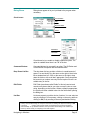
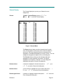
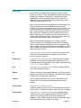
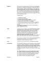
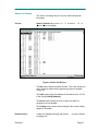
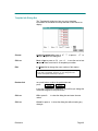
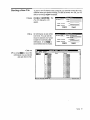
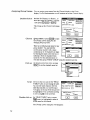
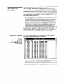
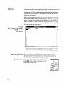
Parts of a Window
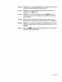
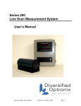
The Premiere Configuration Software screen consists of the key
components shown in figure 1.
Close Button
System Menu Button
Title Bar
Minimize / Maximize
Menu Bar
Dialog Box
Scroll Bar
Figure 1 - Parts of a Window
The access status indicator is unique to the Premiere Configuration Software and shows the
current access status of the Premiere Configuration software.
Dialog Box
Navigating in Windows
A dialog box is a temporary window that appears in response to
some action of yours and requires you so select or fill in items.
Components of dialog boxes are shown below. A description of
dialog box components appears below.
Page 6
System Menu
The System Menu provides a menu that lets you control some
aspects of the window, including exiting from the window. Click on
the System Menu button to see the menu. Double-click on the
System Menu button to exit from the program or window.
For instance, press a
+ F to see the File Menu
Menu Bar
The Menu Bar contains the top level menu items. You
can access the menus for the top-level items by clicking on the
item or by holding a and pressing the letter that is underlined in
the menu item.
Scroll Bar
Scroll bars can appear in the horizontal or vertical plane
of the window, or in both places. They indicate that there is more
of the window than can be shown on the screen. To move the
scroll bar, click on the appropriate arrow for small movements or
drag the button in the scroll bar to the required position.
Sizing Buttons
The sizing buttons in the upper right hand corner of a
window let you change a windows size or shape, i.e. maximize or
minimize the window.
Click on
this to iconize the window. The Window will be
made into a button and placed on the taskbar. To restore an icon
into a window (make it the size it was before it was iconized),
double-click on the icon.
Click on
this to "maximize' the window (make the window
fill your entire screen). The up arrow will change to a doubleended arrow to show that the window is maximized. You can then
click on the down arrow to iconize the window, or click on the
up/down arrow to restore the window (make it the size it was
before it was maximized).
Title Bar
The Title Bar shows the name of the program and the
current file. It changes color (along with the window border) to
show whether the window is active or not. You can reposition the
entire window by dragging the Title Bar.
Window Border
The window border lets you easily distinguish the edge of
the current window. It changes color (along with the Title Bar) to
show whether the window is active or not. You can also resize many
windows by pointing to the border, clicking on the left mouse button,
and dragging the mouse to move the border.
Navigating in Windows
Page 7
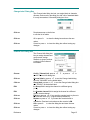
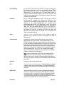
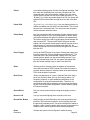
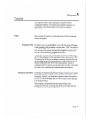
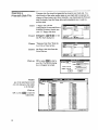
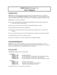
Dialog Boxes
Check boxes
Dialog boxes appear to let you input data to the program when
necessary.
Command Button
Field
Drop Down List Box
List Box
Radio Buttons
Check Boxes
Check boxes let you enable or disable a particular option. The
option is enabled when there is an "X" in the box.
Command Buttons
Command buttons let you specify an action. The OK Button and
Cancel Button are special case command buttons.
Drop Down List Box
The drop down list box provides a list box in a small amount of
space. You can identify it by the arrow on the right of what looks
like a standard text box. Click on the arrow to the right to drop
down the list box, with scroll bar if appropriate. Some drop down
list boxes let you make a text entry into the top box if there is no
suitable entry in the list.
Edit Fields
Edit Fields (sometimes called "fields" in this text) are text and
numeric entry boxes that let you enter a numeric value or a text
string, depending on the function. Where a default is appropriate,
the system will enter a default value into the field before opening
the dialog box.
List Box
List boxes present you with a choice of entries. You can select an
entry by scrolling to it if necessary, clicking on the entry, and then
clicking on OK, or by scrolling to the entry and double-clicking.
In many cases double-clicking on an object is the same as selecting the object and clicking on OK
or pressing
. In other cases, double clicking is programmed as a shortcut (sometimes
undocumented). In any Windows software, when you are first acclimatizing to the software you
should try double clicking on everything to see what happens.
Navigating in Windows
Page 8
Numeric Box
A field which requires a numeric entry.
Radio buttons
Radio buttons are used to present two or more mutually exclusive
choices. Clicking on one radio button will select that button and
deselect all other buttons in the group. A series of radio buttons is
sometimes called an "Option group."
Scroll Bars
Scroll bars let you scroll through a list to find the entry you wish to
select.
Text Box
A field in which you can enter text.
Using a Scroll Bar
Some windows and lists have scroll bars you can use to view text
that requires more than the available space.
Drag
the scroll button up or down the scroll bar (or left or
right in a horizontal scroll bar) to the position of choice.
The section of the document or list that moves into view
depends on the placement of the scroll box.
Click on
one of the scroll arrows to scroll one line
Click on
one of the scroll arrows and hold the mouse button down
to scroll continuously until the information you want comes
into view.
Scrolling with the
Keyboard
You can also scroll around the screen or a window by using
keyboard commands.
Press j , k , l , or i
to scroll in the direction of the arrow.
Press r
to scroll to the next "page" of information.
Press e
to scroll to the previous "page" of information.
Press h
to scroll to the beginning of a line.
Press u
to scroll to the end of the line.
Press v + h
to scroll to the beginning of the document.
Press v + u
to scroll to the end of the document.
Navigating in Windows
Page 9
Text Editing
Some windows, dialog boxes, and lists have text boxes that you
edit directly using Windows text editing techniques. The cursor will
change to an " Ι -beam" when it is over a text box.
Edit Using a Mouse
Position
the " Ι -beam" at the start of the text you wish to modify.
Drag
the " Ι -beam" to the end of the text you wish to modify (press the
left mouse button and hold it while moving the cursor).
Type
the new text. The old text will disappear and will be replaced with
the new text.
Replace an Entire Entry Using the Keyboard
Tab
to the text box. Each time you press t a new box or control will
be highlighted. When you get to the text box the entire entry will be
highlighted and the " Ι -beam" cursor will appear at the right end of
the entry.
Type
the new text. The old text will disappear and will be replaced with
the new text.
Replace Part of an Entry Using the Keyboard
Tab
to the text box. Each time you press t a new box or control will
be highlighted. When you get to the text box the entire entry will be
highlighted and the " Ι -beam" cursor will appear at the right end of
the entry.
Use
l and j to position the cursor to the left of the text you wish to
replace.
Use
y to delete the characters you wish to replace
Tab
to the next control or text box you wish to use, or press b if
you are finished with the dialog box.
Navigating in Windows
Page 10
Chapter 3
Installation
This chapter tells you how to install the Premiere Configuration
software on your personal computer.
The Basic
Necessities
To run the Premiere Configuration Program you will need the
following:
n
IBM PC-AT or 100% compatible MS/PC-DOS
computer that supports Windows 3.0 (or later) or Windows
95.
n
At least 2Mb of RAM.
n
A 720Kb or 1.44Mb disk drive.
Regardless of the disk type you have in your system, any diskettes, which are
to be used in the Premiere disk drive, must be formatted for 72OKb.
n
n
n
n
n
Installing the Files
Hard disks drive.
Microsoft Windows 3.0 or higher
MS-DOS 3.0 or higher.
A mouse is recommended but not essential.
A color monitor is recommended but not essential.
To install the Premiere Configuration software, copy the
PREMIERE.EXE file on the software diskette to the directory of
your choice.
If you are using Windows 3.0, you must also copy the
COMMDLG.DLL file to your Windows directory. You do not need
to copy COMMDLG.DLL to your Windows directory if you have
Windows version 3.1 or later.
Installation
Page 11
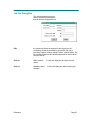
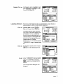
Starting the
Software
Start the Premiere Configuration software from Windows in the
most convenient manner for you. Please see your Windows User's
Guide if you have any questions about how to do this.
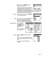
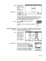
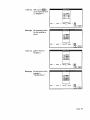
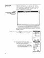
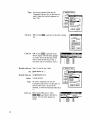
The Open dialog box
will appear on screen
the first time you start
the software. Whenever
you start the software
after this it will
remember the last
configuration file you
were working on and
automatically open that
file without showing the Open
dialog box.
Click on
CANCEL or press s to get to the Channel display and a blank
configuration file
For additional information on how to use the software, please see
the Tutorial chapter and the Reference chapter in this manual.
Installation
Page 12
Chapter
4
Reference
This chapter provides a detailed description of all of the menus,
screens, and dialog boxes. Page numbers are shown below.
Channel Display ............................................................................................................................ 14
Change Label Dialog Box ............................................................................................................. 15
Channel Info Dialog Box ............................................................................................................... 15
Clock Dialog Box........................................................................................................................... 16
Clock Display ................................................................................................................................ 17
Commands.................................................................................................................................... 18
Command List Dialog Box ............................................................................................................ 30
Config Menu .................................................................................................................................. 31
Dimmer Info Dialog Box................................................................................................................ 32
File Menu ....................................................................................................................................... 33
Files ............................................................................................................................................... 34
Job Info Dialog Box ....................................................................................................................... 35
Macro Dialog Box.......................................................................................................................... 36
Macro Display ............................................................................................................................... 37
Menu Bar ....................................................................................................................................... 38
Patch Display................................................................................................................................ 39
Preset Display............................................................................................................................... 40
Preset Info Dialog Box .................................................................................................................. 41
Print Dialog Box ............................................................................................................................ 42
Room Assignment Dialog Box...................................................................................................... 43
Room Info...................................................................................................................................... 43
Dialog Box ..................................................................................................................................... 43
Station List Dialog Box.................................................................................................................. 45
Station List Display ....................................................................................................................... 47
System Menu ................................................................................................................................ 48
Template Info Dialog Box ............................................................................................................. 49
Reference
Page 13
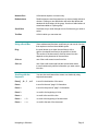
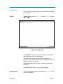
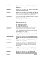
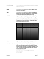
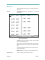
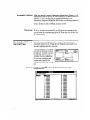
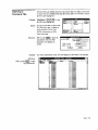
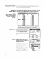
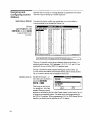
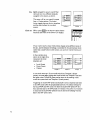
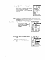
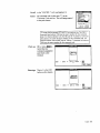
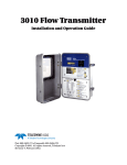
Channel Display
The Channel display lets you see your Channel to room
assignments
Choose
System Channel Display, press a+ S, C or
press v + C to see the Channel display.
Figure 3. Channel Menu
The Room column shows you where channels start for each
room. Entries appear in this column next to the first channel in
each room. The entry shows both the room number and its
designation. The default designation for rooms is "Room." You can
change this designation through the Room Info dialog box.
The Channel column shows you the channel number and
designation for each channel in the system. The default
designation for channels is "Channel." You can change this
designation through the Channel Info dialog box.
Double-click on
a channel or highlight the channel and press v + C (or a
+ C C) to see the Channel Info dialog box.
Double-click on
a room number or highlight the room number and press v +
R (or a + C R) to see the Room Info dialog box.
Double-right-click on
a channel, or highlight a channel and press v + A to see the
Room Assignment dialog box.
Reference
Page 14
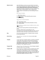
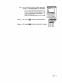
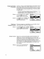
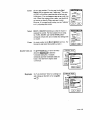
Change Label Dialog Box
The Change Label dialog box lets you assign labels to channels,
dimmers, and rooms by providing you with a list of standard labels.
It is only accessed as a secondary dialog box from: -
Click on
Drop down arrow on the list box
to see the list of labels.
Click on
OK or press b to close the dialog box and save the new
values.
Cancel or press s to close the dialog box without saving any
changes.
Click on
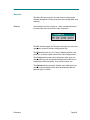
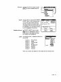
Channel Info Dialog Box
The Channel Info dialog box
lets you assign channel and
group names, assign
channels to groups, and set
a variety of other channel
information.
Choose
Click on
Click on
Edit
Edit
Click on
Click on
Click on
Click on
Reference
Config Channel Info, press a+ C C, or press v+ C to
see the Channel Info dialog box.
Channel label or press a+ C to see the Change Label dialog
box with "CHANNEL" as the default label.
Group label or press a+G to see the Change Label dialog box
with "GROUP" as the default label.
the Group field to assign the channel to a different group
(1-16).
the Console channel field to assign the channel to a different
control console channel.
Pile-on or press a+P if you want the console levels to pile on to
the Premiere levels (HTP - highest takes precedence).
Replace or press a+ E if you want the console levels to
override the Premiere levels whenever the console is ON.
OK or press b to close the dialog box and save the new
values.
Cancel or press s to close the dialog box without saving any
changes.
Page 15
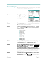
Clock Dialog Box
The Clock dialog box lets you set up time
and date repetition information for events
that are to be controlled by the
astronomical time clock.
Choose
Config Clock Info, press a+C L,
or press v+L to see the Clock dialog
box.
Enter
a 24 hour time into the Time field to set
the event time. Enter a minus sign (-) in
front of the time if it is to be a time relative to and before either
sunrise or sunset. Enter a plus sign (+) in front of the time if it is to
be a time relative to and after either sunrise or sunset.
Click on
Sunrise or press
Click on
Sunset or press a+N to make the time relative to sunset.
Click on
the arrow in the Type list, or press a+Y and then press a+ k
to see the list of repetitive day types. The following day types are
provided:
•
•
•
•
•
•
+
to make the time relative to sunrise.
Day of the week (Sunday, Monda y, Tuesday, Wednesday,
Thursday, Friday, or Saturday)
Weekday (Monday through Friday)
Weekend (Saturday and Sunday)
Mon-Sat (Monday through Saturday)
Everyday
Special Date (specific month and date).
Click on
an entry in the Type list, or highlight the entry using i or k and
press a+ i to select the day type. If the day type is 'SPECIAL"
the Date field will be activated.
Edit
the Date field if it is active. This sets the month and date on which
the event will be activated. It will only be activated once each year.
Double-click on
SPACE
SPACE
the Event field or highlight it and press
to see the Command list dialog box. This lets you set the event
type and command code for the event (see page 30).
Select
whether you want this clock event to act on a room or a station by
clicking on or selecting the appropriate Room or Station button.
Edit
the room/station number if you wish to make this event act on a
different room or station than is currently shown.
Click on
OK or press b to close the dialog box and save the new
values.
Click on
Cancel or press s to close the dialog box without saving any
changes.
Reference
Page 16
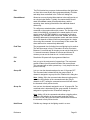
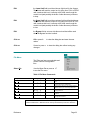
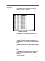
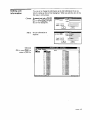
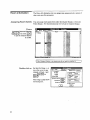
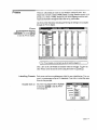
Clock Display
The Clock display lets you see all of your clock/event information
on one screen.
Choose
SystemClock, press a+ S L, or press v +5 to see the
Clock display.
Figure 4. Clock Display
The Day/Date column shows the day of week(s) or the specific
date on which the event is to be triggered.
The Time column shows the time of day the event is to be
triggered. Time is shown in 24-hour format, or labelled "Sunrise" or
"Sunset" and shown as an offset.
The Room column shows the room or station to on which the
event acts.
The Event column shows the type of event assigned.
Double-click on
Reference
an event or highlight a specific event and press v+L to see
the Clock dialog box.
Page 17
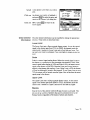
Commands
Most Premiere commands can be assigned to station buttons,
events, or to macros. These assignable commands are accessed
through the Command List dialog box. Commands are listed
alphabetically. Where command codes are either optional or
required, they are listed below the main command entry. Valid
codes are in the range of 1 to 256.
Many of the functions mention operating on the second fader. The
Premiere processor is structured similarly to many control
consoles. 'The presets are played back on one of two faders. This
means that each room can have two presets active at the same
time. Presets assigned to the same fader replace one another as
each new preset is recalled. Presets on different faders do not
replace each other, but contribute to overall channel levels on a
"highest takes precedence" basis. "Off' works on the A fader only.
If presets are active on both faders only A goes off.
Many of the functions are designed to be used on the 2300
Command stations or 2200 Display stations with LCD displays
and/or numeric keypads. Although they can be assigned to other
types of stations, you should avoid this since using them on other
types of stations will make these functions either difficult to use, or
very confusing to the user.
0-9
(Suggested Usage: 2300 Stations Only). Numeric entry buttons used
on the 2300 Command Station for selecting rooms, stations,
presets, channels, levels, etc.
1000 Preset
(Suggested Usage: 2300 Stations Only). Allows the preset currently
loaded on the "B" fader to be displayed on 2300 stations. This
command must be entered directly at the 2300 keypad by pressing
"1", "0", "0", "0", then "PRESET".
And
(Suggested Usage: 2300 Stations Only). Used for grouping channels
on the 2300 Command Station.
Bypass
Takes all channels to their assigned bypass level (Panic). Normal
operation is restored with the Reset key. All channels are assigned
a bypass level during system configuration.
Channel
Selects a channel within the room currently addressed by the
control station. The command code represents the channel
number.
Channel 2300
(S uggested Usage: 2300 Stations Only)
Selects a channel within the room currently addressed by a 2300
control station. The channel number is taken from the 0-9 keypad.
Channel 2200
(Suggested Usage: 2200 Stations Only). Lets you display channel
Reference
information in a format compatible with the 2200 LCD Display
Station. The command code is the channel number to be
displayed, and is usually set between 1 and 6. Additional channel
data is accessed by using “Page+” and “Page-.”.
Page 18
Channel Ramp
Lets you hold a button with the intensity of a channel moving from
the beginning intensity to FULL, then ramping back to ZERO.
When you release the button the channel will remain at the
released level. You can then use the "Channel Ramp" button to
toggle the channel instantly between OFF and the new level. The
command code represents the local channel number in the room
currently being addressed.
Cleanup
One of 128 presets available per room. The default is preset #
126, but can be changed in the `Room Info' dialog box. This
command lets you assign lighting channels for use during room
cleanup. In its default configuration the Cleanup preset
automatically fades to the OFF preset after 1 hour. This may be
easily modified in the `Preset Display' dialog box by adjusting the
`Hold' time. Since the default fade time for the OFF preset is 5
minutes, users will have 5 minutes of warning at the end of the
hour before the lights go out, during which time they can easily
reactivate the cleanup preset for another hour (or whatever the
`Hold' time has been set to).
Clear
(Suggested Usage: 2300/2200 Stations Only). Used to clear an
incorrect entry or cancel an incorrect command on the 2300 or
2200 stations.
Console Input
Activates the Console Input facility within the room currently
addressed by the control station. Local channels can be set to
"Pile-On" (highest takes precedence between the local levels and
the first 128 console dimmer signals) or "Replace" (the level of one
of the first 128 dimmer channels of the console signal is directly
transferred to the channel level in Premiere). This assignment is
made in the "Channel Info" window of the Configuration Software,
and must be between 1 and 128. This command has a toggle
action. The first time it is called, the "Console Input" is activated.
Calling it a second time deactivates it.
Note: If the command code is set to 255, the command will be
called in the room without affecting the current Console Input
status of other rooms. All other command codes will be ignored,
and only one room will be able to have CONSOLE INPUT enabled
at any time.
Date Set
Lets you set the current system date.
Dec
(Suggested Usage: 2200 Stations Only). Decrements the ones digit in
a number entry field on a 2200 station. The digit underlined by a
flashing cursor will scroll from 9-0 repetitively while the button is
pressed.
Delay Time
When accessing presets, the amount of elapsed time between
selection of a preset and the start of the actual fade. The delay
time range is from 0.1 seconds to 8 hours 59 minutes. Between
0.1 seconds and 30 minutes you can set the delay time in 0.1
second increments. Between 30 minutes and 8 hours 59 minutes
you can set the delay time in 1 minute increments.
Reference
Page 19
Enter 2300
(Suggested Usage: 2300 Stations Only). Lets you record the current
lighting levels in the room from a 2300 station. This records the
actual current light levels, regardless of the source of control for
each channel.
Event Clear
(Suggested Usage: 2300 Stations Only). Clears the selected clock
event on the 2300 Command station.
Event Date
(Suggested Usage: 2300 Stations Only) . Lets you work with the
astronomical time clock via a 2300 station, and program a date for
events which will be controlled by the clock. Dates are in MM/DD
format, or are a number representing the repetitive date type.
Event Lockout
Provides the ability to enable or disable clock events from a station
pushbutton directly, or via a Macro.
The command codes for direct operation are:
1 to 32 - Enable/Disable events in a specified room.
The command codes for macro use (where the room address is
identified within the macro) are:
254 - Disable events in this room
255 - Enable events in this room
256 - Toggle clock events in this room
Event Lockout
Maintained
As "Events Lockout" but operation from a key switch or other
maintained contact. Command code options are as follows:
1 to 32 - Enable/Disable events in specified room (the command
code represents the room number)
255 - Enable/Disable events in all rooms
256 - Enable/Disable events in this room (i.e. the room currently
being addressed by the local control station to which the
maintained switch is connected)
Event Lockout 2300
(Suggested Usage: 2300 Stations Only). Provides the ability to enable
or disable events within selected rooms using the 2300 Command
station.
Event Page 2
(Suggested Usage: 2300 Stations Only). Displays the second page of
clock information on a 2300 station.
Event Preset
(Suggested Usage: 2300 Stations Only). Digits keyed into the 2300
Command station in the range of 1-128 are entered as "Event
Preset" after event time, event date; and a room number have
been specified.
Event Template
(Suggested Usage: 2300 Stations Only). Lets you record a template
event. The template required is selected on the 2300's numeric
keypad after an event time, event date, and a station has been
specified.
Event Time
(Suggested Usage: l300 Stations Only). Lets you work with the
astronomical time clock via a 2300 station, and program events
which will be controlled by the clock. Times are in HH/MM format.
Page 20
Reference
Exit
The Exit function lets you press a button and have the lights fade
out from their current levels after a programmed delay. Exit fade
and delay times are defined in the `Room Info' dialog box.
Extend Manual
Allows two or more physical slider stations to be configured to act
as a single logical station. Typically, the master station should
retain the standard master pot and pushbuttons, and the
remaining slave station(s) should have the additional channel
sliders only.
To configure an extended station, substitute the MANUAL
command on the master station with a macro. The first step of the
macro is the MANUAL command for the master station; the next
step(s) would be EXTEND MANUAL command(s) for the slave
station(s). The command code is not used. Instead, the macros
should be addressed to the appropriate master and slave stations.
Up to 128 channels of slider control may be assigned to a single
room using this command. It is not necessary for the master and
slave stations to be consecutively addressed.
Fade Time
The programmed time for fading from one lighting level to another.
The fade time range is from 0.1 seconds to 8 hours 59 minutes.
Between 0.1 seconds and 30 minutes you can set the fade time in
0.1 second increments. Between 30 minutes and 8 hours 59
minutes you can set the fade time in 1 minute increments.
Full
Recalls the ON preset with its programmed fade time.
Go
Lets you go to the next preset of a preset loop. The next preset
number is taken from the preset link field of the current preset.
This command will not start a preset loop - it only steps to the next
preset in the loop.
Group Off
Lets you turn the channels assigned to one of 16 groups OFF.
The command code is determined by the group number. A
channel is assigned to a group from the 'Channel Info' dialog box.
Note: Adding 128 to the command code allows a toggling action,
so that the first initiation of the command sends the group's
channels to OFF; calling the command a second time will restore
the channels to their previous levels.
Group On
Lets you turn the channels assigned to one of 16 groups ON. The
command code is determined by the group number. A channel is
assigned to a group from the 'Channel Info' dialog box.
Note: Adding 128 to the command code allows a toggling action,
so that the first initiation of the command sends the group's
channels to ON; calling the command a second time will restore
the channels to their previous levels.
Hold Room
Reference
Prohibits any changes to the lighting control in a room.
Page 21
Hold Time
The programmed time that a preset will wait after it is completed
and before moving to the next preset. Hold times are most
commonly used to create a series of automatic changes, or loops
in lighting presets. The hold time range is from 0.1 seconds to 8
hours 59 minutes. Between 0.1 seconds and 30 minutes you can
set the hold time in 0.1 second increments. Between 30 minutes
and 8 hours 59 minutes you can s et the hold time in 1 minute
increments.
If
Provides the ability to test the current state of various system
conditions, and modify macro execution accordingly:
Branching on switch inputs:
The macro address is the station whose input is to be tested. The
command argument is the switch (button) number to test, resulting
in a legal range of 1-18 depending on the station type. If the tested
input is pressed (closed) the next sequential macro is executed;
otherwise, the macro specified by the "Next Macro" field is
executed.
Branching on station template:
The macro address is the station whose template is to be tested.
The command argument is the template to test plus 32, resulting
in a legal range of 33-48 depending on the number of templates
assigned to the station. If the tested template is the active
template the next sequential macro is executed; otherwise, the
macro specified by the "Next Macro" field is executed.
Branching on station LED’s:
The macro address is the station whose LED state is to be tested.
The command argument is the LED number to test plus 48,
resulting in a legal range of 49-54 depending on the number of
LED’s on the station. If tested LED is illuminated, the next
sequential macro is executed, otherwise the macro specified by
the "Next Macro" field is executed.
Branching on presets:
The macro address is the room whose preset is to be tested. The
command argument is the preset number to test. The current
preset for the "B" fader may be tested by adding 128 to the preset
number. If the tested preset is the current preset the next
sequential macro is executed, otherwise the macro specified by
the "Next Macro" field is executed.
Inc
(Suggested Usage: 2100 Stations Only). Increments the ones digit in a
number entry field on a 2200 station. The digit underlined by a
hashing cursor will scroll from 0-9 repetitively while the button is
pressed.
Inhibit
Turns dimmers assigned to the function OFF. Use Reset to restore
lights. The command code represents the local channel number.
Reference
Page 22
Init Macro
Defines a macro sequence which will be executed automatically
upon power up, completion of a disk load, or when the ‘RESET A’
button is pressed. Premiere checks macros 1,2 and 3 whenever
any of these events occur. Any "INIT MACRO" commands found
at those locations will be executed. It is important to note that the
INIT command will not be recognized in any macro location other
than 1,2 or 3. The command code selects the events sequence
which will execute the Macro. Note that only a single INTT macro
will be executed per event.
Command code:
1 - Undefined, do not use
2 - Execute macro at power on
3 - Execute macro after a disk is loaded
4 - Execute macro at power up or when disk is loaded
5 - Execute macro when ‘RESET A’ is pressed
6 - Execute macro at power on or when ‘RESET A’ is pressed
7 - Execute macro after a disk is loaded or when `RESET A' is
pressed
8 - Execute macro after at power up, after a disk is loaded, or
when ‘RESET A’ is pressed
9-256 - Undefined, do not use.
Label
(Suggested Usage:2200 Stations Only) Provides the ability to display
user-defined text on a 2200 display screen. This command will
typically be the first step of a macro. When the command is
selected, a scrolling dialogue box pops up, and any of 256
possible user-defined labels can either be selected or typed
directly into the box. The associated LED will be updated in
accordance with the second step of the macro.
Note: If the LABEL is placed directly on a 2200 station button, or if
there is not a second macro step, the LED will never illuminate.
Latitude
(Suggested Usage:2300 Stations Only). Lets you enter the latitude for
sunrise/sunset calculations. The current latitude setting is
displayed if no numbers have been entered.
Level
(Suggested Usage:2300 Stations Only). Terminates a level entry.
Link Interlock
This command is required for room combinations. When activated
manually, the button assigned as "Link Interlock" is pressed and
held while "Link Room" buttons are selected to identify the rooms
to be combined. On release, the rooms combine. When combining
manually, no command code is required. When combining
automatically via macros, however, the following command codes
are used:
129 - Begin Link Interlock on key press; ignored on key release
130 - End Link Interlock on key press; ignored on key release
131 - Begin Link Interlock on key release; ignored on key press
132 - End Link Interlock on key release; ignored on key press
133 - Begin Link Interlock on key press OR release
134 - End Link Interlock on key press OR release
Reference
Page 23
Other - Begin Link Interlock on key press, end on key release
(Used for manual combining at stations)
Link Room
Used with Link Interlock to specify the room to link. The command
code represents the room number.
Lockout
(Suggested Usage: 2300 Stations Only). Locks out the local station
with a toggle action in one of three ways depending on the
command code used as follows:
1. Total Lockout
2. All other station in room locked
3. Record Lockout
The lockout type is entered on the 0-9 keypad following selection
of the station number. Set the "Lockout" command code on the
station to 1 during configuration.
Lower
When a preset is selected, fades all channels in the preset
towards OFF while the button is held. When a channel is selected,
fades the level of that channel towards OFF.
Macro 1 - 256
Lets you select a macro between 1 and 256 (inclusive). The
command code is the starting macro number.
Macro 257- 512
Lets you select a macro between 257 and 512 (inclusive). The
command code is the starting macro number minus 256.
Macro 513 - 768
Lets you select a macro between 513 and 768 (inclusive). The
command code is the starting macro number minus 512.
Macro 769 - 800
Lets you select a macro between 769 and 800 (inclusive). The
command code is the starting macro number minus 768.
Manual
Lets you take manual control of channels on a station with sliders.
In the `Room Info' dialog box, the following options may be
selected:
•
Whether pressing the `Manual' button a second time will
take the associated station out of manual control, and if so,
whether the room to which that slider station is assigned will revert
to the last selected preset, or go to OFF.
•
Whether channels which are assigned to a room, but not
controlled from a slider station in that room will remain at their
current levels, or black out when that station takes manual control
of the room's channels.
Manual LED
Reference
Used in conjunction with the "READ TlMES" command to provide
user adjustment of a room's `Manual Fade' time using a pot on
any Premiere slider (23xx or 28xx series station). See the "READ
TIMES" command for further description. The "MANUAL LED"
command simply illuminates the associated LED when the station
is in manual mode, and has no other effect on system operation.
Page 24
Menu 2200
(Suggested Usage: 2200 Stations Only). Lets you display a number of
standard text lines on a 2200 LCD Display Station. The command
code defines what will be displayed.
1.
"PREMIERE"
2.
Job Name
3.
Job Location
4.
Today's Date
5.
Current Time
6.
Room Name
7.
Entry field. ('The `<' button must be assigned the `Number
Shift' function if you use this display.)
Note: Text lines 1 through 6 are normally shown on the first
template of a 2200 station as the `Project Information' screen.
N/A
Not assigned. This is tbe standard command applied to a station
button that is to have no function.
Non-Dim
A push-button which lets you toggle a channel ON or OFF. The
command code represents the channel number. To program the
channel into fader B, use channel number plus 128 as the
command code.
Non-Dim Maintained
A push-button which turns a channel ON when pressed and OFF
when released. The command code represents the channel
number. To program the channel into fader B, use channel
number plus 128 as the command code.
Number Shift
(Suggested Usage: 2200 Stations Only). Shifts the number in the Entry
field of a 2200 station (see Menu 2200 above) over one digit,
leaving a ZERO in the right most digit.
Off
One of the 128 presets per room. The default is preset #127, but
can be changed in the `Room Info' dialog box. Usually this turns
lights OFF, although in certain cases, some lights may be left at a
low level for safety or security. Using this function sets the lights to
the levels in the OFF preset immediately, regardless of the fade
time shown.
On
One of the 128 presets per room. The default is preset #128, but
can be changed in the `Room Info' dialog box. Brings the lights to
a predetermined level. Using this function sets the lights to the
levels in the ON preset immediately, regardless of the fade time
shown.
Out
Calls the OFF preset, but with its programmed fade time.
Page
(Suggested Usage: 2200 Stations Only). Scrolls through station
templates. Pressing "Page" loads the next template in numerical
sequence onto the local control station.
Page+
(Suggested Usage: 2200 Stations Only). Loads the next set of
channels or presets into the display of a 2200 control station.
Page-
(Suggested Usage: 2200 Stations Only). Loads the previous set of
channels or presets into the display of a 2200 control station.
Reference
Page 25
Preset
A pre-defined lighting setup. Presets store lighting intensities, fade
time, hold time, and delay time in memory for later recall. The
command code is the preset number. Adding 128 to the preset
number puts the preset onto the second fade processor (i.e., the
`B' fader). If you input any number larger than 256, the system will
subtract 256 from the number enough times to make it less than
256.
Preset 2300
(Suggested Usage: 2300 Stations Only). Lets you display presets in a
manner compatible with the 2300 Command Station. This function
does not use a command code. The user must enter the preset
number and then select this button.
Preset Ramp
Lets you hold a button with the intensity of lights moving from the
beginning intensity to FULL, then ramping back to ZERO. When
you release the button the lights will remain at the released level.
This button can then be used to toggle lighting levels between the
new level and OFF. The command code is the preset number.
Adding 128 to the preset number puts the preset onto the second
fade processor. If you input any number larger than 256, the
system will subtract 256 from the number enough times to make it
less than 256.
Preset Toggle
Acts as an ON/OFF button for a preset. Pressing the button once
turns the preset ON. Pressing it again turns the preset OFF. The
command code is the preset number. Adding 128 to the preset
number puts the preset onto the second fade processor. If you
input any number larger than 256, the system will subtract 256
from the number enough times to make it less than 256.
Raise
When a preset is selected, fades all channels in the selected
room with levels above ZERO towards FULL while the button is
pressed. When a channel is selected, fades the channel towards
FULL while the button is pressed.
Read Times
Allows user adjustment of a room's `Manual Fade' time using a
pot on any Premiere slider (23xx or 28xx series) station. It is
necessary, however, to make additional modifications to the
configuration file using a hexadecimal editor. Therefore, it is
recommended that this programming only be done by the factory
as part of an initial system configuration. Contact Strand Lighting
for further information
Record Blind
Lets you record a preset without seeing the changes you have
made.
Record Look
Lets you record the lighting levels currently in the room.
Record One -Button
Used primarily on the 2208 station, this command performs two
functions. The first action records the current lighting levels into
the previously selected preset. The second changes the station to
template 1 (this reverts the station back to preset recall mode from
channel mode in which channel levels have been adjusted)
Reset
Reference
Restarts the system from the Bypass or Inhibit functions.
Page 26
Reset Watchdog
Allows the processor's watchdog timer to be explicitly reset during
long macro sequences.
Room
(Suggested Usage: 2300 Stations Only). Lets you address different
rooms from a 2300 station.
Shift
(Suggested Usage: 2300 Stations Only). Lets you access another
template in the 2300 station without changing the room number.
The command code represents the template number.
Shift 2200
(Suggested Usage: 2200 Stations Only). Selects one of the 16
available templates on a 2200 display station, and displays the
correct information for that template on the LCD screen. By
default, a standard 2200 station has 5 templates already written.
These are generally not modified, but they may be deleted, edited
or appended to in custom applications. The command codes to
select templates are as shown below:
Template #
1
2
3
4
5
6
7
8
9
10
11
12
13
14
15
16
Command Code
1
2
19
36
53
70
87
104
121
138
155
172
189
206
223
240
Default Screen
Project Info
Preset
Menu Select
Channel
Record
-
Station
(Suggested Usage: 2300 Stations Only). Lets you enter a station
number between 1 and 64 (inclusive) on the 2300 station.
Station Lockout Event
(Suggested Usage: 2300 Stations Only). Used for locking out control
stations as an automatic event entered from the 2300 Command
station. The lockout option required is determined by entering a
number 1 through 5 keyed into the Command station after "Event
Time", "Event Date" and Station Number have been specified.
Lockout types are as follows:
1 - Total Surface Lockout
2 - All other stations in room locked (Remote Lockout)
3 - Record Lockout
5 - Unlock Station
Reference
Page 27
Station Lockout
Used within Macros to lockout one control station from another.
The command code determines whether a toggle action (i.e. such
as from a station pushbutton), or a direct action (such as from a
macro) is being used to implement the lockout. Selecting any
toggle action command a second time will reverse the action. The
station number is defined within the macro, followed by the
"Station Lockout" command with one of the following command
codes:
Direct Action; For Macros
1 - Total Surface Lockout
2 - All other stations in room locked (Remainder Lockout)
3 - Record Lockout
5 - Unlock Station(s)
Toggle Action; For Station Pushbuttons
129 - Total Surface Lockout
130 - All other stations in room locked (Remainder Lockout)
131 - Record Lockout
Note: The following command codes may be added to the above codes to
modify their action.
32 - LED Action Reversed (LED is illuminated when station is
active)
64 - Room Lockout (Locks out all stations in a room
simultaneously. This command should ONLY be used in a macro;
otherwise the station issuing the command will lock itself out!)
Stop
Lets you stop a fade in progress. Pressing the button a second
time will restart the fade.
Sunrise Enter
(Suggested Usage: 2300 Stations Only). Lets you enter today's
sunrise time.
Template
Lets you have up to 16 different "pages" of functions on the same
control station. Each template can be accessed by calling the
command from a station button or macro, or it can be changed
automatically by the astronomical time clock. The command code
represents the template number. The LED illuminates whenever
the station is in any template other than ‘1’.
Template 2300
(Suggested Usage: 2300 Stations Only). Lets you change a template
on another station from a 2300 station.
Template LED
Lets you have up to 16 different "pages" of functions on the same
control station. Each template can be accessed by calling the
command from a station button or macro, or it can be changed
automatically by the astronomical time clock. The command code
represents the template number. The LED illuminates whenever
the specified template on the station is active.
Reference
Page 28
Thru
(Suggested Usage: 2300 Stations Only). Lets you group channel
numbers together to facilitate programming on the 2300 station.
Time Set
(Suggested Usage: 2300 Stations Only). Lets you set the current
system time.
Reference
Page 29
Command List Dialog Box
The Command List dialog box lets you assign commands
to station buttons or clock events.
You can get to this dialog box
from a station diagram or
from the Clock dialog box.
Please see under Clock
Dialog Box and Template Info
Dialog Boxes elsewhere in
this chapter.
Click on
an entry in the Command list or highlight the entry using i or k
and select the command. Pressing the first letter of the command
you want will send you to the next listing starting with that letter.
You can continue to press the letter to see additional entries
starting with the same letter.
Edit
the Command code field if you wish to change the command code.
Valid commands and command codes are listed in the Command
List section of this chapter.
Click on
OK or press b to close the dialog box and save the new
values.
Click on
Cancel or press s to close the dialog box without saving any
changes.
Double-click on
an entry in the Command list or highlight the entry using I or k
and press b to select the command and close the dialog box.
This method does not let you select or modify the command code.
Reference
Page 30
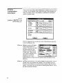
Config Menu
The Config menu lets you access
all of the configuration information
for your system.
Select
Config from the Menu Bar or
press a+ C to get to the file
menu.
Table 1. Configuration Menu Commands
Mouse Command
Menu Command
Shortcut
Description
ConfigRoom Assignment
a+ C A
v+A
Lets you assign rooms to channel sequences
ConfigChannel Info
a+ C C
v +C
Lets you assign names to channels and groups
and record other channel information.
ConfigRoom Info
a+ C R
v+R
Lets you name rooms and record other room
specific information.
ConfigPreset Info
a+ C P
v+P
Lets you assign names to presets and record other
preset specific information.
ConfigStation Info
a+ C S
v+S
Lets you design the station functions.
ConfigTemplate Info
a+ C T
v+T
Lets you configure templates for stations.
ConfigDimmer Info
a+ C D
v+D
Lets you assign names to dimmers and set up
dimmer to channel patching information.
ConfigClock Info
a+ C L
v+L
Lets you configure and set up the clock and event
information.
ConfigM acro Info
a+ C M
v+M
Lets you set up information for a single macro
command.
If you select an item in this menu that is not currently highlighted
on the screen, you will get the previous selection for this item. For
instance, if you are in the Channel display and choose "Clock Info"
you will get the last selected clock item. To actually select an item,
you should first get to the correct screen using the System menu
item, select the appropriate item from the screen, and then use the
Config menu to modify the selected item.
Reference
Page 31
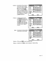
Dimmer Info Dialog Box
The Dimmer Info dialog box lets you name a dimmer, setup patch
information for it, and set dimmer level limits.
Choose
Config Dimmer Info, press
a+ C D or press
v+D to see the Dimmer
Info dialog box.
Click on
Dimmer label or press a+
to see the Change Label dialog
box with "DIMMER" as the default label
Click on
the arrow in the Dimmer curve field or press a+ C and then
a+
to see the list of dimmer curves. The following dimmer
curves are provided:
n
n
n
n
n
n
n
n
n
Click on
Dimmer Default
Square law
Linear Light
Linear Voltage
S Law
Fluorescent
Non-dim 5%
Non-dim 50%
Non-dim 95%
an entry in the Dimmer curve field or select the entry using i or
k and then press a+i to select a dimmer curve.
Click on
an entry in the Room/Channel list or press a+R to get to the
to
list, select the entry using i or k and press
SPACE
add the channel to the dimmer.
You can have any number of channels controlling the same
dimmer, and you can have any number of dimmers controlled by
the same channel. For dimmers controlled by multiple channels,
when more than one channel is ON, the highest reading will
appear in the room.
Click on
a highlighted entry in the Room/Channel list or select the entry
using i or k, and press
to delete the channel
SPACE
from the dimmer.
Reference
Page 32
Edit
the Lower limit field to set the minimum light level for the dimmer.
The dimmer will track the control as it is going from FULL to ZERO
until it reaches this level. It will stay at this level even though the
control level (and possibly the levels of other dimmers) continues
to drop.
Edit
the Upper limit field to set the maximum light level for the dimmer.
The dimmer will track the control as it is going from ZERO to FULL
until it reaches this level. It will stay at this level even though the
control level (and possibly the levels of other dimmers) continues
to rise.
Edit
the Bypass field to set over-ride dimmer level that will be used
when the Bypass function is called.
Click on
OK or press b to close the dialog box and save the new
values.
Click on
Cancel or press s to close the dialog box without saving any
changes.
File Menu
The File menu lets you manipulate and
control Premiere Configuration
files.
from the Menu Bar or press a+F
Select File
to see the File menu.
Table 2. File Menu Commands
Mouse Command
Menu Command
Shortcut
Description
FileNew
a+ F N
Lets you open a new Premiere Configuration
File.
File Open
a+ F O
File Save
a+ F S
File Print
a+ F P
Lets you open an existing Premiere
Configuration File for modification.
Lets you Save the file you are currently working
on with its current name. You can sav e it with a
different name if you wish to keep the old file.
Lets you print information from the Premiere
Configuration file.
File Exit
a+ F X
Lets you exit the Premiere Configuration
software.
File About Premiere
a+ F B
Lets you get information about the Premiere
Configuration Software.
Diskettes must be formatted for 720Kb before you can use them for saving files.
Disks formatted for 1.4Mb will not be read by the Premiere processor disk drive.
Reference
Page 33
Files
Before starting the program, you should be aware of the file
conventions used by this program.
Premiere Files
By default, when you use FILE | S AVE to save a file the system
will suggest a name consisting of the job number, a hyphen, and a
".PRE" file extension (e.g., 12345-.PRE). Files with this extension
are referred to as "Premiere files" throughout this manual. Note
that the FILE | S AVE command is the same as a normal Windows
FILE | SAVE AS command.
You can save a Premiere file with any name you wish, but finding
it with the File Open dialog box will be much easier if you at least
use the ".PRE" file extension for all files you are editing or
archiving. Saving the file with the job number can be a very
convenient way to archive and keep track of multiple configuration
files. If you wish to keep multiple versions of configuration files for
each job, you can easily enter a number or letter after the hyphen
(up to a maximum of 8 characters before the extension).
Premiere Disk Files
The file that is transferred to the Premiere Program Module must
be named "FILE1.E3". This file is referred to as the "Premiere disk
file" throughout this manual. Generally, you should edit a separate
Premiere file and save it as FILE1.E3 only to the floppy disk you
will be using to transfer that data to the Program Module.
When bringing a configuration from the Program Module to the
Configuration Software, you should open the file on the floppy
disk and immediately save it as a Premiere file with a unique
name.
Automatic File Open
When you start the Premiere Configuration software from
Windows, it will automatically open the last file you were working
on. If it has no record of a last file (i.e., this is the first time you
opened the software, or you inadvertently erased the
PREMIERE.INI file from your Windows directory) you will get the
File Open dialog box, and must then choose a file (if there are any
on disk) or click on CANCEL to start a new file.
File Errors
If you try to open a non-existent file you will get an error message
telling you that there was a problem opening the file. When you
click on OK a new file will be started.
Reference
Page 34
Job Info Dialog Box
The Job Info dialog box lets you
specify the basic job information
that will follow a configuration file.
Edit
the various text boxes as required for the project you are
configuring. Boxes are provided for job number, job name,
processor number, location, latitude, creator, and last editor. The
job number will become the default base name for the file when
you save the file.
Click on
OK or press b to close the dialog box and save the new
values.
Click on
Cancel or press
changes.
Reference
to close the dialog box without saving any
Page 35
Macro Dialog Box
The Macro dialog box lets you set up
individual macro commands.
Choose
Config | Macro Info, press a+C M
or press v+M to see the Macro dialog
box.
Individual macro commands can be
chained together using the Next Macro
box to create a series of commands that will be executed in
sequence.
Premiere lets you have up to 800 macro steps split between as
many or as few macros as you wish.
When calling a macro from a station or room, the macro number is
(and thus the command code) is the number of the step from
which you will start the macro. If the macro is a loop you can start
the series from any step in the loop. If the macro is a series of
commands with an end point you can start the series at any step
and it will execute the steps from the entry point until it reaches the
last step in the macro.
Enter
the next step number in the Next Macro field if you wish another
step to be sequenced with the currently selected step. An entry of
ZERO will tell the system that this is the last step in the macro.
Select
Room or Station depending on what the macro is supposed to
control.
Enter
the room number in the box next to the Room and Station
selections.
Double-click on
the Command entry or tab to the entry and
SPACE
SPACE
press
to open the
Command dialog box and select a command for this macro.
Available commands and their command codes are listed earlier in
this chapter under Commands.
Click on
the Remove entry if you wish to remove all information from this
macro. The macro number will still appear in the Macro display.
Click on
OK or press b to close the dialog box and save the new
values if the Remove box is not checked, or remove all
information from this macro if the Remove box is checked.
Click on
Cancel or press s to close the dialog box without saving any
changes.
Page 36
Reference
Macro Display
The Macro display lets you see all of your macro information on
one screen.
Choose
System | Macro, press a+ S M or press v+6 to see the
Macro display.
Figure 5. Macro Display
The Macro column shows the macro number. This is the number
you will use when calling a macro.
The Link column shows the next macro number to be executed
after this macro. If there is no next macro, this column will show
"
End."
The Loc (Location) column shows the room or station to which
each command applies.
The Command column shows the command assigned to each
macro.
Double-click on
Reference
a macro command to see the Macro dialog box.
Page 37
Menu Bar
The Menu Bar lets you get to the other menus in the program.
Detailed descriptions of various functions are included under each
submenu.
Click on
the required menu item or press a and the underlined letter of
the menu item at the same time to open a submenu.
The File selection opens the File menu which lets you start, store,
open, save, and print Premiere Configuration files.
The Edit selection lets you Cut, Copy or Paste a selection, and
allows you to clear the patch when in the Patch Display screen.
The Config selection opens the Config menu which gives you
direct access the main configuration dialog boxes which let you
manipulate individual dimmers, clock events, macros, etc..
The System selection opens the System menu which gives you
access to system displays which show all information about a
particular type of function.
Reference
Page 38
Patch Display
The Patch display lets you see all of your channel/dimmer
assignment information on one screen.
Choose
System | Patch, press a+ S P, or press v+4 to see the
Patch display.
Figure 6. Patch Display
The Dimmer column shows the dimmer number and name.
Dimmer numbers are consecutive and do not change. You can
change the dimmer name from the Dimmer Info dialog box.
The Lower column shows the Lower Limit for the dimmer. The
dimmer level will never go below this level, regardless of the
channel settings.
The Upper column shows the Upper Limit for the dimmer. The
dimmer level will not go above this level, regardless of the channel
settings.
The Scale column shows the scaling factor applied to the dimmer.
This represents the level the dimmer will be at when controllers tell
it that it is at FULL. Lower Limit and Upper Limit are applied after
the scale factor.
The Curve column shows the current curve of the dimmer control
signal.
The Channels column shows the channels that will control the
dimmer. The display format for this information is [room #][channel #]
Double-click
Reference
on a dimmer or highlight the dimmer and press b to see the
Dimmer Info dialog box.
Page 39
Preset Display
The Preset display lets you see your preset information.
Choose
System | Preset Display, press a+ S P, or press v+2
to see the Preset Display
Figure 7. Preset Display
The first line of each room shows the room number and name, and
then lists the preset numbers across the top of the screen. To get
to additional presets you will have to scroll the display.
Channel numbers and names for each room, along with their
levels in each preset, are listed below the room information.
Double-click
on a room number or highlight the room number and press
v+R to see the Room Info dialog box.
Double-click
on a channel or highlight the channel and press v+C to see
the Channel Info dialog box.
Double-click
on a preset or any level in the preset, or highlight the preset or a
level and press v+P to see the Preset Info dialog box.
Click
Reference
on a level and type a new two-digit level to set or modify levels.
Page 40
Preset Info Dialog Box
The Preset Info dialog box lets you name a preset, assign the next
preset, and assign preset Delay, Hold, and Fade times.
Choose
Config | Preset Info, press a+C P, or press v+P, or
double-click on a preset number in the Preset display to see the
preset info dialog box.
Click on
Preset label or press a+P to see the Change Label dialog box
with "PRESET" as the default label.
Edit
the Next Preset field to change the next preset that will be
activated if there is a Hold time specified. The default value is the
current preset plus one.
Edit
the Delay time field to specify the time between when a preset
button is pressed and when the fade into the preset starts. Delay
time is entered in HH:MM:SS.T format. The default value is ZERO.
Edit
the Fade time field to specify the time it takes for lights to fade
from their previous levels to the levels recorded in the new preset.
Fade time is entered in HH: MM: SS.T format. The default value is
5 seconds.
Edit
the Hold time field to specify the time between when a preset fade
is complete and when the next preset is automatically activated.
Hold time is entered in HH: MM: SS.T format. The default value is
ZERO.
Click on
OK or press b to close the dialog box and save the new
values.
Click on
Cancel or press s to close the dialog box without saving any
changes.
Page 41
Reference
Print Dialog Box
The Print dialog box
lets you print all or part
of the information
about the current
Configuration file.
Choose
File l Print, or press
a+ F P to see the
Print dialog box.
Click on
Setup to access the Windows Printer Setup dialog box if required.
Click on
the k next to the list box to select your printer if required. This list
will only show your currently active printers. You will need to go to
the Windows Control Panel if you wish to activate a printer that is
currently inactive.
Click on
the check box for any item you do not wish to print. The default is
to print all numbers of all items.
Click on
the From selection button, press a+F or a+A or use
to get to the appropriate set of radio buttons, and press l to tell
the system that you wish to enter a range of numbers.
Enter
the starting and ending numbers for the item you wish to print.
You do not need to enter category ranges if you wish to print all of
the items in the category. The All radio button is selected by
default. If you have input a range of items and you wish to change
back to All you can press a+F or a+A or use
to
get to the appropriate set of radio buttons, and press
the All button.
j to select
Click on
OK or press b to print the selected items.
Click on
Cancel or press s to close the dialog box without printing.
Reference
Page 42
Room Assignment Dialog Box
The Room Assignment dialog
box lets you assign a room
change to the selected channel
in the Channel display.
Choose
Config| Room Assignment
press a+ C A, or
press v+A to see the Room Assignment dialog box.
Edit
the Change to Room # field to select a new room number for the
currently selected channel.
Click on
values.
OK or press b to close the dialog box and save the new
Click on
Cancel or press s to close the dialog box without saving any
changes.
Adding Channels to a
Programmed Room
Move
If you wish to add one or more channels to a room you have
already programmed you must first "delete" the next room in
line and then reset the starting channel number for the next
room.
the cursor to the channel after the last channel in the room you wish to modify. This
Choose
Config | Room Assignment (a+ C A) or press v+A and
set the room number for the "next" room to match the room
number of the room you wish to modify. This eliminates the "next"
room from the screen, and its channels are now part of the room
you wish to modify.
Move
the cursor to where you want the "next" room to start in order to
add or subtract a channel from the modified room.
Choose
Config | Room Assignment (a+ C A) or press v+A and
set the "next" room number to the room number you deleted
above.
Room Info
Dialog Box
Reference
Page 43
The Room Info dialog box lets you name a room, assign standard
presets (ON, OFF, and CLEANUP), set up parameters for manual
take control, and set Raise/Lower fade time and Exit Delay and
Fade times.
Choose
Config | Room Info, press a+ C R, or press v+R to see
the Room Info dialog box.
Room Label
Click on
Room label or press a+ R to see the Change Label dialog box
with "R00M" as the default label.
Preset Assignments
Edit
the OFF field to change the preset that will be used when you
press the OFF button on stations in this room.
Edit
the ON field to change the preset that will be used when you press
the ON button on stations in this room.
Edit
the CLEANUP field to change the preset that will be used when
you press a button that is assigned the CLEANUP function on
stations in this room.
Fade Time
Edit
Raise/Lower fade time to set the fade time (from ZERO to FULL)
of a preset or channel when you press or. Raise/Lower fade
time is entered in HH: MM: SS.T format. The default value is four
seconds.
Edit
Exit delay time to set the time between when you press an
"EXIT" button and when the fade starts. Exit delay time is entered
in HH: MM: SS.T format. The default value is 30 minutes.
Edit
Exit fade time to set the fade time for "EXIT" buttons. Exit fade
time is entered in HH: MM: SS.T format. The default value is 10
seconds.
MANUAL fade time to change the fade time (from ZERO to
FULL) when you use a manual fader. Manual fade time is entered
Edit
Reference
Page 44
in HH: MM: SS.T format. The default value is ZERO
(instantaneous). You can fade the lights up slower than the fade
time by moving the controller slowly, but you cannot fade the
lights up faster than the time you set here. Unless you have a very
special requirement for this fade time, it should remain set to
ZERO.
When you select on a station, channels fade from their current levels to the
levels set on t he manual controllers at the instant you pressed at the fade time
set here. Moving the manual controllers or pressing the button will have no
effect during the fade, but these actions will be taken once the fade is over.
Take Control Option
Click on
Preset if you want a preset to remain and the manual controller
levels to pile-on to presets once you have taken manual control of
a station.
Click on
Override if you want the manual slider levels to completely
override preset levels once you have taken manual control at a
station.
Restore Option
Click on
Enabled if you want to release control from the active controllers
by toggling the active MANUAL button.
Click on
Disabled if you want a preset selection or another MANUAL button in
the same room to cancel the active manual button, releas ing
control from that set of controllers.
Click on
Off if you want the lights to go OFF when you release a station
from manual control in a room where the take control option is set
to Override.
Click on
Preset if you want the previous preset to be reac tivated when you
release a station from manual control in a room where the take
control option is set to Override .
Exit Dialog Box
Click on
OK or press b to close the dialog box and save the new
values.
Click on
Cancel or press s to close the dialog box without saving any
changes.
Station List Dialog Box
The Station List
Reference
Page 45
dialog box lets
for a particular
location.
you select a
station type
Choose
Config | Station List, press a+C S, or press v+S to see
the Station List dialog box.
Double-click on
the required station to select it as the station type for the currently
selected station number and display a diagram of the station.
Click on
a station type to highlight it or use i and k to move the cursor
and highlight the required station.
Click on
OK or press b to select the highlighted station type as the
station type for the currently selected station number and display a
diagram of the station.
Click on
Cancel or press s to close the dialog box without saving any
changes.
Items on the station list, which are shown as "No Longer Available" can
still be programmed, but are no longer in production.
Reference
Page 46
Station List Display
The Station List display lets you see your station assignment
information.
Choose
System | Station List, press a+ S S or press v+3 to
see the Station List display
Figure 8. Station List Display
The Sta column shows the station number. This is the number you
use to specify a station when programming lockouts, template
events, etc.
The Addr column shows the address of the station on the C-LAN
in the form [C-LAN #]-[address].
The Room column shows the room to which the station is
assigned in its first template.
The Catalog column shows the last 4 digits of the current catalog
number of the station.
Double-click on
Reference
a station or highlight the listing and press b to see the Station
List dialog box.
Page 47
System Menu
The System entry on the Main
Menu bar lets you display and
modify your system setup.
Choose
System from the Menu Bar or
press a+ S to access this
menu.
Table 3. System Menu Commands
Mouse Command
Menu Command
Shortcut
Description
SystemJob Info
a+ S J
v+J
Opens the Job Info dialog box.
System Channel Display
a+ S C
v+1
System Preset D isplay
a+ S P
v+2
System Station List
a+ S S
v+3
SystemPatch
a+ S P
v+4
System Clock
a+ S L
v+5
System Macro
a+ S M
v+6
Reference
Lets you see all of your channel information.
Double-clicking on a channel will open the
Channel Info dialog box. Double-clicking on a
room number will open the Room Info dialog
box.
Lets you see all of your Preset information.
Double-clicking on a channel will open the
Channel Info dialog box. Double-clicking on a
preset entry will open the Preset Info dialog box.
Double-clicking on a room will open the Room
Info dialog box.
Lets you see a list of your currently defined
stations. Double-clicking on a station entry
opens the Station List dialog box.
Lets you see your current dimmer patching.
Double-clicking on a dimmer entry will open the
Dimmer Info dialog box.
Lets you see all of your current time clock event
assignments. Double-clicking on a clock entry
will open the Clock dialog box.
Lets you create and manage command sequences
for later automatic playback.
Page 48
Template Info Dialog Box
The Template Info dialog box lets you set up template
information for the station currently selected on the Station list
display.
Choose
Config | Template Info, press a+C T or press v+T to
see the Template Info dialog box
Click on
Next or Last or press a+N or a+ L to see the next or last
template. There are a total of 16 templates per station.
Edit
the Room field to change the room number of this station.
The room number set in template 1 is automatically copied through
to the other 15 templates. However, you can change the room
number in templates individually if required.
Double-click
on a push-button or tab to the push-button and
press
SPACE
SPACE
to see the Command List dialog box. This will let you change the
command assigned to the push-button.
Click on
OK or press b to close the dialog box and save the new
values.
Click on
Cancel or press s to close the dialog box without saving any
changes.
Reference
Page 49