1
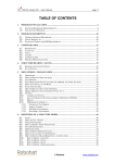
Yagi Mechanical® User’s Manual
and FAQ
(Revised 11/3/15)
Table of Contents
Introduction ...................................................................................... 1
System Requirements ...................................................................... 3
Basic Use for Experienced Designers ............................................. 5
In-depth Listing of All Functions .................................................... 8
The Main Window......................................................................... 8
The Overview Window ............................................................... 11
The Design Window.................................................................... 17
The Edit Tubing Sizes and Costs Window and New Tubing
Category Window........................................................................ 26
The View Window ...................................................................... 29
The Boom Window ..................................................................... 32
The Antenna Wizard ................................................................... 37
The Tubing Select ....................................................................... 40
The Material Window ................................................................. 42
The antenna.ini File ..................................................................... 44
Choosing a Wind Spec ................................................................... 50
Complex Element Design .............................................................. 53
FAQ – Frequently Asked Questions .............................................. 57
Contact Information ....................................................................... 60
Introduction
What is Yagi Mechanical®? Simply put,
it is a user-friendly program created to help you
design antenna elements that hold up to the
stresses of a certain windspeed, and that have a specific resonant frequency. It is best
used in conjunction with a program that can optimize antenna designs for electrical
efficiency. This way, you can use Yagi Mechanical® to start a design, use another
program (i.e. YO, AO, EZNEC, etc.) to refine the design, and apply those changes in
Yagi Mechanical® to verify the mechanical stability of the refinements.
Yagi
Mechanical® even includes the ability to save files for AO and EZNEC and bidirectional transfer of files with YS and YO (so you can import files from those programs
to YM, or export files from YM).
Some of you have experience with this process, and some of you are delving into
it for the first time, but you all have an interest in creating your own antennas, making
them strong and reliable, as well as crafting them to your own personal needs. The aim
of Yagi Mechanical® is to foster that interest, and to make designing antennas as painless
as possible. With the reliability and accuracy of well-known algorithms and similar
programs, in addition to simple interfaces and running in Windows instead of DOS, this
program is made to decrease frustration and increase productivity.
For those of you who have never designed antennas before, you will find it easy
to jump into Yagi Mechanical® and get your designs from your head to the computer
screen. And if you have experience designing antennas already, it should be even easier.
1
To facilitate this, this manual includes both a guide for experienced antenna designers
and a full detail run-down of everything in the program for beginners. So take a look
through this manual, start up Yagi Mechanical®, and be on your way.
2
System Requirements
Yagi Mechanical® uses Java from Oracle (Java is not included on the Yagi
Mechanical® disc, setup will require you install it first from http://www.java.com).
Though Yagi Mechanical® does a lot of calculations, it is relatively minor in needed
resources compared to some of the other Java applications in existence. The minimum
requirements here are based on Java’s minimum requirements, and the recommended
requirements are suggested to run Yagi Mechanical® correctly.
Note: the recommended requirements are quite a bit higher than the minimum, but
that does not mean Yagi Mechanical® will not run if you do not meet the recommended
numbers. In fact, as long as Java will run, Yagi Mechanical® should run. It may run
much slower than on a computer with the recommended specs, but the results are just as
valid for a 200 MHz PII as on a 2.2 GHz P4. However, DXE does not guarantee that
Yagi Mechanical® will work if your computer falls short of the recommended values.
Minimum requirements
-1024 x 768 screen resolution
-266MHz PII class (Core class or better recommended)
-128MB RAM/64MB for XP (1GB RAM or better recommended)
-150MB HD space (250MB HD space or more recommended)
-Windows XP/Server 2008/Vista/7/8
3
A note for Windows 8/7/Vista users
User data and directories have been consolidated and simplified in Windows
8/7/Vista, which is a good thing, but in doing so Microsoft has created quite a few
shortcuts for legacy programs to be able to put things in the right place and it can get
confusing when looking for a file, especially if you are used to the structure in XP. As
part of this, user files are no longer able to be stored in Program Files, and when a
program tries to save them there they instead map to a folder in the User directory.
The directory YM uses can be specified on install or later in the antenna.ini file.
Based on 8/7/Vista’s conventions, a good store directory would be C:\Users\<your
username>\Documents\Yagi Mechanical Files. Or you can ignore Windows’ convention
and do C:\YM Files.
4
Basic Use for Experienced Designers
Yagi Mechanical® is made to be straightforward and intuitive, so some of you
may be able to figure out how to make use of it without any instruction at all. However,
for those of you who are not quite ready to jump in feet first, this section of the manual
will give you a basic idea of how the program can be used without going into
unnecessary detail. If you still require more instruction, or just want to know what
everything does to satisfy your own curiosity, continue on to the next section where each
and every part of the program is covered.
Before you even start it up, it’s important to note that Yagi Mechanical® allows
you to edit the included antenna.ini file (found in
C:\Users\<username>\AppData\Roaming\Yagi Mechanical (Windows 7) or
C:\Documents and Settings\<username>\Application Data\Yagi Mechanical (Windows
XP) ) to somewhat personalize the program. For example, you can redefine the folder
where files are stored, allow YM to update and send error reports automatically, and even
change the extension of the files you save. Excluding the Callsign and Key fields, you
can make any changes you would like, save, and then fire up Yagi Mechanical®.
When you start the program, you will see a splash screen of the YM logo, and then
the Antenna Wizard will be displayed. This is a tool for quickly starting new antenna
designs. Input the desired frequency, windspeed, number of elements, and a tubing size,
and from there Yagi Mechanical® will setup a quick and simple design with all of those
attributes. Basically what you will have is a design with the number of elements asked
for, each with a single section of tubing (of the size selected) long enough to resonate at
the desired frequency. It is not meant to be a viable antenna, but just a starting point that
5
you can work from. You can disable the wizard on startup and/or skip it by pressing the
appropriate button.
After that the Main Window will appear. This window has tabs for each of the
other major windows in Yagi Mechanical®, as well as buttons to select the element you
want to work with in these windows, or to print them out. The Overview Window is the
default tab selected when the program starts. This window includes all of the information
on your antenna design and a simple graphic showing the design, as well as overview
information about each element. Here you can perform file I/O, set windspeed and height
for your design, change units, add notes and a name to your design, and add or remove
elements.
Press the tab to bring up the Design Window, and you will be able to edit the
current element in any way you wish. The main thing to remember is that you have to
press Recalculate (or press enter while your cursor is in one of the tubing fields) to apply
the changes you have made to the section values, or to any of the other fields. With the
other buttons, you can shift the sections up or down, removing the outer section or
making room for more. You can also select a section row where you want to insert or
remove a section, or you can change the material of the selected section or of the element
as a whole.
You can set the windspeed and spec that Yagi Mechanical® uses to calculate
stresses here or in the Overview Window, but you can also use the Minimum Vmax
function to find the breakpoint of your current design. Don’t forget to give your element
a name and a location on the boom before you go.
6
The third tab will lead you to the View Window, where you can take a look at
your design, and print it out as a guide for actually constructing it. Using the Print All
button in the Main Window will allow you to print all of the elements out at once instead
of one at a time.
7
In-depth Listing of All Functions
This section fully details every aspect of the Yagi Mechanical® software. It is
meant as a guide to familiarize you with the software and how it can be used. This is also
a good reference if you are a design veteran looking for something not covered in the
previous section. To keep it simple, this section has been divided into 9 parts: one
subsection for each of the interface windows found in Yagi Mechanical® (Main,
Overview, Design, Cost, View, Boom, Antenna Wizard, Tubing Select, and Material
Windows), and another section devoted to working with the antenna.ini file.
The Main Window
If you have the web update enabled, YM will either prompt you to check for
updates or automatically check on its own. Choosing ‘no’ from the prompt or a lack of
an update will allow YM to run normally. If an update is downloaded, the program will
exit and you will need to restart YM to use the new version. Please read more about web
updates and error reporting in the .ini file section.
After the Yagi Mechanical® splash-screen (and the Antenna Wizard if enabled),
you will find yourself at the Main Window. It serves as a container for the other
windows, and includes a few basic functions that will work regardless of which tab you
have selected.
Below is a listing of all of the buttons and tabs found in this window, along with a
description for each and an image showing where you can find them in the window.
8
1. Go to Element – This button allows you to jump to whatever element is in the
Current Element Field(2).
2. Current Element Field – This field shows which element is currently
displayed in the Design Window and the View Window. You can also type
the element number you wish to go to here, and click Go to Element(1) to
display it.
3. Next Element – This button will display the next sequential element in your
design, or go to the first element if the last element is currently displayed.
4. Previous Element – This button will display the previous sequential element
in your design, or go to the last element if the first element is currently
displayed.
9
5. Print Page – Pressing the print button will print out whatever tab is currently
displayed in the Main Window. The default print style is landscape on
8.5”x11” paper.
6. Print All Pages/Print Project – Rather than cycle through the elements on your
own to print out pages for all of them, this button allows you to print them all
in one shot. The active tab determines the output, so if you are currently in
the Overview Window, just that page will print out. If the Design Window is
displayed, the design page for each element will be printed. And if the View
Window is displayed, the view page for each element will be printed.
Hold control and click the button to use the Print Project function, which
prints out all pages for the file: the one Overview window and then Design and
View windows for each element.
7. Exit – When you are ready to stop using Yagi Mechanical®, use this button to
exit the program. If saving your work was not the last thing you did, you will
be reminded to do so before you exit. Clicking on the ‘X’ on the window has
the same result as using this button. Hold control and click to ‘Quick Exit’,
bypassing the save reminder regardless of the state of the current design.
10
The Overview Window
In the Overview Window, you can load and save files, view information for each
of the elements included in your design, add a name and notes to the antenna, and several
other things. Below is a screen capture of the window, along with a numbered list of
buttons and fields.
1. Current Filename – When you are viewing an existing file, the full path will
appear here. Otherwise, the field will read ‘no file’.
2. Antenna Graphic – This simple depiction of the current antenna is a great tool
for visualizing the layout of the elements on the boom.
11
3. Name Field – Here you can type in a generic or specific name for your
antenna. Separate from the file name, it allows for sub-classing antennas,
which is very useful if you create many similar designs.
4. Notes Field – This field allows you to type in as much or as little specific
information as you wish. In the sample screen, it is used for a date-stamp, and
a note on who designed it. The amount of information you place here is
completely up to you. Anything and everything related to the design is fair
game to make note of here.
5. Element Information Field – Here you will find a listing of the elements in the
current design, including the position on the boom, length, and name for each
element. This field is not editable, but rather displays the current information
the program has stored for your design. Changing the elements in the Design
Window will update the information contained here.
6. Element Select – This drop-down list allows you to select any of the existing
elements in the current antenna design. Selecting an element displays the
resonant frequency in the Frequency Field (7), and applies presses of the edit
buttons (10,14,17) to the selected element.
7. Frequency Field – This box displays the resonant frequency for the selected
element (6). This is the same value you would find for the corresponding
field in the Design Window, and is a convenience so you do not have to
switch windows to determine the frequencies of each element. See the
Resonant Frequency Field in the Design Window section for information
about how this value is calculated.
12
8. Unit Select – This menu allows you to switch between inches and millimeters
for the base unit of your design. Note: Yagi Mechanical® is preferably run in
English units, and has been run and tested much more thoroughly using said
units. However, Metric units have been accurate in tests and should work fine
for those of you who are more comfortable with them. Your feedback on
improving this aspect of the program for Metric users is welcomed.
9. Filetype Select – This menu allows you to choose what type of file you want
to open or save to. This feature is meant to be a convenience, not a direct
implementation of the routines in the other programs; it is not guaranteed to
work with all files or versions. Basically opening or saving with a non-YM
filetype is viewing or saving the information just as could be done by hand,
but it is done much more quickly and efficiently. Please read through the
following information about the non-YM filetypes below before you use this
feature:
a. YS File – Open and Save both function well. Boom designs DO NOT
transfer between programs.
b. YO File – Open and Save both function well. Specially designed to
work better for designs that are started in YM, tested electrically in
YO, and then reopened in Yagi Mechanical®.
c. AO File – Only the Save function works. This is recommended only
for advanced users, as symbolic notation used in AO is not produced
by YM, and must be added manually before the design can be properly
tested in AO.
13
d. EZNEC File – Only the Save function works. This is recommended
only for advanced users. Regular EZNEC files are encoded, and as
YM and DXE have no affiliation with the program or its designers,
Yagi Mechanical® uses an alternate input to transfer the design. The
output from YM is a .TXT file of wires (not info about power sources
or ground; these must be done manually in EZNEC). The .TXT file
can be input by EZNEC into an existing design.
10. Design Element Button – Pressing this button will open the element selected
in (6) in the Design Window (see the next subsection for more).
11. Windspec Select – This menu allows you to choose the method used for
calculating wind stresses on your design. See the section Choosing a Wind
Spec for more information on the included items.
12. Design Boom Button – This button brings up the Boom Window and allows
you to view and/or change the current boom design.
13. Open/Reopen Button – This button brings up a file dialog, allowing you to
choose a file to open in the Overview Window. The type of file opened is
determined by the Filetype Select, and the default directories for each program
can be set in the antenna.ini file. Holding Ctrl and clicking the button will
reopen the current file. Note: the default extension for Yagi Mechanical®
files is .STM.
Note: If there is a difference in windspeed and spec between the values
currently in use and what is stored in the file, you will be prompted with a
14
dialog that will show both sets and allow you to choose which you want to use
going forward.
14. New Element Button – This button will create a new element for your design
and pass it to the Design Window so you can edit it. To aid in the design of
antennas with similar elements, the previous element will be copied into the
new element, providing a starting point for the design.
15. New Boom Button – When you want to design a new boom for your antenna,
you can use this button in combination with the Boom Sizes(20) to create a
simple boom for a starting point, which you can edit to fit your needs. This is
a very simple function that makes a boom long enough to accommodate the
locations of all of your elements, using a wall thickness of 0.058” and a 2” or
3” diameter.
16. Save/Quicksave Button – Record your design to a file for future use, or export
it to another program by pressing this button. The type of file saved is
determined by the Filetype Select, and the default directories for each program
can be set in the antenna.ini file. Holding Ctrl and clicking the button will
quicksave the current file. Note: the default file extension for Yagi
Mechanical® is .STM.
17. Remove Element Button – To remove an element from the current antenna
design, select it with (6) and then press this button. Note: there is no ‘undo’
command for this action, so saving your design is suggested before making
such a change to your design.
15
18. Windspeed Field – Displayed here is the windspeed for which Yagi
Mechanical® will calculate wind stresses on your design. The default is
100mph, but you can adjust it to fit your needs.
19. Height Field – The height of your antenna above the ground is displayed here.
This number is used for some of the wind specs to better calculate element
survivability. When the spec selected uses this value, the Height Field will
have a white background. Otherwise, it will have a gray background.
20. Run Wizard Button – This button causes YM’s Antenna Wizard to run. Read
more about it in the corresponding section of the manual. Note that running
the wizard and creating a new antenna will overwrite the current design, so
save any important work before pressing this button.
21. Bill of Materials Button – Press this button to display a listing of the total
length of each size of tubing needed for your current design, as well as a list
of every unique piece of tubing needed by size. Includes a print button to
have a hard copy of both lists.
22. Display YM User Manual – This button will launch the help file you are
currently reading.
23. Boom Sizes – Selecting one of these and pressing the New Boom Button(15)
will cause Yagi Mechanical® to create a boom design to fit the current
elements on your antenna.
24. Print Notes Button – Use this button to print out the notes for your current
design. The output is a simple one-page printout that includes the filename
16
The Design Window
This window is where you will design and modify the elements on your antenna.
It can be reached by pressing the Design Element or New Element Buttons in the
Overview Window, or by clicking the Design Window tab. The Design Window
displays all of the information about the selected element, and allows you to edit the
element directly. All 40 possible sections of an element can be edited here, either with all
sections visible or with the left hand side of the window as a scrollable pane. You can
change this setting in the Antenna Wizard, and the setting will be saved so you already
start in your preferred mode the next time you run YM.
Below are a sample screen of the Design Window, and a list of all of the fields
and buttons. Note: The fields on the left half of the Design Window (1-7) can be
navigated via the keyboard either by tabbing through them sequentially or by using the
arrow keys to move up, down, left, or right. As you navigate between different sections,
the Section Select will automatically update to reflect the number of the section you are
currently editing.
17
1. Diameter Field(s) – These editable fields display the diameter for each section
of the element. Color changes to blue to show cost is estimated for that tubing
size, or red to show that the section is not included in the current cost estimate
(see Cost Estimation Type(18) for more info).
2. Wall Field(s) – Shown here are the wall thicknesses for each section. The
default value is 0.058”, and it is inserted for you when you add a new section,
or you can change it to reflect the size of tubing you would like to use to
construct your design.
3. Exposed Length Field(s) – The exposed lengths for each section in your
design are displayed here. Change these to alter the element’s resonant
18
frequency. Since wavelength and frequency are inversely proportional, add
more length to lower the resonant frequency or shorten the element to increase
the frequency.
4. Total Length Field(s) – These fields show the overall length of each section,
including the exposed length, as well as the overlap between sections. You
can change the overlap via the Overlap Field(s) (6) and the total lengths will
be updated accordingly. Or you can directly edit these fields by changing the
Edit Select(22).
5. Material Field(s) – Here you can change the yield stress of the material your
tubing is going to be made out of. The default value here is 35000 psi, the
yield stress of 6063 aluminum. Another common value is that of 6061
aluminum at 40000 psi. These can also be changed via the Material
Button(25).
6. Overlap Field(s) – The amount of overlap between different sections of tubing
can be set here. Note: Yagi Mechanical® does not include preset values for
overlaps of specific tubing, but the following minimum values are
recommended - 4 inches for tubing 2" or larger, 3 inches for tubing 1" to 2",
and 2 inches for tubing smaller than 1".
7. Stress Field(s) – The calculated wind stress for each section is displayed here.
If a value here is larger than the yield stress defined in the Material
Field(s)(5), it will be highlighted in red to show that the element will be
overstressed for the set parameters. The stress values are calculated based on
19
the following: Windspeed (8), Diameter, Wall, and Exposed Length Fields (13), Material (5,25), wind spec and height (20-21, also see Overview Window).
8. Windspeed Field – Listed here is the windspeed for which the element stresses
are being calculated. Set the desired speed here or in the Overview Window.
If you use the Minimum Vmax(19) option, the maximum speed for which all
sections are below stress is displayed here. Uncheck the box and the speed
will return to the same as what was previously.
9. Design Frequency Field – Here you will find the resonant frequency of the
current element previous to any changes you have made to it since getting to
the Design Window. This feature is useful for remembering what frequency
you started at, without having to re-open the antenna or write it down on your
own.
10. Resonant Frequency Field – The resonant frequency for an element is
determined based on the length of tubing and the resistivity of the material
used. This field shows the resonant frequency calculated for the current
element design. Use this to fine-tune your element for the desired frequency.
11. Location – This refers to the location of the element on the boom starting from
the reflector end.
12. Element Name Field – You can enter a descriptive name for this element, or
modify the existing name from the Element Information Field in the Overview
Window.
13. Total Weight Field – This shows the total weight for the current element
design.
20
14. Total Length Field – The overall length of the element is shown here.
15. Area Field – This field displays the total cross-sectional area for the element.
Note: (13-16) apply to the entire element, not the half-element shown in the
Design Window.
16. Cost Field – Displayed here is the estimated cost of the tubing for your
element design. You can also click the arrow to drop down a list of what
prices are used per section of tubing.
Please note that this is merely a calculation based on given tubing sizes and
costs, it does not account for other pieces needed to construct the antenna, nor
does DX Engineering guarantee that the default values in Yagi Mechanical®
are in line with current costs of tubing.
17. Edit Tubing Sizes and Costs Button – This button displays the Edit Tubing
and Costs Window (see the corresponding subsection), which allows you to
add and change tubing types and sizes stored in the tubing.txt file.
18. Cost Estimation Type Select – Changing the selected value here will alter how
Yagi Mechanical® determines the cost of your design. Each choice is
detailed below. The method you choose is stored by YM and reloaded the
next time the program is run.
Use existing price/ft and:
-
No extrapolation for tubing with no cost – This ignores tubing
without a set price, giving you an estimate based only upon
tubing prices you know. The Diameter Field(1) for tubing left
out of the calculation is painted red to show this.
21
-
Use average price/ft of other tubing pieces – This uses the
average per foot price of the tubing in the rest of your design
and applies it to sizes without a cost. The Diameter Field(1)
for sections using this average is painted blue to show this.
-
Use average price/lb of other tubing pieces – This uses the
average per pound price of the tubing in the rest of your design
and applies it to sizes without a cost. The Diameter Field(1)
for sections using this average is painted blue to show this.
-
Use 6063 price/lb – This uses the average per pound price of
6063 tubing of the same diameter and applies it to sizes
without a cost. The Diameter Field(1) for sections using this
average is painted blue to show this.
19. Minimum Vmax – Using this option allows you to see the maximum wind
speed for which all of the sections in your design are below the maximum
stress. Generally you would use this to see the upper limits of an existing
design. Unchecking this option returns the windspeed to what it was
previously.
20. Wind Spec Select – This menu allows you to choose the method used for
calculating wind stresses on your design. See the section Choosing a Wind
Spec for more information on the included items.
21. Height Field – The height of your antenna above the ground is displayed here.
This number is used for some of the wind specs to better calculate element
22
survivability. When the spec selected uses this value, the Height Field will
have a white background. Otherwise, it will have a gray background.
22. Edit Select – This selector allows you to switch between editing the exposed
lengths of the tubing in your element to editing the total lengths. Editing the
total lengths of the tubing is useful for keeping the tubing sections to a certain
length if they are to be ordered/shipped and have a maximum acceptable
length.
23. Shift Up Button – This button is the equivalent of removing the tip section of
the current element. The rest of the sections will be shifted up a row in the
display.
24. Section Select – This menu allows you to select a section to perform an action
on. You can also select Element to apply the action to the entire element.
Valid actions for sections: (25, 27-28). Valid actions for Element: (25). Note:
the selected section will update itself automatically as you traverse and edit
the sections in your design.
25. Material Button – This button will open the Material Window (see the
corresponding subsection). The changes made will be applied to the section
selected in (24), or to the entire element if Element is selected in (24).
26. Shift Down Button – Pressing this button shifts all of the current sections
down a row so that a new section can be placed on the end of the element.
27. Insert Section Button – This button will shift down all of the sections from the
selected spot (24) down, making an empty row where you can define a new
section. This causes the Tubing Select to be displayed, and you can use it to
23
select a specific size of tubing, or simply copy the previous tubing size. Read
more about this in the corresponding section of this manual.
28. Remove Section Button – After selecting a section with (24), it can be
removed from the design by pressing this button.
29. Recalculate Button – The button takes all of the values and options you have
set in the Design Window and uses them to calculate the stresses of each
section in the design. Most of the buttons will ‘call-in’ a click to this button
when they are finished with their own task, but if you change any of the fields
you will have to press the Recalculate Button for the changes to take effect.
30. Ice Thickness Field – This field allows you to test your design’s ability to hold
up to wind stresses when it has a layer of ice on it. Specify whatever radial
thickness of ice you would like to test it at and hit the Recalculate Button(29).
Or you can set it to zero to go back to regular calculations.
31. Element Support Distance Field – Depending on how you plan on
constructing your element, you might want to specify how far from the boom
the element is supported. Change the value to represent this, and use the
Recalculate Button(29) to see the effects on the section stresses. Note that this
will only affect the element from the boom out to the distance of the support
length; sections past this will not see a change in wind stress. Set back to zero
to ignore any extra support distance.
32. RForce Field – The RForce, or resultant force, is the total force the boom sees
from the element when the wind is at the specified speed. Shown below is
one of DXE’s BEB-2’s being tested with extreme force. The arrows show
24
how the resultant force is acting on the bracket. Note that whatever apparatus
you are using to mount your elements must withstand this force. Find out
more about DXE brackets at http://www.dxengineering.com.
33. RMoment Field – The RMoment, or resultant moment, is the total moment
that is exerted on the boom by the element when the wind is at the speed
specified. Shown below is one of DXE’s BEB-2’s being tested with extreme
force. These forces create a moment along the element, and their total at the
end of the element is the resultant moment. The arrows show how the
resultant moment is acting on the bracket. Note that whatever apparatus you
are using to mount your elements must withstand this moment. Find out more
about DXE brackets at http://www.dxengineering.com.
25
34. Total Sag / Displacement Field – This field shows the amount of vertical sag
for the element relative to the height of the center of the element. By clicking
the drop down list and selecting displacement instead, the field will show the
amount of horizontal displacement for the element relative to the position of
the center of the element.
The Edit Tubing Sizes and Costs Window and New Tubing Category
Window
When you click on the Edit Tubing Sizes and Costs Button in the Design
Window, this new window is displayed. From here, you can change stored prices and
sizes of tubing, review the different categories of tubing available to build your design,
and even easily create new types and sizes of tubing material to use throughout Yagi
Mechanical® (via the New Tubing Category Window). This data is stored in the
tubing.txt file in your YM directory.
26
See the image and descriptions of both windows and their functionality below.
Note: The fields in the scroll pane of the Edit Tubing Sizes and Costs Window (5-7) can
be navigated via the keyboard either by tabbing through them sequentially or by using the
arrow keys to move up, down, left, or right.
1. Category Select – This menu allows you to see all of the existing category names.
Choose a category to display information about its material, sizes, and prices.
27
2. New Category Button – Use this button to bring up the New Tubing Category
Window (see items 10 – 18). The subwindow displayed will allow you to define
a new tubing category for use in Yagi Mechanical®.
3. Density Field – Here the material density for the current category is displayed.
Units for this and the other fields (4 – 7) change automatically to Metric if the
category is defined as such.
4. Yield Stress Field – The current category’s yield stress is shown here.
5. O.D. (Outside Diameter) Fields – Review current tubing diameters for the
selected category in these fields. Or define new sizes starting in the first blank
row.
6. Wall Thickness Fields – Same as (5), but shown here is the wall thickness for
each tubing size.
7. Price per Foot Fields – Review or enter in per foot pricing for tubing sizes here.
The default values in Yagi Mechanical® are taken from TexasTowers.com.
8. Save Button – Clicking this button will save any new tubing sizes defined in the
fields (5 – 7) and store any new categories defined in the New Tubing Category
Window. It will also close the Edit Tubing Sizes and Costs Window and save the
stored tubing data to the tubing.txt file.
9. Cancel Button – This button closes the window and discards all changes and
additions.
10. Category Name Field – Enter in the name for your new tubing category here. It
must be different from the existing categories.
28
11. Use Metric(/English) Units Button – Toggle between English and Metric units by
clicking this button. Labels for the fields (12 – 16) will change accordingly.
12. Yield Stress Field – Set the yield stress of the new category here.
13. Density Field – The density of the new tubing type is entered here.
14. Diameter Field – To make your new category, you have to define a starting tubing
size. Yagi Mechanical® will arrange new tubing sizes added in the Edit Tubing
Sizes and Costs Window according to diameter size, smallest to largest. Enter the
first tubing’s outside diameter measurement here.
15. Wall Thickness Field – The tubing thickness should be typed in this field.
16. Price per Foot Field – Set the per foot price of your tubing size here. If you do
not have a price, set it to zero and use Yagi Mechanical®’s different options to get
a cost estimation of your design.
17. Create Button – Pressing this button will save the data you have entered for the
new category temporarily. You MUST click the Save Button(8) in the Edit
Tubing Sizes and Costs Window to permanently save your new category to the
tubing.txt file and use it in your designs.
18. Exit Button – Click this button to discard your entry and return to the Edit Tubing
Sizes and Costs Window without creating a new category.
The View Window
The third and final window embedded in the Main Window is the View Window.
Here you can see a visual representation of the design you have created. With the
29
number of variations in antenna design, it is difficult to take the information from every
design possible in the Design Window and figure out what they would look like. Yagi
Mechanical® accounts for the most common configurations, and shows a cross-sectional
half of the tubing, which indicates sizes, overlaps, and gives a visible display of how the
element pieces fit together. Read the Complex Element Design section for more
information and tips about how to accurately describe your design using Yagi
Mechanical®.
Below are a screenshot of the View Window and a description of the things you
will find in it.
1. Filename – Displays the full path of the current file. Reads “no file” if you
have not saved your design.
30
2. Timestamp – To help keep track of when you printed out the elements in your
design, the View Window automatically includes a timestamp of when it was
displayed.
3. Section Drawing – The red boxes basically represent a cross-section of the
element, but just the top half, so things are not too cluttered. The view starts
from the center of the element and works outward towards the tip as you move
to the right. Elements with more than 3 or 4 sections are split up and
displayed in two drawings to keep everything clearly visible.
4. Length and Width – For each section of the element, the length and width of
the tubing is displayed either above or below the Section Drawing.
5. Outer Diameter – The outer diameter of the tubing is displayed inside of the
Section Drawing.
6. Overlap – For sections that overlap with the previous one, the Section
Drawing will indicate the overlap graphically, and the amount of the overlap
will be displayed beneath the drawing. Note that these lengths are not added
to the Length and Width also displayed; you must consider the two lengths
separately.
7. Abbreviation List – To keep things simple, there is a listing of what each
abbreviation used in the View Window corresponds to.
31
The Boom Window
An important part of antenna design is creating a solid base to support your
elements. Yagi Mechanical® includes a useful Boom Window to help with this. It tests
the boom in the same way that the elements are tested, but instead of just wind stresses, it
takes into account the weight and position of each element on the boom. Beyond that, it
allows you to balance the boom for both weight and torque, and also calculate the amount
of offset torque that needs to be taken into account for mounting to a mast.
There are two different ways to get to this window (both are outlined in the
Overview Window section). The first is the Design Boom Button, which will open
whatever existing boom is linked to the current antenna. If there is nothing there, the
Boom Window will open up with empty fields and you can start the boom design from
scratch.
The other way to bring up the Boom Window is to select a size (2” or 3”), and
press the New Boom Button. This will take the current information from the antenna
design and create a simple boom for you, which can be modified until it is adequate for
your needs. All that this function does is create a boom of the size you selected, with a
wall thickness of 0.058”, and a length long enough to accommodate all of the elements.
Note that using this feature will overwrite any existing boom design, so it is
recommended that you save a backup copy of the design before using it.
32
The interface of the Boom Window is very similar to that of the Design Window,
so if there’s an item you see in the screenshot not covered in this section, check out the
information about the same items in the Design Window section. The differences and
new items are listed below. Note: The fields in the scroll pane to the left side of the
Boom Window can be navigated via the keyboard either by tabbing through them
sequentially or by using the arrow keys to move up, down, left, or right.
1. Mast Checkbox – This allows you to pick where on your design the boom will
be anchored. Because the boom may or may not be uniform, you design the
whole thing in the Boom Window, as opposed to the half elements in the
Design Window. Check the box in between the two sections where you
would like to mount your boom.
2. Section Scrollbar – The portion of the Boom Window that displays the boom
sections shows 10 sections at a time. Use the scroll bar to view any 10 of the
total 20 available sections.
33
3. Support Distance – Reflector Side – Similar to the Element Support Distance
in the Design Window, this field allows you to specify how far from the mast
your boom is supported on the reflector end. Use this to get an idea of how
adding guys or trusses may help your design.
4. Support Distance – Director Side – Similar to the Element Support Distance in
the Design Window, this field allows you to specify how far from the mast
your boom is supported on the director end. Use this to get an idea of how
adding guys or trusses may help your design.
5. Change Mount Point Step Field – Input the step amount to be used in
conjunction with the Towards Refl. and Dir. Buttons (6 & 7).
6. Towards Reflector Button – Use this button to move the boom’s mount point
towards the reflector end of the boom. The distance moved is specified in the
Change Mount Point Step Field (5).
7. Towards Director Button – Use this button to move the boom’s mount point
towards the director end of the boom. The distance moved is specified in the
Change Mount Point Step Field (5).
8. Plate Thickness Field – Yagi Mechanical® allows for using a square plate to
torque balance your boom. Input the thickness of the plate you will use.
9. Plate Density Field – Input the density of the material you will use for your
torque balancing plate. The standard density for aluminum plate (6061 or
6063) is 0.0975.
10. Weight Balance Field – While designing your antenna, it is important to
balance the weight on the boom. Yagi Mechanical® will automatically
34
calculate the weight that can be added to the tip of the light end of the boom to
balance the antenna. A positive value in the Weight Balance Field means the
weight goes on the reflector end of the boom, a negative value indicates that it
goes on the director end.
When YM has calculated the size of a torque-balancing sail for you, it will
include the weight of the sail when determining the weight balance. When
the sail and extra weight go on the same end of the boom, you know that
their combined weight is equivalent to the weight needed to balance the
boom. This makes for an easy shortcut if you do not know what material
you want to make your sail out of: enter ‘0.0’ for the plate density, weigh
your plate when you make it, and subtract that value from the weight
balance to determine the extra weight needed.
11. Sail Size Field – Yagi Mechanical® displays here the size of the square sail
needed to torque balance the antenna. This value is calculated using the
numbers input in the Plate Thickness Field and the Plate Density Field. Since
torque balancing is based on area, a sail shape other than a square may be
used, as long as its area is equivalent to the value in the Sail Size Field
squared. Also, knowing that the side with the lesser area is where the sail
should be mounted, a constant diameter boom’s sail will always go at the end
of the shorter side.
12. Boom Offset Field – When creating your antenna design, wind stresses
produce torque via both the boom and the elements. Torque on the boom can
be countered with a torque balancing plate or sail (see 4,5, and 7 above).
35
Torque on the antenna from the elements is a concern if the center of the
boom is not above the middle of the tower. Input the distance from the center
of the boom to the center of the tower in the Boom Offset Field, and the
resulting torque is displayed in the Offset Torque Field.
13. Offset Torque Field – This field displays the torque on the antenna from the
offset of the boom from the tower. This value is the amount of torque that the
boom mounts must support.
14. Reflector End Sag – Same function as the Total Sag Field in the Design
Window, but it shows the sag just for the reflector end of the boom.
15. Director End Sag – Same function as the Total Sag Field in the Design
Window, but it shows the sag just for the director end of the boom.
16. Print Button – Use this button to print out the Boom Window. Default output
is in landscape orientation.
17. Exit Button – Use this button to save the changes you have made and go back
to the Main Window. Note that you can bring up the Main Window while the
Boom Window is open, which is helpful for seeing what the elements in your
design are, but DO NOT change anything in it while the Boom Window is
open.
36
The Antenna Wizard
This is a simple window allowing you to set a few options and let Yagi
Mechanical® quickly make a starting point for your new design. The Antenna Wizard
will show up the first time you run YM, right after the splash screen, and every time you
start the program if enabled. It is also accessible via the Run Wizard button in the
Overview Window. You can disable the show on startup option whenever you are in the
wizard. See the following screenshot and descriptions for more information about how to
use the wizard.
1. Frequency Checkbox/Field – Set your desired resonant frequency here and
click the checkbox to enable it. When unchecked, the Antenna Wizard will
default to 14 MHz.
37
2. Number of Elements Checkbox/Select – Choose the number of elements for
your design and make sure the checkbox is selected. The default number of
elements is one.
3. Tubing Diameter Checkbox/Field – Input the starting diameter (smallest
tubing size) for your new design, or leave it as the default, 0.5”.
4. Windspeed Checkbox/Field – Set the windspeed you want to build your
antenna to withstand here. The default is 100 mph.
5. Unit Select – Use these menus to switch between English and Metric units.
6. Create Antenna Button – Press this button to feed all of your input into Yagi
Mechanical so it can give you your new base design. The output of the
Antenna Wizard is a simple antenna with single section elements of the tubing
size you selected made to resonate at the selected frequency. Quite a bit of
work will be necessary to get this design to a viable antenna, but using the
wizard makes it easy to start a new design rather than going from scratch or
deleting all of the data already in YM from another design.
7. Skip Wizard Button – Use this button to bypass the Antenna Wizard
completely and keep whatever current design is in YM.
8. Scrollable Design Window Checkbox – Checking this will display the 40
sections in the Design Window as a scrollable pane rather than all in the
window at a smaller size. This is useful if you have a lower resolution display
or do not use all of the available sections when designing your elements. This
setting is saved across sessions, so YM will display the sections whichever
way you prefer when you reopen it.
38
9. Show on Start Checkbox – Checking this box will tell YM to display the
Antenna Wizard every time it starts up.
39
The Tubing Select
This window will be displayed when you click on the Insert Section Button in the
Design Window. It allows you to select from a large list of common tubing sizes used in
antenna construction. You can also copy the previous section and modify that.
Tubing sizes can be added or changed via the Edit Tubing Sizes and Costs
Window(see the corresponding section of this manual). This data is stored in a text file
in the YM directory called tubing.txt which can also be edited directly. Shown below is
the format of these entries. Follow the same format (category name, units, density/yield
stress, and then outer diameter and wall thickness) to enter in new tubing.
[Schedule 40 6063][english][d=0.0975;s=35000]
OD=0.840; T=0.109;
Below are a screenshot of the Tubing Select and a description of each part.
1. Category of Tubing Select – Choose a category here to have tubing from that
category displayed in the Size Select.
40
2. Size Select – Select a specific size of tubing here to fill the fields for where
you want a new section inserted.
3. Use Selected Tubing Button – Press this button to have YM insert the selected
size of tubing into your design.
4. Copy Previous Section Button – If you do not want to use one of the available
tubing sizes, press this button and YM will copy the previous tubing size,
which you can edit manually to get what you want. A blank row is the result
if you close the Tubing Select via the ‘X’ button.
41
The Material Window
This subwindow is reached by pressing the Material Button in the Design
Window or the Boom Window. From here you can change the yield stress and/or density
of the material used for the selected section or for the entire element.
Below are a sample screen and a description of the components in this window.
Note: the default material properties for all new elements and sections are the same as the
material properties of 6063 aluminum (the same as in the picture above). Another
common material is 6061 aluminum (yield stress of 40000 psi, density of 0.0975 lb/in3).
1. Yield Stress Field – Enter in the yield stress for the material you want to make
your element out of.
2. Density Field – Input the material density you want to use for your element.
3. Save Button – Pressing this button will apply the changes in yield stress and
density to the selected section or the entire element. Note: changing the
42
material for the entire element will overwrite changes made to individual
sections.
4. Cancel Button – To ignore any changes to the material values and to exit the
Material Window, press the Cancel Button.
43
The antenna.ini File
Yagi Mechanical® uses a simple .ini file to load some variables and operate
correctly. Though there are some comments about the different entries in the file right
inside antenna.ini, this subsection is meant to be a more thorough explanation and you
should not edit the file without reading through it.
Simple layout of the antenna.ini file (excluding comments):
yMf = *.stm
yOf = *.yag
ySf = *.ys2
aOf = *.ant
eNf = *.txt
yMd = C:\\Users\\<username>\\Documents\\Yagi Mechanical Files
yOd = C:\\YO
ySd = C:\\YS
aOd = C:\\AO
eNd = C:\\Program Files\\ezw\\ant
pr0 = 0.096
pr1 = 0.058
pr2 = 0.067
pr3 = 0.075
44
pr4 = 0.083
pr5 = 0.092
pr6 = 0.100
pr7 = 0.113
pr8 = 0.129
pr9 = 0.146
pr10 = 0.163
pr11 = 0.188
pr12 = 0.208
pr13 = 0.229
pr14 = 0.250
WebUpdate=
ErrorReporting=
Callsign=
Key=
1. yMf – This is the file extension that Yagi Mechanical® brings up in the
open/save file dialogs. The default is *.stm. Please note that there is no hardcoded filter for filenames. If you open a file with a different extension, Yagi
Mechanical® will try to open it, but unwanted operation or a crash may be the
result. The same reaction can be expected if you modify the actual files
outside of the program. The format may seem straightforward, but even
adding an extra line in the wrong place may make the file unreadable to Yagi
45
Mechanical®. So what is the upside to this? You can use whatever extension
you want for your Yagi Mechanical® files. *.stm is not a common extension,
so you should not have to change it, but in the event that you need to do so
you can.
2. yOf – Filetype for Yagi Optimizer files.
3. ySf – Filetype for Yagi Stress files.
4. aOf – Filetype for Antenna Optimizer files.
5. eNf – Filetype for EZNEC files.
yMd – Here you will find the current directory for the saved files, and the default
directory that Yagi Mechanical® attempts to find files in. This can be changed to
whatever folder you wish as long as you make sure that a) the directory exists and b) you
use double backslashes to create the path (to make the path readable for Java). yMd will
be C:\\Users\\<username>\\Documents\\Yagi Mechanical Files (Windows 7/Vista) or
C:\\Documents and Settings\\All Users\\Documents\\Yagi Mechanical Files (Windows
XP) unless you change it manually.
6. yOd – Yagi Optimizer file directory.
7. ySd – Yagi Stress file directory.
8. aOd – Antenna Optimizer file directory.
9. eNd – EZNEC file directory.
10. pr0-pr14 – In some of the cost estimation of your design, Yagi Mechanical®
can use these standard prices of 6063 aluminum tubing. The prices start at
0.25” tubing at 0.058”, and go up by 0.125” outside diameter. Tubing that is
exactly one of these sizes will pull the cost directly, while other sizes will be
46
estimated based of cost/weight ratio of similar size tubing. The accuracy of
the cost estimate is variable and is not meant to be a definitive cost analysis,
but as the name implies, an estimate of what it might cost. It does not include
anything but the actual tubing, so your antenna WILL cost more than the
amount shown in Yagi Mechanical®.
11. WebUpdate – Yagi Mechanical® allows for updating to the latest version of
the program using the internet. There are three settings for this option: yes,
no, and ask. When set to ‘yes’, YM will automatically check for a new version
every time you run the program. If set to ‘ask’, you will be prompted to check
for a new version if you are running a build that is more than 3 months old.
Setting WebUpdate to ‘no’ will not prompt you or check for updates at all.
To get the most out of Yagi Mechanical®, it is recommended that you
allow the program to check for updates periodically. If your PC is on a
broadband connection, it is suggested that you set WebUpdate to ‘yes’, or
‘ask’ if you prefer to know when YM is checking for updates. If you use a
dial-up connection, or any internet connection that is not always on, it is
suggested that you use the ‘ask’ option, so that you can enable your
connection when you want YM to check for new versions.
12. ErrorReporting – While Yagi Mechanical® is a very solid program and has
been improved through several versions, we at DX Engineering realize that
our debugging process may not catch every flaw in the program before it gets
to your computer. To simplify things for the consumer and DXE, YM now
47
includes the ability to report errors directly to us, giving us useful information
that can be analyzed and will allow us to fix the problem promptly.
The same settings apply as for the WebUpdate: ‘yes’ allows automatic
error reporting, ‘no’ disables it, and ‘ask’ will prompt you before sending
error information to us. The only difference is that the ‘ask’ setting will not
prompt based on the time that has passed since last used, but instead relies on
actual errors encountered while running Yagi Mechanical®.
Allowing YM to report errors is not a threat to your computer’s security or
an invitation for spam or malware. The only information that is sent to us is
information directly from the program regarding the reason it had a problem.
No data about your PC or stored information about you on your PC will be
sent to us. That is because we are not collecting information about you, but
about the use of our program, and only for the purpose of making it better for
you, the user.
13. Callsign – The entry here determines what is shown in the title bar when you
run Yagi Mechanical®. Though it is labeled ‘Callsign’, it can be your name
or your company’s name if you wish. See the note below about changing the
Callsign.
14. Key – This is the registration key given to you upon your purchase of the Yagi
Mechanical® program. Yagi Mechanical® WILL NOT WORK unless you
have a valid Key.
48
Important note: Callsign and Key should not be changed. When you installed
Yagi Mechanical®, you input the values given to you at purchase. These are the only
values that your copy of Yagi Mechanical® is guaranteed to work under. If you wish to
change what is displayed when you run the program, please contact us at
[email protected] to get a new Callsign/Key pair that has been verified to
work correctly.
49
Choosing a Wind Spec
So you have the Yagi Mechanical® program, you are ready to design an antenna,
but what is this ‘Wind Spec’ thing all about? Which one should you choose? Is it
important to your design? With this quick read-through, hopefully all of your questions
will be answered.
Let us start with the question ‘Is this important to your design?’ The answer: it
depends. If you live in an area with relatively low wind speeds and very little gusting,
and you are designing an antenna to sit on a 30-foot pole, then the wind spec you choose
will probably not make much of a difference in your design. But if you live on the outer
banks, in tornado alley, or anywhere else that gets a lot of high-speed wind, then it is very
important to your design. Most likely, you fall somewhere in between, so keep reading
and you can pick a wind spec that suits your needs whether they are big or small.
What is a Wind Spec? Spec is short for specification, or in other words, a set of
guidelines. There are several specifications in Yagi Mechanical® for choosing how to
account for the effect the wind has on your antenna when you get it up on top of a tower.
No Wind Spec is equivalent to placing your antenna in a wind tunnel, with a steady
windspeed. This neither accounts for anything special in real world conditions, nor does
it do any more than say “if you design your antenna for 90 mph winds with this, it will
generally hold up under conditions where the wind does not reach that speed.” More than
likely, if you are designing an antenna for your own personal use and you design it for
100 mph in an area where the gusts never reach 100 mph, then No Wind Spec should be
fine.
50
EIA-222-C is the next step up. It still does not take into account factors like
height, but it is based on real wind situations and can be used with maximum speeds from
different zones (Zone A = 86.6 mph, Zone B = 100 mph, Zone C = 111.8 mph) to be even
more accurate. So if you live in zone A and design at 90 mph with EIA-222-C, you can
be pretty sure that your antenna will hold up. Most of the U.S. is in zone A, with most of
the Atlantic and Gulf shores, the northern great plains, areas west of Lake Michigan,
western Washington state, and parts of northern California in zone B, and south Florida
and east North Carolina in zone C. Note that although this spec is included in Yagi
Mechanical®, its use is not recommended because it is virtually an obsolete spec.
If you want a more detailed calculation, take another step up and use the UBC-97
spec. This is a very flexible spec, and useful if you want to factor in geographical
features, height, and windspeed. By choosing a wind exposure level, you can use UBC97 to get results much more applicable for your location. The different wind exposures
are defined as the following: Exposure B is a site with 20% or more of the surrounding
mile of land covered by buildings, forest, or anything else which impedes the wind;
Exposure C is a mostly flat and open site, with ½ mile or more empty terrain surrounding
it; Exposure D is a site with basic wind speeds of 80 mph or more, and has a large body
of water nearby, and unobstructed.
The last wind spec is EIA-222-F. It is much like EIA-222-C, but it takes the
height of the antenna into consideration, resulting in a much more conservative design.
But it has the added advantage of using maximum speeds according to counties rather
than the generic zones. A listing of these speeds can be found at
http://www.wirelessestimator.com/windspeeds.cfm.
51
So which wind spec should you choose? The decision is yours. The most hasslefree choice is to use No Wind Spec. You get totally worthwhile results without having to
worry about what zone you are in or how high you plan to mount your antenna. But if
you want results that are more accurate and localized, the EIA and UBC specs are a better
fit.
52
Complex Element Design
In order to make designing your antennas easier Yagi Mechanical® includes the
View Window, a visual representation of the elements. This is useful for seeing how the
sections fit together, as well as a guide for actually constructing the elements when you
get to that point. But the View Window can handle more complex designs than just ‘one
section overlaps with the next and fits inside it’. In this section, several different, more
complex types of multiple-section combinations will be outlined. You may or may not
find it necessary to use them, but knowing they exist will give you a wider range of tools
to use when designing antennas.
For each type of combination there is a sample picture of what the View Window
displays and the corresponding list of values used in the Design Window to create it. The
multiple walls are very useful for making stronger sections without having to find or buy
thicker tubing. The sleeves are useful for elements that might have to be disassembled,
or to use a solid piece to connect to the boom (as shown in these examples).
The previous section is shown on #2 to illustrate that any of these combinations
can have an overlap if desired. This example shows an overlap for each of the sections
involved, but the value for the section closest to the boom is the one used. Note that all
involved sections in a combo must have the same or less overlap than the first section.
This can also be used in the opposite way to prevent Yagi Mechanical® from making a
53
combo out of two sections when you are using thicker tubing and not doubling up
sections.
While these combinations will cover a lot of different antenna designs, they are
not all-inclusive, and are not meant to be. The thing to remember is that regardless of
what you see in the View Window, if the element is accurately represented in the Design
Window, the stress values calculated there are applicable to your design. If there are
some changes you would like to see made to the View Window, whether it’s adding more
combinations or another way to display things, DXE is interested in what you have to say.
Feel free to email us at [email protected]
1. Double Wall External -
2. Triple Wall External -
3. Double Wall Internal -
54
4. Triple Wall Internal -
5. Sleeve Section -
55
6. Sleeve to Connect Sections -
56
FAQ – Frequently Asked Questions
Q. How reliable are the values in Yagi Mechanical®? Does it follow previous work done
in antenna modeling?
A. Yagi Mechanical® uses the same calculations that many designers have been using for
years, either by hand, in a spreadsheet, or in a computer program. In other words, there is
nothing here that cannot be found elsewhere.
Q. Why should I use Yagi Mechanical® instead of another similar program?
A. There are a number of reasons that Yagi Mechanical® should be your first choice for
design software, but the definitive answer is probably that overall, the program is wellsuited for just about anyone to use. Other programs can be tedious because they run in
DOS, have complex interfaces, or just make design cumbersome.
Yagi Mechanical® attempts to alleviate all of that, making for a more streamlined
design process. The user interface is extremely simple; everything is there in plain sight
and straightforward enough that learning to use it is quick and painless.
Q. How can I use an electrical design program to complement Yagi Mechanical®? What
electrical design programs work with Yagi Mechanical®? Does DXE recommend any
particular one?
A. The preferred method of design is to use Yagi Mechanical® to build your basic
antenna to the specific frequency and windspeed. Then you take that design and export it
57
to an electrical design program, optimizing for F/B, SWR, etc. Lastly, you open the
revised design in Yagi Mechanical® and check the mechanical stability of the changes.
While there is a direct import/export ability between Yagi Mechanical® and a few
other programs, it is possible to use any program that you have available to you or one
that you prefer above others, for whatever reason. It’s definitely easier to save to another
file format and reopen the changed file when you get back to Yagi Mechanical®.
However, for unsupported programs you can still enter the design in by hand and apply
any changes by the electrical program to the original design in Yagi Mechanical® to
check for mechanical stability.
DXE does not recommend or endorse any specific program. There are many
programs out there, but most use the same established algorithms and do the same
calculations. We DO recommend that you use some electrical design method because
even though Yagi Mechanical® will help you design a strong antenna on the right
frequency, it will not perform electrical optimizations (which are very necessary for a
functional antenna).
Q. I changed the extension for my save files, but they no longer have YM icons in
Windows Explorer, and double-clicking them does not bring up Yagi Mechanical®. Can
I get that functionality with the new extension, or does it only work if the extension is
.stm?
A. The simple answer is that you lose that functionality by changing the extension. If
you know nothing about the registry in Windows, you should just accept that you have to
either use the default extension or live without the extended functionality.
58
For those of you still reading, the fix for this problem is relatively minor, and if
you follow the instructions here it should work perfectly. Start by running ‘regedit’. If
you want an example of what the new entry you will put in will look like, search for
‘.stm’ to see how the default looks.
In HKEY_CLASSES_ROOT, create a new registry key, making the name the
same as the extension you want to use (.xxx, where each x can be a letter or number).
Make sure that you are not duplicating an extension, so you do not have troubles with
other programs. Once you have made the new key, set its value to be
“YagiMechanicalFile”. That is all you need to do to give the same functionality of the
.stm files to whatever extension you wish to use. You may have to restart for changes in
the registry to take effect.
Please note that DXE does not suggest making these changes, nor is the correct
operation of Yagi Mechanical® guaranteed if these changes are made. Do so at your own
risk.
Q. Why do I need Java to run Yagi Mechanical®? What version do I need? How do I
get Java?
A. Windows does not include Java, so it has to be installed for any program written in
Java (like Yagi Mechanical®) to run. Many applications and web pages use Java, so you
may have it installed already.
Yagi Mechanical® is built on Java 7. This version is not included with the Yagi
Mechanical® installer, so will need to go to http://www.java.com if it is not already
installed.
59
Contact Information
We at DX Engineering® take pride in all of the products that we sell, and we want
to show our commitment to the consumer not only in development and manufacturing,
but also in making sure that we take your feedback into account for future versions of our
products. If you have any questions, comments, suggestions, or problems regarding our
software, please contact us at the following email address, or log on to our website and go
to the software section to browse a continually updated version of the manual/FAQ.
[email protected]
http://www.dxengineering.com
Also available is a ‘What’s New’ page, where all new updates are posted and
fixes, changes, and additions to YM are detailed. This should be displayed when you do
an update, but you can also get to it via the start menu group or by going directly to
http://static.dxengineering.com/yagidownloads/update/whatsnew.htm While you’re
there, sign up to receive email notification of new versions of Yagi Mechanical®.
60