1
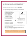
Receive Antenna Phasing Controller DXE-NCC-1 DXE-NCC-1-INS Rev 6 © DX Engineering 2012 P.O. Box 1491 ∙ Akron, OH 44309-1491 Phone: (800) 777-0703 ∙ Tech Support and International: (330) 572-3200 Fax: (330) 572-3279 ∙ E-mail: [email protected] -1- Table of Contents Introduction Features Receiving Antennas Antenna Polarization Antenna Feedlines Antenna Sensitivity Antenna Bandwidth Combining Antennas to Improve Signal-to-Noise Ratio Use with Beverage or Other Low Noise Antennas Phased Verticals & Beverage Systems Noise Reducing Noise and Interference Understanding Noise Removing Noise Front Panel Controls and Switches Rear Panel Connections Internal Jumpers HD1 & HD2 - Antenna Power Enable/Disable HD4 - Antenna Power Source HD5 - TX Muting Installation Connections NCC-1 Dimensions Typical Connections to a Transceiver Phase Nulling with a Transmit Antenna Using two Active Receive Antennas and the RTR-1 One Active Receive Antenna, RTR-1 and Transmit Antenna Operation Using the NCC-1 Technical Description Specifications Appendix A NCC-1 Connection Diagram for High Power Operation NCC-1 Connection Connections for Remotely Powered Receive Antennas Optional Items Technical Support -2- 3 4 5 5 5 5 5 6 7 8 10 10 10 11 12 13 14 15 15 15 16 16 17 18 19 21 22 23 24 25 26 26 27 28 29 32 Introduction The DX Engineering NCC-1 Receive Antenna Variable Phasing Controller is a two-channel receive antenna phasing system. This sophisticated controller allows the user to combine and independently adjust the phase and level of two antenna inputs, essentially creating a fully adjustable phased array out of two similar receive antennas. It can be used with existing or new receiving antenna systems to improve or enhance desired signals by adding desired signals. It can also eliminate or greatly reduce unwanted signals or noise by phase nulling the unwanted signal regardless of the signal or noise type. The NCC-1 is fully compatible with the DX Engineering Active Receive Antennas. Using 102" whips as antenna elements, these antennas can provide excellent receiving performance from 100 kHz to 30 MHz. Two ARAV3-1P active receive vertical antennas can be phased to form a vertically polarized array. The minimum useable spacing varies with local noise floor, but is typically 1/10-wavelength. Maximum spacing for true unidirectional patterns is just over 1/4wavelength, although wider spacing is still very useable. Two ARAH2-1P active receive horizontal antennas can be configured as horizontally polarized dipoles to form a two element horizontally polarized receiving array. The NCC-1 front panel controls provide repeatable directional pattern adjustments. Properly spaced Active Receive antennas are useable over a wide range of frequencies, offering the best possible phase nulling and peaking. The NCC-1 can be used with many other combinations of receiving antennas including Single and Reversible Beverages, Receive Four-Square Arrays, K9AY Loops, and more. It will increase the directivity of any properly spaced combination of two similar antennas. The NCC-1 is primarily designed for 500 kHz to 15 MHz use, although the useful operating range extends from below 300 kHz to above 30 MHz. Typical applications include: Combining two similar non-directional antenna elements to create a directional pattern. Combining two similar directional antennas to produce a better pattern. Reducing overload or interference by removing or reducing a strong signal or noise Reducing interference from distant signals or noise Direction finding -3- Features Phase adjustable through at least 360 degrees in the primary design area (500 kHz to 15 MHz) Exceptional dynamic range - able to handle strong signals without overloading Low noise floor Provisions for optional internal high pass and band pass filters DC controls with smooth repeatable action. Expandable for remote or external control Provides power and transmit muting for external active antennas Antenna and Receive Outputs use RCA phono and Type F connectors to help prevent accidental connection to live transmit feedlines The NCC-1 has four main advantages over typical phased antenna systems: The array can be electrically "steered" or directed using physically stationary antennas The user can adjust direction and wave angle of either a null or peak The response can change from a signal null to a perfect signal peak with a flip of a single switch Front panel adjustments compensate for less-than-ideal installations, making a directional array possible in most situations NOTE: The NCC-1 is a Receive-Only phasing system. It is designed to go between the receiver input port of a radio or transceiver and two receiving antennas. Do NOT transmit through the NCC-1 If transmitted energy is ever allowed to reach the antenna or receive output ports of the NCC-1, serious damage may result in a burned out unit. If this occurs either by intermittent misuse, neglect, or accident, any warranty would be voided and your NCC-1 may not be repairable. Operation of the NCC-1 with Active Receive Antennas in close proximity to transmit antennas (1/10wavelength minimum) and high power operation with a linear amplifier requires additional optional equipment. See Appendix A for details. The NCC-1 is not a Digital Signal Processor (DSP) unit and it is not a Noise Blanker. The NCC-1 is a receive signal RF phasing controller with exceptionally low noise, high dynamic range, level control and phasing range. -4- Receiving Antennas The performance of the NCC-1 is largely dependent on the receiving antennas and their installation. Please carefully read this section and make adjustments or changes to your antennas before using the NCC-1. The NCC-1 will function with almost any combination of antennas but it works best when INPUT A and B antennas have reasonably similar directional patterns. Optimum antenna spacing will vary with the frequency band and what you are trying to accomplish. There are two general rules for antenna spacing: If antennas are too close together (less than 1/10-wavelength), a very stable deep null can be produced but the system will lose gain or sensitivity. If the antennas are too far apart (generally more than 1-wavelength) the nulls and peaks in the pattern will become so sharp it might become impossible to maintain nulls or peaks on sky wave signals. With very wide spacing, signals will fade in and out more rapidly with ionospheric changes. Antenna Polarization It is generally not a good idea to mix polarization of antennas. Although this scheme can work when nulling a groundwave signal or noise, mixing polarizations generally makes nulls or peaks more difficult to find and maintain. When receiving skywave propagated signals, mixing a horizontal antenna with a vertical antenna almost always increases fading. Antenna Feedlines It is not necessary to use any special length of feedline with antennas used in this system or for antennas to be "resonant" or physically large. The front panel controls will compensate for feedline lengths. You should still use a good feedline and make good connections. DX Engineering recommends DXE-F6 75 Ω CATV style cable with weather-tight connectors such as DXE-SNS6 Snap-N-Seal, both available from DX Engineering. Antenna Sensitivity Receiving antennas should not have excessive signal level or gain. They only need enough gain or signal level to have very weak signals limited by external noise. Too much signal level from antennas is actually not good. Normally we should just hear a slight increase in noise (or weak signal) from no antenna connected to having one connected. We would then clearly hear a noise floor increase. For best weak signal reception, background noise of antennas should be around 5 dB, or about 1 S-Unit, above the NCC-1 noise floor. The NCC-1 is a very good match for DX Engineering Active Antenna arrays and closely matches their dynamic range. Higher noise floor antennas can be also be successfully used due to the built-in front panel adjustable attenuators. Antenna Bandwidth Wider bandwidth antennas produce the most stable and reliable performance. Very narrow bandwidth antennas do not work as well. A small resonant loop will be very narrow in response and -5- will shift phase rapidly with frequency changes. This means temperature changes and frequency changes will both require more frequent readjustment of the NCC-1 controls. (Exceptionally wide spaced antennas also produce a similar effect, as will mixing of antenna polarizations in one system.) Combining Antennas to Improve Signal-to-Noise Ratio If your location is limited by noise coming from many directions, you can still use the NCC-1 to enhance signals. The following guidelines apply when enhancing signals: Both antennas must hear the desired signal with similar signal-to-noise ratios. Don’t combine an antenna that hears the signal with one that can’t hear it at all. Adding desired signals from a "quiet antenna" to a "noisy antenna" only makes the quiet antenna noisy. The most reliable and consistent performance occurs with antenna spacing less than 1/4-wavelength when antennas are in line with the desired direction, and less than 1-1/2wavelengths apart when antennas are spaced at right angles to desired directions. Best sensitivity occurs when antennas are more than 1/10-wavelength apart when the antennas are in line with the desired direction, and more than 1/2-wave apart when broadside to the desired direction When enhancing desired signals, it is preferable to locate both A and B INPUT antennas as far from local noise sources as possible. Using a vertically polarized antenna in combination with a horizontally polarized antenna almost always increases fading over an ionospheric path. Note: In cases where one antenna is significantly noisier than the other, it is often possible to use the quieter antenna for the signal and cancel noise with the noisy antenna. The same noise must appear on both antennas. -6- The NCC-1 generally works best when both antennas have similar patterns, polarization, and S/N ratios. You may have to experiment to find the best antenna, but successful operation occurs more often with similar antennas. Use with Beverage or Other Low Noise Antennas The NCC-1 is probably most useful when used to enhance reception on lower frequencies. The NCC-1 is often useful even if the station already employs low noise directional receiving arrays. A suggested method follows: Connect one Beverage or other similar low noise receiving antenna to INPUT A Connect another Beverage or another low noise receiving array to INPUT B Connect the NCC-1 RECEIVER connector to the receiver's input line. If you are using a Reversible Beverage, run two feedlines back to the NCC-1 INPUT connections. Then use the NCC-1 to control the directivity and nulls. A Reversible Beverage system, like the DX Engineering DXE-RBS-1, is ideal to use when both feedlines are run to the NCC-1. It can reduce interference, strong signals or noise from one direction, while peaking reception in the other, improving the Signal-to-Noise Ratio in the desired direction. -7- Phased Verticals & Beverage Systems This unit is an adjustable phasing network that combines two antenna input ports. Antennas can be combined to change or improve directional patterns. Pattern changes can be used to improve signalto-noise ratio even in the absence of strong noise. It is possible to combine almost any type of receiving antennas into a large array. For example: Two verticals or dipoles can be combined to produce a steerable array capable of peaking or nulling signals. -8- Two parallel Beverage antennas spaced an eighth to quarter wave apart with an eighth to quarter wave stagger in the desired direction can be combined to improve front-to-back ratio or steer nulls to the direction of unwanted signals or noise. The best system is often found by planning, although it is often worth experimenting. Using this type of directional phased antenna array you may record phase settings to null stations from known directions. It is then possible to make a direction chart. With optimal antenna spacing it is possible to tell direction within several degrees. -9- Noise Reducing Noise and Interference Unlike conventional noise blankers, the NCC-1 is designed to reduce noise or interference before it gets to the receiver. The NCC-1 can be effective on all types of noise, including interference (QRM) from unwanted signals. The NCC-1 allows the user to continuously adjust both phase and amplitude when combining two antenna inputs. The signal output to the receiver is the addition or subtraction of signals from two separate antennas. Unwanted directional noise can be removed or unwanted signals can be cancelled. Desired signals can be peaked or enhanced. Unlike conventional noise blankers, the phasing method of signal enhancement or rejection has several advantages. Interference much stronger than a desired signal can be completely removed without affecting the signal. The NCC-1 can be effective with all types of interference and all modes. Signals can be peaked instead of nulled with a flip of a switch. Note: Failure to follow guidelines outlined in sections below will often result in reduced nulls or reduced enhancement of distant signals Understanding Noise Noise limits our ability to hear a weak signal on the lower bands. Noise is often an accumulation of many unwanted signals. Noise from antennas is generally a mixture of local ground wave and ionosphere propagated noise sources, although many locations suffer with dominant local noise sources. Noise is generated by randomly polarized sources. Noise polarization is filtered depending on the method of propagation: Noise arriving via the ionosphere is randomly polarized. Noise arrives at whatever polarization the ionosphere favors at the moment. Noise has the same ratio of electric to magnetic fields as a "good" signal. Sources within a few wavelengths of the antenna arrive randomly polarized. The noise does not have a dominant polarization and it can either be electric or magnetic field dominant. Local noise can also be random or directional in nature. Every effort must be made to locate sources of noise that could be eliminated at the source. Dimmer switches, electric timers, security lights, and many other items can be sources of unwanted noise. Plasma televisions are becoming more popular and are a known generator of unwanted noise interference. - 10 - Ground wave noises arriving from a significant distance are vertically polarized. The path along the earth "filters out" and removes any horizontally polarized signals. Horizontal electric field components are "short circuited" by the conductive earth as they propagate and are eliminated. With the exception of ground wave-propagated noise, receiving antenna polarization effects are not predictable. It is possible vertically polarized antennas may be quieter than horizontally polarized antennas. The opposite is also true. It may be difficult to remove noise with any device when: Noise and desired signals come from the same direction and elevation angle Both antennas don’t hear the same noise The noise source is moving around, or noise sources are coming from several directions at the same time Removing Noise The NCC-1 generally works best when both antennas have similar patterns, polarization, and Signal-to-Noise ratios. For the most effective nulling of noise, the antennas on both the A and B inputs must hear the same unwanted noise and should have similar polarization. You may have to experiment to find the best antenna, but successful operation more commonly occurs with similar antennas. Removal of distant interference: Close element spacing is more desirable. Close spacing produces a single null that is wider and more stable. Spacing of 1/4-wavelength or less is most desirable when nulling distant interference or peaking distant signals. Spacing larger than 1/4wavelength can, at your operating frequency, cause multiple nulls in the patterns. Removal of a local noise source: Best performance occurs when the noise (B INPUT) antenna "hears" the noise much louder than it hears desired signals. We want the noise antenna to pick up the largest amount of noise possible, so it should be located as close to the noise source as possible. In this case the polarization is unimportant; whatever polarization hears the noise best. The spacing between antennas can be any convenient distance within one wavelength. - 11 - Front Panel Controls and Switches POWER: Turns power off and on. When powered-off, INPUT B is disconnected and INPUT A is connected directly to the receiver, removing antenna power. Two Attenuator switches reduce gain in ten dB steps. The steps are 0, -10, -20, and –30 dB. The left switch sets INPUT “A” attenuation (primary antenna), the right switch sets INPUT “B” (secondary antenna) attenuation. BALANCE: Provides fine adjustment of gain. It is used to balance or equalize signal levels from INPUT A and B. The BALANCE control provides anywhere from zero to 12 dB attenuation on either A or B. This control has the same “feel” and operation as the balance controls on conventional stereo systems. Maximum gain on both channels occurs when the BALANCE control is positioned in the center of the range, and gain is reduced as the knob is rotated away from a particular channel. If you rotate the BALANCE control clockwise, the gain of INPUT A is reduced. Without precise signal or noise level balancing between INPUTS A and B, noise nulling or canceling will not be as deep as possible. PHASE: Changes the phase delay relationship between INPUT A and B. The resulting phase shift will change the position of nulls or directions of peak signal response. INPUTS: Reverses A (primary) and B (secondary) antenna inputs. This is done after attenuation adjustment. Changing this switch is the electrical equivalent of physically swapping antenna element locations. BAND: Optimizes phase range and selects the filter boards used. "L" is for frequencies below 10 MHz, and selects optional filters FL1 & FL3. "H" is for frequencies above 5 MHz and selects optional filters FL2 & FL4. B PHASE: Moves B INPUT phase by exactly 180 degrees. NORM is 180 Degrees or no phase reverse, REV is 0 Degrees. - 12 - Rear Panel Connections INPUT A: Primary Receive Antenna – Phono and F style connector. Phono and F style connectors are used to prevent accidental connections to transmitting equipment. INPUT B: Secondary Receive Antenna – Phono and F style connector. Phono and F style connectors are used to prevent accidental connections to transmitting equipment. The NCC-1 can supply T/R Controlled DC power to active antennas through the INPUT A and B coaxial lines. DC power can come from either the NCC-1 supply or through a separate rear panel power connector. The NCC-1 has an internal high-speed solid-state switch that will switch up to 30 Volts DC Positive voltage at 150 mA per input channel for powering receive antennas. (See Appendix A for special instructions for remotely powered receive antenna systems that require 15 to 30 Vdc) RX OUT: Receive Signal output to receiver – Phono and Type F connector. These types of connections work well with most transceiver and receiver RX ANT Inputs. Main Power: The NCC-1 requires well-filtered +13.8 to +15 Vdc @ 1A minimum. The NCC1 should be connected to a well filtered and regulated +13.8 to +15 Vdc @ 2 A power source. A 2.1 mm plug, center positive power plug is included with the NCC-1. External high current and well filtered sources, such as station power supplies, should be appropriately fused at the power source. The use of switching power supplies is discouraged due to the presence of noise in their output. ANT PWR: – 2.1 mm jack. Supplies external voltage to INPUT A and INPUT B feedlines to power active antennas or other devices. Allowable voltage range is +13.8 to +30 Vdc with 300 mA maximum load current, well filtered & fused for both INPUTs combined. A 2.1 mm plug, center positive power plug is proved with the NCC-1. T/R CTRL: – Phono connector. Activated by pulling to ground or by external application of voltage (internal jumper selectable). When activated INPUT A is bypassed directly to receiver and INPUT B disconnects. Activation also removes antenna power from both INPUTs. The T/R CTRL line can be configured to disable the NCC-1 and remove power from antennas attached to the NCC-1 when pulled either low or high. The normal switching threshold voltage - 13 - is +3 Vdc. A valid T/R CTRL input disconnects INPUT B and bypasses INPUT A directly to the RX OUT. Antenna voltage is also removed from input ports when T/R CTRL is activated. This reduces chances of damaging the NCC-1 when the receiving antennas are located close to transmitting antennas and allows the DX Engineering ARAV series active antennas to mute, protecting them from transmitted energy. Internal Jumpers The NCC-1 motherboard has jumpers that configure the antenna jack power and transmitter muting options. With the unit unplugged and no power connected, remove 6 screws on each side of the cover and lift it off. To configure the jumpers, turn the NCC-1 so the components match the orientation of Figure 1. The Default jumper positions as shown: HD1 – Antenna A Power: OFF HD2 – Antenna B Power: OFF HD4 – Antenna Power Source: 13.8V HD5 – TX Mute Polarity: NOR or Low (Most transceivers) Both Jumpers Installed. Figure 1: NCC-1 Jumper Locations The jumpers are small plugs that fit over and connect two of the pins on the associated header. The jumper is removed by pulling straight out and installed by aligning with two pins and pushing straight in to fully seat the jumper. - 14 - HD1 & HD2 - Antenna A and B Power - Activate/Disable Jumpers HD1 and HD2 (both three pin headers) activate or disable power on the feedline to INPUTs A and B. HD1 is in the front corner of the circuit board directly behind the PHASE control and BAND toggle switch. This header controls power to the INPUT A port. When this jumper is on the middle and forward pins, power is OFF to INPUT port A as shown in Figure 1. When this jumper is moved and connects the middle and rearmost pins, power is applied to INPUT port A. HD2 is along the edge of the board directly towards the rear from HD1. This header controls power to INPUT port B. When this jumper is on the middle and forward pins, power is OFF to INPUT port B as shown in Figure 1. When this jumper is moved and connects the middle and rearmost pins, power is ON to INPUT port B. Note: During TX Mute activation, power to the active antennas is disabled regardless of the Antenna Power jumper settings. HD4 - Antenna Power Source The HD4 jumper determines the source of active antenna power, either through the NCC-1 power supply or the ANT PWR jack on the rear panel. HD4 is a three pin header located at the rear of the main circuit board near the power jacks and the two large power transistors that are bolted to the main circuit board. When the jumper on HD4 is positioned on the middle and 12V pins (factory default position), as shown in Figure 1, antenna power comes from the NCC-1 main power supply. When the jumper on HD4 is positioned toward EXT, the antenna port power comes from the ANT PWR jack. Only when an alternative power source is used for active antenna devices powered via feedline connected to INPUT A and B, should the HD4 jumper be set to EXT. HD5 - TX Mute Polarity HD5 controls the logic state that activates the TX Mute polarity function and is located just below the rear panel Ext Control connector. HD5 is a four pin header. When HD5 has two pin jumpers in both positions completely filling the header, operation is normal. A logic low activates the TX Mute. This means any voltage above 3 volts positive or an open circuit allows the NCC-1 to function normally. Power is available for use at antenna ports. Anything below 1 volt positive (including a "Ground on Transmit") causes the NCC-1 to mute. Power is removed from the antenna ports and the INPUT A port is connected directly to the receiver port. Switching time is about 2 ms. - 15 - If one shunt on HD5 is installed on the center two header pins, logic is reversed. Positive voltage over 3 volts applied to the TX Mute will force the NCC-1 into standby and disable the antenna power feature. Any voltage below one volt, including a grounded condition, will allow the unit to function normally. Installation Please read the following section carefully. The best location for this unit is at the operating position with easy access to the controls since you will be using the S-Meter on your receiver while adjusting the NCC-1. Connections Make connections to the NCC-1 as follows: Connect a fused power source of +13.8 to +15 Vdc @ 2A, well filtered & fused to the 2.1 mm center-positive MAIN PWR jack using the included 2.1 mm plug. Well filtered and fused station power is recommended. Connect a receiving antenna to the INPUT A F style or Phono connector. Connect a second receiving antenna (or local noise source antenna) to the INPUT B F style or Phono connector. Connect a standard shielded audio style cable between the T/R Control Phono connector and an external transmit control source. o By default, the NCC-1 is set to mute when the T/R Control line is pulled LOW. This is normal station wiring. Many modern transceivers have a rear panel amplifier control jack typically labeled as "TX", "AMP", "Send”, “Control" or "TX GND" that pulls low when the transceiver is keyed. (Check the user manual for your radio) Note: Internal jumpers (HD5) can be changed to allow the NCC-1 to use an inverted + 5 to +50 Vdc amplifier control line. This is an unusual configuration. o T/R Control line on the NCC-1 can be paralleled on the same control line used for the amplifier provided the amplifier does not load the line when not transmitting. If the amplifier does load the line, you will have to add a blocking diode. o The DX Engineering TVSU-1A programmable sequencer can also be used to provide the proper transmit/receive switching for an amplifier, transceiver, and the NCC-1. Refer to Appendix A for the high power installation connection diagram. - 16 - Connect the RX OUT jack to a receiver or the transceiver receive-only antenna port. Do not connect the RX OUT connector of the NCC-1 to a transceiver RF output! If desired, connect a fused external power source to the ANT PWR 2.1 mm center-positive jack if you are not using the NCC-1 supply to power antennas (HD4 Jumper Selectable). The allowable voltage range is +13.8 to +30 Vdc (well filtered & fused) with 300 mA maximum load current for both INPUTs combined. The DX Engineering DXEARAH2/V3 Active antennas typically require a nominal 13 Vdc @ 50 mA each. See Appendix A for special instructions and a diagram for remotely powered antennas that require +15 to +30 Vdc. - 17 - Typical Connections to a Transceiver Figure 2 shows the normal default connection of the NCC-1 to a typical Transceiver with Receive Input. Antenna Inputs A and B may be connected to any receive antennas as discussed in the Introduction, and in the following pages. Power is supplied to the Active Receive Antennas by setting the NCC-1 internal jumpers according to instructions setting in Figure 2. - 18 - Phase Nulling with a Transmit Antenna As described throughout this manual, the primary advantage of using receiving antennas for phase nulling of unwanted signals is to enhance the signal to noise ratio (S/N) of the desired weak signal. Wherever possible, the use of low signal, low noise receiving antennas will generally produce superior results, especially with the NCC-1. HF and Low Band (160, 80, 40 meters) transmitting antennas usually receive high levels of noise and when used for phasing, the result is a noisy signal. However, there are cases where phasing with a transmit antenna is desired. Some fortunate Amateur Radio Operators reside in locations where the ambient noise levels on their transmit antenna is low enough that their benefits from phase nulling and peaking will be maximized. Many radio enthusiasts live in areas where some type of noise or strong signal interference is preventing normal or weak signal DX receive operations. Some Amateur Radio Operators must use a transmit antenna for nulling out undesired signals because receive only antennas will not 'hear' the desired signal. Many of the low noise advantages of the NCC-1 will be hidden by strong ambient noise if a transmit antenna is used as a receive antenna for the NCC-1. If your transceiver has both Receive Antenna Input (RX IN or RX ANT) and a Receive Output (RX OUT), you may use the transmit antenna receive signals that are available from that port for phasing the transmit antenna against those from a receive antenna. Figure 3 demonstrates the connection scheme for phasing a receive antenna against a transmit antenna. Special adjustments to the attenuator and balance may be required. Additional attenuation of the RX Out to INPUT B may be required in certain conditions, so the signal or noise level coming from the transmit antenna does not override the signal or noise level coming from the receive or noise "sense" antenna. If used, active antenna power may be derived internally from the NCC-1 and is automatically disconnected during transmit by setting jumpers HD1 and HD4 per the chart listed in Figure 3. If a non-powered, passive receive antenna is used, jumpers should be in the default position as supplied. Refer to Figure 1. - 19 - Phase Nulling with a Transmit Antenna and a single Active Receive Antenna - 20 - Figure 4 - DXE-NCC-1 Receive Antenna Variable Phasing Controller with two Active Receive Antennas using high power to the transmit antenna - 21 - Figure 5 - DXE-NCC-1 Receive Antenna Variable Phasing Controller with one Active Receive Antenna - 22 - Operation For two antennas with approximately equal desired signal levels, or for two antennas with approximately equal undesired signals or noise levels. 1. Connect the NCC-1 to your station and a suitable power source. 2. Set the front panel controls as follows: A. Both A and B attenuator switches to the 0 dB position, unless one antenna requires more preset attenuation B. BALANCE control to the center position, the knob indicator line should be centered vertically C. PHASE control rotated to zero position D. INPUTS switch to NORM E. B PHASE NORM-REV switch set to NORM F. BAND switch to L for operation below 5-10 MHz or H for operation above 5-10 MHz. In the range of 5-10 MHz, either setting may work G. POWER On To get the best rejection of unwanted signals or noise, rotate the PHASE control until the noise or interference is at the lowest level. If a null cannot be found, change the PHASE NORM/REV switch to the REV position. The null might be shallow until levels are balanced. Adjust the BALANCE control to further reduce noise or interference. It may be necessary to go back and forth between PHASE and BALANCE controls a few times. If the BALANCE control is not within 90 degrees of the center position, apply attenuation to the opposite channel that the BALANCE pointer is on. This should center the BALANCE control indicator line, or it may reset the balance point to the opposite side of the control if the antenna's signal difference is between 3 to 9 dB. If one antenna is always 3 to 12 dB different than the other, then either the weaker antenna should be improved, or the stronger antenna may be attenuated with a 3 or 6 dB pad to provide a better balance between sources. Without precise signal or noise level balancing between antenna INPUTS A and B or cancelling will not be as deep as possible. Often a little experimentation is required to get the best performance using different selections of available antennas and phase relationships. You can also reverse directions by changing INPUT A and INPUT B using the INPUT switch. This switch is most useful when elements are in line with - 23 - desired or undesired directions, but there are cases where it can extend phase range and aid in achieving a better null. The PHASE NORM-REV switch will turn a NULL point into a PEAK point. Adjust for a null as above, and then reverse the PHASE switch. Unwanted signals or noise can only be nulled if present on both A and B antennas. Desired signals can only be peaked if the have about the same S/N ratio on both antennas and when spacing is correct. Different fading rates and times between dissimilar or wide spaced antenna can make control adjustment tedious. The most stable and reliable nulls occur when antennas are moderately close together (between 1/10 and 1/4-wavelength apart), oriented in the same direction, and sharing the same polarization. Using the NCC-1 The PHASE control changes the phase relationship between A and B INPUTs, effectively changing the direction of a peak or null. When the phase control is fully counterclockwise, INPUT A has minimum phase shift and INPUT B has maximum phase shift. As the PHASE control is rotated clockwise phase shift in INPUT A increases while phase shift in INPUT B decreases. The PHASE NORM-REV switch inserts zero (REV) or 180-degree (NORM) phase inversion in INPUT B. This switch has the effect of changing a peak to a null, or a null to a peak. If a signal is nulled with the NORM-REV switch in one position, changing the position will result in a peak. It is best to know the approximate level from both antennas. If you are using greatly dissimilar antenna levels dial in enough attenuation on the stronger antenna to approximately level signals. If you have a general coverage receiver, select a strong steady signal between 1.5 and 30 MHz. The ideal signal would be ground wave, although the time and frequency standards on 5, 7.335, and 10 MHz are good alternatives. Try to use a signal that does not have excessive or rapid fading. If you know the signals from two antennas are not the same level: A. B. C. D. E. Connect antennas, Balance control in center, Set both attenuators on 0 dB. Tune in a strong clear station Dial 30 dB of attenuation in on INPUT B. The S meter reading is the level from A. Note this level. Before the signal has a chance to fade, remove attenuation from B (set to zero dB) and put 30 dB of attenuation on INPUT A. F. Note level. This is the level from B. G. The higher the S meter reading, more attenuation will be required. One S unit is typically around 5 dB, although that number can range from 1-8 dB depending on the receiver and the exact signal level. Set attenuators so the HIGHEST signal level port has the MOST attenuation. - 24 - H. Adjust phase control for a null or minimum signal. I. Adjust the balance for lowest reading J. Change PHASE NORM-INV to opposite position. The signal should now be strong. Note: Any signal being nulled or peaked must be adjusted to the same level as seen at the receiver from both channels or the NCC-1 Phase Control will not work as expected. Technical Description Voltages for phase adjustment are linearized through an active feedback system. Phase adjustment is spread over a wide linear control range. This gives the phase control a smooth feel and improves the ability to manually reset it. The NCC-1 uses two exceptionally flat-response phasing bridge systems and a unique system of mirrored bridges in each channel. When phase delay is increased in one channel, phase delay is simultaneously decreased in the other channel. Any level changes while adjusting phase are automatically compensated in the other channel. There is virtually no channel balance error over the entire range of the phase control. The NCC-1 has a dynamic range up to 30 dB (1000 times) better than other popular noise canceling systems. It also has provisions for further improvements in exceptionally strong signal environments. The NCC-1 has four filter slots for optional high pass and band-pass filters. Filters remove undesired signals before reaching any active devices, greatly increasing dynamic range in extreme RF environments. Note: Effective and proper operation occurs only when the same noise (for nulling noise) or the same desired signal (for signal enhancement) is present on both A and B INPUTs. - 25 - Specifications Useable Frequency Range: 300 kHz to 30 MHz The NCC-1 is primarily designed for 500 kHz to 15 MHz use, although useful operating range extends from below 300 kHz to above 30 MHz. Third Order Output Intercept: +32 dBm each Input, +38 dBm both inputs combined Gain Flatness: +/- 1 dB Over Complete Phase Rotation Gain: Adjustable from 0 dB to –40 dB Available Phase Rotation: >360 degrees between 500 kHz and 15 MHz Power : NCC-1 +13.8 Vdc nominal @ 2A, well filtered & fused Antenna Port power: +10 to +30 Vdc @ 300 mA maximum, TX muting available Appendix A Every radio manufacturer's accessory interconnection scheme is different. The following are only suggestions, and you should consult your radio manufacturer's manual for details and requirements for receive signal inputs/outputs and switching voltages. NCC-1 Connection Diagram for High Power Operation Using the NCC-1 with DX Engineering Active Receive Antennas, close spaced, and a high power transmit amplifier. When high power operation is desired, Figure A1 shows the correct method of protecting DX Engineering Active Receive Antennas from transmit energy using the optional DXE-TVSU-1A Time Variable Sequence Unit. The optional TVSU-1A is required for high power operation to control the timing of the transceiver, amplifier, NCC-1 and the Active Receive Antennas. PTT using a hand switch or foot switch is required. VOX operation on the transceiver may not be used. CW keying is connected directly to the TVSU-1A, not the transceiver. The TVSU-1A provides side tone in real time to prevent confusion of the delayed CW keying. Side tone from the radio needs to be turned off. The optional DXE-DCPC-24 is specifically used in a DX Engineering receiving antenna phasing system between the "PRE-AMP POWER OUT" port on the DXE-TVSU-1A Time Variable Sequence Unit, and the "ANT PWR" power input on the DXE-NCC-1 Receive Antenna Phasing Controller. The DXE-DCPC-24 is a 24 inch red and black stripe power cable that features TWO 2.1 mm DC power connectors known as "barrel", "concentric" or "tip" connectors, one at each end. This special cable is used in applications where DC power is supplied from one device to another. - 26 - - 27 - NCC-1 Connections for Remotely Powered Receive Antennas If your special receive antenna system requires any voltage, even those greater than +13.8 Vdc nominal, then the NCC-1 default internal jumper setting for HD4 is set to EXT. Refer to Figure A-2. This will allow up to +30 Vdc @ 150 mA maximum per antenna input channel (300 mA combined maximum). Your alternative fused power source of up to 30 Vdc would be connected to the ANT PWR jack on the rear of the NCC-1. TX mute connection to the T/R CTRL will interrupt this power feed. If relays or pre-amplifiers are used remotely, their switching time for a receive / transmit /receive sequence must be faster than the transceiver. The DXE-RPA-1 Receive Pre-Amplifier was not designed for remote operation of a keyed power source. Minimal losses on low band receiving feedlines normally allow for proper location of the RPA-1 on the receiver input or the transceiver RX Ant Input. - 28 - Optional Items DXE-ARAV3-1P - Active Receive Antennas w/ Internal Disconnect Relay DX Engineering’s Active Receive Antenna Systems offer excellent receiving performance from 100 kHz to 30 MHz using a whip antenna element 102 in. long. DX Engineering’s unique design makes it vastly superior to traditional active antennas in both strong signal handling and feedline decoupling. You get significantly better weak signal reception due to lower spurious signal interference and reduced noise. This antenna system is ideal for Amateur Radio or Shortwave Listening. The ARAV3-1P active antennas ground the antenna element when power is turned off. These models are used in installations when spacing from transmit antennas is less than 1/2 wavelength but more than 1/10 wavelength (on the lowest frequency). The units should be used with a sequencer like our TVSU-1A or other reliable means to ensure the units are powered off before any RF appears. Four of these can be used to build a high performance Receive Four-Square System using our Receive Four Square Controller. Features Close Spacing from Transmit Antennas – element grounded at power-off Sensitive − weak signal sensitivity rivaling full size antennas Wide Bandwidth – 100 kHz to 30 MHz Excellent Strong Signal Handling − outstanding Third Order Intercept of +30 dBm Reduced Noise − quiet FET followers and exceptional feedline shield isolation Long Life − high quality stainless and brass mounting hardware, metal enclosure Compact − stainless steel tapered element has low visual and environmental impact Easy Mounting and Installation Flexibility − pre-drilled mounting plate and universal V-saddle clamps DXE-RPA-1 - Receiver Preamplifier, 0.3-35 MHz This is the best HF low noise amplifier available. The RPA-1 is optimized for 0.3-35 MHz operating range. The pushpull amplifier design and robust components enable it to withstand high signal levels and operate when you need it most. The dynamic range of the RPA-1 is better than most receivers. The RPA-1 is suitable for indoor or outdoor installation, with the option of being powered through the coaxial feed. The metal housing provides shielding and improved lifespan. The unit uses RCA type phono jack and CATV F connector for the input and output connections, and has a relay that automatically bypasses the amplifier when dc power is removed. Benefits: Push-pull operation eliminates harmonic distortion High quiescent current increases ability to handle strong signals without distortion or overload Meticulous craftsmanship and durable components provide superior dynamic range RCA type phono jack and type F connector ease installation Simplified switching - automatic bypass eliminates gain when dc power is off +13.8 to +18 Vdc power using power connector or through the coax +13.8 to +18 Vdc through coax enables remote operation at antenna - 29 - DXE-RTR-1 - Receive Antenna Interface for Transceivers Now you can add a dedicated receive antenna to HF transceivers which lack a separate RX antenna input port! The DXE-RTR-1 Receive Antenna Interface (patent pending) is a unique multi-purpose switch unit which automatically or manually switches the RF output antenna connector on any HF transceiver between a separate receiving antenna system and a standard transmitting antenna. The switching is fast enough - about 4 ms. - to allow QSK CW operation. In its simplest application, it allows you to add a receiving preamp to improve reception of those really weak ones! The DXE-RTR-1 enables operators to enjoy the improved reception that a low noise receiving antenna system offers. Connection to a Beverage, Receive Four-Square, Active Receive Antenna, and other receiving antennas and accessories is now possible, safely, only with the DXE-RTR-1. Requires +13.8 Vdc well filtered @ 2A for operation. Attractive Heavy Stainless Steel Enclosure 200 Watt Switching Capability Supports CW full break in Main Antenna has SO-239 connector Receive Outputs use RCA phono and Type F connectors Safe switching - transmit antenna is always connected to transceiver on power-off Hot switching lockout - disables receive antenna during transmit mode Versatile - allows inclusion of RF Preamps and other RX accessories DXE-F6 - 75 ohm F-6 Style, Direct Bury Coaxial Cable: Full Spool or Custom Cable Assemblies DX Engineering recommends using a high quality 75 Ω “flooded” F6 type coaxial cable. Flooded style cables have the distinct advantage of automatically sealing small accidental cuts or lacerations of the jacket. Flooding also prevents shield contamination and can be direct-buried. This low-loss cable features dual shields and an 85% Velocity Factor. Custom cable assemblies available, Call DX Engineering for details. DXE-SNS6 Snap-N-Seal connectors are recommended for use with this coaxial cable to ensure a high quality and weather resistant feedline connection. The proper tool DXE-SNS-CT1 must be used to install these connectors. DXE-CPT-659 - Coax Cable Stripper for CATV F-6, RG-6 and RG-59 coaxial cable Coax Cable Stripper for CATV F-6, RG-6 and RG-59 coaxial cable. Includes 1 Replacement Blade - DXE-CPT-659 Prepares CATV F-6, RG-6 and RG-59 coaxial cable for the installation of an "F" type connector - Onestep cutting motion Precision cut No nicks or scratches to conductor DXE-SNS6-25 - Watertight Coaxial Connector, Snap-N-Seal for CATV F-6 Cable, 25 pieces Snap-N-Seal is an environmentally sealed CATV F coaxial connector system for harsh environments. The connectors have a unique, 360 degree radial compression system that offers the signal leakage protection required for high performance receive systems. Quad sealed system prevents moisture from migrating into the connection 360 degree radial compression provides superior RF integrity (-95 dB typical, 60% bonded foil cable) Easy cable preparation Connector to cable retention of 40 lbs minimum Superb impedance match to 1 GHz Manufactured of high quality 360 brass, cadmium plated with yellow chromate coating for maximum corrosion resistance UV-resistant plastic and O-rings provide a reliable environmentally sealed connector - 30 - DXE-SNS-CT1 - Compression Tool for Snap-N-Seal 75 ohm Coaxial Connectors Ratchet compression tool for installing DXE-SNS6 Snap-N-Seal coaxial connectors. Ordinary pliers will not install these connectors properly. DXE-TVSU-1A - Time Variable Sequencer Unit The DX Engineering TVSU-1A Time Variable Sequencer Unit is a microprocessor-based transmit / receive controlsignal delay unit. It provides 0-30 ms of delay, programmable in 2 ms increments, to as many as five outputs tied to the CW keying or push-to-talk (PTT) lines. By controlling the receive-to-transmit (and back) timing of linear amplifiers, preamplifiers, and other sensitive equipment, damage caused by improper switching can be eliminated. This sequencer improves CW performance by eliminating annoying leading edge chopping or truncating of Morse characters. This is especially important in contests or pileups where sending accuracy is critical. The TVSU-1A can also control external devices such as preamps, active antennas, or external relays that need to have power removed during transmit. Separate power-in and power-out jacks on the front panel are used to control external power in this type of application. Two 2.1 mm power plugs and two 3.5 mm stereo plugs are provided. Benefits Control timing of PTT turn-on, hang delay of PTT, amplifier hang delay, external antenna relay hang delay and turn-on delay of auxiliary output Dip switch settable delays of 0-30 milliseconds in 2 millisecond steps Side tone generator that follows input of keyer or hand key not transmitter Side tone pitch can be programmed from 300 to 1000 Hz in 50 Hz steps, front panel headphone jack with adjustable volume Supports CW full break in Can control external power to our Active Receive Antennas and permit operation in closer proximity to transmit antennas DXE-DCPC-24 DC Power Cable, 2.1 mm plug both ends The DXE-DCPC-24 is a 24 inch red and black stripe power cable that features TWO 2.1 mm DC power connectors known as "barrel", "concentric" or "tip" connectors, one at each end. This unusual patch cable may be used for interconnecting devices, one of which offers a power output 2.1 mm jack, and the other requiring a nominal DC voltage input to a 2.1 mm jack. Length: 24 inches (61 cm) from connector to connector Connectors: 2.1 mm power barrel plugs (aka concentric or pin plugs) Wire: Red and Black stripe zip cord (small) Rating: Nominal 2 A @ 13.8 Vdc This special cable is used in applications where DC power is supplied from one device to another. The DXE-DCPC-24 is specifically used in a DX Engineering receiving antenna phasing system between the "PREAMP POWER OUT" port on the DXE-TVSU-1A Time Variable Sequence Unit, and the "ANT PWR" power input on the DXE-NCC-1 Receive Antenna Phasing Controller. - 31 - Technical Support If you have questions about this product, or if you experience difficulties during the installation, contact DX Engineering at (330) 572-3200. You can also e-mail us at: [email protected] For best service, please take a few minutes to review this manual before you call. Warranty All products manufactured by DX Engineering are warranted to be free from defects in material and workmanship for a period of one (1) year from date of shipment. DX Engineering’s sole obligation under these warranties shall be to issue credit, repair or replace any item or part thereof which is proved to be other than as warranted; no allowance shall be made for any labor charges of Buyer for replacement of parts, adjustment or repairs, or any other work, unless such charges are authorized in advance by DX Engineering. If DX Engineering’s products are claimed to be defective in material or workmanship, DX Engineering shall, upon prompt notice thereof, issue shipping instructions for return to DX Engineering (transportation-charges prepaid by Buyer). Every such claim for breach of these warranties shall be deemed to be waived by Buyer unless made in writing. The above warranties shall not extend to any products or parts thereof which have been subjected to any misuse or neglect, damaged by accident, rendered defective by reason of improper installation, damaged from severe weather including floods, or abnormal environmental conditions such as prolonged exposure to corrosives or power surges, or by the performance of repairs or alterations outside of our plant, and shall not apply to any goods or parts thereof furnished by Buyer or acquired from others at Buyer’s specifications. In addition, DX Engineering’s warranties do not extend to other equipment and parts manufactured by others except to the extent of the original manufacturer’s warranty to DX Engineering. The obligations under the foregoing warranties are limited to the precise terms thereof. These warranties provide exclusive remedies, expressly in lieu of all other remedies including claims for special or consequential damages. SELLER NEITHER MAKES NOR ASSUMES ANY OTHER WARRANTY WHATSOEVER, WHETHER EXPRESS, STATUTORY, OR IMPLIED, INCLUDING WARRANTIES OF MERCHANTABILITY AND FITNESS, AND NO PERSON IS AUTHORIZED TO ASSUME FOR DX ENGINEERING ANY OBLIGATION OR LIABILITY NOT STRICTLY IN ACCORDANCE WITH THE FOREGOING. ©DX Engineering 2012 DX Engineering®, DXE®, DX Engineering, Inc.®, Hot Rodz®, Maxi-Core®, DX Engineering THUNDERBOLT™, DX Engineering Yagi Mechanical®, EZ-BUILD®, TELREX® and Gorilla Grip® Stainless Steel Boom Clamps, are trademarks of PDS Electronics, Inc. No license to use or reproduce any of these trademarks or other trademarks is given or implied. All other brands and product names are the trademarks of their respective owners. Specifications subject to change without notice. - 32 -