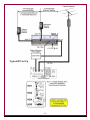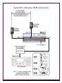
1
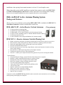
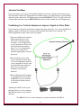
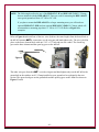
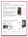
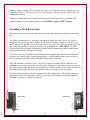
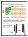
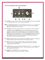
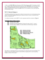
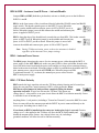
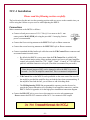
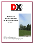
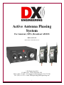
Active Antenna Phasing System For Amateur, SWL, Broadcast AM DX DXE-AAPS3-1P DXE-AAPS3-1P-INS-Revision 0a © DX Engineering 2012 P.O. Box 1491 ∙ Akron, OH 44309-1491 Phone: (800) 777-0703 ∙ Tech Support and International: (330) 572-3200 Fax: (330) 572-3279 ∙ E-mail: [email protected] -1- Table of Contents Introduction System Package and Features DXE-ARAV3-2P - Active Receive Vertical Antennas DXE-NCC-1 - Receive Antenna Variable Phasing Unit Additional Items Needed, But Not Supplied Technical Description Active Vertical Antennas Antenna Feedlines Combining two Vertical Antennas to improve S/N Ratio Noise Nulling Interference and Noise Understanding Noise Basic Tools Required Active Vertical Antenna Installation Location Assembly Ground Mounting Rod Providing a Good RF Ground Connections Coaxial Cable Feedline ARAV2 Low Frequency Response - Internal Jumpers Alternate Mounting NCC-1 NCC-1 Front Panel Controls and Switches NCC-1 Rear Panel Connections NCC-1 Internal Jumpers NCC-1 Installation Connections Radio Interface Diagrams Operating the Receive Phasing System Manual Updates Optional Items Technical Support Warranty -2- 3 4 4 4 5 5 6 6 7 7 7 8 8 8 9 11 12 13 13 13 14 15 16 17 19 19 20 24 25 26 28 28 Introduction Phase nulling with two antennas and a phasing unit allows an operator to hear a desired signal by reducing or completely removing a much stronger interfering signal arriving from a different direction, without affecting the desired signal. Ideal for Amateur Radio, Shortwave Listening or Broadcast AM DX reception, the DXE-AAPS3-1P Active Antenna Phasing System (AAPS) offers excellent directional receiving performance from 500 kHz to 15 MHz using two high quality DXE-ARAV3 vertical receive antennas working in conjunction with the outstanding DXE-NCC-1 Receive Antenna Variable Phasing Unit. DX Engineering’s unique design is vastly superior to traditional active antennas in both strong signal handling and feedline decoupling, providing significantly better weak signal reception due to lower spurious signal interference and reduced noise. Coupled with the DXE-NCC-1 Receive Antenna Variable Phasing Unit, this package makes up a complete electronically rotatable receive antenna system. THIS IS A RECEIVE-ONLY SYSTEM You should never attempt to transmit through the system. The use of bypass relays and sequential timing is required to avoid damage to the active receive antenna system. Placing the active receive system on the same mast or tower as the transmit antenna is not recommended. This compact receiving antenna system operates over a very wide bandwidth with superior strong signal performance. The output Third Order Intercept (TOI) is approximately +30 dBm. This is significantly better than most aftermarket preamplifiers and receivers - making it one of the cleanest active antennas on the market, reducing or eliminating spurious signals. Feedline decoupling, absent in some other popular designs, is also exceptionally good. Decoupling the shield greatly reduces feedline conducted noise and unwanted signal interference Any receive system can be affected by local noise sources. Local noise can be random or directional in nature. First, every effort must be made to locate sources of noise that could be eliminated at the source. Dimmer switches, electric timers, photocell-operated security lights, and many other items can be sources of unwanted noise. Plasma-screen television receivers are becoming more popular and are a known generator of unwanted noise interference. When the noise source is directional in nature, using the two DXE-ARAV3 receive antennas in conjunction with the DXE-NCC-1 allows the user to phase out the noise being received. Ideally your receive antennas should be a minimum of 1/2-wavelength away from any transmit antenna (on the lowest frequency) to avoid mutual coupling and the transfer of any noise being passively re-radiated by the transmit antenna. The DXE-ARAV3 series active vertical antenna system also grounds the receive antenna element when power is turned off for protection of the active devices. The DXE-ARAV3 active receive antennas, used in the DXE-AAPS3 package, may be used in -3- installations when spacing from transmit antennas is at least 1/10-wavelength or more. When using radio systems and RF amplifiers an optional time sequencer such as the DXE-TVSU1A Time Variable Sequencer Unit should be used to ensure the correct timing while switching from receive to transmit, and back to receive to protect the active receive antennas. DXE-AAPS3-1P Active Antenna Phasing System Package and Features The two active receive antennas system package DXE-ARAV3-2P is combined with DXE-NCC-1 Noise/Phase Controller to make a steerable dual vertical array. DXE-ARAV3-2P - Active Receive Vertical Antennas (Two antennas) (2) Non-conductive mounting plates (2) Solid brass element mounting blocks (2) High quality, 102 in. tapered stainless steel whip antenna elements (2) AVA-2 Active matching systems w/ Internal Antenna Disconnect Relays (2) Element connection wires (2) Sets of Stainless steel clamps and hardware for element assembly DXE-NCC-1 - Receive Antenna Variable Phasing Unit Reduce overload or interference by nulling a strong signal or noise before it gets to your receiver Better and more stable nulling than any other noise canceller or phasing unit on the market Peak weak signals hidden under a strong signal on the same frequency Null out local AM broadcast stations Null out noise from power line arcing, lamp dimmers, motors and consumer electronics arriving from a single direction Best alternative to DX Engineering's Receive Four-Square antenna Combine two antennas to create a directional pattern The NCC-1 enables you to adjust the antenna array pattern as if you were moving the antennas Special Features Exceptional Dynamic Range, nearly 1000 times better than nearest competitor Phasing is voltage controlled allowing precise resetting of phase Phasing rotates more than 360 degrees with smooth control Built-in two channel voltage controlled attenuator system Low noise, high dynamic range amplifiers Vastly superior dual channel complementary phasing system Very low noise floor Separate controls for reversing channel and phase Works on all modes, 300 kHz to 30 MHz Provides power for external active antennas Input for mute on transmit A sequencer such as the DXE-TVSU-1A should be used to ensure the correct transmit to receive switching when operating with a high power amplifier. -4- Additional Items Needed, But Not Supplied Mounting pipe and/or copper or copper clad ground rod, 1/2" to 3/4" OD, 4 ft. long (included clamps work with ground rods from 1/2 in. to 3/4 in.) DXE-F6-CTL - 75 Ω F-6 Style, Direct Bury Coaxial Cable: Full Spool or Custom Cable Assemblies. Flooded coaxial cable is recommended. CATV F-6 is a high quality 75 Ω flooded coaxial cable. Flooded coaxial cables automatically seal small accidental cuts or lacerations of the cable jacket. Flooded cables also prevent shield contamination and can be direct-buried. Contact DX Engineering to have custom lengths of CATV F-6 cable manufactured with DXE-SNS6 - Snap-NSeal 75 Ω Coaxial Connectors installed. DXE-CPT-659 - Coax Cable Stripper for CATV F-6, RG-6 and RG-59 coaxial cable. DX Engineering’s economical stripping tool prepares CATV F-6 style coax for connectors in one operation and includes an extra cutting cartridge. DXE-SNS6-25 - Watertight Coaxial Connector, Snap-N-Seal for CATV F-6 Cable, 25 pieces The feedline shield is used as the ground return for the active antenna power, so the feedline connections must be high quality and weather resistant. For this reason, it is recommended using Snap-N-Seal type F connectors DXE-SNS6-25. DXE-SNS-CT1 - Compression Tool for Snap-N-Seal 75 Ω Coaxial Connectors. The DXESNS6-25 connectors cannot be installed with normal crimping tools or pliers. An installation tool such as the DXE-SNS-CT1 is essential for proper connector installation. UMI-82180 - DX Engineering Approved RTV Sealant. Permatex Black RTV Sealant, NonAcetic. Avoid using any corrosive sealant which has a vinegar-like smell. UMI-81343 - Anti-Seize should be used on stainless steel hardware (small amount on threads) to prevent galling and to ensure proper torque. Technical Description Active Vertical Antennas - DXE-ARAV3-2P This deluxe receiving antenna system is designed to operate over a very wide bandwidth from the AM broadcast band to 30 MHz with superior strong signal performance. The Third Order Intercept (TOI) is approximately +30 dBm, reducing or eliminating spurious signals. Exceptional feedline decoupling, absent in some other popular designs, greatly reduces feedline conducted noise and unwanted signal interference. Each of the DXE-ARAV3 active receive antennas require a well filtered +10 to +15 Vdc @ 50 mA nominal current. The DXE-NCC-1 Receive Antenna Variable Phasing Unit will supply power for the two active receive antennas through the coaxial cable. The DXE-NCC-1 Receive Antenna Variable Phasing Unit will interrupt the power to the active receive antennas for proper grounding of their receiving whip elements during the transmit operation of the transceiver, or when the system is turned off. Alternatively, well filtered station power may be used with a 1 amp in-line fuse. -5- Antenna Feedlines It is not necessary to use any special length of feedline with receive antennas used in this system. The front panel controls will compensate for feedline lengths. You should still use a good feedline and make good connections. DX Engineering recommends DXE-F6 75 Ω CATV style cable with weather-tight connectors such as DXE-SNS6 Snap-N-Seal, both available from DX Engineering. Combining two Vertical Antennas to improve Signal-to-Noise Ratio If your location is limited by interference coming from many directions, you can use the NCC-1 to enhance signals. It functions as an electronically rotatable directional receive antenna. The following guidelines apply when enhancing signals: The most reliable and consistent phasing performance occurs with receive antenna spacing less than 1/4-wavelength when receive antennas are in line with the desired direction, and less than 1/2 to 1-wavelength apart when receive antennas are spaced at right angles to desired directions. Best sensitivity occurs when receive antennas are more than 1/10-wavelength apart when the receive antennas are in line with the desired direction, and more than 1/2-wave apart when broadside to the desired direction. When enhancing desired signals, it is preferable to locate both A and B INPUT receive antennas as far from local noise sources as possible. Adjusting the NCC-1 will vary the phasing of the two receive antennas and shift the pattern to your desired direction. The ARAV3 Active Vertical Antennas are a perfect match for the NCC-1. -6- Noise Nulling Interference and Noise The NCC-1 is not a noise blanker. The NCC-1 is designed to reduce noise or interference before it gets to the receiver by nulling the direction from which the noise is arriving. The NCC-1 can be effective on all types of noise, including interference (QRM) from unwanted signals. The NCC-1 allows the user to continuously adjust both phase and amplitude when combining two antenna inputs. The signal output to the receiver is the addition or subtraction of signals from two separate receive antennas. Unwanted directional noise can be removed or unwanted signals can be cancelled. Desired signals can be peaked or enhanced. If noise is coming from several sources in different directions, satisfactory results may not be achieved. Unlike conventional noise blankers, the phasing method of signal enhancement or rejection does has several advantages. Interference much stronger than a desired signal can be completely removed without affecting the signal if it is arriving from a different direction than the desired signal. The NCC-1 can be effective with all types of interference and all modes. Signals can be peaked instead of nulled with a flip of a switch. Note: Failure to follow guidelines outlined in sections below will often result in reduced nulls or reduced enhancement of distant signals Understanding Noise Noise limits our ability to hear a weak signal on the lower bands. Noise is often an accumulation of many unwanted signals. Noise from antennas is generally a mixture of local ground wave and ionosphere propagated noise sources, although many locations suffer with dominant local noise sources. Noise is generated by randomly polarized sources. Noise polarization is filtered depending on the method of propagation: Noise arriving via the ionosphere is randomly polarized. Noise arrives at whatever polarization the ionosphere favors at the moment. Noise has the same ratio of electric to magnetic fields as a "good" signal. Sources within a few wavelengths of the antenna arrive randomly polarized. The noise does not have a dominant polarization and it can either be electric or magnetic field dominant. Local noise can also be random or directional in nature. Every effort must be made to locate sources of noise that could be eliminated at the source. Dimmer switches, electric timers, -7- security lights, and many other items can be sources of unwanted noise. Plasma televisions are becoming more popular and are a known generator of unwanted noise interference. Ground wave noises arriving from a significant distance are vertically polarized. The path along the earth "filters out" and removes any horizontally polarized signals. Horizontal electric field components are "short circuited" by the conductive earth as they propagate and are eliminated. With the exception of ground wave-propagated noise, receiving antenna polarization effects are not predictable. It is possible vertically polarized antennas may be quieter than horizontally polarized antennas. The opposite is also true. It may be difficult to remove noise with any device when: Noise and desired signals come from the same direction and elevation angle Both antennas don’t hear the same noise The noise source is moving around, or noise sources are coming from several directions at the same time Basic Tools Required 5/16", 7/16", 1/2" wrenches or nut drivers, and a 5/8" wrench # 2 Phillips Head Screw Driver Active Vertical Antenna Installation Location The best place to install your active antennas is where you have the recommended space. Refer to pages 20-22 for installation information. The two DXE-ARAV3 receive antennas should be located a minimum of 1/2-wavelength (at the lowest frequency used) away from any transmit antenna. If possible, select a location far away from any dwelling where many potential noise sources are found. If the receive antennas are located 1/10-wavelength to 1/2-wavelength from a transmitting antenna, the receive antennas must be powered off at least 5 ms before transmitting on the transmit antenna. A sequencer such as the DXE-TVSU-1A should be used to ensure the correct transmit-to-receive switching. With this close spacing, coupling from nearby transmit antennas or metal structures becomes more pronounced. At higher frequencies, where the active element length becomes a partial wavelength, coupling increases further. Placing a DXE-ARAV3 on the same mast or tower as a Yagi or other transmitting antenna is not recommended for this reason. Pay attention to details. The time you spend making a good installation will pay you back many times with good results. -8- Assembly The assembly described is for the DXE-ARAV3-1P. Use UMI-81343 - Anti-Seize on stainless steel hardware threads to prevent galling and to ensure proper torque. Orient the black Mounting Plate with the two brass element mounting block holes closer to the top left, as shown in Figure 1. Use the 7/16" x 1-1/2" bolts, flat washers, split washers, and nuts to mount the brass element block to the mounting plate. Make sure the threaded hole in the element block for the antenna element is facing upward. Use a flat washer under each bolt head and a flat and split washer combination under each nut. Do not over-tighten. Figure 1 Mount the AVA-2 matching unit with the ANT + terminal toward the top up. Use the 5/8" bolts, a flat washer under each bolt and a flat and split washer under each nut. Refer to Figure 2. Figure 2 Loosely install the two stainless steel V-Clamps on the black mounting plate as shown in Figure 3. Figure 3 Upper Clamp -9- Lower Clamp NOTE: The following describes the use of the DXE-SSVC-1P and DXE-SSVC-1PG V-Clamps that are included with the DXE-ARAV3. These are used for mounting the DXE-ARAV3 on a typical ground rod from 1/2" OD to 3/4" OD. If you plan to mount the DXE-ARAV3 to a larger mounting mast, you will need two optional DXE-SSVC-150P and one optional DXE-SSVC-150PG V-Clamps which will accommodate a mounting pipe that is 1" OD to 1-1/2" OD. Refer to Figure 8 for examples. Refer to Figure 4 and install one of the two wires (both are the same length) from the brass block to the AVA-2 antenna ANT + connection, use the wing nut and hand tighten only. The wire is held in place on the brass element block with one 5/16" x 1/2" bolt and one star washer. The closed lug goes on the brass element and the open lug goes on the AVA-2. Figure 4 The other wire goes from the ANT - (use the wing nut and hand tighten only) on the AVA-2 to the ground tab on the stainless steel V-Clamp installed on your ground rod as explained in the next section. The open closed goes on the ground tab and the open lug goes on the AVA-2 as shown in Figures 5 and 6. - 10 - Ground Mounting Rod Drive your four foot copper clad steel ground rod into the ground far enough to provide a sturdy mount for the antenna system. Ensure the DXE-ARAV3 matching unit will be above any potential standing water. Depending on soil conductivity, increasing ground rod depth beyond a few feet for an active receive antenna rarely improves RF grounding because skin effect in the soil prevents current from flowing deep in the soil. Avoid ground rods less than 5/8" in diameter. Position the DXE-ARAV3 unit on the ground rod. Adjust the height so the ground rod top is not higher than the DXEARAV3 black insulated panel. This prevents unwanted interference with the active element. Tighten the two VClamps to hold the DXE-ARAV3 in place. Attach the V-Clamp with the tab to the ground rod just below the bottom of the DXE-ARAV3 as shown in Figure 5. The VClamp can work with ground rods from 1/2" to 3/4" in diameter. Figure 5 Install the ground wire hardware and ground wire on the stainless steel V-Clamp with the tab. The other end of this wire goes to the AVA-2 ANT- connection as shown in Figure 6. Figure 6 Firmly install the 102 inch receiving element whip (one piece or three piece) in the top of the Brass Element Block. After final testing and setting of jumpers (if needed, see pages 13 and 14 for jumper information) to - 11 - enhance weather resistance, place a bead of non-corrosive, marine grade silicone along the seams where the two halves of the case meet. Leave small openings in the two bottom seams to allow any condensation to drain. Do not use sealants that have a vinegar-like smell because they contain acetic acid which will corrode aluminum. Recommended sealant is the UMI-82180 - Approved RTV Sealant. Providing a Good RF Ground This active vertical antenna works well with just a single copper ground rod used as the mounting rod. You can test ground quality by listening to a steady local signal. Attach 15 feet of wire laid in a straight line away from the coaxial feedline. If you observe a change in signal or noise level, you need to improve the ground. A second rod spaced a few feet away from, and connected the first one may correct the problem. If a good ground cannot be established, use a DXE-RFCC-1 Feedline Current Choke that will further decouple the feedline from the antenna and reduce common mode current and associated noise from the feedline. If you want to locate your ground mounted antenna where ground rods cannot be used effectively, you must use a radial system or metal ground screen. A suitable radial system consists of four to twelve equally spaced radials, with each radial being at least 15 feet long. Only if the antenna is located over rock, on a roof, or otherwise installed where conductive soil conditions do not exist, you must use a ground screen. Welded-wire galvanized screens are okay for this receive antenna only and are not recommended for transmit antennas. Screen radius must at least equal the element height and be placed around the antenna as symmetrically as possible. Do not use elevated radials or grossly asymmetrical radial configurations. The ground system is an integral part of this receiving system, and if it is asymmetrical or exhibits pronounced resonances, the antenna system may not function properly. Rear View Front View - 12 - Connections The feed line should be run away from the antenna at the exact center to the antenna element. If possible, bury the feed line for some distance from the antenna. This helps to decouple the feedline from unwanted noise. A DXE-RFCC-1 Receive Feedline Choke will also ensure feedline decoupling. Connect a suitable 75 Ω feedline to the type F connector OUTPUT. Leave a small loop in the feedline to relieve stress on the AVA-2 connection and securely attach the feedline to the mast below the mounting plate. The feedline connectors must remain dry. Do not place any intentional DC shorts or opens on the feedline between the NCC-1 and the ARAV3s. This includes lightning arrestors, splitters, or any other accessory not intended for feedlines that carry power or control voltages. Coaxial Cable Feedline Flooded 75 Ω CATV type feedline cable (F-6) is strongly recommended for use with the ARAV3 systems. DXE-F6 Flooded 75 Ω CATV type feedline cable has a bonded foil to improve shielding. Moisture typically seeps in around the shield and can cause increased noise. Flooded style cables have the distinct advantage of automatically sealing small accidental cuts or lacerations of the jacket. Flooded cable also prevents shield contamination and has a gummy liquid inside that seals cuts or nicks, displaces water, and can be direct buried. The feedline is used to provide power for the AVA-2 matching unit. We recommend the use of DXE-SNS6-25 Snap-N-Seal type F connectors to ensure high quality and weather resistant feedline connections. Use the proper tool to crimp these connectors. To help decouple the feedline from radiated noise, bury the feedline for some distance from the antenna when the feedline reaches the ground. A DXE-RFCC-1 DX Engineering Receive Feedline Choke will also ensure feedline decoupling, which may be installed in-line, preferably at the station end. Low Frequency Response - Internal Jumpers The sensitivity response of the ARAV3 system does not need to be changed for most installations above 3.5 MHz. However, if you are interested primarily in frequencies below 3.5 MHz, jumpers may be required to optimize or increase sensitivity or eliminate interference from strong broadcast stations. Set the jumpers to the lowest operating frequency desired. Refer to Figure 9 for various jumper settings. For access to the jumpers, loosen the two #2 Phillips Screws on each side of the AVA-2 unit and remove the chassis from the bottom. - 13 - The circuit board and jumper headers will be visible as shown in Figure 7. The AVA-2 has five internal jumpers that modify frequency versus gain response. The L jumpers change the inductance values and C jumpers change the capacitance values. As shipped, all jumpers are deactivated. Figure 7 - Low Frequency Jumper locations & Settings Installing jumpers in L1MF, L1HF or both, will configure the antenna for a sensitivity peak near the frequencies listed in Figure 7. The frequency response above the peak frequency does not change significantly. Below the peak frequency, sensitivity reduction is reasonably fast. Installing a jumper in any C1 position when jumpers are being used in L1 will move the peak response lower in frequency, decreasing sensitivity at higher frequencies. Alternate Mounting If you plan to mount the DXE-ARAV3 to a larger mounting mast, two optional DXESSVC-150P and one optional DXE-SSVC150PG V-Clamps are required which will accommodate mounting pipes from 1" OD to 11/2" OD. Refer to Figure 8 for examples. Figure 8 - 14 - NCC-1 Front Panel Controls and Switches POWER: Turns power off and on. When powered-off, INPUT B is disconnected and INPUT A is connected directly to the receiver, removing antenna power. Two Attenuator switches reduce gain in ten dB steps. The steps are 0, -10, -20, and –30 dB. The left switch sets INPUT “A” attenuation (primary antenna), the right switch sets INPUT “B” (secondary antenna) attenuation. BALANCE: Provides fine adjustment of gain. It is used to balance or equalize signal levels from INPUT A and B. The BALANCE control provides anywhere from zero to 12 dB attenuation on either A or B. This control has the same “feel” and operation as the balance controls on conventional stereo systems. Maximum gain on both channels occurs when the BALANCE control is positioned in the center of the range, and gain is reduced as the knob is rotated away from a particular channel. If you rotate the BALANCE control clockwise, the gain of INPUT A is reduced. Without precise signal or noise level balancing between antennas, noise nulling or canceling will not be deep. PHASE: Changes the phase delay relationship between INPUT A and B. The resulting phase shift will change the position of nulls or directions of peak signal response. INPUTS: Reverses A (primary) and B (secondary) antenna inputs. This is done after attenuation adjustment. Changing this switch is the electrical equivalent of physically swapping antenna element locations. BAND: Optimizes phase range and selects the filter boards used. "L" is for frequencies below 10 MHz, and selects optional filters FL1 & FL3. "H" is for frequencies above 5 MHz and selects optional filters FL2 & FL4. B PHASE: Moves B INPUT phase by exactly 180 degrees. NORM is 180 Degrees or no phase reverse, REV is 0 Degrees. - 15 - NCC-1 Rear Panel Connections INPUT A: Primary Receive Antenna – Phono and F style connector. Phono and F style connectors are used to prevent accidental connections to transmitting equipment. INPUT B: Secondary Receive Antenna – Phono and F style connector. Phono and F style connectors are used to prevent accidental connections to transmitting equipment. The NCC-1 can supply T/R Controlled DC power to active antennas through the INPUT A and B coaxial lines. DC power can come from either the NCC-1 supply or through a separate rear panel power connector. The NCC-1 has an internal high-speed solid-state switch that will switch up to 30 Volts DC Positive voltage at 150 mA per input channel for powering receive antennas. RX OUT: Receive Signal output to receiver – Phono and Type F connector. These types of connections work well with most transceiver and receiver RX ANT Inputs. Main Power: The NCC-1 requires well-filtered +12 to 15 Vdc @ 1A minimum The NCC-1 should be connected to a well filtered and regulated 12 to 15 Vdc @ 2 A power source. While station power is highly recommended, a well-regulated, low-noise external wall transformer can be used. A 2.1 mm plug, center positive power plug is proved with the NCC-1. External high current sources, such as station power supplies, should be appropriately fused at the power source. The use of switching power supplies is discouraged due to the presence of noise in their output. ANT PWR: Supplies external voltage to INPUT A and INPUT B feedlines to power the active antennas. Allowable voltage range is 12-30 Vdc with 300 mA maximum load current for both INPUTs combined. A 2.1 mm plug, center positive power plug is proved with the NCC-1. T/R CTRL: Activated by pulling to ground or by external application of voltage (internal jumper selectable). When activated INPUT A is bypassed directly to receiver and INPUT B disconnects. Activation also removes antenna power from both INPUTs – Phono connector The T/R CTRL line can be configured to disable the NCC-1 and remove power from antennas attached to the NCC-1 when pulled either low or high. The normal switching threshold voltage is - 16 - +3 Vdc. A valid T/R CTRL input disconnects INPUT B and bypasses INPUT A directly to the RX OUT. Antenna voltage is also removed from input ports when T/R CTRL is activated. This reduces chances of damaging the NCC-1 when the receiving antennas are located close to transmitting antennas and allows the DX Engineering ARAV3 series active antennas to mute, protecting them from transmitted energy. NCC-1 Internal Jumpers The NCC-1 motherboard has jumpers that configure the antenna jack power and transmitter muting options. With the unit unplugged and no power connected, remove 6 screws on each side of the metal cover and lift it off. To configure the jumpers, turn the NCC-1 so the components match the orientation of Figure 9. The Default jumper positions as shown: HD1 – Antenna A Power: OFF HD2 – Antenna B Power: OFF HD4 – Antenna Power Source: EXTernal (Change this jumper for NCC-1 control) HD5 – TX Mute Polarity: NOR or Low (Most transceivers) Both Jumpers Installed. Figure 9 - NCC-1 Jumper Locations The jumpers are small plugs that fit over and connect two of the pins on the associated header. The jumper is removed by pulling straight out and installed by aligning with two pins and pushing straight in to fully seat the jumper. - 17 - HD1 & HD2 - Antenna A and B Power - Activate/Disable Jumpers HD1 and HD2 (both three pin headers) activate or disable power on the feedline to INPUTs A and B. HD1 is in the front corner of the circuit board directly behind the PHASE control and BAND toggle switch. This header controls power to the INPUT A port. When this jumper is on the middle and forward pins, power is OFF to INPUT port A as shown. When this jumper is moved and connects the middle and rearmost pins, power is applied to INPUT port A. HD2 is along the edge of the board directly towards the rear from HD1. This header controls power to INPUT port B. When this jumper is on the middle and forward pins, power is OFF to INPUT port B as shown. When this jumper is moved and connects the middle and rearmost pins, power is ON to INPUT port B. Note: During TX Mute activation, power to the active antennas is disabled regardless of the Antenna Power jumper settings. HD4 - Antenna Power Source The HD4 jumper determines the source of active antenna power, either through the NCC-1 power supply or the ANT PWR jack on the rear panel. HD4 is a three pin header located at the rear of the main circuit board near the power jacks and the two large power transistors that are bolted to the main circuit board. When the jumper on HD4 is positioned on the middle and EXT pins, antenna power comes from the ANT PWR jack. When the jumper on HD4 is positioned towards 12V, as shown, the antenna port power comes from the NCC-1 main power supply. HD5 - TX Mute Polarity HD5 controls the logic state that activates the TX Mute polarity function and is located just below the rear panel Ext Control connector. HD5 is a four pin header. When HD5 has two pin jumpers in both positions completely filling the header, operation is normal. A logic low activates the TX Mute. This means any voltage above 3 volts positive or an open circuit allows the NCC-1 to function normally. Power is available for use at antenna ports. Anything below 1 volt positive (including a "Ground on Transmit") causes the NCC-1 to mute. Power is removed from the antenna ports and the INPUT A port is connected directly to the receiver port. Switching time is about 2 ms. If one shunt on HD5 is installed on the center two header pins, logic is reversed. Positive voltage over 3 volts applied to the TX Mute will force the NCC-1 into standby and disable the antenna power feature. Any voltage below one volt, including a grounded condition, will allow the unit to function normally. - 18 - NCC-1 Installation Please read the following section carefully. The best location for this unit is at the operating position with easy access to the controls since you will be using the S-Meter on your receiver while adjusting the NCC-1. Connections Make connections to the NCC-1 as follows: Connect a fused power source of 12-15 Vdc @ 1A or more to the 2.1 mm center-positive MAIN PWR jack using the provided 2.1 mm plug. Station power is recommended. Connect the first receiving antenna to the INPUT A F style or Phono connector. Connect the second receiving antenna to the INPUT B F style or Phono connector. Connect a standard shielded audio style cable between the T/R Control Phono connector and an external transmit control source. o By default, the NCC-1 is set to mute when the T/R Control line is pulled LOW. This is normal station wiring. Many modern transceivers have a rear panel amplifier control jack typically labeled as "TX", "AMP", "Send”, “Control" or "TX GND" that pulls low when the transceiver is keyed. (Check the user manual for your radio) Note: Internal jumpers (HD5) can be changed to allow the NCC-1 to use an inverted + 5 to 50 Vdc amplifier control line. This is an unusual configuration. o T/R Control line on the NCC-1 can be paralleled on the same control line used for the amplifier provided the amplifier does not load the line when not transmitting. If the amplifier does load the line, you will have to add a blocking diode. o The DX Engineering TVSU-1A programmable sequencer can also be used to provide the proper transmit/receive switching for an amplifier, transceiver, and the NCC-1. Refer to Appendix A for the high power installation connection diagram. Connect the RX OUT jack to a receiver or the transceiver receive-only antenna port. Do not connect the RX OUT connector of the NCC-1 to a transceiver RF output! - 19 - If desired, connect a fused external power source to the ANT PWR 2.1 mm center-positive jack if you are not using the NCC-1 supply to power antennas (HD4 Jumper Selectable). The allowable voltage range is 10-30 Vdc with 300 mA maximum load current for both INPUTs combined. The DX Engineering DXE-ARAV3 Active Receive antennas typically require a nominal 12 Vdc @ 50 mA each. Radio Interface Diagrams The following typical interface diagrams are shown for the DXE-AAPS-1P Active Receive Vertical Antenna Phasing System. The DXE-ARAV3 receive antennas must be at least 1/10-wavelength away from any transmit antenna and preferably more than 1/2-wavelength away. The DXE-NCC-1 switches the power off during transmit. This configuration allows the operator to selectively null out interference, and thereby enhance the desired received signal direction ability. Every radio manufacturer and every amateur radio operator's location is different. The following are only suggestions, and you should consult your radio manufacturer's manual for details and further requirements. - 20 - Typical HF Set Up - 21 - Typical HF System Set Up with an HF Amplifier and using the DXE-TVSU-1A - 22 - Typical SWL or Broadcast AM DX System Set Up - 23 - Operating the Receive Phasing System Now that everything is correctly installed and all the cables are properly connected, let's run through a typical operation: 1. Connect the NCC-1 to your station and a suitable power source. 2. Set the front panel controls as follows: Both A and B attenuator switches to the 0 dB position, unless one antenna requires more preset attenuation BALANCE control to the center position, the knob indicator line should be centered vertically PHASE control rotated to zero position INPUTS switch to NORM B PHASE NORM-REV switch set to NORM BAND switch to L for operation below 5-10 MHz or H for operation above 5-10 MHz. In the range of 5-10 MHz, either setting may work POWER On To get the best rejection of unwanted signals or noise, rotate the PHASE control until the noise or interference is at the lowest level. If a null cannot be found, change the PHASE NORM/REV switch to the REV position. The null might be shallow until levels are balanced. Adjust the BALANCE control to further reduce noise or interference. It may be necessary to go back and forth between PHASE and BALANCE controls a few times. If the BALANCE control is not within 90 degrees of the center position, apply attenuation to the opposite side the BALANCE pointer is on. This should center the BALANCE control indicator line. Often a little experimentation is required to get the best performance using and understanding of antennas and phase relationships. You can also reverse directions by changing INPUT A and INPUT B using the INPUT switch. This switch is most useful when elements are in line with desired or undesired directions, but there are cases where it can extend phase range and aid in achieving a better null. - 24 - The PHASE NORM-REV switch will turn a NULL point into a PEAK point. Adjust for a null as above, and then reverse the PHASE switch. Unwanted signals or noise can only be nulled if present on both A and B antennas. Desired signals can only be peaked if the have about the same S/N ratio on both antennas and when spacing is correct. Different fading rates and times between dissimilar or wide spaced antenna can make control adjustment tedious. The most stable and reliable nulls occur when antennas are moderately close together (between 1/10 and 1/4-wavelength apart), oriented in the same direction, and sharing the same polarization. The PHASE control changes the phase relationship between A INPUT and B INPUT, effectively changing the direction of a peak or null. When the phase control is fully counterclockwise, INPUT A has minimum phase shift and INPUT B has maximum phase shift. As the PHASE control is rotated clockwise phase shift in INPUT A increases while phase shift in INPUT B decreases. The PHASE NORM-REV switch inserts zero (REV) or 180-degree (NORM) phase inversion in INPUT B. This switch has the effect of changing a peak to a null, or a null to a peak. If a signal is nulled with the NORM-REV switch in one position, changing the position will result in a peak. If you have a general coverage receiver, select a strong steady signal between 1.5 and 30 MHz. The ideal signal would be ground wave, although the time and frequency standards on 5, 7.335, and 10 MHz are good alternatives. Try to use a signal that does not have excessive or rapid fading. Note: Any signal being nulled or peaked must be adjusted to the same level as seen at the receiver from both channels or the NCC-1 Phase Control will not work as expected. Manual Updates Every effort is made to supply the latest manual revision with each product. Occasionally a manual will be updated between the time your DX Engineering product is shipped and when you receive it. Please check the DX Engineering web site (www.dxengineering.com) for the latest revision manual. - 25 - Optional Items DXE-F6 - 75 Ω F-6 Style, Direct Bury Coaxial Cable: Full Spool or Cu stom Cable Assemblies DX Engineering recommends using a high quality 75 Ω “flooded” F6 type coaxial cable. Flooded style cables have the distinct advantage of automatically sealing small accidental cuts or lacerations of the jacket. Flooding also prevents shield contamination and can be direct-buried. This low-loss cable features dual shields and an 85% Velocity Factor. Custom cable assemblies are available, Call DX Engineering for details. DXE-SNS6 Snap-N-Seal connectors are recommended for use with this coaxial cable to ensure a high quality and weather resistant feedline connection. The proper tool DXE-SNS-CT1 must be used to install these connectors. DXE-CPT-659 - Coax Cable Stripper for CATV F-6, RG-6 and RG-59 coaxial cable Coax Cable Stripper for CATV F-6, RG-6 and RG-59 coaxial cable. Includes 1 Replacement Blade - DXE-CPT-659 Prepares CATV F-6, RG-6 and RG-59 coaxial cable for the installation of "F" type connectors - One-step cutting motion Precision cut No nicks or scratches to conductor DXE-SNS6-25 - Watertight Coaxial Connector, Snap-N-Seal for CATV F-6 Cable, 25 pieces Snap-N-Seal is an environmentally sealed CATV F coaxial connector system for harsh environments. The connectors have a unique, 360 degree radial compression system that offers the signal leakage protection required for high performance receive systems. Quad sealed system prevents moisture from migrating into the connection 360 degree radial compression provides superior RF integrity (-95dB typical, 60% bonded foil cable) Easy cable preparation Connector to cable retention of 40 lbs minimum Superb impedance match to 1 GHz Manufactured of high quality 360 brass, cadmium plated with yellow chromate coating for maximum corrosion resistance UV-resistant plastic and O-rings provide a reliable environmentally sealed connector An installation tool, such as the DXE-SNS-CT1 is required to install the connectors. Normal crimping tools or pliers will not work. DXE-SNS-CT1 - Compression Tool for Snap-N-Seal 75 Ω Coaxial Connectors Ratchet compression tool for installing DXE-SNS6 Snap-N-Seal coaxial connectors. Ordinary pliers will not install these connectors properly. DXE-TVSU-1A - Time Variable Sequencer Unit The DX Engineering TVSU-1A Time Variable Sequencer Unit is a microprocessor-based transmit / receive control-signal delay unit. It provides 0-30 ms of delay, programmable in 2 ms increments, to as many as five outputs tied to the CW keying or push-totalk (PTT) lines. By controlling the receive-to-transmit (and back) timing of linear amplifiers, preamplifiers, and other sensitive equipment, damage caused by improper switching can be eliminated. This sequencer improves CW performance by eliminating annoying leading edge chopping or truncating of Morse characters. This is especially important in contests or pileups where sending accuracy is critical. The TVSU can also control external devices such as preamps, active antennas, or external relays that need to have power removed during transmit. Separate power-in and power-out jacks on the front panel are used to control external power in this type of application. Two 2.1mm power plugs and two 3.5mm stereo plugs are provided. Benefits Control timing of PTT turn-on, hang delay of PTT, amplifier hang delay, external antenna relay hang delay and turn-on delay of auxiliary output Dip switch settable delays of 0-30 milliseconds in 2 millisecond steps Side tone generator that follows input of keyer or hand key not transmitter Side tone pitch can be programmed from 300 to 1000 Hz in 50 Hz steps, front panel headphone jack with adjustable volume Supports CW full break in Can control external power to our Active Receive Antennas and permit operation in closer proximity to transmit antennas - 26 - DXE-RPA-1 - Receiver Preamplifier, 0.3-35 MHz This is the best HF low noise amplifier available. The RPA-1 is optimized for 0.3-35 MHz operating range. The push-pull amplifier design and robust components enable it to withstand high signal levels and operate when you need it most. The dynamic range of the RPA-1 is better than most receivers. The RPA-1 is suitable for indoor or outdoor installation, with the option of being powered through the coaxial feed. The metal housing provides shielding and improved lifespan. The unit uses RCA type phono jack and CATV F connector for the input and output connections, and has a relay that automatically bypasses the amplifier when dc power is removed. Benefits: Push-pull operation eliminates harmonic distortion High quiescent current increases ability to handle strong signals without distortion or overload Meticulous craftsmanship and durable components provide superior dynamic range RCA type phono jack and type F connector ease installation Simplified switching - automatic bypass eliminates gain when dc power is off 10-18 Vdc power using power connector or through the coax 10-18 Vdc through coax enables remote operation at antenna UMI-81343/81464 Never-Seez and DXE-NSBT8/NMBT8 Anti-Seize An Anti-seize compound MUST be used on any Stainless Steel nuts, bolts, clamps or other hardware to prevent galling and thread seizure. Any of these products can be used for this purpose. *UMI-81343 Anti-Seize, 1 oz. Squeeze Tube *UMI-81464 Anti-Seize, 8.5 oz. Aerosol Can *DXE-NSBT8 Never-Seez, 8 oz. Brush Top *DXE-NMBT8 Never-Seez, 8 oz. Brush Top, Marine Grade * These products are classified hazardous and are limited to domestic UPS Ground shipping only DXE-SSVC-150P Stainless Steel V-Clamp This stainless steel V-Saddle Clamp is made in four sizes to fit steel tubing or pipe ranging from 1/2" to 3'' OD for use in antenna construction. The DXE-SSVC-150P uses a V-Bolt and will attach to a mast ranging in size from 1" OD to 1-1/2" OD. The V-Saddles is made from high-strength 304 (18-8) stainless steel. The special stainless steel saddles have serrated teeth and will clamp to the pipe securely by biting into the surface. For this reason, it is not recommended for softer aluminum tubing or pipe. Included are Stainless Steel Hex Nuts, Split Washers and Flat Washers. DXE-SSVC-150PG Stainless Steel V-Clamp with Tab This stainless steel V-Saddle Clamp is made in two sizes to fit steel tubing or pipe ranging from 1/2" to 1-1/2'' OD for use in antenna construction. The DXE-SSVC-150P uses a V-Bolt and will attach to a mast ranging in size from 1" OD to 1-1/2" OD. The V-Saddle is made from high-strength 304 (18-8) stainless steel. The special stainless steel saddles have serrated teeth and will clamp to the pipe securely by biting into the surface. For this reason, it is not recommended for softer aluminum tubing or pipe. Continuing on the popular DXE-SSVC series of clamps, the "G" models have a special tab for connecting an optional ground braid or wire. Included are Stainless Steel Hex Nuts, Split Washers, Star Washers, Hex bolt for the tab and Flat Washers. UMI-82180 - DX Engineering Approved RTV Sealant Permatex Black RTV Sealant, Non-Acetic. We have all used RTV to seal water out of things, right? Have you ever sealed a piece of electronic gear with it -- then opened it some time later to find that it had still managed to become corroded inside? Guess what? It's not the rain that corroded it - It's the RTV! Normal RTV gives off acetic acid when it cures. That's the vinegar smell. The acetic acid causes the corrosion. Applies just like "normal" RTV, dries in one hour and cures in 24 hours at 70 degrees F. And it doesn't smell like vinegar! 3.3 oz. Tube Black *This part is classified hazardous and is limited to domestic UPS Ground shipping only - 27 - DXE-RFCC-1 - Receive Feedline Current Choke, 50 Ω to 75 Ω 300 kHz to 30 MHz If you wish to reduce feedline radiation and improve reception, a Feedline Current Choke is recommended if your SWR is already low. Adding a DX Engineering Feedline Current Choke at the point where the feedline exits the area of the antenna will substantially reduce unwanted feedline radiation or reception without the need for improved station grounding. The advantages of using an FCC: Prevents unwanted RFI by eliminating feedline current and radiation All power goes to the antenna, improving efficiency Reduces noise or unwanted signals picked-up by the feedline Overcome a less than optimal ground system The DX Engineering RFCC-1 receive feedline common-mode choke is the most effective solution to common-mode noise or unwanted signal ingress available to date. The DX Engineering RFCC provides thousands of ohms isolation between the input and output coaxial shield connections while passing desired signals, including dc or low frequency ac control signals. The RFCC has extremely high isolation impedance which effectively blocks common-mode noise or unwanted signals, even in the presence of very poor grounding. Low noise receive antennas are traditionally located away from electrical wiring and other noise sources. Unfortunately, noise and other unwanted signals have a direct path to your low-noise antenna through the feedline shield connections between the station equipment and antenna. Unwanted signals can also energize the outside of the feedline shield, and this undesired signal energy can be conducted directly to the receiving antenna. This can reduce antenna directivity. Unless you have a perfect zeroresistance RF ground at the antenna, some of the common-mode noise or unwanted signals from the feedline shield will make it into the antenna. The RFCC is effective from 300 kHz to 30 MHz. It comes with standard CATV type “F” female connectors, although it can be used in any 50 to 75 Ω receiving system. The RFCC is a passive device, therefore requires no power to operate. Technical Support If you have questions about this product, or if you experience difficulties during the installation, contact DX Engineering at (330) 572-3200. You can also e-mail us at: [email protected] For best service, please take a few minutes to review this manual before you call. Warranty All products manufactured by DX Engineering are warranted to be free from defects in material and workmanship for a period of one (1) year from date of shipment. DX Engineering’s sole obligation under these warranties shall be to issue credit, repair or replace any item or part thereof which is proved to be other than as warranted; no allowance shall be made for any labor charges of Buyer for replacement of parts, adjustment or repairs, or any other work, unless such charges are authorized in advance by DX Engineering. If DX Engineering’s products are claimed to be defective in material or workmanship, DX Engineering shall, upon prompt notice thereof, issue shipping instructions for return to DX Engineering (transportation-charges prepaid by Buyer). Every such claim for breach of these warranties shall be deemed to be waived by Buyer unless made in writing. The above warranties shall not extend to any products or parts thereof which have been subjected to any misuse or neglect, damaged by accident, rendered defective by reason of improper installation, damaged from severe weather including floods, or abnormal environmental conditions such as prolonged exposure to corrosives or power surges, or by the performance of repairs or alterations outside of our plant, and shall not apply to any goods or parts thereof furnished by Buyer or acquired from others at Buyer’s specifications. In addition, DX Engineering’s warranties do not extend to other equipment and parts manufactured by others except to the extent of the original manufacturer’s warranty to DX Engineering. The obligations under the foregoing warranties are limited to the precise terms thereof. These warranties provide exclusive remedies, expressly in lieu of all other remedies including claims for special or consequential damages. SELLER NEITHER MAKES NOR ASSUMES ANY OTHER WARRANTY WHATSOEVER, WHETHER EXPRESS, STATUTORY, OR IMPLIED, INCLUDING WARRANTIES OF MERCHANTABILITY AND FITNESS, AND NO PERSON IS AUTHORIZED TO ASSUME FOR DX ENGINEERING ANY OBLIGATION OR LIABILITY NOT STRICTLY IN ACCORDANCE WITH THE FOREGOING. ©DX Engineering 2012 DX Engineering®, DXE®, DX Engineering, Inc.®, Hot Rodz™, Maxi-Core™, THUNDERBOLT™, Antenna Designer™, Yagi Mechanical™, and Gorilla Grip® Stainless Steel Boom Clamps, are trademarks of PDS Electronics, Inc. No license to use or reproduce any of these trademarks or other trademarks is given or implied. All other brands and product names are the trademarks of their respective owners. Specifications subject to revision without notice. - 28 -