1
PART NO: 5738810101
TATUNG
INSTRUCTION MANUAL
SMALL BUSINESS COMPUTER
TPC-2OOO
USER'S MANUAL
TATUNG ELECTRONICS CORP.
400 Pai Ling 5th Road, Taipei R.O.C.
Telex: " 12861 TATUNG PT "
Tel: (02)8941242
Facsimile: (02)3145097
VERSION NO: 1.1
JANUARY 1984
NOTICE
TATUNG ELECTRONICS CORP. has prepared this manual for use by TATUNG customers. The information contained herein shall not be reproduced in whole or in
part without TATUNG'S prior written approval.
TATUNG reserves the right to make improvement in the product described in
this manual at any time and without prior notice, and the reader should in
all cases consult TATUNG to determine whether any such changes have been
made.
Every efforts has been made to ensure that this manual accurately documents
the operation and servicing of TATUNG TPC-2000. However, due to ongoing
i m p r o v e m e n t along with f u t u r e products, TATUNG can not guarantee the
accuracy of printed material after the date of publication, nor can TATUNG
accept responsibility for errors or omissions.
*
FCC WARNING
*
This equipment generates, uses, and can radiate radio frequency energy and
if not installed and used in accordance w i t h the user's m a n u a l , may cause
interference to radio communications. As temporarily permitted by regulation
it has not been tested for compliance with the limits for Class A computing
devices pursuant to Subpart J of Part 15 of FCC Rules, which are designed to
provide reasonable protection against such interference. Operation of this
e q u i p m e n t in a residential area is likely to cause interference in which
case the user at his own expense will be required to take whatever measures
m a y be required to correct the interference.
If this equipment does cause interference to radio or television reception,
which can be determined by turning the equipment off and on, the user is
encouraged to try to correct the interference by one or more of the
following measures:
*
*
*
*
Reorient the receiving antenna
Relocate the computer with respect to the receiver
Move the computer away from the receiver
Plug the computer into a d i f f e r e n t outlet so that computer and receiver
are on different branch circuits
If necessary, the user should consult the dealer or an experienced radio/
television technician for additional suggestions. The user m a y find the
following booklet prepared by the Federal Communications Commission helpful.
"How to Identify and Resolve Radio-TV Interference Problems".
/
This booklet is available from the US Government Printing Office, Washington
DC 20402, Stock No. 004-000-00345-4
* FUSE REPLACEMENT WARNING
*
For continued protection against risk of fire, replace only with same type
and ratings of fuse.
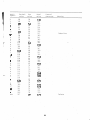
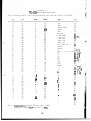
CONTENTS
SECTION
I,
PAGE
INSTALLATION .....................................................
1
1.1
1.2
1.3
1.4
1.5
Introduction .....................................................
Unpacking the TPC-2000 ...........................................
Setup And How To Get TPC-2000 Started ............................
Routine Operating Instructions ...................................
System Shutdown ..................................................
1
1
2
5
6
II
SYSTEM DESCRIPTION ...............................................
7
2.1
Introduction .....................................................
7
2.2
2.3
Hardware Overview ................................................
Software Overview ................................................
7
9
III
CP/M OPERATING SYSTEM ............................................
10
3.1
3.2
3.2.1
3.3
3.4
3.4.1
3.4.2
General Description ..............................................
Function Description Of CP/M .....................................
File References ..................................................
Switching Disks ..................................................
The Form Of Built-in Commands ....................................
ERA afn <cr> .....................................................
DIR afn <cr> .....................................................
10
11
12
14
14
14
15
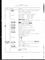
3.4.3 REN ufn1=ufn2 <cr> ............................................... 15
3.4.4 SAVE n ufn <cr> .................................................. 16
3.4.5 TYPE ufn <cr> .................................................... 17
3.5 Line Editing And Output Control .................................. 17
3.6
3.6.1
3.6.2
3.6.3
3.6.4
3.6.5
3.6.6
3.6.7
Transient Commands ...............................................
STAT <cr> ........................................................
ASM ufn <cr> .....................................................
LOAD ufn <cr> ....................................................
PIP <cr> .........................................................
ED ufn <cr> ......................................................
SYSGEN <cr> ......................................................
SUBMIT ufn parm#1 ... parm#n <cr> ................................
18
19
20
21
22
29
31
32
3.6.8 DUMP ufn <cr> .................................................... 34
3.6.9 MOVCPM <cr> ...................................................... 34
3.7
BDOS Error Messages .............................................. 36
IV
TPC-2000 SOFTWARE UTILITIES ......................................
38
4.1
4.2
REFORM ........................................................... 38
DCHECK ........................................................... 39
SECTION
PAGE
4.3
4.4
4.5
4.6
4.7
4.8
MODE .............................................................
DCOPY ............................................................
SETUP ............................................................
MTS ..............................................................
CRTEST ...........................................................
FUNCTION .........................................................
V
TPC-2000 HARDWARE ................................................ 47
5.1
5.2
5.3
5.4
5.5
5.6
Serial Port (SIO or DART) ........................................
Parallel Port (PIO) ..............................................
Counter Timer Circuit (CTC) ......................................
Floppy Disk Formatter/Controller (FDC) ...........................
CRT Controller (CRTC) ....^.......................................
Serial Keyboard Encoder (SKE) ....................................
VI
KEYBOARD ......................................................... 49
6.1 Numeric Pad Functions ............................................
6.2 Alphanumeric Keypad ..............................................
6.2.1 General ..........................................................
6.2.2 RESET ............................................................
6.2.3 SPACE BAR ........................................................
6.2'. 4 SHIFT ............................................................
6.2.5 CTRL .............................................................
6.2.6
ESC
..............................................................
6.2.7
DEL
..............................................................
6.2.8 BREAK ............................................................
6.3 LED Indicator .............................................. ...^-...
6.3.1 Programmable Phrase ..............................................
6.3.2 SHIFT LOG ........................................................
6.3.3 CAP LOG ..........................................................
6.3.4 LOCAL ............................................................
6.4 Special Function Keypads .........................................
6.4.1 Cursor Movement ..................................................
6.4.2 EDIT Functions ...................................................
6.5 Others. ...........................................................
6.5.1 Visual Attributes ................................................
6.5.2 Function Key .....................................................
6.5.3 Control Character Codes ..........................................
6.5.4 Summary ............................................................
40
41
43
44
45
45
47
47
47
48
48
48
49
50
50
50
50
50
50
50
51
51
51
51
52
52
52
52
52
54
55
55
56
56.
57
APPENDICES
APPENDIX
A
B
C
D
E
F
H
PAGE
The ASCII Character Set ..........................................
Input/Output Port Assignment .....................................
Functions Table Li st .............................................
TPC-2000 Keystrokes And Codes ....................................
System Startup Checklist .........................................
Interpretation Of Disk Controller Status .........................
Troubleshooting ..................................................
59
62
64
66
67
68
70
FIGURES
1-1
1-2
1-3
2-1
6-1
6-2
6-3
Front Panel ...................................................... 2
Rear Panel ....................................................... 2
Diskette Insert .................................................. 5
System Block Diagram ............................................. 8
TPC-2000 Standard Keyboard Layout ................................ 49
Numer ical Keypad ................................................. 50
LED Indicator .................................................... 51
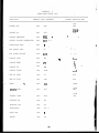
TABLES
4-1
Disk Format Set For TPC-2000 ..................................... 39
SECTION I
INSTALLATION
1.1 Introduction
This manual is designed for people who want to learn to program the
computer or to bring economy and efficiency to his business. With this
manual and a TATUNG TPC-2000 desktop small business computer, and a bit
of your time and attention, you will find that there is nothing
difficult about using TPC-2000.
The TPC-2000 is the ideal system for the small business with data
processing requirements. This system allows streaming of time consuming
tasks, such as inventory control, order entry, and billing. It runs the
CP/M V2.2 Operating System and all utilities and application softwares
designed for CP/M.
.
Simply add a TTL INPUT/OUTPUT board onto TPC-2000, the TPC-2000 becomes
an industrial controller for such as ROBOT, chemial PH control ... etc.
As computing requirements grow, the TPC-2000 can become a workstation
of the host computer, with its built-in floppy drive serving as local
storage. Because the TPC-2000 has a function which allows it to accept
down-loads from the host computer, it can work as a workstation with or
without its disk drive(s).
When the TPC-2000 functions as a terminal of a host computer, it can
simulate other types of terminals by sending terminal control code
tables from the host computer.
1.2
Unpacking the TPC-2000
Carefully unpack the TATUNG TPC-2000 computer. Do not use a sharp or
pointed instrument to open the packing box, as this may pierce the
protective covering and scratch the finish on the machine. Carefully
remove the computer from the shipping carton and inspect for external
damage. If any damage is noted, please notify TATUNG and file a-claim
for damages with the shipping Carrier. Do not discard the shipping
carton and any of package related parts as these should be used to
return (Before r e t u r n , ensure that the package method is the same as
TATUNG original package you received) the machine to TATUNG in the
event of a hardware malfunction.
Assuming that there is no damage, position the computer in such a way
that there is clear access to the front and rear panels. Ensure that
the ventilation ports on £he sides are clear and unobstructed.
jf
|
|
|
|
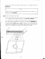
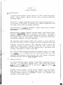
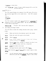
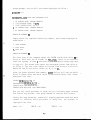
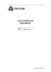
1.3 Setup and How to Get TPC-2000 Started
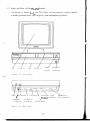
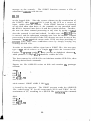
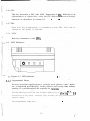
As shown in Figure 1-1, the TPC-2000 microcomputer system should
include processor unit, CRT display, and detachable keyboard.
/
CRT
Drive B
CPU
Drive A
Power
Switch
Keyboard
Connector
Figure 1-1 Front Panel
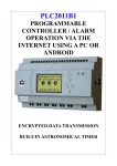
Fuse / AC Outlet \ DIP Switch\ Centronic Type
Expansion
Bus Connector
xPrinter Connector
Monitor
8" Drive
Connector Connector RS-232 Port
Figure 1-2 Rear Panel
Use the supplied cables to interconnect these separate parts, be very
careful and make sure that all connectors are pluged in right
direction. N e x t , plug the TPC-2000 end of the computer's power cord
into the TPC-2000 ( on the rear left side of the TPC-2000 ), and the
other end into a three-prong grounded wall outlet.
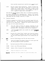
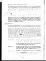
Now the TPC-2000 is completely set up. turn the power on ( the power
switch is on the upper right corner of the front panel ), you will hear
a beep sound and an underline cursor should appear at upper left corner
of the screen.
Get the system diskette from its package and insert it into drive A,
the built-in d r i v e on the right side of the system, with the label
facing up and the oval cutout toward the back pf the disk drive, clamp
the front lever down. Depress "F1" key, this sequence is called System
Boot. In this sequence, the disk drive will make whirring and clacking
noises as CP/M-80 is loaded into memory. The first thing that CP/M-80
does after it is loaded into memory is to display the following message
on your screen:
6MK TATUNG DOS VERS. V.W
A>
'
.
.
,
.
.
.
.
,
.
.
, '
where 64K indicate that the memory size of TPC-2000, the version
number, represented above by V.W tells you the revision level of the
Tatung version that you own. "A>" is system prompt to tell you CP/M-80^
is ready to read a command from your keyboard. It also tells you that
drive A is your "default" drive. That means that until you tell CP/M-80
to do otherwise, it looks for program and data files on the diskette in
d r i v e A.
,
.
;
If your screen display doesn't conform to the above description, don't
worry. Turn the power off, then check each connector and system diskette. If everything seems all right, you may do the system boot sequence
again and the " 6HK TATUNG DOS VERS 2.24* " will display on screen.
Otherwise you may call your dealer who will give you the best answer.
TATUNG recommends that you make a backup copy of the TPC-2000 system
disk.and use that copy to perform all operation, the original disk
should be stored in a safe place.
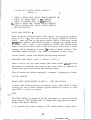
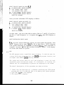
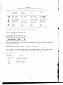
In order to check the function of the distribution diskette and some
basic functions of the TPC-2000, type the following command to display
a list, of the files on the distribution diskette :
.
DIR
<cr>
The screen should display like following format :
A •• PIP
A •• DUMP
A • LOAD
A •• MODE
A •• F
A •• MTS
COM : ED
COM : STAT
COM : SUBMIT COM : ASM
COM : REFORM COM : SYSGEN
COM : DCOPY
COM : SETUP
DAT : FUNCTION COM : MOVCPM
COM : XSUB
COM
COM * DDT
COM * F1
COM I DCHECK
COM : CRTEST
COM * PRTEST
COM
COM
COM
COM
COM
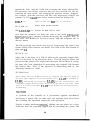
In order to obtain a back-up copy of system diskette, you should insert
a blank diskette in drive B then format and generate system on this
diskette ( See Section 5 ). Copy files from your original disk onto
your backup disk, type the command :
PIP B:=A:*.*[V] <cr>
The system will copy all disk files from the disk A onto disk B, and
verifies that each file has been copied correctly. The name of each
file is displayed at the CRT as the copy operation proceeds. When this
is completed the system will again display the prompt symbol "A>". You
n6w have a complete copy of -your original disk. Release the front
levers for both drives and remove both disks from their drives. Store
the original disk in safe place. Place the copied disk into drive A,
and clamp the front lever. Type a CTRL-C. ( Note: The character """
represents the Control function and "C is typed by holding down the
control key while typing a C ) The system should respond with the "A>"
prompt symbol.
If you are using an external hard-copy printer, connect its cable to
Centronic type printer jack on the rear of the computer. Plug in the
printer's power cord and turn on its power switch. Make any other
necessary settings on the printer in accordance w i t h the printer's
operating manual. Refer to the SETUP Command if it is necessary to
change the Operating System. Test the printer by typing the command :
PIP LST:=A:DUMP.ASM<cr>
If all is working correctly, the printer will begin typing a copy of
the CP/M DUMP source program. Save this printout for future reference.
This completes the initial setup and checkout. If you have encountered
any difficulties, refer to Appendix F and Appendix G of this manual.
Assuming that no difficulties have been encountered to this point, you
can now begin using your computer. It is suggested that you familiarize
yourself with the rest of this manual prior to starting any major
operations.
NOTE
Always remove your diskettes from the disk drives before you
turn off your TPC-2000.
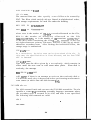
1.4
Routine Operating Instructions
For the initial startup and checkout of your system, consult Section
1.3 of this manual to ensure that your computer is operational.
After the system is completely checked out and operating correctly, use
the following instructions as a guide for routine system startup.
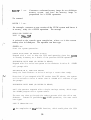
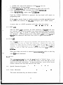
Consult Figures 1-1 through 1-3, if required, for positioning and
placement information. The following instructions assume that your
system uses a standard CRT display and a detachable keyboard.
<J
Figure 1-3 Diskette Insert
Turn on the power switch on the front panel of the TPC-2000. If
appropriate, turn on the power switch on the printer or other
peripheral device(s).
Release the front lever of both drives, Insert a system disk (a disk
containing the CP/M Operating System program on tracks 0, 1 and 2) in
the drive A with the m a n u f a c t u r e r ' s label facing on. R e f e r to Figure
1-3 for the correct method of inserting the disk. And clamp the front
lever of drive A.
Make sure your system is set on by real panel switch (please refer
Appendix B) and press "F1" keys to cause the system to "AUTO Boot", the
system will display the message :
TATUNG DOS VERS V.W*
and then the symbol "A>" will appear. This is the indication that the
Operating System program has successfully loaded and is controlling the
TPC-2000'S operation. At this point you may enter the appropriate CP/M
commands to perform the processing required.
1.5
System Shutdown
There is only special precaution which should be observed when you are
finished with the computer and are preparing to turn it off.
Power to the computer should not be turned on or off with diskettes in
the disk drives. Therefore, before t u r n i n g off the power switch,
release both front levers and remove the diskette or diskettes. Failure
to observe this precaution could allow an unpredictable magnetic field
to erase or alter a small part of the information on the diskette. The
potentially disastrous result of such an alteration might not be
discovered until some time later.
NOTE
Don't switch on TPC-2000 within 30 seconds after power off TPC-2000
or you will break down the power supply of TPC-2000
SECTION
II
SYSTEM DESCRIPTION
2.1
Introduction
A typical microcomputer system consists of a CPU (Central Processing
U n i t ) , input, output, storage devices, and a program called the
Operating System.
The CPU is a single integrated circuit chip, called microprocessor, it
is the heart of the system. Its function is to obtain instructions from
the memory and perform the desired operations.
The input device is usually a keyboard. Typical output devices includes
CRT(Cathode Ray Tube) and printer.
Storage devices include computer's internal Random Access Memory (RAM),
Read Only M e m o r y ( R O M ) , and the magnetic floppy disks. The RAM is
volatile storage, it must have power applied to retain its information.
The floppy disks are non-volatile storage because they retain their
information regardless of power application.
The Operating System program enables the computer to accept directions
from the user and it must be loaded into the computer before the
computer can do the function. The Operating System accepts and
interprets commands from the keyboard, reads from and writes to the
floppy disks, communicates with the output device(s), and keeps track
of where information is stored on the disks.
The TATUNG TPC-2000 Integrated desktop microcomputer system is a single
user system, it is a compact and very attractive desktop unit. The
standard system consists of the processor unit, CRT display, detachable
keyboard and dual slim line mini-floppy disk drives.
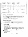
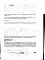
2.2
Hardware Overview
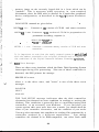
The TATUNG TPC-2000 computer includes a Z80A (4MHz) microprocessor, two
slim line 5 1/4" mini-floppy diskette drives. Each system also include
64K bytes RAM and 4K bytes ROM for main memory, 4K bytes RAM and 2K
bytes ROM for display memory.
Standard system includes a serial RS-232C interface port for printer;
baud rate of 110, 300, 600, 1200, 2400, 4800, 9600, or 19200 bps can be
selected through software or by hardware switch; one Centronics type
interface for parallel printer.
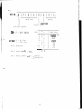
MULTIPLEXER
Figure 2-1
DISPLAY
RAM
System Block Diagram
The TPC-2000 detachable keyboard has been designed for easy to used. It
has 93 sculptured keys arranged in standard typewriter format, and
includes alpha lock, 18-key numeric pad with decimal and 6 programmable
function keys which can be used to implement automatically complicated
and repetitive operation with a single key stroke.
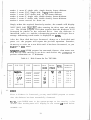
The disk drives incorporated in your TPC-2000 vary from model to model,
according to the followings:
1> single side, 96 TPI — 360K Bytes of formatted storage per drive.
2> double side, 96 TPI — 720K Bytes of formatted storage per drive.
A wide range of options is available with the TPC-2000, each is fully
supported by TATUNG.
* Color monitor display unit
* Graphic display board
* 8" floppy drive :
TPC-2000 can be added with 2 additional drives (if TPC-2000 already
has 2 mini-floppy drives), or U drives (if TPC-2000 does not have any
mini-floppy drives). Each 8" drive has a 616K (single side) or 1.2MB
(double side)
« Virtual disk :
Each virtual disk has 256KB capacity. The TPC-2000 can be added up to
8 virtual disk boards
* Hard disk :
TPC-2000 can be added up to 4 sets of 5 1/M" or hard disk drives.
8
There are 6.6 MB/drive, 13.3 MB/drive, and 2? MB/drive options for 5
1/4" Winchester hard disk.
* Serial interface board :
Each interface board has 14 RS-232C serial ports. The TPC-2000 can be
added up to 2 boards.
* TTL input/ouput board :
Each I/O board has 64 input/ouput points. TPC-2000 can be added with
2 input/output board.
OPERATING CONDITIONS ———
Power requirement
Power consumption
Operating Temperature
Humidity
Weight
Dimensions (mm)
110V or 220V +/- 10%, 50 or 60 Hz
less than 100VA
10°C - 40°C
20% - 80% Noncondensing
12 Kg
450(W) X 42800 X 620(D)
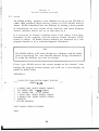
2.3 Software Overview
The term software refers to whatever program will be used with the
computer. This includes the CP/M Operating System program, the various
utility programs provided with the computer and any program written by
the user or acquired by other means.
The program stored in the ROM is called "Firmware", since it is program
material, but not easily alterable. The ROM firmware will be considered
a subset of the software, since it is program material. The program in
the ROM was written by TATUNG and is required in order to perform the
most basic machine functions.
Two operating systems are available for the integrated TPC-2000 system;
the CP/M V2.2 for single users and the CP/NET for local networks. Both
operating systems support a wide range of application languages.
OPERATING SYSTEM : CP/M V.VV, CP/NET
i
UTILITIES
: KSAM, DATASTAR, SUPERSORT, WORDSTAR, SUPERCALC,
VEDIT, BISYNC, L80, LIB80, DBASE II
LANGUAGES
: ASM, M80, MAC, FORTRAN, CBASIC, CB80, MBASIC,
PASCAL/M , PASCAL/MT+ , COBOL80
SECTION III
CP/M OPERATING SYSTEM
3.1
General Description
CP/M is a monitor control program for microcomputer system development
w h i c h uses IBM-compatible f l e x i b l e disks for backup storage. C P / M
provides a general environment for program construction, storage, and
e d i t i n g , along w i t h assembly and program check-out facilities. It
also provides rapid access to programs through a comprehensive file
management package. The file subsystem supports a named file structure
, allowing dynamic allocation of file space as well as sequential and
random file access. Using this file system, a large number of distinct
programs can be stored in both source and machine executable form.
C P / M also supports a powerful context editor, Intel-compatible
assembler, and debugger subsystems. Optional software includes a
powerful Intel-compatible macro assembler, symbolic debugger, along
with various high-level languages. When coupled with CP/M's Console
Command Processor, the resulting f a c i l i t i e s equal or excel similar
large computer facilities.
CP/M is logically divided into several distinct parts:
BIOS
BDOS
CCP
TPA
Basic I/O System (hardware dependent)
Basic Disk Operating System
Console Command Processor
Transient Program Area
The BIOS provides the p r i m i t i v e operations necessary to access the
diskette drives and to interface standard peripherals (teletype, CRT,
Paper Tape R e a d e r / P u n c h , and user-defined peripherals), and can be
tailored by the user for a n y particualr h a r d w a r e e n v i r o n m e n t by
"patching" this portion of CP/M. The BDOS implements disk allocation
strategies which provide fully dynamic file contruction while minimizing head movement across the disk during access. Any particular file
may contain any number of records, not exceeding the size of any
single disk. In a standard C P / M system, each disk can contain up to
6') distinct files. The BDOS has entry points which include the
following primitive operations which can be programmatically accessed:
X
SEARCH Look for a particular disk file by name.
OPEN
Open a file for further operations.
CLOSE
Close a file after processing.
RENAME Change the name of a particular file.
READ
Read a record from a particular file.
10
WRITE
SELECT
Write a record onto the disk.
Select a particular disk drive for further operations.
The CCP provides symbolic interface between the user's console and the
r e m a i n d e r of the C P / M system. The CCP reads the console device and
processes commands which include listing the file directory, printing
the contents of files, and controlling the operation of transient
programs, such as assemblers, editors, and debuggers.. The standard
commands which are available in the CCP are listed in a following
section.
The last segment of CP/M is the area called the Transient Program Area
(TPA). The TPA holds programs which are loaded from the disk under
command of the CCP. During program editing, for example, the TPA holds
the CP/M text editor machine code and data areas. Similarly, programs
created under CP/M can be checked out by loading and executing these
programs in the TPA.
It should be mentioned that any or all of the C P / M component
subsystems can be "overlayed" by an executing program. That is, once a
user's program is loaded into the T P A , the CCP, BDOS, and BIOS areas
can be used as the program's data area. A "bootstrap" loande is
programmatically accessible whenever the BIOS portion is not
overlayed; thus, the user program need only branch to the bootstrap
loader at the end of execution, and the complete C P / M monitor is
reloaded from disk.
3.2
Functional Description of CP/M
The user interacts win CP/M primarily through the CCP, which reads and
interprets commands entered through the console. In general, the CCP
addresses one of seveal disks which are online (the standard system
addresses up to four different disk drives). These disk drives are
labelled A , B , C , and D. A disk is "logged in" if the CCP is c u r r e n t l y
addressing the disk. In order to clearly indicate w h i c h disk is the
currently logged disk, the CCP always prompts the operator with the
disk name followed by the symbol "<" indicating that the CCP is ready
for another command. Upon initial start up, the C P / M system is
brought in from disk A. and the CCP displays the message
xxK CP/M VER m.m
where xx is the memory size (in kilobytes) which this C P / M system
manages, and m.m is the C P / M version number. All C P / M systems are
initially set to operate in a 16k memory space, but can be easily
reconfigured to it any memory size on the host system (see the MOVCPM
transient command). Following system signon, CP/M automatically logs
11
in disk A, prompts the user with the symbol "A>" (indicating that CP/M
is currently addressing disk "A"), and waits for a command. The
commands are implemented at two levels: built-in commands and
transient commands. Nearly all of the commands reference a particular
file or group of files. The form of a file reference is specified
below.
3.2.1 File References
A file reference identifies a particular file or group of files on
particular disk attached to CP/M. These file references can be either
"unambiguous" ( u f n ) or "ambiguous" (afn). An unambiguous file
reference uniquely identifies a single file, while an ambiguous file
reference may be satisfied by a number of different files.
File referneces consist of two parts: the primary name nd the
secondarty name. Although the secondary ame is optional, it usually
is generic; that is, the secondary name "ASM," for example, is used to
denote that the file is an assembly language source file, while the
primary name distinguishes each particular source file. The two names
are se par ted by a "." as show below:
PPPPPPPP.sss
where pppppppp represents the primary name of eight characters or
less, and sss is the secondary name of no more than three characters.
As mentioned above, the name
pppppppp
is also allowed and is equivalent to a secondary name consisting of
three blank. The characters used in specifying an unambiguous file
reference cannot contain any of the special characters
<
>»
X /
• . - 9 * Lr J
i
| | . — •
while all alphanumerics remaining special characters are allowed.
An ambiguous file reference is used for directory search and pattern
matching. The form of an ambiguous file reference is similar to an
unambiguous reference, except the symbol "?" may be interspersed
throughout the primary and secondary names. In various c o m m a n d s
throught CP/M, the "?" symbol matches any character of a file name in
the "?" position. Thus, the ambiguous reference
X?Z.C?M
12
ppppppp.
and
*.sss
ppppppp.???
and
???????.sss
respectively.
are abbreviations for
As an example,
DIR ».«
is interpreted by the CCP as a command to list the names of all disk
files in the directory, while
DIR X.Y
searches only for a file by the name X.Y . Similarly, the command
DIR X?Y.C?M
,
causes a search for all (unambiguous) file names on the disk which
satisfy this ambiguous reference.
The following file names are valid unambiguous file references:
X
A.Y
XYZ
XYZ.COM
GAMMA
GAMMA.1
As an added convenience, the programmer can generally specify the disk
drive name along with the file name. In this case, the drive name is
give as a letter A through D followed by a colon (:). The specified
drive is then "logged in" before the file operation occurs. Thus, the
following are valid file names with disk name prefixes:
A:X.Y
B-.SYZ
C:GAMMA
It should also be noted that all alphabetic lower case letters in file
and drive names are always translated to upper case when they are
processed by the CCP.
13
3.3
Switching Disks
The operator can switch the currently logged disk by typing the disk
drive name (A,B,C,orD) followed by a colon (:) when the CCP is waiting
for console input. Thus, the sequence of prompts and commands shown
below might occur after the Cp/M system is loaded from disk A:
64K CP/M VER 2.2
List all files on disk A.
A>DIR
A: SAMPLE ASM : SAMPLE PRN : DUMP
A: PIP
COM : STAT
COM
Switch to disk B.
List all "ASM" files on B.
A>B:
B>DIR *.ASM
B: DUMP
ASM : FILES
ASM : REFORM ASM : DCOPY
ASM
Switch back to A.
B>A:
3.4
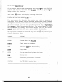
COM : SYSGEN COM
The Form of Built-in Commands
Built-in commands are a part of th CCP program itself, while transient
commands are loaded into the TPA from disk and executed. The built-in
commands are
ERA
DIR
REN
SAVE
TYPE
Erase sepcified files.
List file names in the directory.
Rename the speicified file.
Save memory contents in a file.
Type the contents of a file on the logged disk.
3.4.1 ERA afn <cr>
The ERA (erase) command removes files from the currently logged-in
disk (i.e., the disk name c u r r e n t l y prompted by CP/M preceding the
•">"). The files which are erased are those which satisfy the ambiguous
file reference afn. The following examples illustrate the use of ERA:
ERA X.Y
The file named X.Y on the currently logged disk is removed from the disk directory, and the space is returned.
ERA X.*
All files with primary name X are removed from the
current disk.
ERA *.ASM
All files with secondary name
current disk.
ERA X?Y.C?M
All files on the current disk which satisfy the ambiguous
reference X?Y.C?M are deleted.
ERA *.*
Erase all files on the current disk (in this case the CCP
prompts the console w i t h the message "ALL FILES (Y/N)?"
which requires a Y response before files are actually
removed).
E R A B:*.PRN
All f i l e s on d r i v e B w h i c h s a t i s f y the ambiguous
reference ????????.PRN are deleted, independently of the
currently logged disk.
ASM
are removed from the
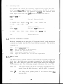
I.U.2 DIR afn <cr>
The DIR (directory) command causes the names of all files which
satisfy the ambiguous file name afn to be listed at the console
device. As special case, the command
DIR
lists the files on the currently logged disk (the command "DIR" is
equivalent to the command "DIR*.*"). Valid DIR commands are shown
below.
DIR X.Y
DIR X?Z.C?M
DIR ??.Y
Similar to other CCP commands, the afn can be preceded by a drive
name. The following DIR commands cause the selected drive to be
addressed before the directory search takes place.
DIR B:
DIR B:X.Y
DIR B:*.A?M
If no files can be found on the selected diskette which satisfy the
directory request, the then message "NOT FOUND" is typed at the
console.
3.H.3 REN ufn1=ufn2 <cr>
The REN (rename) command allows the user to change the names of files
on disk. The file satisfying u f n 2 is changed to u f n l . The c u r r e n t y
15
logged disk is assumed to contain the file to rename (ufnD. The CCP
also allows the user to type a left-directed arrow instead of the
equal sign.
Examples of the REN command are
REN X.Y=Q.R
REN XYZ.COM=XYZ.XXX
The file Q.R is changed to X.Y.
The file XYZ.XXX is changed to XYZ.COM.
The operator can preceded either ufnl or ufn2 (or both) by an optional
d r i v e address. Given that ufn 1 is preceded by a d r i v e name, then
u f n 2 is assumed to exist on the same drive as u f n l . Similarly, if
u f n 2 is preceded by a drive names,then u f n l is assumed to reside on
hat drive as well If both u f n l and u f n 2 are proceded by d r i v e n a m e s ,
then the same d r i v e must be specified in both cases. The following
REN commands illustrate this format.
REN A:X.ASM=Y.ASM
The file Y.ASM is changed to X.ASM on drive A.
REN B:ZAP.BAS=ZOT.BAS The file ZOT.BAS is changed to ZAP.BAS on
d r i v e B.
REN B:A.ASM=BAK
The file A.BAK is renamed to A.ASM on drive B.
If the file ufn is already present, the REN command will respond with
the error "FILE EXISTS" and not perform the change. If ufn2 does not
exist on the specified diskette, then the message "NOT FOUND" is
printed at the console.
SAVE n ufn <cr>
The SAVE command places n pages (256-byte blocks)onto disk from the
TPA and names this file u f n . In CP/M distribution system, the TPA
starts at 100H(hexadecimal),which is the second page of memory. Thus,
if the user's program occupies the area from 100H through 2FFH, the
SAVE command must specify 2 pages of memory. The machine code file
can be subsequently loaded and executed. Examples are:
SAVE 3 X.COM
Copies 100H through 3FEH to X.com.
SAVE 40 Q
Copies 100H through 28FFH to Q ( note that
28 is the page count in 28FFH, and that
28H=2*16+8=40 decimal ).
SAVE 4 X . Y
Copies 10H through 4FFH to X . Y .
The SAVE command can also specify a disk drive in the afn portion of
16
te command, as shown below.
SAVE 10 B:ZOT,COM
Copies 10 pages (100H through AFFH) to the file
ZOT.COM on drive B.
3.M.5 TYPE ufn <cr>
The TYPE command displays the contents of the ASH source file ufn on
the currently logged disk at the console devie. Valid TYPE commands
are
TYPE X.Y
TYPE X.PLM
TYPE XXX
"*••'
The TYPE command expands tabs (ctl-I characters), assumming tab
positions are set at every eighth column. The ufn can also reference
a drive name as shown below.
TYPEB:X.PRN
3.5
The file X.PRN from drive Bis displayed.
Line Editing and Output Control
The CCP allows certain line editing functions while typing command
• lines.
rubout
Delete and echo the last character typed at the console.
ctl-U
Delete the entire line typed at the console.
ctl-X
(Same as ctl-U)
ctl-R
Retype current command line:types a "clean line" following
character deletion with rubouts.
ctl-E
Physical <#ul of line :carriage is returned, but line is not
sent until the carriage return key is depressed.
ctl-C •
CP/M system reboot (warm start)
ctl-Z
End input from the console (used in PIP and ED).
•i*-1
The control functions ctl-P and ctl-S affect console output as shown
below .
ctl-P
Copy all subsequent console output to the currently assigned
list device (see the STAT command). Output is sent to list
17
device and the console device until the next ctl-P is typed.
ctl-S
Stop the console output temporarily. Program execution and
output continue when the next character is typed at the
console (e.g., another ctl-S). This feature is used to stop
output on high speed consoles, such as CRT's, in order to
view a segment of output before continuing.
Note that the ctl-key sequences shown above are obtained by depressing
the control and letter keys simultaneously. Further, CCP command
lines can g e n e r a l l y be up to 255 characters in length; they are not
acted upon until the carriage return key is typed.
3.6
Transient Commands
Transient c o m m a n d s are loaded from the currently logged disk and
executed in the TPA. The transient commands defined for execution
under the CCP are shown below. Additions can easily be defined by the
user (see the LOAD command definition).
STAT
List the number of bytes of storage remaining on the
currently logged disk, provide statistical information about
particular files, and display or alter device assignment.
ASM
Load the CP/M assembler and assemble the specified progeam
from disk.
LOAD
Load the file in Intel "hex" machine code format ana produce
a file in machine executable form which can be loaded into
the TPA (this loaded program becomes a new command under the
CCP).
DDT
Load the CP/M debugger into TPA and start execution.
PIP
Load the Peripheral Interchange Program for subs equent disk
file and peripheral transfer operations.
ED
Load and execute the CP/M text editor program.
SYSGEN
Create a new CP/M system diskette.
SUBMIT
Submit a file of commands for batch processing.
DUMP
Dump the contents of a file in hex.
MOVCPM
Regenerate the CP/M system for a particular memory size.
18
Transient commands are specified in the same manner as built-in
commands and additional commands can be easily defined by the user.
As an added convenience, the transient command can be preceded by a
drive name, which causes the transient to be loaded from the specified
drive into the TPA for execution. Thus, the command
B:STAT
causes CP/M to temporarily "log in" drive B for the source of the STAT
transient, and then return to the original logged disk for subs equent
processing.
The basic transient commands are listed some examples below, for
detail refer CP/M Operating System User's Manual.
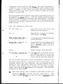
1 STAT <cr>
The STAT command provides general statistical information about file
storage and device assignment. It is initiated by typing one of the
following forms:
STAT <cr>
STAT "command line" <cr>
;
Special forms of the "command line" allow the current device
assignment to be examined and altered as well. The various command
lines which can be specified are shown below with an explanation of
each form shown to the right.
STAT <cr>
If the user types an empty command line, the STAT transient calculates
the storage remaining on all active drives, and prints a message
X-.R/W, SPACE :nnnK
X:R/0,SPACE:nnnK
or
for each active drive x,.where R/W indicates the drive may be read or
written, and R/0 indicates the drive is read only (a drive becomes R/0
by explicitly setting it to read only, as shown below, or by
inadvertantly changing diskettes without performing a warm start).
The space remaining on the diskette in drive x is given in kilobytes
by nnn.
STAT x : < c r >
If a drive name is given, then the drive is selected before the
storage is computed. Thus, the command "STAT B: w could be issued
while logged into drive A, resulting in the message
19
BYTES REMAINING ON BrnnnK
STAT afn <cr>
The command line can also specify a set of files to be scanned by
STAT. The files which satisfy afn are listed in alphabetical order,
with storage requirements for each file under the heading
RECS
BYTS
EX
D:FILENAME.TYP
rrrr
bbbK
ee
d:pppppppp.sss
where rrrr is the number of 128-byte records allocated to the file,
bbb is the number of kilobytes allocated to the f i l e
(bbb=rrrr« 128/1024), ee is the number of 16K extensions (ee=bbb/l6), d
is the drive name containing the file (A....Z), pppppppp is the (up
to) eight-character primary file name, and sss is the (up to) threecharacter secondary name. After listing the individual files, the
storage usage is summarized.
STAT x:afn <cr>
As a convenience, the drive name can be given ahead of the afn. In
this case, the specified drive is first selected, and the form "STAT
afn" is executed.
STAT x:=R/0 <cr>
This form sets the drive given by x to read-only, which remains in
effect until the next warm or cold start takes place. Whena disk is
read-only, the message
BDOS ERR ON xrREAD ONLY
will appear if there is an attempt to w r i t e to the read-only disk x.
C P / M waits until a key is depressed before performing an automatic
warm start (at which time the disk becomes R/W).
3.6.2 ASM ufn <cr>
The ASM command loads and executes the CP/M 8080 assembler. The ufn
specifies a source fil econtaining assembly language statements where
the secondary name is assumed to be ASM, and thus is not specified.
The following ASM commands are valid:
ASM X
\
ASM GAMMA
20
The two-pass assembler is automatically executed. If assembly error
occur during the second pass, the errors are printed at the console.
The assembler produces a file
X.PRN
where x is the primary name specified in the ASM command. The P R N
file contains a listing of the source program ( w i t h imbedded tab
characters if present in the source program), along with machine code
generated for each statemnt and diagnostic error messages, if any.
The PRN file can be listed at the console using th TYPE command, or
sent to a peripheral device using PIP (see the PIP command structure
below). Note also that the PRN f i l e contains the original source
program, augmented by miscellaneous assembly information in the
leftmost 16 columns (program addresses and hexadecimal machine code,
for example). Thus, the PRN file can serve as a backup for the
original source file: if the source file is accidently removed or
destroyed, the P R N file can be edited (see the ED operator's guide)
by removing the leftmost 16 characters of each line (this can be done
by issuing a singleeditor"macro" command). The resulting file is
identical to the original source file and can be renamed (REN) from
PRN to ASM for subsequent editing and assembly. The file
x.HEX
is also produced which 8080 machine language in Intel "hex" format
suitable for subsequent loading and.execution (see the LOAD command).
For complete details of CP/M's assembly language program, see the
"CP/M Assembler language (ASM) User's Gudie."
Similar to other transient commands, the source file for assemly can
be taken from an alternate disk by prefixing the assembly language
file name by a disk drive name. Thus, the command
ASM B:ALPHA <cr>
loads the assembler from the currently logged drive and operates upon
the source program ALPHA.ASM on drive B. The HEX and PRN files are
also placed on drive B in this case.
3.6.3 LOAD ufn <cr>
the LOAD command reads the file ufn, which is assumed to contain "hex"
format machine code, and produces a memory image file which oan be
subsequenly executed. The file name ufn is assumed to be of the form
21
x.HEX
and thus only the name x need be specified in the command, The LOAD
command creates a file named
x.COM
which marks it as containing machine executable code. The file is
actually loaded into memory and executed when the user types the file
name x immediaietly after the prompting character ">" printed by the
CCP.
In general, the CCP reads the name x following the prompting character
and looks for a built-in function name. If no function name is found,
th CCP searches the system disk directory for a file by the name
x.COM
If found, the machine code is loaded into the TPA, and the program
executes. Thus, the user need only LOAD a hex file once; it can be
subsequently executed any number of times by simply typing the primary
name. In this way, the user can "invent" new commands in the CCP.
(Initialized disks contain the transient commands as COM files, whin
can be deleted at the user's option.) The operation can take place on
an alternate drive if the file name is prefixed by a name. Thus,
LOAD BrBETA
brings the LOAD program into the TPA from the currently logged disk
and operates upon drive B after execution begins.
It must..be noted that the BETA.HEX file must contain valid Intel
format hexadecimal machine code records (as produced by the ASM
program, for example) which begin at 100H, the beginning of the TPA.
Further, the addresses in the hex records must be in ascending order;
gaps in unfilled memory regions are filled with zeroes by the LOAD
command as the hex records are read. Thus, LOAD must be used only for
creating CP/M standard "COM" files which operate in the TPA. Programs
which occupy regions of memory other than the TPA can be loaded under
DDT.
3.6.4 PIP <cr>
PIP is the CP/M Peripheral Interchange Program which implements the
basic media conversion operations necessary to load, print, punch,
copy, and combine disk files. The PIP program is initiated by typing
one of the following forms
22
1) PIP <cr>
2) PIP "command line" <cr>
In both cases, PIP is loaded into the TPA and executed. In case ( 1 ) ,
PIP reads command lines directly from the console, prompting with the
"*" character, u n t i l an empty command line is typed (i.e., a single
carrige r e t u r n is issued by the operator). Each successive command
line causes some media conversion to take place according to the rules
shown below. Form (2) of the PIP command is equivalent to the first,
except that the single command line given with the PIP command is
automatically executed, and PIP terminates immediately with no further
prompting of the console for input command lines. The form of each
command line is
destination = source//1, source//2,..., sourcetfn <cr>
where "destination" is the file or peripheral device to receive the
d a t a , and "source//1 ,...,source#n" represents a series of one or more
f i l e s or d e v i c e s w h i c h are copied f r o m l e f t to r i g h t to the
destination.
When multiple files are given in the command line (i.e, n > 1 ) , the
individual files are assumed to contain ASCII characters, with an
assumed CP/M end-of-file character (ctl^Z) at the end of each file
(see the o parameter to override this assumption). The equal symbol
( = ) can be replaced by a left-oriented arrow, if your console supports
this ASCII character, to improved readability. Lower case ASCII
alphabetics are internally translated to uppper case to be consistent
with C P / M file and device name conventions. Finally, the total
command line length cannot exceed 225 characters (ctl-E can be used to
force a physical carriage return for lines which exceed the console
width).
The destination and source elements can be unambiguous references toCP/M source files, with or without a preceding disk drive name. That
is, any file can be referenced with a preceding drive name (Ar,B:,C:,
or D : , ) which defineds the particular drive where the file may be
obtained or stored. ,When the drive name is not included, the currently
logged disk is assumed. Further,the destination file can also appear
as one or more of the source files, in which case the source file is
not altered until the entire concatenation is complete. If the
destination file already exists, it is removed if the command line is
properly formed (it is not removed if an error condition arises). The
following command lines (with explanations to the right) are valid as
input to PIP:
23
X=Y <cr>
Copy to file X from file Y, where X and
Y are unambiguous file names; Y remains
unchanged.
X=Y,Z; <cr>
Concatenate files Y and Z and copy to
file X, with Y and Z unchanged.
X.ASM=Y.ASM,Z.ASM,FIN.ASM <cr> Create the file X.ASM from the concatenation of the Y , Z , and FIN files
with type ASM.
NEW.ZOM=B:OLD.ZAP <cr>
Move a copy of OLD/ZAP from dirve B to
the currently logged diskjname the file
NEW.ZOT.
B:A.U=B:B.V,A:C.W,D.X <cr>
Concatenate file B.V from drive B with
C.W from drive A and D.X from the
logged disk; create the file A.U on
drive B.
For more convenient use, PIP allows abbreviated commads for transferring files between disk drives. The abberviated forms are
PIP X:=afn <cr>
PIP x:=y:afn <cr>
PIP x:=y: <cr>
PIP x:ufn=y: <cr>
The first form copies all files from the currently logged disk which
satisfy the afn to the same file names on drive x (x=A...Z). The
second form is equivalent to the first, where the source for the copy
is drive y (y=A...Z). The third form is equivalent to the command "PIP
u f n r y r u f n cr" which copies the file given by ufn from drive y to the
file ufn on drive x. The fourth form is equivalent to the third,
where the source disk is explicitly given by y.
Note that the source and destination disks must be different in all of
these cases. If an afn is specified, PIP lists each ufn which
satisfies the afn as it is being copied. If a file exists by the same
name as the destination file, it is removed upon successful completion
of the copy, and replaced by the copied file.
The following PIP commands give examples of valid
operations:
B:=*.COM
<cr>
disk-to-disk copy
Copy all files which have the secondary name
-: • -
"COM" to drive B from the current drive.
A:=B:ZAP.* <cr>
Copy all files which have the primary name "ZAP"
to drive A from drive B.
ZAP.ASM=B: <cr>
Equivalent to ZAP.ASM=B:ZAP.ASM
B:ZOT.COM=A: <cr>
Equivalent to B:ZOT.COM=A.ZOT.COM
B:=GAMMA.BAS <cr>
Same as B:GAMMA.BAS=GAMMA.BAS
B:=A:GAMMA.BAS <cr> Same as B:GAMA.BAS=A:GAMMA.BAS
The device names which can be used in PIP commands are
CON: The syste console device (used by CCP for communication with the
operator).
LST: The oudtput list device.
NUL:
Send 40 "nulls" (ASCII O's) to the device (this can be issued at
the end of punched output).
EOF:
end a CP/M end-of-file (ASCII ctl-Z) to the destination device
(sent automatically at the end of all ASCII data transfers
through PIP)..
INP: Special PIP input source which can be "patched" into the PIP
program itself:PIP gets the input data character-by-character by
CAlling location 103H, w i t h data returned in location 109H
(parity bit must be zero).
• . . ' . '
.,
'
,
. . .
OUT: Special PIP output destination which can be patched into the PIP
>. program:PIP CALLs location 106H with data in register C for each
character to transmit. Note that Ibcations 109H through 1FFH of
the PIP memory image are not used and can be replaced by special
;
purpose drivers using DOT (see the DOT operator's manual).
PRN:
Same as LST:, except that tabs are expanded at every eighth
character position, lines are numbered, and page ejects are
inserted every 60 lines, with an initial eject (same as [t8np]).
File and device names can be interspersed in the commands. In each
case, the specific device is read until end-of-file (ctl-Z for ASCII
files, and a real end of file or non-ASCII disk files).Data from each
device or file is concatenated from left to right until the last data
source has been read. The destination device or file is written using
the data from the source files, and an end-of-file character (ctl-Z)
25
is appended to the result for ASCII files. Note if the destination is
a disk f i l e , then a temporary file is created ($$$ secondary name)
which is changed to the actual file name only upon successful
completion of the copy. Files with te extension "COM" are always
assumed to be non-ASCII.
The copy operation can be aborted at any time by depressing any key on
the keyboard (a rubout suffices). PIP will respond with the message
"ABORTED" to indicate that the operation was not completed. Note that
if any operation is aborted, or if an error occurs during processing,
PIP removes any pending commands which were set up while using the
SUBMIT command.
Valid
PIP commands are shown below.
PIP LST:=X.PRN <cr>
Copy X.PRN to the LST device and
terminate the PIP program.
PIP
Start PIP for a sequence of commands
(PIP prompts with "*").
<cr>
<cr>
Concatenate three ASM files and copy
to the CON device.
*X.HEX= CON:,Y.HEX, PTR: <cr>
Create a HEX file by reading the CON
(until a ctl-Z is typed folloed by
d a t a f r o m PTR u n t i l a c t l - Z is
encountered.
*CON:=X.ASM,Y.ASM,Z.ASM
Single carriage return stops PIP.
<cr>
PIP LST:=NUL:,X.ASM,EOF:NUL: <cr> Send 40 nulls to the list device;
then copy the X.ASM file to the List
.
device, followed by an end-of file
(ctl-Z) and 40 more null characters.
The user can also specify one or more PIP parameters, enclosed in left
and eight square brackets, separated by zero or more blanks. Each
parameter affects the copy operation, and the enclosed list of
parameters must immediately follow the affected file or device.
Generally, each parameter can be followed by an optional decimal
integer value (the S and Q parameters are exceptions). The valid PIP
parameters are listed below
B
Block mode transfer: data is buffered by PIP until an ASCII x-off
character (ctl-S) is received from the source device. This
allows transfer of "data to a disk file from a coninuous reading
26
device, such as cassette reader. Upon receipt of the x-off, PIP
clears the disk buffers and returns for more input data. The
amount of data which can be buffered is dependent upon the memory
size of the host system (PIP will issue an error message if the
b u f f e r s overflow).
Dn
Delete characters which extend past column n in the transfer of
data to the destination from the character source. This parameter
is used most often to truncate long lines which are sent to a
(narrow) printer or console device.
E
Echo all transfer oprations to the console as they are being
per formed.
F
Filter form feeds from the file. All imbedded form feeds are
removed. The P parameter can be used simultaneously to insert new
form feeds.
H
Hex data transfer:all data is checked for proper Intel hex file
format. Nonessential characters between hex records are removed
during the copy operation. The console will be prompted for
corrective action in case errors occur.
I
Ignore "00" records in the transfer of Intel hex format file (the
I parameter automatically sets the H parameter).
L
Translate upper case alphabetics to lower case.
N
Add line numbers to each line transfered to the destination
starting at one, and incrementing by 1. Leading zeroes are
suppressed, and the number is followed by a colon. If N2 is
specified, then leading zeroes are included, and a tab is
inserted following the number. The tab is expanded if T is set.
0
Object file (non-ASCII) transfer: the normal CP/M end of file is
ignored.
Pn
Include page ejects at every n lines (with an initial page
eject). If n=1 or is excluded altogether, page ejects occur
every 60 lines. If the F parameter is used, form feed supression
takes place before the new page ejects are inserted.
Qs~z Quit copying from the source device or file when the string s
(terminated by ctl-Z) is encountered.
Ss~z Start copying from the source device when the string s is
encountered (terminated by ctl-Z). The S and Q parameters can be
27
used to "abstract" a particular section of a file (such as a
subroutine). The start and quit string s are always included in
the copy operation.
NOTE
the string s following the S and Q parameters are translated to
upper case by the CCP if form (2) of the PIP command is used.
Form (1) of the PIP invocation, however, does not perform the
automatic upper case translation.
1)
PIP <cr>
2)
PIP "command line" <cr>
Tn
Expand tabs (ctl-I characters) to every nth column during the
transfer of characters to the destination from the source.
U
Translate lower case alphabetics to upper case during the copy
operation.
V
Verify that data has been copied correctly by reading after the
write operation (the destination must be a disk file).
Z
Zero the parity bit on input for each ASCII character.
The following are valid PIP commands which specify parameters in the
file transfer:
PIP X.ASM=B:Cv] <cr>
Copy X.ASM from drive B to the current dive and v e r i f y that the data
was properly copied.
PIP LPT:=X.ASM [nt8u] <cr>
Copy X.ASM to the LPT: device; number each line, expand tabs to every
eight column, and translate lower case alphabetics to upper case.
PIP PUN:=X.HEX[i],Y.ZOTth] <cr>
First copy X.HEX to he PUN: device and igonore the t r a i l i n g "00"
record in X.HEX; then continue the transiter of data by reading Y.ZOT,
which contains hex records, including any "00" records w h i c h in
contain.
PIP X.LIB=Y.ASM [sSUBR1:*z q JMP L3"Z ] <cr>
Copy from the file Y.ASM into the file X.LIB. Start the copy when the
string "SUBR1:" has been found, and quit copying after the string "JMP
28
L3" is enccountered.
. PIP PRN:=X.ASM[p50] <cr>
Send X.ASM to the LSI: device, with line numbers, tabs expanded to
every eight column, and page ejects at every 50th line. Note that
nt8p60 is the assumed parameter list for a PRN file; p50 overrides the
default value.
3.6.5 ED ufn
<cr>
The ED program is the CP/M system context editor, which allows
creation and alteration of ASCII files in the C P / M environment.
Complete details of operation are given the ED user's manual, "ED: a
Context Editor for the CP/M Disk system." In general, ED allows the
operator to create and operate upon source files which are organized
as a sequence of ASCII characters, separated by end-of-line characters
(a carriage-return line-feed sequence). There is no practical
restriction on line length (no single line can exceed the size of the
working memory), which is instead defined by the number of characters
typed between <cr>'s. The ED program has a number of commands for
chracter string searching, replacement, and insertion, which are
useful in the creation and correction of programs or text files under
CP/M. Although the CP/M has a limited memory work space area
(approximately 5000 characters in a 16K C P / M system), th file size
which can be edited is not limited, since data is easily "paged"
through this work area.
Upon initiation, ED creates the specified source file, if it does not
exist, and opens the file for access. The programmer then "appends"
data from the source file into the work area, if the source file
already exists (see the A command), for editing. The appended data
can then be displayed, altered, and written from the work area back to
the disk (see the W command). Particular points in the program can be
automatically paged and located by context (see the N command),
allowing easy access to particular portions of a large file.
Given that the operator has typed
ED X.ASM <cr>
the ED program creates an intermediate work file with the name
X.$$$
to hold the edited data during the ED run. Upon completion of ED, the
X.ASM file (original file) is renamed to X.BAK, and the edited work
file is renamed to X.ASM. Thus, the X.BAK file contains the original
29
(unedited) file, and the X.ASM file contains the newly edited file.
The operator can a l w a y s return to the previous version of a file by
removing the most recent, and renaming the previous version. Suppose,
for example, that the current X.ASM file was improperly edited; the
sequence of CCP comand shown below would reclaim the backup file.
DIR X.» <cr>
Check to see that BAK file is available.
ERA X.ASM <cr>
Erase most recent version.
REN X.ASM =X.BAK <cr>
Rename the BAK file to ASM.
Note that the operator can abort the edit at any point (reboot,power
failure,Ctrl-C,or Q command) without destroying the original file. In
this case, the BAK file is not created, and the original file is
always intact.
The ED program also allows the user to "ping-pong" the source and
create backup files between two disks. The form of the ED command in
this case is
ED ufn d: <cr>
where ufn is the name of a file to edit on the currently logged disk,
and d is the name of an alternate drive. The ED program reads and
processes the source file, and writes the new file to drive d, using
the name ufn. Upon completion of processing, the original file becomes
the backup file. Thus, if the operator is addressing disk A, the
following command is valid:
ED X.ASM B:<cr>
which edits the file X.ASM on drive A, creating the new file X.$$$ on
drive B. Upon completion of a successful edit, A:X.ASM is renamed to
AtX.BAK, and B:X.$$$ is renamed to BrX.ASM. For user convenience, the
currently logged disk becomes drive B at the end of the edit. Note
that if a file by the name B:X.ASM exists before the editing begins,
the message
FILE'EXISTS
is printed at the console as a precaution against accidently
destroying a source file. In this case, the operator must first ERAse
the existing file and then restart the edit operation.
Similar to other transient commands, editing can take place on a drive
different from the currently logged disk by preceding the source file
30
name by a drive name. Examples of valid edit requests are shown below
ED
A:X.ASM
<cr>
ED B:X.ASM A:
Edit the file X.ASM on d r i v e A , w i t h new file
and backup on drive A.
<cr>
Edit the f i l e X.ASM on d r i v e B to the
temporary file X.$$$ on drive A. On termination
of editing, change X.ASM on d r i v e B to X.BAK,
and change X.$$$ on d r i v e A to X.ASM.
3.6.6 SYSGEN <cr>
The SYSGEN transient command allows generation of an initialized
diskette containing the CP/M operating system. The SYSGEN program
prompts the console for commands, with interaction as shown below.
SYSGEN <cr>
Initiate the SYSGEN program.
SYSGEN VERSION tn.m
SYSGEN sign-on message.
SOURCE DRIVE NAME (OR RETURN TO SKIP)
Respond with the drive name (one of the letters A, B, C or D) of the
disk containing a CP/M system; usually A. If a copy of C P / M already
exists in memory, due to a MOVCPM command, type a <cr> only. Typing a
drive name x will cause the response:
SOURCE ON x THEN TYPE RETURN
Place a diskette containing the CP/M operating system on drive x (x is
one of A, B, C or D). Answer with <cr> when ready.
FUNCTION COMPLETE
System is copied to memory. SYSGEN will then prompt with:
DESTINATION DRIVE NAME (OR RETURN TO REBOOT)
If a diskette is being initialized, place the new disk into a drive
and answer with the drive name. Otherwise, type a <cr> and the system
will reboot from drive A. Typing drive name x will cause SYSGEN to
prompt with:
DESTINATION ON x THEN TYPE RETURN
Place new diskette into drive x; type return when ready.
FUNCTION COMPLETE
New diskette is initialized in drive x.
The "DESTINATION" prompt will be repeated until a single carriage
31
return is typed at the console, so that more than one disk can be
initialized.
Upon completion of a successful system generation, the new diskette
contains the operating system, and only the built-in commands are
available. A factory-fresh IBM-compatible diskette appears to CP/M as
a diskette with an empty directory; therefore, the operator must copy
the approprite COM files from an existing CP/M diskette to the newly
constructed diskette using the PIP transient.
The user can copy all files from an existing diskette by typing the
PIP command
PIP B : = A : *.*[V] <cr>
•'•
•
which copies all files from disk drive A to disk drive B, and verifies
that each file has been copied correctly. The name of each file is
displayed at the console as the copy operation proceeds.
It should be noted that a SYSGEN does not destroy the files which
already exist on a diskette; it results only in construction of a new
operating system. Further, if a diskette is being used only on drives
B through D, and will never be the source of a bootstrap operation on
drive A, the SYSGEN need not take place. In fact, a new diskette needs
absolutely no initialization to be used with CP/M.
3.6.7 SUBMIT ufn parm#1... parm//n <cr>
The SUBMIT command allows CP/M commands to be batched together for
automatic processing. The ufn given in the SUBMIT command must be the
filename of a file which exists on the currently logged disk, With an
^assumed file type of "SUB." The S-UB f i l e contains CP/M prototype
commands, with possible parameter substitution, the'actual parameters
parm//1...parm//n are substituted intb the prototype commands, and, if
no errors occur, the file of substituted commands are procssed
sequentially by CP/M.
The prototype command file is created using the ED program, with
interspersed "$" parameters of the form
•
$1 $2 $3 ... $n
corresponding to the number of actual parameters which will be
included when the file is submitted for executed, the actual parametes
parm//1...parm//n are paired with the formal parameters $1...$n in the
prototype commands. If thenumber of forma and actual parameters does
not correspond, then the submit function is abortedwith an error
32
message at the console. The SUBMIT function creates a file of
substituted commands with the nae
$$$.SUB
on the logged disk. When the system reboots (at the termination of
the SUBMIT), this comnand file is read by the CCP as a source of
input, rather than the console. If the SUBMIT function is performed
on any disk other than drive A, the commands are not processed until
the disk is inserted into drive A and the system reboots. Further,
the user can abort command processing at any time by typing a rubout
when the command is read and echoed. In this case, the $$$.SUB file
is removed, and the subsequent commands come from the console. Command
processing is also aborted if the CCP detects an error in any of the
commands. Programs which execute under CP/M can abort processing of
cpmmand files when error conditions occur by simply erasing any
existing $$$.SUB file.
In order to introduce dollar signs into a SUBMIT f i l e , the user may
type a "$$" which reduces to a single "$" w i t h i n the command file.
Further, an up-arrow symbol "~" may precede an alphabetic character x,
which produces a single ctl-x character within the file.
The last command in a SUB file can initiate another SUB file, thus
allowing chained batch commands.
Suppose the file ASMBL.SUB exists on disk and contains the prototype
commands
ASM $1
.
v
DIR $1.* :
ERA *.BAK
PIP $2:=$1.PRN
E R A $1.PRN
and the command
SUBMIT ASMBL X PRN <cr>
is issued by the operator. The SUBMIT program reads the ASMBL.SUB
file, s u b s t i t u i n g "X" for all occurrences of $1 and "PRN" for all
occurrences of $2, resulting in a $$$.SUB file containing the commands
ASM X
DIR X.»
E R A *.BAK
PIP P R N : = X . P R N
ERA X.PRN
33
which are executed in sequence by the CCP.
The SUBMIT function can access a SUB file which is on an alternate
drive by preceding the file name by a drive name. Submitted files are
only acted upon, however, when they appear on d r i v e A. Thus, it is
possible to create a submitted file on drive B which is executed at a
later time when it is inserted in drive A.
3.6.8 DUMP ufn <cr>
The DUMP program types the contents of the disk file ( u f n ) at the
console in hexadecimal form. The file contents are listed sixteen
bytes at a time, with the absolute byte address listed to the left of
each line in hexadeciaml. Long typeouts can be aborted by pushing the
rubout key during printout. (The source listing of the DUMP program
is given in the "CP/M Interface Guide" as an example of a program
writen for the CP/M environment.)
3.6.9 MOVCPM <cr>
The MOVCPM program allows the user to reconfigure the CP/M system for
any particular memory size. Two optional parameters may be used to
i n d i c a t e ( 1 ) the d e s i r e d size of the n e w system and (2) the
disposition of the new system at program termination. If the first
parameter is omitted or a "*" is given, the MOVCPM program will
reconfigure the system to its maximum size, based upon the kilobytes
of contiguous RAM in the host system (starting at OOOOH). If the
second parameter is omitted, the system is executed, but not
permanently recorded; if "*" is given, the system is left in memory,
ready for a SYSGEN operation. The MOVCPM program relocates a memory
image of CP/M and places this image in memory in preparation for a
system generation operation. The command forms are:
MOVCPM <cr>
Relocate and execute C P / M for management of the
current memory configuration (memory is examined for
contiguous RAM, starting at 100H). Upon completion
of the relocation, the new system is executed but
not permanently recorded on the diskette.
MOVCPM n <cr>
Create a relocated CP/M system for management of an
n kilobyte system (n must be in the range 16 to 64),
and execute the system, as described above.
MOVCPM * * <cr>
Construct a relocated memory image for the current
memory configuration, but leave the memory image in
memory, in preparation for a SYSGEN operation.
MOVCPM n * <cr>
Construct a relocated memory image for an n kilobyte
memory system, and leave the memory image in
preparation for a SYSGEN operation.
The command
MOVCPM * * <cr>
for example, cnstructs a new version of the CP/M system and leaves it
in memory, ready for a SYSGEN operation. The message
READY FOR "SYSGEN" OR
"SAVE 32 CPMxx.COM"
is printed at the console upon completion, where xx is the current
memory size in kilobytes. The operator can then type
SYSGEN <cr>
Start the system generation.
SOURCE DRIVE NAME (OR RETURN TO SKIP)
Respond with a <cr> to skip the CP/M read operation since the system
is already in memory as a result of the previous MOVCPM operation.
DESTINATION DRIVE NAME (OR RETURN TO REBOOT)
Respond with B to write new system to the diskette in drive B. SYSGEN
will prompt with:
DESTINATION ON B, THEN TYPE RETURN
Ready the fresh diskette on drive B and tpe a return when ready;
Note that if you respond with "A" rather than "B" above, the system
will be written to drive A rather than B. SYSGEN will continue to type
the prompt:
DESTINATION DRIVE NAME (OR RETURN TO REBOOT)
until the operator responds with a single carriage return, which stops
the SYSGEN program with a system reboot.
The user can then go through the reboot process with the old or new
diskette. Instead of performing th SYSGEN operation, the user could
have typed
SAVE 32 CPMxx.COM <cr>
at the completion of the MOVCPM function, which would place the CP/M
35
*f
;%l
Iji
H
:
3
""V*
'.v'5
«i
J|
'•••.
memory image on the currently logged disk in a form which can be
"patched." This is necessary when o p e r a t i n g in n o n - s t a n d a r d
environment where the BIOS must be altered for a particular peripheral
device configuration, as described in the "CP/M System Alteration
Guide."
Valid MOVCPM command are given below:
1
' -3
MOVCPM H8 <cr>
Construct a 18K version of CP/M
•.,'4
IW
• ,
and start execution.
' .
If
MOVCPM 48 * <cr> Construct a M8K version of C P / M in preparation for
J
permanent recording; response is
£
1
'
.
•
READY FOR "SYGEN" OR
"SAVE 32 CPM48.COM"
;';'S
ii;
—
MOVCPM * * <cr> Construct a maximum memory version of CP/M and start
execution.
y
1
?:
:
i?
S
'J
It is important to note that the newly created system is serialized
with the number attached to the original diskette and is subject to
the conditions of the Digital Research Software Licensing Agreement.
3.7
BDOS Error Messages
There are three error situations which the Basic Disk Operating System
intercepts during file processing. When one of these conditions is
detected, the BDOS prinnts the message:
BDOS ERR ON x:error
where x is the drive name, and "error" is one of the three error
messages:
BAD SECTOR
SELECT
READ ONLY
THE "BAD SECTOR" message i n d i c a t e s t h a t the d i s k c o n t r o l l e r
electronics has detected an error condition in reading or writing the
diskette. This condition is generally due to a m a l f u n c t i o n i n g disk
controller, or an extremely worn diskette. If you find that your
system reports this error more than once a month, you should check the
state of your controller electronics, and the condition of your media.
You may also encounter this condition in reading files generated by a
controller produced by a d i f f e r e n t manufacturer.
Even though
controllers are claimed to be IBM-compatible, one often finds small
36
differenes in reording formats. The MDS-800 controller, for example,
requires two bytes of one's following the data CRC byte, which is not
required in the IBM format. As a result, diskettes generated by the
Intel MDS can be read by almost all other IBM-compatible systems,
while disk files generated on other manufacture's equipment will
produce the "BAD SECTOR" message when read by the MDS. In any case,
recovery from this condition is accomplished by typing a ctl-C to
reboot (this is the safest!), or a return, which simply ignores the
bad sector in the file operation. Note, however, that typing a return
m a y destory your diskette integrity if the operation is a directory
write, so make sure you have adequate backups in this case.
The "SELECT" error occurs when there is an attempt to address a drive
beyond the A through D range. In this case, the value of x in the
error message gives the selected drive The system reboots following
any input from the console.
The "READ ONLY" message occurs when there is an attempt to write to a
diskette which has been designated as read-only in a STAT command, or
has been set to read-only by the BDOS. In general, the operator
should reboot CP/M either by using the warm start procedure (ctl-C) or
by performing a cold start whenever the diskettes are changed. If a
changed diskette is to be read but not written, BDOS allows the
diskette to be changed without the warm or cold start, but internally
marks the drive as read-only. The status of the drive is subsequently
changed to read/write if a warm or cold start occurs. Upon issuing
this message, CP/M waits for input from the console. An automatic warm
start takes place following any input.
37
SECTION IV
TPC-2000 SOFTWARE UTILITIES
REFORM
The REFORM utility prepares a new diskette for use in your TPC-2000 in
either IBM standard single density format or TATUNG double density
format. REFORM initializes the new diskette by writing a known pattern
of information on every sector of the diskette and tests diskette
surface usability before you try to store data on it.
It is necessary to f o r m a t a diskette prior to use unless it has been
formatted by the supplier with the correct format. Because TATUNG
format is unique, all double density diskettes are destroyed by a bad
program function or by a transient magnetic fluctuation.
NOTE
The REFORM utility will erase all data on a diskette with ho checks
prior to operating. Be sure that the diskette being reformatted
is really the diskette you want to reformat.
First, type REFORM next to the system prompt on the console. After
loading the program to main memory you will see a menu display on
console as shown below:
A>REFORM<cr>
TATUNG. TPC-2000 SYSTEM FORMAT ROUTINE
VERSION 2.22
1.
8" SINGLE SIDE, SINGLE DENSITY FORMAT
2. 5.25" SINGLE SIDE, 96 TPI FORMAT
3. 5.25" DOUBLE SIDE, 96 TPI FORMAT
4. 8" SINGLE SIDE, DOUBLE DENSITY FORMAT
5. 8" DOUBLE SIDE, DOUBLE DENSITY FORMAT
6.
RESERVED
7. END THIS PROGRAM
SELECT FORMAT OPTION BY NUMBER:
where
38
number 1.
number 2.
number 3.
number 4.
number 5.
number 6.
means 8" single side, single density format diskette
means 5.25" single side, 96 TPI format diskette
means 5.25" double side, 96 TPI format diskette
means 8" single side, double density format diskette
means 8" double side, double density format diskette
means reserved for future use
Simply select the required function by number, the console will display
"INPUT DRIVE NAME (A,B,C,D):". After entering the drive name and typing
<cr>. The REFORM program will then request that the diskette to be
formatted be placed in the selected drive. Once the diskette is
installed, enter <cr> and the reformatting process will begin. Now a
message indicateing track number is displayed on screen.
After the first disk has been formatted, change to a fresh disk and
press <cr>. the program will repeat the previous operation. Remember,
do not try to write on a new disk until it has been f o r m a t t e d , or you
might get a BDOS error.
TATUNG TPC-2000 REFORM program has auto-mode feature, that means user
need not use MODE utility to set drive mode before any attemption to
perform reformation on 8" diskettes.
Table 4-1
MODE
4.2
DISK TYPE
0
1
2
VTRTHAI
V X II i U/lLj
3
4
5
6
5 1/4"
8"
8"
HARD DISK
8"
5 1/4"
Disk Format Set For TPC-2000
SIDE
SINGLE
SINGLE
DOUBLE
SINGLE
DOUBLE
DENSITY TRACK
/DISK
SINGLE
DOUBLE
DOUBLE
DOUBLE
DOUBLE
77
80
160
77
154
SECTOR
/TRACK
otr £
256
26
9
9
16
16
BYTE/ FORMATTED
SECTOR CAPACITY
1I<£O
OD
128
512
512
512
512
256 K
243 K
350 K
710 K
616 K
1232 K
DCHECK
After a diskette is formatted, you may need DCHECK program to ensure
that the diskette has been successfully formatted.
First, type DCHECK next to the system prompt on the console, a few
seconds later working menu will display on the screen as shown below:
A>DCHECK <cr>
39
.....
1.
2.
3.
4.
5.
6.
TATUNG MCS SYSTEM DCHECK ROUTINE .....
VERSION 2.0
:
CHECK 8" SINGLE SIDE, SINGLE DENSITY DISKETTE
CHECK 5.25" SINGLE SIDE, 96 TPI DISKETTE
CHECK 5.25" DOUBLE SIDE, 96 TPT DISKETTE
CHECK 8" SINGLE SIDE, DOUBLE DENSITY DISKETTE
CHECK 8" DOUBLE SIDE, DOUBLE DENSITY DISKETTE
END THIS ROUTINE
:
'
PLEASE MAKE SELECTION :
When you press selected number, then system ask you to key in d r i v e
name (A, B, C or D ) , and video screen will display "DISKETTE CHECKING
NOW", then you can see the track number which is checking on the
screen, this indicate that DCHECK program is working and reading sector
by sector. When a track is read completely, DCHECK will display track
number to point out this track format is correct. Otherwise, a error
message will be displayed on screen its format is shown as below. This
test takes about 2 minutes, wait until it completed or error occur.
If error occurs, screen will display the following message:
PERMANENT DISK ERROR, TRACK tt, SECTOR ss, STATUS xx
where tt and ss are the track number and sector number which is error
and status xx indicates the nature of the error (Refer to Appendix F).
In this case you must reformat this diskette again.
When all tracks are checked correctly, a message is displayed as below:
FUNCTION COMPLETE
PLEASE INSERT SYSTEM DISKETTE IN DRIVE A:
THEN TYPE RETURN
it means that diskette has no permanent error, and DCHECK Utility
w a i t i n g for you to check whether system diskette is in drive A, then
type RETURN to return to system.
MODE
The MODE utility is designed for the programmer to access d i f f e r e n t
disk format ( 5.25" double side, 8" single side single density and 8"
double side double density).
It is generally used when running a 5.25" double density system and it
^^^^.'•r^r^^-^P'1;:^1''^^"""^'n^^
is necessary to read or write a 8" single density or double density
diskette.
The format of the command is :
MODE d n<cr>
Where
"d"
"n"
is drive letter ( A, B, C, or D )
is mode code
mode codes could be :
1. 8" single side, single density format
2. 5.25" single side, 96 TPI format
3 5.25" double side, 96 TPI format
4. 8" single side, double density format
5. 8" double side, double density format
DCOPY
.
It is strongly recommanded that you make backup copies of all your
disks. If a disk becomes damaged or if files are accidentally erased,
you will still have all of the information on your backup disk. You can
back up disks by using the TATUNG TPC-2000
DCOPY
command. This
command is described below.
The DCOPY utility copies all the information on one diskette to another
diskette, including the CP/M V2.2 system tracks if they are present on
the source diskette. Before copying to a brand-new diskette, you must
first prepare it with the REFORM utility. If you copy to a used
diskette, DCOPY writes all the information from the source diskette
over the information on the destination diskette.
This utility can not be used to copy a single density diskette to a
double density diskette or a double density diskette to a single
density diskette, this means both diskettes must be formatted to the
same type. They must both be 8" or 5.25", single-side or double-side
and single-density or double-density diskettes.
To successfully copy from one disk to another, you must make sure that
your destination diskette is not write-protected. Check that there is
no foil tab covering the write enable notch on the edge of your 5.25"
diskette or there is foil tab covering the write protect notch on the
edge of your 8" diskette before inserting the diskette into the
destination drive.
The first step to use this utility is to type DCOPY <cr> next to the
system prompt, and you will see screen displayed as follow :
A>DCOPY <cr>
TATUNG TPC-2000 DISK COPY PROGRAM V2.22
1
2
3
4
5
8" SINGLE SIDE, SINGLE DENSITY
5.25" SINGLE SIDE, 96 TPI
5.25" DOUBLE SIDE, 96 TPI
8" SINGLE SIDE, DOUBLE DENSITY
8" DOUBLE SIDE, DOUBLE DENSITY
SELECT BY NUMBER :
Simply select the required function by number, then screen displayed as
shown below :
1. COPY SYSTEM
2. COPY DATA
3- COPY ALL
SELECT BY NUMBER :
The first form of the command copies the SYSTEM tracks from drive m to
drive n. Note that for 8" format in TPC-2000, there is no reserved
track for system, so mode U and mode 5 just can select either copy data
or copy all. The second form copies the non-system tracks from drive m
to drive n. The last form copies all tracks from drive m to drive n.
Where "m" and "n" are drive letter (A, B, C, or D).
After you press selected form number, DCOPY utility will ask you which
drive is source drive and which drive is destination drive. Now, screen
displayed like this:
SOURCE DRIVE(A,B,C,D) :m
DESTINATION DRIVE(A,B,C,D) :n
SOURCE ON m DESTINATION ON n
INSERT DISK AND TYPE <CR> WHEN READY
Now you may check procedure of DCOPY utility following upper message
and correct any mistake, then press RETURN to continue this routine.
During the copy operating screen will display operation mode and track
number to indicate which procedure is doing now, the message is
displayed like this:
READ : nn
WRITE : nn
VERIFY : nn
When copy operation is completed, screen display like this:
DCOPY COMPLETE
INSERT SYSTEM DISKETTE THEN TYPE <CR> WHEN READY
This means DCOPY wait for you to check whether system diskette in drive
A then press RETURN to return to system.
If your TPC-2000 has only one diskette drive. DCOPY keeps track of
whether the source or the destination diskette should be in the drive.
DCOPY sends messages to the screen when it needs you to remove one
diskette and insert the other.
DCOPY is an exact track-for-track, sector-for-sector copy utility, and
is the fastest way to copy an entire diskette. However, if m a n y files
have been created and erased on the source diskette, the records
belonging to a particular file may be randomly placed on the diskette.
In this case, it may be more efficient (although slower) to use PIP to
copy the files and thus to put all the records in sequential order on
the new diskette.
SETUP
The SETUP commands is used to update the bootstrap loader to set two
parameters: the printer baud rate (bit per second) and the system
density. The operation of this command is described as follows:
A>SETUP<cr>
'••••'•
TATUNG MCS COMPUTER SYSTEM
BOOT SETUP PROGRAM, VERSION 2.2
SELECT PRINTER BAUD RATE FROM FOLLOWING LIST
0
1
2
3
4
5
6
7
8
CENTRONIX PRINTER (PARALLEL PORT)
110 BAUD
300 BAUD
600
1200
2MOO
M800
9600
19200
BAUD
BAUD
BAUD
BAUD
BAUD
BAUD
N o w , SETUP program wait for you to make choice. You can choose from 0
to 8 to match your printer's baud rate, then screen display as follow:
SELECT DEFAULT MODE FOR DRIVE A,B
1. 8" SINGLE SIDE, SINGLE DENSITY
2. 5.25" SINGLE SIDE, 96TPI
3. 5.25" DOUBLE SIDE, 96TPI
1. 8" SINGLE SIDE, DOUBLE DENSITY
5. 8" DOUBLE SIDE, DOUBLE DENSITY
SELECT BY NUMBER:
•
After you make selection CRT display as follow:
SELECT DEFAULT MODE FOR DRIVE C,D
1. 8" SINGLE SIDE, SINGLE DENSITY
2. 5.25" SINGLE SIDE, 96TPI
3. 5.25" DOUBLE SIDE, 96TPI
4. 8" SINGLE SIDE, DOUBLE DENSITY
5. 8" DOUBLE SIDE, DOUBLE DENSITY
SELECT BY NUMBER:
At this time, you can select drive mode of drive C and D. If you have
not drive C and D depress <cr> to ignore this part, then CRT display as
follow:
INPUT DESTINATION DRIVE NAME:
N o w , you must insert diskette, which you want update bootstrap, into
drive. Depress d r i v e name (A,B,C or D) of this drive, SETUP program
will update bootstrap on diskette of selected drive, when procedure is
complete, message " CP/M BOOT SECTOR SUCCESSFUL UPDATE " will display
on screen and return to system.
MTS
The MTS program tests a specified range of memory. It asks the user for
a range which must begin no lower then 0500H (MTS program location) and
no higher than E200H (CBIOS starting address).
The reads and writes each bit cell and displays a count for each
successful pass through the range. If a faulty bit is located, the
address and its corresponding bit pattern are displayed on the screen.
The detail description of this procedure are shown as below:
1. Insert into the disk drive A: a diskette containing the CP/M system
program and the file MTS.COM. MTS is the Memory Test System program.
2. Type "MTS <cr>" on the keyboard.
3. The console will display:
Memory Test Ver 1.0
Range The proper response for is "500,E200".
M. The console will begin displaying a message "OK" and a slowly
counting string of numbers.
5. Allow the test to run for at least one full line, if no difficulties
are encountered.
6. If a bad memory cell is encountered, the system will display a
. >••
series of numbers from which the bad circuit chip can be identified.
4.7
CRTEST
> The CRTEST program is a demostration program to test TPC-200.0 monitor
performance. When you press CRTEST<cr> at command line then you will
see sixteen combinations of HALF BRIGHT, INVERSE VIDEO, UNDER LINE and
. BLINKING. A message, "TYPE <ESC> TO RETURN SYSTEM", will display at
23th line of screen.
If you want return system from CRTEST just only press <ESC> then warm
start is being executed.
4.8 FUNCTION
The FUNCTION Utility lets user assigns any function he wants to any of
his TPC-2000 personal computer function and numeric keypad keys. For
example, if you want the Function key labelled F2 to display for drive
B when you press F2, then you must assign the directory command to the
F2 key using the FUNCTION Utility. When invoked, FUNCTION first display
a list of all the function keys and any c u r r e n t f u n c t i o n key
assignments, this menu is shown like this:
TPC-2000 FUNCTION UTILITY V 2.02 DATE mm/dd/yy
FUNCTION KEY F1 DEFAULT: DIR<CR>
FUNCTION KEY F2 DEFAULT: DIR B:<CR>
FUNCTION KEY F3 DEFAULT: STAT<CR>
FUNCTION KEY F4 DEFAULT: STAT B:<CR>
FUNCTION KEY F5 DEFAULT: PIP<CR>
FUNCTION KEY F6 DEFAULT: PIP B:=A:*.*<CR>
DO YOU WANT MODIFY (Y/N) ?
If you satisfy this default arrangement then press "N" to exit FUNCTION
program and create a data file named F.DAT. Otherwise, press "Y" to
change default key functions.
After enter "Y" screen will display a message like this:
FUNCTION KEY (F1-F6) NUMBER (1-6) ? ->
You must press the function key number you wish to program or
reprogram. Next, prompt j u m p to selected function and clear command
string then wait for you to enter new command string. You must enter
the exact command you want the specified function key to reproduce*
Press <ESC> to finish programming the key. The screen changes to show
the new function key setting, and FUNCTION display "DO YOU WANT MODIFY
(Y/N) ?" again and waits for you to press another function key.
;'•
• > ' ' , •
.
'
The specified command for function keys one through six can be Up to
sixteen characters long.
'
COMMAND
PURPOSE
REFORM
Format disks for TPC-2000
DCHECK
Check errors on diskette
MODE
Set drive type and disk density
DCOPY
Copy disks
SETUP
Set up console and printer baud rate
MTS
Memory test
CRTEST
Demostrate performance of monitor
FUNCTION
Set TPC-2000 function keys
SECTION V
TPC-2000 HARDWARE
5.1
Serial Port ( SIO or DART )
The Z80A-SIO/Z80A-DART is a dual channel multi-function peripheral
component designed to satisfy a wide v a r i e t y of serial data
communications requirements in microcomputer system. Its basic function
is a serial-to-parallel, parallel-to-serial converter/controller, but
within that role it is configurable by systems software so that its
personality can be optimized for a given serial data communications
application.
The Z80A-SIO/Z80A-DART in the TPC-2000 is used to drive the system
printer and keyboard. The printer port may be used for other serial
applications, including a modem interface data communications.
5.2 Parallel Port ( PIO )
The Z80A-Parallel I/O (PIO) circuit is a programmable, two port device
which provides a TTL compatible interface between peripheral devices
and the Z80A-CPU. The CPU can configure the Z80A-PIO to interface with
a wide range of peripheral devices with no other external logic
required. Typical peripheral devices that are fully compatible with the
Z80A-PIO include most keyboards, printer, etc. The Z80A-PIO utilizes N
channel silicon gate depletion load technology and is packaged in a 40
pin DIP.
The TPC-2000 has two ZSOA-PIOs (each containing two ports). One PIO is
used to control the diskette and CRT operations. The other is connected
to the external parallel connector and may be used to drive a printer,
or any other parallel interface device.
5.3
Counter Timer Circuit (CTC)
The Z80A Counter Timer Circuit (CTC) is a programmable component with
four independent channels that provide counting and timing functions
for microcomputer systems based on the Z80A-CPU. The CPU can configure
the CTC channels to operate under various modes and conditions as
required to interface with a w i d e range of devices. In most
applications, little or no external logic is required. The Z80A-CTC
utilizes N channel silicon gate depletion load technology and is
packaged in a 28 pin DIP.
The TPC-2000 has one CTC with four channels. Channel 0 through 2 are
used by the system to control baud rates and head load delay times. The
fourth channel is available for the user and could provide the services
of an interval tinier or a real time clock.
5.4
Floppy Disk Formatter/Controller (FDC)
It is a programmable floppy disk formatter/controller that interfaces a
floppy disk drive directly to a computer interface bus, and provides
soft sector formatting.
5.5
C R T Controller (CRTC)
-
. ' . . . .
The CRTC of TPC-2000 is SY6545, it is the heart of video display
control. That has alphanumeric and limited graphics capabilities, fully
programmable display,(rows, columns, blanking, etc.) fully programmable
cursor and capable of addressing up to 16K character refresh RAM.,.
5.6 Serial Keyboard Encoder (SKE)
The MM57499 keyboard encoder, an NMOS silicon gate technology device,
is designed to be a minimum 1C solution for the purpose of interfacing
detached keyboards to terminals. It can reduce the usual 18 to 24-wire
keyboard to terminal interconnection to a 5-wire connection.
The 96-key operation is a simple direct interface to 12 X 8 m a t r i x
keyboard. The additional capability of a 114-key option can be obtained
by implementing an inexpensive 4 to 12-line decoder 1C between the
MM57499 and a 12 X 12 matrix keyboard. If fewer than 96 or 144 keys are
used, no connection is required in the matrix at the unused key
locations.
1
18
SECTION VI
KEYBOARD
The keyboard consists of four main keypads and three LED indicators:
1)
2)
3)
4)
NUMERIC KEYPADS
ALPHANUMERIC KEYPADS
LED INDICATORS
SPECIAL FUNCTION KEYPADS
LOCAl
DUCT
H
•
F6
*
A
&
s
A
K
E
W
0
G-
F
i
t
g
u
Y
T
'
i
I
H
1
r
o
K
\ „
\ '
» II
-
0
:l
L
j
z
C
X
ISMIFI
6,1,
N
SPACE
[IOCK
Figure 6-1
B
V
M
<
>
'
1
.
1
SHIFT
CAP
BACK
1
STACC
\
_r_
'
SHIFT
•'"•:
PROG
7
Q
CTRL
ft
$
•
1
TAB
f4
;
MC.*
,! RETURN
11
SHIFT
'.j
OCL
LMt
rtco
c*n
j
LOCK
TPC-2000 Standard Keyboard Layout
Numeric Pad Functions:
«
.•••'
..
.
.
.
.
,o
.
The numeric keypad enters numbers in calculator fashion. Each key
generates the same character as the corresponding numeric key on the
alphanumeric keypad. These keys are not affected by SHIFT, CAPS LOCK
or CONTROL keys.
-• •
'..
.-:-.
The ENTER key generates the termination character same as LINE FEED
key on alphanumeric keypad.
i
••
'
.
.
• 'M
\ •
'
,
'•
'
• .'
. The TAB key generates the same code as TAB key on the alphanumeric
keypad .
• • • • , • . - , ; . .
,
There are five edit function keys LINE INS, LINE DEL, CHAR INS, CHAB
DEL and INS OFF which will be discuss in section 6A2.
The numeric pad keys are shown as below. .
iim
on.
CMAH
CMAH
INI
INS
on.
7
•
9
TAB
4
S
•
1
a
3
E
•
N
T
E
R
UNf
1
Dfl
0
INS
orr
•
Figure 6-2 Numerical Keypad
6.2
Alphanumeric Keypad
6.2.1 General
\
The alphanumeric key ( A-Z, punctuation, and shiftable numeric keys)
are arranged and like the familiar standard typewriter layout,
function as such. These keys generate ASCII codes to the computer.
6.2.2
RESET
Press RESET key causes the TPC-2000 to revert to the initial "power
on" condition.
6.2.3 SPACE BAR
This key transmits a SP code(20H). If received, it causes the
character at the cursor position to be erased and the cursor advances
right one character position. After the cursor reaches the last
character position of the currently-occupied line, it moves to the
next line down. When the cursor reaches the last character position on
the bottom display line, further movement causes it to return to first
position of next line and screen scroll up one line.
6.2.4 SHIFT
-
This key is used to change the typewriter alphanumeric characters from
lowercase to uppercase in the ALL-CHAR mode. It always selects the
upper legend on non-alphanumeric keys.
6.2.5
CTRL
When pressed simultaneously with another key, it transmits a code that
has a special meaning to system ( See section 6.5.3 ).
50
6.2.6 ESC
This key transmits a ESC code (1BH). Depression of ESC, followed by an
alphanumeric or symbol key, cause the TPC-2000 to perform an Escape
function as described in section 6.5.
>
, .
6.2.7 DEL
When this key is depressed, it transmits a code (7FH). This code is
ignored by the system if received.
6.2.8 BREAK
this key transmits a code (FFH).
6.3 LED Indicator:
:••• Figure 6-3 LED Indicator
- •
6.3.1 Programmable Phrase
In many terminal applications a certain word, phrase, name, title,
etc. is required periodically. It may also be necessary that indent
spacing or a predetermined tab sequence be recalled.
• • •
'',.
. .
• •' • i t .•
The TPC-2000 key board has the unique capability of storing up to 14
characters of key data, whether they actually be key characters or
control codes.
The programming steps are :
.
5V
. •
1 CONTROL ESC (the LED indicator of PROG will turn on)
2 Program-up to 14 key strokes
• 3 CONTROL SEMICOLON, (the LED indicator of PROG will turn off)
.•,-•.•• 4 For additional recalls of memory key CONTROL SEMICOLON
5 For reprogramming, repeat steps 1,2,3 above
Until the CONTROL SEMICOLON is pressed, the key board will remain in
programming mode
If the 14 key stroke limit is inadvertently exceeded and additional
key strokes are entered, the TPC-2000 will give you a "BEEP" sound.
A power down or a RESET operation will also clear the memory.
»
'
• ,
' •'
i
1
'•
';
.
'
6.3.2 SHIFT LOG
When the SHIFT LOG is pressed, the LED indicator of "SHIFT1 will turn
on, system will wait for another key input and halt display output
(same as type ~S),. if CP/M is running and all appropriate characters
are shifted. A second depression of the SHIFT LOG key will turn off
"SHIFT" LED indicator and lower case ASCII is again transmitted.
6.3.3 CAP LOG
The CAP LOG mode will capitalize alphabet and appropriate key, and
simultaneously turn on "CAP" LED indicator, system will wait for
another key input and halt display output (same as type ~S) if CP/M is
running, a second depression of the CAP LOG key transits a CAP LOG off
signal to turn of "CAP" LED indicator and the key board is returned to
normal.
When more than one mode is entered coincidental ly refer to the key
codes for mode dominance.
6.3.4 LOCAL
The only alternate key on the key board is "LOCAL" key, it is
available only when the bit 3 (ON/OFF LINE mode) of the DIP SW on rear
panel is ON (OFF LINE mode). In this situation, press LOCAL key to
switch between ON LINE mode and OFF LINE mode.
. •' .
6.4
-
-. .
-
^
, - , ' . ' - • ' ,
v
.
!
'
Special Function Keypads
6.4.1 Cursor Movement:
•
The cursor movement key are shown as below
52
'
.
•
<—
<--
~>
!..
!
v
, TAB
HOME
CURSOR LEFT
LF
ESC
BACK
SPACE
RETURN
ENTER
BS
.Depression of this key moves the cursor to the left.
.
If the cursor at the first character position on a line, the cursor
moves to the last character on the line above and upon reaching home,
moves to the last position on the last line.
—>
CURSOR RIGHT
ESC
OLE
Depression of this, key moves the cursor to the next character
position. When the cursor reaches the last character position on the
line, it moves to the first position at the next line down. When the
cursor reaches the position on the last line, it moves to the home
position.
^
CURSOR UP
ESC
FF
jtf- 41.
Depression of this key moves the cursor to the same character position
at the next line above, upon reaching the top line the cursor moves to
the same character location in the botton line.
^
CURSOR DOWN .
ESC
VT
Depression of this key moves the cursor to the same character position
at the next line down, if on the last line, the cursor moves to the
same character position on the first line.
TAB
CURSOR TAB
ESC
,
HT
The TAB key moves the cursor to the next tabulation position, fixed
tab location occur each eight character position i.e. position
1,9,17...etc.
COLUMN BACK
ESC
Moves the cursor back to 8 character position
LF
LINE FEED
ESC
LF
,
.,.•
Depression of this key cause the cursor to move down one line while
occupying the same character position.
,
„ • • ,. ,
BACK
SPACE
;;
BACKSPACE
.
(
/
BS
53
This key is equivalent to the " <— "key except the ASCII back space
code is transmitted when on line.
RETURN
CARRIAGE RETURN
CR
This key causes the cursor* to move to first position of the current
line while in Off Line mode (DIP SW-b3 up). If On Line mode is oh (DIP
SW-b3 down), the cursor advances to the beginning of the following
line.
HOME
CURSOR HOME
DC2
This key causes the cursor to move to its home position.
"..:'."'
"
ENTER
•
i i '•
ENTER
LF
This key duplicates the RETURN key.
6.4.2 Edit Functions
There are seven edit functions on TPC-2000 keyboard.
DEL
INS
CHAR
LINE
CHAR
LINE
CLEAR
CLEAR
OFF
INS
INS
DEL
DEL
EOL
EOF
INSERT CHARACTER
CHAR
INS
ESC
STX
Depression of this key initiates the insert character mode all data on
the current line move one character position right of the cursor, as
new character are inserted at the cursor location data, at the end of
the line are lost.
INSERT LINE
LINE
INS
ESC
ENQ
Depressing of this key causes data from the cursor occupied line on
down to be moved one line lower. The cursor is positioned to the
beginning of the blank line which is created and data may then be
entered in that line as desired by the opeator.
DELET CHARACTER
CHAR
DEL
ESC
SYN
2-3
This key causes the character at the current cursor position to be
deleted. The remaining data from the cursor position to the end of the
line moves one character position left for each deleted character,
spaces for each deleted character are added at the end of the line.
DELET LINE
,
LINE
DEL
ESC
.
DC3
3^
A ^
•
This key cause the cursor-occupied line to be deleted and the
remaining lines below to move up one line.
STOP INSERT MODE
DEL
INS
OFF
ESC
SOH
Depression of this key will stop the mode you just in Insert mode.
CLEAR
ERASE END OF LINE EOL
ESC
-SI
^ 7 4 *5"
•
This key cause of all displayed data from the current cursor position
to the end of the line is erased.
CLEAR
ERASE END OF FRAME EOF
ESC
CAN
•O.'l. 1 T
This key causes erase of all displayed data from the current cursor
position to the end of screen
CLEAR SCREEN
RESET
ESC
FS
The TPC-2000 may be reset from keyboard, you press the RESET key the
TPC-2000 memory is cleared and the program is run just as if the TPC2000 power switch has been turned off and then back on when this
feature is performed the contents of the screen memory are erased.
6.5
Others
6.5.1 Visual Attributes
Associated keys are shown as below
ESC
SP
One character
First press ESC then press SPACE, after that you press one of the
following characters, you can get the attributer vision you desired on
your screen.
55
j
h C A f d B § k i c I g e b H
HALF BRIGHT
INVERSE VIDEO
x
x
UNDER LINE
X
X
x
x
X
X
x
x
x
x
X
X
X
X
X
X
x
x
X
X
x
x
BLINKING
From the above table you can see the character of "@" can turn back to
normal video vision
6.5.2 Function Key
The operation of the special function key is determined by the user.
F1 FORMAT: ESC
NIL 1 any 16 characters
ESC
F2 FORMAT: ESC
NUL 2 any 16 characters
ESC
F3 FORMAT: ESC
NUL 3 any 16 characters
ESC
F4 FORMAT: ESC
NUL
any 16 characters
ESC
F5 FORMAT: ESC
NUL 5 any 16 characters
ESC
F6 FOMAT:
NUL 6 any 16 characters
ESC
ESC
6.5.3 Control Character Codes
•
•
'
'
CONTROL FUNITION:
To perform a control operation, depress the control key and hold this
key down while simultaneously typing the alphanumeric key. It is also
used as a safeguard for functions like LINE FEED, RETURN and others so
that the accidental striking of these keys does not destroy screen
contents or disrupt communications.
56
6.5.4
BELL
*G
BACK SPACE
~H
COLUMN TAB
1
LINE FEED
"J
CARRIAGE RETURN
~M
CURSOR RIGHT
«p
Summary
ESC
CHARACTER SEND
Read out a character from cursor address and transmit to HOST.
ESC
DIRECT CURSOR ADDRESSING
DC1 X Y
This command moves the active positon to the position specified, wher.e
X : column number + 20H, Y : row number + 20H
CURSOR SENSEING
ESC
ENQ
ESC
NAK
Sense the cursor location
KEYBOARD LOCK
The keyboard is disabled until keyboard unlock command is received.
ESC
KEYBOARD UNLOCK
ACK
The keyboard is enable after receiving the command
REVERSE ON
ESC
EM
ESC
US
Turn reverse video on
REVERSE OFF
Back to normal video screen vision
COLUMN BACK TAB
ESC
57
CLEAR SCREEN-^) I] 0^ £ 4 £r
LOAD FROM
HOST
ESC
ETX
RECEIVE FROM HOST
ESC
EOT
GOTO SPECIFIC ADDRESS
ESC
BEL
58
APPENDIX A
THE ASCII CHARACTER SET
The ASCII character set is listed here in numeric order with the corresponding
decimal, hexadecimal, and octal values. The control characters are indicated
with a caret (~). For example, the horizontal tab (HT) is formed with controlI ("I).
ASCII
symbol
NUL
SOH
STX
ETX
JOT
ENQ.
ACK
BEL
BS
HT
LF
vr
FF
CR
SO
SI
DLE
DC1
DC2
DC3
~DC4~~
NAK
SYN
ETB
CAN
EM
SUB
ESC \
FS
GS
RS
US
SP
!
n
I
$
%
&
i
Decimal Hex
value
value
0
1
2
3
4
5
6
7
8
9
10
11
12
13
14
15
16
17
18
19
20
21
22
23
24
25
26
27
28
29
30
31
32
33
34
35
36
37
38
39
00
01
02
03
04
05
06
07
08
09
OA
OB
OC
OD
OE
OF
10
11
12
13
14
15
16
17
18
19
1A
1B
1C
1D
1E
1F
20
21
22
23
24
25
26
27
Octal
value
Control
character
~g
"A
~B
"C
~D
~E
T
~G
~H
"I
~J
~K
*L
~M
"N
"0
~P
~Q
~R
~S
"T
~U
"V
"W
"X
~Y
~Z
~[
*\
*]
000
001
002
003
004
005
006
007
010
011
012
013
014
015
016
017
020
021
022
023
024
025
026
027
030
031
032
033
034
035
036
037
040
041
042
043
044
045
046
047
Meaning
Null
Start of heading
Start of text
End of text
End of transmission
Inquiry
Acknowledge
Bell
Backspace
Horizontal tab
Line feed
Vertical tab
Form feed
Carriage return
Shift out •
Shift in
Data link escape
Device control 1
Device control 2
Device control 3
Device control 4
Negative acknowledge
Synchronous idle
End of transmission block
Cancel
End of medium
Substitute
Escape
File separator
Group separator
Record separator
Unit separator
Space
Apostrophe
59
ASCII
symbol
(
)
«
+
t
•
/
0
1
2
3
4
5
6
7
8
9
•
f
<
>
7
0
A
B'
C
D
E
F
G
H
I
J
K
L
M
N
0
P
Q
R
S
T
U
V
W
Decimal Hex
value
value
40
41
42
43
44
45
46
47
48
49
50
51
52
53
54
55
56
57
58
59
60
61
62
63
64
65
66
67
68
69
70
71
72
73
74
75
76
77
78
79
80
81
82
83
84
85
86
87
28
29
2A
2B
2C
2D
2E
2F
30
31
32
33
34
35
36
37
38
39
3A
3B
3C
3D
3E
3F
40
41
42
43
44
45
46
47
48
49
4A
4B
4C
4D
4E
4F
50
51
52
53
54
55
56
57
Octal
value
Control
character
Meaning
.
Comma
Minus
Period
050
051
052
053
054
055
056
057
060
061
062
063
064
065
066
067
070
071
072
073
074
075
076
077
080
081
082
083
084
085
086
087
090
091
092
093
094
095
096
097
120
121
122
123
124
125
126
127
60
ASCII
symbol
X
Y
Z
C
\
A
]
"%*
a
b
c
d
e
f
g
h
i
j
k
1
m
n
o
P
q
r
s
t
u
V
w
X
y
Z
{
!
}
*••
DEL
Decimal Hex
value
value
88
89
90
91
92
93
94
95
96
97
98
99
100
101
102
103
101
105
106
107
108
109
110
111
112
113
114
115
116
117
118
119
120
121
122
123
121
125
126
127
58
59
5A
5B
5C
5D
5E
5F
60
61
62
63
64
65
66
67
68
69
6A
6B
6C
6D
6E
6F
70
71
72
73
74
75
76
77
78
79
7A
7B
7C
7D
7E
7F
Octal
value
Control
character
Meaning
130
131
132
133
134
135
136
137
140
141
142
143
144
145
146
147
150
151
152
153
154
155
156
157
160
161
162
163
164
165
166
167
170
171
172
Underline
173
174
175
176
177
Delete
61
APPENDIX B
INPUT/OUTPUT PORT ASSIGNMENT
PORT NO. SCHEMATIC
00
01
YO (CRTC)
YO
02
03
04
05
06
07
08
YO
YO
Y1 (FD1793)
Y2
Y2
Y2
Y2 (PIO-CHA)
09
Y2 (PIO-CHB)
OA
Y2
Y2
Y3
Y3
Y3
Y3
Y4
Y4
Y4
Y4
Y5
OB
OC
OD
OE
OF
10
11
12
13
14
15
16
17
18
19
1A
1B
(PIO-CHA)
(PIO-CHB)
(CTC-CHO)
(CTC-CH1)
(CTC-CH2)
(CTC-CH3)
(PIO-CHA)
(PIO-CHB)
(PIO-CHA)
(PIO-CHB)
Y5
Y5
Y5
Y6 (DIP SW)
Y6
Y6
Y6
/ Y7 (SIO-CHB)
il (SIO-CHB)
icyM-^i/
1D
S//?A^
1E
Y7 (SIO-CHA)
1F
Y7 (SIO-CHA)
20
21
22
23
YO (Virtual disk)
Y1
Y2
Y3
FUNCTION
Read: status
Write: to CRTC register
Read: from selected register
Write: to selected register
Read: display RAM Write: display RAM
Read: status
Write: command
Read: track
Write: track
Read: sector
Write: sector
Read: data
Write: data
Read: FD1793 interrupt
Write: floppy disk drive select, side select,
and recording density
Read : access data to CRTC
Write: master reset to FD1793
Write command to channel A
Write command to channel B
Baud rate generator for console
Not used
Baud rate generator for keyboard
Not used
Parallel I/O port for printer status
Parallel I/O port to print out data
Write command to channel A
Write command to channel B
Reset EPROM containing the initialize program
Ring the bell
High resolution display
Text out display
See "*"
Not used
Not used
Not used
Read/Write data to serial I/O port ( RS-232C )
Read : status
Write : command to serial I/O port channel B
Read : keyboard data
Write : keyboard indicator
Read : status
Write : command to serial I/O port channel A
Write track number
Write sector number
62
DIPSW
8 i 7 ! 6 f 5 !
i
* i 3 ! 2 ! l
parity
baud rate
reserved
on/off line
full/half duplex
SW 8: 0 — Half duplex
* 1 — Full duplex
X.SW M: 0 — On line
1 — Off line
SW 3: Reserved
SW 2: Parity —> 0 — Odd
1 — Even
SW 1: Parity enable —> 0 1 -
SW: 7 6 5
0
0
0
0
1
1
X1
1
0
0
1
1
0
0
1
1
""""" D
Enable
Disable X
63
0
1
0
1
0
1
0
1
0"
Baud Rate
19200 '50
9600
4800
2400
1200
600
300
110
APPENDIX C
FUNCTIONS TABLE LIST
FUNCTIONS
REMOTE CODE SEQUENCE
ESC
INSERT OFF
SINGLE FUNCTION KEY
SOH
INS
OFF
CHAR '•
INS
INSERT ON
ESC
STX
CURSOR SENSEING
ESC
ENQ
DIRECT CURSOR ADDRESSING
ESC
DC1 X Y
CHARACTER SEND
ESC
KEY BOARD LOCK
ESC
'
NAK
KEY BOARD UNLOCK
ESC
ACK
CURSOR LEFT
ESC
BS
CURSOR DOWN
ESC
VT
CURSOR UP
ESC
CURSOR RIGHT
ESC
DLE
~>
END OF LINE
ESC
SI
EOL
END OF FILE
ESC
CAN
EOF
ESC
DC2
HOME
DECETE LINE
ESC
DC 3
LINE
DEL
INSERT LINE
ESC
SUB
LINE
INS
REVERSE ON
ESC
EM
REVERSE OFF
ESC
US
ATTRIBUTE
ESC
SP C
BACK TAB
ESC
t
RESET
ESC
FS
HOME
-,
;
•
'
.'
:
'
. . . . $ . . .
•'.•••• •••it
<—
!
7
-
FUNCTIONS
REMOTE CODE SEQUENCE
DELECT CHARACTER
ESC
SYN
LOAD FROM HOST
ESC
ETX
RECENE FROM HOST
ESC
EOT
GO TO SPECIFIC ADDRESS
ESC
BEL
65
SINGLE FUNCTION KEY
APPENDIX D
TPC-2000 KEYSTROKES AND CODES
The following table lists the keystrokes and internal codes of TPC-2000
key
code
key
code
A
B
C.
D
E
41
42
43
44
45
46
47
48
49
4A
4B
4C
4D
4E
4F
50
51
a
b
c
d
e
f
g
h
i
J
k
1
m
n
o
P
61
62
63
64
65
66
67
68
69
6A
6B
6C
6D
52
53
54
55
56
57
58
59
5A
r
s
t
u
F
G
H
I
J
K
L
M
N
0
P
Q
R
S
T
U
V
W
X
Y
Z
1
2
3
4
5
6
7
8
9
0
s
%
31
32
33
34
35
36
37
38
39
3A
7E
2D
40
6E
6F
70
71
72
q
73
74
75
76
77
78
79
7A
V
w
X
y
z
!
21
22:
23
24
25
26
27
28
29
7F
5E
e
#
$
%
A
&
«
(
)
•f
3D
"*
60
key
ESC
TAB
BACK SPACE
BREAK
DEL
RETURN
LINE FEED
LINE INS
LINE DEL
CHAR INS
CHAR DEL
DEL CHAR INS
ENTER
RESET
F1
F2
F3
F4
F5
F6
EOL
EOF
HOME
->
<+
r
}
{
]
c
\•
:
i
08
FF
30
OD
OA
931 if f
91
88
92
8C
OD
90
80W
81^
B2^1C}
&AV ]
1
84 /i r
85^3 3
8F
8E
94 .
98</^ i
gj4^ \
9645" 0
95^ *
5B
7B
5D
7D
5C
7C
2A
3A
2B
t
3B
1
<
•
/
7
66
1B
09
M
>
Note : Alphanuneric keypad "0" key code is 8BH
Numerical keypad "0" key code is 5FH.
code
2C
3C
'2E
3E
2F
3F
APPENDIX E
SYSTEM STARTUP CHECKLIST
1.
2.
3.
M.
5.
Power on ( all devices ).
Insert system diskette in drive A.
Press the RESET key.
Press the function key F1 to boot system.
Prompt symbol "A>" indicates good system load,
APPENDIX F
INTERPRETATION OF DISK CONTROLLER STATUS
Bit
All Type 1
Commands
Read
Address
Read
Write
s?
s6
s5
Not ready
Write prot
Head loaded
S4
Seek error
CRC error
Track 0
Index
Busy
Not ready
0
0
ID not fnd
CRC error
Lost data
Not ready
Record type
Record type
Rec not fnd
CRC error
Lost data
DRQ
Busy
Not ready
Write prot
Write fault
Rec not fnd
CRC error
Lost data
DRQ
s3
s2
si
sO
DRQ
Busy
Busy
The format of the Status Register is shown below.
Bits
7
6
b7 b6
5
4
3
2
1
0
b5
W
b3
b2
b1
bO
When a permanent error is detected on disk, the TATUNG CBIOS will display
the following message :
PERMANENT DISK ERROR, TRACK tt, SECTOR ss, STATUS xx
where tt and ss are the track number and sector number in error and status
xx indicates the nature of the error as defined in the above table.
For example :
Status xx
Reason
10
08
80
Record not found
CRC error
Disk not ready
Write protect
68
4
APPENDIX G
FAILURE CHECKLIST
1.
NOTHING WORKS
—- Check mechanical connections:
Power cords
Cables
.
Switches "on"
Fuses
2.
...-.,
,;. , ,
, t,
>. . :'..,vv.,, ^^K^, • t-f^i:.
•'•'•'!
. • , . . : ) . , , . .
PRINTER OUT
•
;
— , Try the printer in "local" .
—- Execute CTRL P from the console
— Check all settings
—— Re-insert paper properly
—— Check fuse
3.
, ,
.;....
. ,,
, . •*'..,
PRINTER DOES NOT STOP
—— Hit CTRL P
—— Hit CTRL C
V
— Turn printer off
4.
. .
SYSTEM OUT
.f
;
<.,-.,.
,
.
.'-,j;
,;
. .
—— Reboot (CTRL C)
—— Stop the system and execute complete restart
5.
DISK DRIVE ON CONTINUOUSLY
— No diskette in. Insert one.
— Remove diskette, restart procedure
6.
GROSSLY ANOMALOUS BEHAVIOR
— Suspect operator error. Try again. Check for correct system
diskette and correct settings on printer.
—- Suspect damaged system diskette. Replace with fresh copy.
— Suspect damaged application program. Replace with fresh copy.
— Turn everything off. Try again.
— Suspect hardware failure.
.. : •
,
APPENDIX H
TROUBLESHOOTING
H.1 Basic rule
In this order :
*
1.
Suspect operator error
2.
3.
4.
Suspect damaged diskette
Suspect software
Suspect hardware
Keep detailed documentation about the failure.
Try again from scratch. Use fresh diskette. Check all mechanical
setting and connections.
H.2 Troubleshooting guide
•
1. Symptom: No cursor visible on screen.
|
Possible cause: No power to display.
Possible cure:
Check fuses; check power cord; check power outlet.
2. Symptom: Incorrect symbols appear on screen when typing.
Possible cause:
Possible cure:
Parity on; incorrect baud rate.
Set console parity to "off"; set console baud rate
switch to "9600 bps".
3. Symptom: Double symbols appear on CRT when typing.
Possible cause:
Possible cure:
Console in Half Duplex mode.
set console to Full Duplex mode.
'
M. Symptom:^ No symbols appear on the CRT when typing.
Pssible cause:
Console send/receive mode not set; monitor not
connected to computer's monitor jack; display
brightness set too low.
Possible cure: Set send/receive mode on console; check cables and
plugs adjust brightness.
:;
5. Symptom: CP/M symbols "A>" not displayed after RESET and F1 key has
been pressed.
Possible cause: CP/M not sucessful loaded; incorrect version of
C P / M for your machine; operating system program
cannot found on diskette in d r i v e A; system
bootstrap program problem.
Possible cure: Insert a known good system diskette in drive A and
press RESET F1 button. If one diskette works but
70
another doesn't, perform SYSGEN or DOPY SYSTEM
operation, copying from good diskette to bad
diskette.
6. Symptom: Miscellaneous errors occur during execution of programs.
Possible cause: Bad memory circuit chip; bad disk.
Possible cure:
Perform MTS; if bad memory chip is found contact
TATUNG. P e r f o r m D C H E C K ; if bad d i s k e t t e is
detected, replace with good diskette. If problem
continues, contact TATUNG.
7. Symptom: Unable to load and execute programs.
See symptom number 6.
8. Symptom: Unable to print on printer.
<
Possible cause: Defective printer cable; incompatible wiring
between printer and computer, incomplete setup of
either printer or computer.
Possible cure: Check all interconnecting wiring; ensure that power
13 on to printer; perform SETUP procedure.