1
Instruction Manual
Model 9120, 9121, 9122 & 9123
SINGLE OUTPUT PROGRAMMABLE DC POWER SUPPLY
Table of contents
General Information …………………………………………….
Features …………………………………………………..………
5
7
Local Mode Operation ………………….………………………..
Front Panel Description …………………………………………….
Memory Key ………………… …………………………………….
Storing States in Front Panel Mode …………………………………
Recall Key ………………………………………………………….
Recalling States in Front Panel Mode ………………………………
Limit Key …………………………………………………………..
Modes of Operation ………………………………………………..
Constant Current Operation ………………………………………...
Constant Voltage Operation ………………………………………...
On / Off Key ……………………………………………………… ..
Remote / Local Key ………………………………………………...
Local Mode Function ………………………………………………
Remote Interface Configuration ……………………………………
RS-232 Configuration ……………………………………………...
GPIB / 488 Configuration ………………………………………….
Remote Mode and Indicators ………………………………………
Errors / Calibrate key ………………………………………………
9
9
9
12
14
16
17
18
20
22
24
25
25
25
27
28
29
30
Calibration Overview …………………………………………….
Calibration Security Code ……………………………………......
Unsecure Procedure for Calibration …………………………….…
Hardware Unsecure Procedure for Calibration …………………….
Calibration Procedure ……………………………………………
Voltage Calibration Procedure …………………………………….
Volt Zero Scale Calibration ………………………………………..
Volt Full Gain Calibration ………………………………………...
OVP Calibration ……………………………………………………
Current Calibration Procedure ……………………………………..
Current Zero Scale Calibration …………………………………….
Current Full Gain Calibration ……………………………………..
33
33
34
37
39
40
40
41
42
43
43
44
OVP / Secure Key …………………………………………………..
Programming OVP in Front Panel Mode ………………………….
Clearing Overvoltage Condition ……………………………………
46
49
50
Rear Panel Description ………………………………………………
54
1
Table of contents
Remote Interface ……………………………………..…………..
RS-232 Interface …………………………………………………...
55
55
GPIB / 488 Interface ……………………………………………….
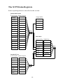
Functional Description of GPIB / 488 Interface …………………..
IEEE 488 Addressing ……………………………………………...
Bus Description …………………………………………………….
Sending Commands Over GPIB Remote Interface ………………..
Serial Poll Procedure ………………………………………………
Interrogative Commands Over GPIB Interface ……………………
56
57
58
59
61
62
62
Commands Sent Over Remote Interface …………………………..
Introduction to SCPI Language ……………………………………
SCPI Commands Overview ……………………………………….
63
64
69
DISPlay Subsystem ………………………………………………..
MEASure Subsystem ……………………………………………….
MEMory Subsystem ………………………………………………...
OUTPut Subsystem …………………………………………………
SOURce Subsystem ………………………………………………..
STATus Subsystem …………………………………………………
SYSTem Subsystem ………………………………………………..
TRIGger Subsystem ………………………………………………..
69
70
71
72
73
80
81
82
Non_SCPI commands ……………………………………………….
IEEE 488.2 commands ……………………………………………...
IEEE 488 Bus Commands ………………………………………….
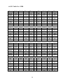
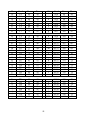
ASCII Table for GPIB ………………………………………………
86
87
89
91
SCPI Status Registers ………………………………………………..
93
Error Messages ……………………………………………………
Command Errors ……………………………………………………
Execution Errors ……………………………………………………
Device Specific Errors ……………………………………………...
Self-test Errors ……………………………………………………..
Calibration Errors ………………………………………………….
97
97
99
99
100
102
2
Table of contents
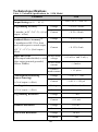
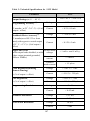
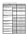
Technical Specifications ……………………………………….…
Supplemental Characteristics ………………………………………
Programming Ranges ……………………………………………….
Reset Va lues ……………………………………… ………………...
Interface Cable ………………………………………………………
105
110
112
113
114
Warranty Information ……………………………………….…
Service Information ………………………………………….…
115
117
3
General Information
Single output programmable DC power supplies.
Output voltage is:
0 to 30.0 V for Model 9120
0 to 20.0 V for Model 9121
0 to 60.0 V for Model 9122
0 to 30.0 V for Model 9123
Output current is:
0 to 3.00 A for Model 9120
0 to 5.00 A for Model 9121
0 to 2.50 A for Model 9122
0 to 5.00 A for Model 9123
The power supply can be locally or remote controlled.
Available interfaces for 912x power supply models:
RS-232
GPIB / 488
9120
Standard
Optional
9121
Standard
Optional
9122
Standard
Optional
9123
Standard
Standard
The commands available in remote interface mode are
•
SCPI (Standard Commands for Programmable Instruments) commands
(1999 SCPI standard)
•
IEEE 488.2 commands
•
IEEE 488 bus commands (only for GPIB / 488 interface)
5
6
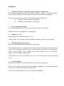
Features
• Constant Voltage / Constant Current modes of operation
This power supply can operate in either constant voltage or constant current
modes. The passing from one mode of operation to another is automatic.
The active mode of operation is indicated using two indicators:
CV – constant voltage mo de of operation
CC – constant current mode of operation
• Overvoltage protection
Overvoltage protection circuit can be locally or remote activated.
When it is active, ovp indicator is displayed.
• Output on / off
When output off, output voltage is 0 V.
This permits a zero output voltage without switching off the power supply.
• 100 operating states storage
States are identified by location number and name.
Stored parameters are: voltage limit, voltage step, overvoltage protection level,
state of overvoltage protection circuit, current limit, current step, voltage trigger
value, current trigger value, trigger delay value, trigger source, stored state
name, state of display, output state.
After power on, state 0, named power_up will become the current operating
state.
• error messages
Errors are stored in a 20 locations FIFO (first in first out) queue.
They can be read in local mode (error number returned) or in remote operation
mode (error number and definition returned).
Every error is announced by a beep and the err indicator.
7
8
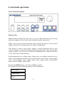
Local mode operation
Front Panel Description
Memory Key
Note: Memory location 00 is the power_up state. When the unit is powered up,
the power supply will set itself to the settings stored in location 00.
Note: If you press the Recall button while turning the power on, the power
supply will power up using memory location 01 parameters.
This button is used to store power supply’s current operating state in nonvolatile memory. Using this function all operating parameters are saved so they
can be recalled. You can store 100 different operating states (numbered from 0
to 99) in the non-volatile memory.
Stored parameters are: voltage limit, voltage step, overvoltage protection level,
state of overvoltage protection circuit, current limit, current step, voltage trigger
value, current trigger value, trigger delay value, trigger source, stored state
name, state of display, output state.
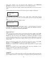
By pressing Memory key, you enter in Memory menu.
By turning the knob following options will be displayed:
Store State
Name State
Exit
9
Options are selected by pressing Memory key when the desired option is
displayed.
Memory Menu Overview
Store State
Store State option will store the current operating state without setting a
name for this state.
By pressing Memory key, state number and state name (if you set one) are
displayed in ascending order by turning the knob.
In this menu, Exit option is available, too. In this case, you leave the store
operation mode, without changing anything. No Change message will be
displayed and the power supply returns to the previous state (the state
before entering Memory menu).
The states are scrolled using the knob.
A location is selected by pressing Memory key. If the location you choose
is already written, it is overwritten (without any warning) with the current
state parameters, but the name (the set one or the default one remains
unchanged). Done message will be displayed.
Name State
Name State option allows you to set a name for selected state (you can also
change a name set before).
The state name can have up to 10 charatcters. The default name is 10 blank
characters.
By pressing Memory key, state number of non-volatile memory locations is
displayed in ascending order by turning the knob.
By pressing Memory key again, state name can be set.
When setting the name, selected digit has the cursor underneath it.
Characters of the name are selected by rotating the knob. When desired
ASCII character is displayed, you can pass to another digit selection using >
< cursor position keys. When the desired name is set, you press Memory
again and the state name is stored in the selected location of the non-volatile
memory. Done message will be displayed.
10
In this menu Exit option is available, too. In this case, you leave the store
operation mode, without changing the name for any state. No Change
message will be displayed and the power supply returns to the previous state
(the state before entering Memory menu).
Important note!
Store State option will store the parameters of current operation state in the
selected location and will not set a name for the stored state.
NameState option will set a name for the selected state.
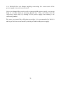
Exit
Exit option allows you to leave the store operation mode, without changing
anything. No Change message will be displayed and the power supply
returns to the previous state (the state before entering Memory menu).
Important note!
If you enter in the Memory menu and no action takes place for approx. 20
seconds, the power supply leaves the Memory menu. No Change message is
displayed and the power supply returns to the previous state (the state before
entering Memory menu).
11
Storing States in Front Panel Mode
To store an operating state in front panel mode you must follow the steps
described bellow:
1. Set the power supply in the desired operating state
Stored parameters are: voltage limit, voltage step, overvoltage protection level,
state of overvoltage protection circuit, current limit, current step, voltage trigger
value, current trigger value, trigger delay value, trigger source, stored state
name, state of display, output state.
Voltage step, current step, voltage trigger value, current trigger value, trigger
delay value, trigger source and state of display parameters can be set only over
the remote interface, using SCPI commands (for more information, please refer
to SCPI Commands section).
The rest of the parameters can be set either from the front panel, or over the
remote interface.
2. Enter the Memory menu
By pressing Memory key, you enter Memory menu.
By turning the knob, following options are displayed:
Store State
Name State
Exit
Options are selected by pressing Memory key when desired option is
displayed.
3. Select StoreState option
When Store State or Name State options are selected, state number and state
name (if available) of non-volatile memory locations are displayed in ascending
order, by turning the knob.
If Store State option is selected, the stored operating state has the default
name, if none set before.
Store State option will store the parameters of current operation state and will
not set a name (or will not change it, if the name was set before) for the stored
state.
12
The saving action is realized by pressing Memory key. After that, Done
message will be displayed and the power supply returns to normal mode.
4. Select Name State option
In order to select this option , Memory key must be pressed again.
NameState option allows you to set a name for the selected state.
The saving action is realized by pressing Memory key. After that, Done
message will be displayed.
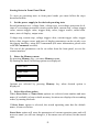
Done
Important note!
The power supply allows 100 states to be stored. When shipped, the power
supply has power_up state stored and all the other locations are empty.
The stored states are kept in a non-volatile memory, so they won’t be lost when
the power supply is turned off.
A state location can be overwritten (both name and parameters) without any
notification from the power supply.
13
Recall Key
This key is used to recall an operating state from the storage locations in nonvolatile memory. You can recall any operating state from 100 different
operating states stored in the non-volatile memory. The recalled state becomes
the current operating state.
By pressing Recall key, you enter in Recall menu.
By turning the knob, following options will be displayed:
00: power_up
01:
02: Test_mode
etc. (all 100 operating states are displayed)
Exit
Reset
Options are selected by pressing Recall key when the desired option is
displayed.
Recalling action is terminated by pressing Recall key. After that, Done
message will be displayed.
Recall Menu Overview
01: State 1
When a state option is selected, the stored state recalled becomes the current
operating state of the power supply.
Recalled parameters are: voltage limit, voltage step, overvoltage protection
level, state of overvoltage protection circuit, current limit, current step,
voltage trigger value, current trigger value, trigger delay value, trigger
source, stored state name, state of display, output state.
14
Exit
Exit option allows you to leave the Recall menu, without changing
anything. No Change message will be displayed and the power supply
returns to the previous state (the state before entering Recall menu).
Reset
Reset option allows you to reset the power supply without switching off
(for more information, please refer to Reset Values section).
00: power_up
After power up, the power supply recalls state 0.
When delivered, power_up state has the following parameters:
Ulim = 1 V
Ilim = maximum available current value (see Programing ranges
table, in the Techincal Specifications section)
OVP trip level = maximum programmable value (see Programing
ranges table, in the Techincal Specifications section)
Output state on
The rest of the parameters have the default value after reset. (please refer to
Reset values table, in the Techincal Specifications section)
For this operating state, Name State option is not available (so the state
name cannot be changed), but Store State option is available (so the user
can save the desired state for power up).
Important note!
If you enter Recall menu and no action takes place for approx. 20 seconds, the
power supply leaves the Recall menu. No Change message is displayed and
the power supply returns to the previous state (the state before entering Recall
menu).
15
Recalling States in Front Panel Mode
To recall an operating state in front panel mode, you must follow the steps
described bellow:
1. Enter the Recall menu
By pressing Recall key, you enter the Recall menu.
By turning the knob, following options are displayed:
01: State 1
02: Test_mode
etc. (all 100 operating states are displayed)
Exit
Reset
2. Select the operating state
By using < > keys (to select the digit you modify by turning the knob) and
turning the knob all operating states stored in non-volatile memory are
displayed. An operating state is recalled by pressing Recall key when desired
state is displayed.
3. Recall the operating state
When Recall key is pressed, the selected operating state becomes the current
operating state of the power supply, after Done message is displayed.
16
Limit Ke y
The power supply works in 2 modes:
Ø Limit mode
Ø Normal mode
In limit mode limit values of voltage and current are displayed. These are the
programmed values (from the front panel or over the remote interface).
Limit key is used to get the power supply to limit mode. In this mode, lmt
indicator and limit values for voltage and current will be displayed.
In limit mode, limit values can be adjusted by turning the knob. To adjust
values in limit mode, > < keys must be used to select the digit you want to
adjust. The selected digit has the cursor underneath it. To increase / decrease
value of digit, knob must be turned.
After setting the limit values, by pressing Limit key, the power supply returns
to normal mode. It also returns to normal mode after several seconds (display
time-out) with no action.
In normal mode, voltage and current values measured at the output terminals of
the power supply are displayed.
When you turn on the power supply, the cursor is placed underneath the voltage
value (units digit). To pass from voltage value to current value Volt/Amp key
must be used. This key toggles between voltage value and current value.
17
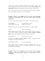
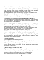
Modes of Operation
Depending on the application, the power supply can be used as a constant
current source or as a constant voltage source.
In order to understand constant current and constant voltage operation, a
numeric example will be used.
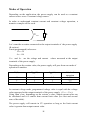
Uout
R
Let’s consider a resistor connected to the output terminals of the power supply
(R resistor).
Limit (programmed) values are:
Ulim =5V
Ilim =2A
Uout and Iout are the voltage and current
terminals of the power supply.
values measured at the output
Depending on the resistor value, the power supply will pass from one mode of
operation to another
R (Ù)
Uout (V)
Iout (A)
10
5
1
5
5
2
0.5
1
2
Mode of
operation
CV
CV
CC
In constant voltage mode, programmed voltage value is equal with the voltage
value measured at the output terminals of the power supply. (Uout = Ulim ).
Using Ohm’s law, depending on the resistor’s value, output current value can
be calculated and it is smaller than current limit value (see first and second
rows of the table).
The power supply will remain in CV operation as long as the limit current
value is greater than output current value.
18
When the resistor’s value decreases so the output current value becomes equal
to the current limit value, power supply will go to constant current operation
(see third row of the table).
If the resistor value is R = 1 Ù, for Uout = 5V, using Ohm’s law the output
current is 5A. But this value is greater than current limit value, so the power
supply limits the output current to the limit programmed value. That is why in
the third row of the table Iout = 2 A. In this case, Uout is changed, too. Using
Ohm’s law again, the output voltage is calculated using output current value
and the resistor value, so it is 2 V.
So the power supply will go to constant current operation when the output
current value becomes equal or greater than the limit value.
When the output current value becomes smaller than the limit value (by
changing resistor’s value), the power supply will go back to constant voltage
operation.
In conclusion:
CV:
Uout = Ulim
and
Iout < Ilim
CC:
Uout < Ulim
and
Iout = Ilim
The following section will explain how to get the power supply in constant
current operation mode and in constant voltage operation mode.
19
Constant Current Operation
In constant current operation, current values in limit mode and normal mode are
the same, but voltage values are not.
To set the power supply in constant current operation, you must follow the
steps described bellow:
1.
Select the limit values for voltage and current parameters (Ulim and
Ilim ), depending on the application
2. Calculate resistor’s value Rload.
Using Ohm’s law, calculate the resistor’s value that allows the power supply to
go in constant current mode of operation.
3. Turn on the power supply and set limit mode operation
Press Limit key to set limit mode.
Now the power supply displays limit values for voltage and current. lmt
indicator is displayed, too. (it will be displayed until you go to normal mode).
4. Set voltage and current limit values
Limit values must be chosen so the following conditions are respected:
Ulim > Ilim · Rload ,so
Ulim < Uout
Ilim < Iout
Voltage and current limit values are set using:
Volt / Amp key to select current value,
> < keys to select the digit to adjust (selected digit has cursor underneath it)
knob to set the digit to desired value
5. Set normal mode operation
You can set normal mode operation by pressing Limit key or let the display
time-out (after several seconds with no action, power supply returns to normal
mode operation).
6. Disable the output of the power supply
By pressing On / Off key, the output of the power supply can be disabled.
7. Connect Rload resistor to the output terminals
Rload resistor is connected between (-) and (+) terminals of the power supply.
20
8. Enable the output of the power supply
By pressing On / Off key, you enable the output.
Power supply goes to normal mode operation and CC indicator will be
displayed. In this case constant current operation is active.
If CV indicator will be displayed, you must set a higher value for voltage limit.
Important note!
By turning the knob, voltage and current limit values can be adjusted.
The adjustion of the voltage limit value can be seen only in limit mode.
The adjustion of the current limit value can be seen in both limit mode and
normal mode.
Impor tant note!
Constant current operation can be used depending on the application.
It is very useful to protect the circuitry connected to the power supply from
accidently increases of current value.
21
Constant Voltage Operation
In constant voltage operation, voltage values in limit mode and normal mode
are the same, but current values are not
To set the power supply in constant voltage operation, you must follow the
steps described bellow:
1.
Select the limit values for voltage and current parameters (Ulim and
Ilim ), depending on the application
2. Calculate resistor’s value Rload.
Using Ohm’s law, calculate the resistor’s value that allows the power supply to
go in constant current mode of operation.
3. Turn on the power supply and set limit mode operation
Press Limit key to set limit mode.
Now the power supply displays limit values for voltage and current. lmt
indicator is displayed, too. (it will be displayed until you go to normal mode).
4. Set voltage and current limit values
Limit values must be chosen so the following conditions are respected:
Ulim < Ilim · Rload ,so
Ulim < Uout
Ilim < Iout
Voltage and current limit values are set using:
Volt / Amp key to select current value,
> < keys to select the digit to adjust (selected digit has cursor underneath it)
knob to set the digit to desired value
5. Set normal mode operation
You can set normal mode operation by pressing Limit key or let the display
time-out (after several seconds with no action, power supply returns to normal
mode operation).
6. Disable the output of the power supply
By pressing On / Off key, the output of the power supply can be disabled.
7. Connect Rload resistor to the output terminals
Rload resistor is connected between (-) and (+) terminals of the power supply.
22
8. Enable the output of the power supply
By pressing On / Off key, you enable the output.
Power supply goes to normal mode operation and CV indicator will be
displayed. In this case constant voltage operation is active.
If CC indicator will be displayed, you must set a higher value for current limit.
Important note!
By turning the knob, voltage and current limit values can be adjusted.
The adjustion of the current limit value can be seen only in limit mode.
The adjustion of the voltage limit value can be seen in both limit mode and
normal mode.
23
On / Off Ke y
On / Off key is used to enable / disable the output of the power supply from the
front panel. By pressing On / Off key, you alternate these two states: output on
/ output off.
When the output is off, power supply displays:
Output off
The indicators according to power supply’s state will also be displayed (e.g.:
ovp, err indicators).
When output off, output voltage is 0 V. So this command permits a zero output
voltage without switching off the power supply.
When output off, knob is disabled, to prevent the unwanted changes in voltage
and current values. The keys from the front panel are not disabled. You can
also go to limit mode and set limit values for voltage and current. In this case
both lmt and off indicators will be displayed.
When output off, by pressing On / Off key, the output is enabled. The power
supply will go to normal mode of operation (voltage and current measured
values are displayed) or to limit mode of operation (voltage and current limit
values are displayed), depending on the state the power supply was before
disabling the output.
The output state of the power supply is one of the parameters stored in nonvolatile memory for each state .
24
Remote / Local Key
This key has a double function, depending on the state of the power supply
(remote mode or local mode).
Local Mode Function
While in local mode of operation, Remote / Local key has a double function,
depending on the state of the power supply.
If the power supply is in calibrating mode, Remote / Local key is used to leave
the calibrating mode and return to normal mode of operation (for more
information, please refer to Calibration Overview section)
If the power supply is in limit mode or normal mode of operation, by pressing
Remote / Local key, available interfaces are displayed.
Remote Interface Configuration
Available interfaces for 912x power-supply models:
RS-232
GPIB / 488
9120
Standard
Optional
9121
Standard
Optional
9122
Standard
Optional
9123
Standard
Standard
If a power supply has both interfaces implemented, only one interface can be
enabled at a time.
Interface selection (and coresponding parameters) is kept in a non-volatile
memory, so when powered on, the last selected interface is active.
For a power supply that has both interfaces implemented, when delivered GPIB
/ 488 interface is selected.
The remote interface can be selected by using front panel or by using a
command sent over the interface. Here is described remote interface selection
using front panel keys.
If the power supply is in local mode of operation, by pressing Remote / Local
key, selected interface is displayed (RS-232 or GPIB / 488).
25
By turning the knob, following options will be displayed:
RS - 232
GPIB / 488
By pressing Remote / Local key once again, the displayed interface is selected
and the specific parameters can be set (for RS – 232 interface, baud rate and
parity will be set, for GPIB interface GPIB address of the power supply will be
set).
The parameter values can be changed by turning the knob. When desired value
for the parameter is displayed, Remote / Local key must be pressed.
Important note!
If you enter Remote / Local submenu and no action takes place for approx. 20
seconds, the power supply will leave this submenu. No Change message is
displayed and the power supply returns to the previous state (the state before
entering this submenu).
Important note!
If you enter Remote / Local submenu and no action takes place for approx. 20
seconds, the power supply will leave this submenu. No Change message is
displayed and the power supply returns to the previous state (the state before
entering this submenu).
Important note!
While in local mode, if by pressing Remote / Local key
I / O Error
message will be displayed, it means that the remote interface parameters cannot
be read from the non-volatile memory. The power supply must be turned off
and then turned on.
If this message is displayed again after pressing Remote / Local key in local
mode, the power supply must be delivered to B&K Precision for service.
26
RS-232 Configuration
Available settings for RS-232 interface:
♦ Baud rate: 1200, 2400, 4800, 9600 (factory setting: 9600)
♦ Parity and data bits: None – 8 data bits (factory setting)
Odd – 7 data bits
Even – 7 data bits
♦ Number of start bits: 1 bit (cannot be changed)
♦ Number of stop bits: 1 bit (cannot be changed)
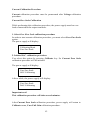
Set RS – 232 remote interface parameters
1. Select RS – 232 interface
Press Remote / Local key. If “GPIB / 488” is displayed, turn the knob until
“RS-232” will be displayed.
RS - 232
Press Remote / Local key again. Baud rate settings will be displayed.
2. Select baud rate
By turning the knob, you will view available baud rates: 1200, 2400, 4800,
9600 bits per second.
When desired baud rate is displayed, press Remote / Local key. Parity settings
will be displayed.
3. Select parity
By turning the knob, available parities will be displayed:. Even, odd or no
parity. Select the desired parity.
By pressing Remote / Local key, the settings will be saved in the non-volatile
memory and Saved message will be displayed.
If you didn’t change any of the previous set parameters, the power supply will
display No Change message.
If you did change a single parameter from the previous set parameters, Saved
message will be displayed.
After one of these messages is displayed for several seconds, the power supply
returns to the previous state.
27
GPIB / 488 Configuration
Available setting for GPIB / 488 interface is address of the power supply.
An IEEE 488 address can take values from 0 to 30.
GPIB address is kept in a non-volatile memory, so when powered on, the last
selected address is active.
When supplied from the factory, power supply’s GPIB address is 5.
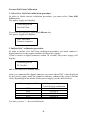
Set GPIB remote interface parameters
1. Select GPIB / 488 interface
Press Remote / Local key. If “RS-232” is displayed, turn the knob until
“GPIB / 488” will be displayed.
GPIB / 488
Press Remote / Local key again. GPIB address will be displayed.
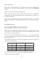
2. Select GPIB address
By turning the knob, GPIB address can be selected.
ADDR 05
When desired GPIB address is displayed, press Remote / Local key. By
pressing Remote / Local key, the settings will be saved in the non-volatile
memory and Saved message will be displayed.
If you didn’t change any of the previous set parameters, the power supply will
display No Change message.
If you did change a single parameter from the previous set parameters, Saved
message will be displayed.
After one of these messages is displayed for several seconds, the power supply
returns to the previous state.
28
Remote Mode and Indicators
When RS-232 interface is selected, SYSTem:REMote command must be the
first sent command. Otherwise, if another command is sent first, Power supply
in local mode message will be sent to PC.
While in remote interface mode of operation (after sending SYSTem:REMote
command), rmt indicator will be displayed. In this case, all front panel keys are
disabled, except Remote / Local key, which is active. This key allows you to
put the power supply in local mode of operation, so all front panel keys become
active.
In order to control the power supply using remote commands again,
SYSTem:REMote command must be sent again, before any other commmand.
When GPIB interface is selected, adr indicator is displayed when the power
supply is addressed (either as a Listener or as a Talker) or when a GPIB
command is sent over the interface.
When SYSTem:REMote command is sent over the GPIB interface, an error will
be generated: Err 501, Command allowed only in RS-232.
29
Errors / Calibrate Key
This key has a double function: errors related in normal mode (see this section)
and calibration related in calibration mode (see calibration section).
There are 2 types of errors: user defined errors and errors defined by SCPI 1999
standard.
Every time an error is generated, a beep will be generated by the power supply
and err indicator will be displayed.
Generated errors are saved in an error queue, in FIFO (first in – first out) order.
If more than 20 errors are generated, the last error is overwritten with –350
error (queue overflow error) and no more errors are saved.
While in remote mode (rmt indicator is displayed), errors are erased from the
queue as you read them.
By pressing Errors / Calibrate key, you enter Errors / Calibrate menu. By
turning the knob, following options are displayed:
Errors
Cal String
Exit
Options are selected by pressing Errors / Calibrate key when the desired
option is displayed.
Errors
Errors option allows you to view the generated errors.
If you press Errors / Calibrate key again, by turning the knob you can see
all generated errors. Error’s code will be displayed. When all errors were
viewed, if continue to turn the knob, they will be displayed again.
After you viewed all errors, you press Errors / Calibrate key again. The
power supply will erase all the errors from the error queue and Errors
Erased message will be displayed.
30
After several seconds the power supply will go back to normal mode. The
err indicator will not be displayed anymore.
If there are no errors in the queue and you select Errors option in order to
view the errors, the power supply will display:
No Errors
And then it will return to normal mode.
There are 3 ways of erasing the error queue:
♦ By turning off and then turning on the power supply
♦ By pressing Errors / Calibrate key after errors are displayed, in local
mode
♦ By reading errors, in remote operation.
Important note!
If you let the display time out while viewing errors locally, the power
supply will go back to normal mode, without erasing the error queue.
Cal String
The power supply allows you to store a calibration message. It may contain
last calibration date, the date when the next calibration must be done or the
name and the phone number of the person to contact for a new calibration.
This message can have up to 40 characters. It can be set only remote
interface and it is saved in non-volatile memory.
When delivered, the power supply has the following calibration string set:
“CALIBRATION
DATE:
MMM/DD/YYYY”
(for
example:
CALIBRATION DATE: Feb/11/2005)
Cal String option allows you to view the calibration string.
If you press Errors / Calibrate key when Cal String option is displayed,
the calibration message will be displayed. To increase the scrolling speed,
you must press > key. To decrease scrolling speed, you must press < key.
31
After the first scrolling of the calibration message, < or > keys must be
pressed in order to scroll the message again.
Exit
Exit option allows you to leave this menu, without changing anything.
Exiting message will be displayed and the power supply returns to the
previous state (the state before entering this menu).
Important note!
If you enter in the Errors / Calibrate menu and no action takes place for
approx. 20 seconds, the power supply leaves this menu. Exiting message is
displayed and the power supply returns to the previous state (the state before
entering Errors / Calibrate menu).
32
Calibration Overview
Calibration is a procedure that ensures that the power supply will work
properly, with parameters specified within Technical Specification section.
Before initiating the calibration procedure, the following conditions must be
assured:
§ disconnect any loads connected to the power supply and turn it on
§ let the power supply turned on for 1 hour, with no loads connected before
you start the calibration procedure
§ calibration ambient temperature must be 25 0 C
§ ambient relative humidity must be less then 80%.
Recommended calibration interval is 1 year.
Important note!
In order to perform the calibration procedure, a digital multimeter is needed. It
must have the following characteristics:
Voltage resolution: 0.1 mV
Current resolution: 0.01 mA
Acurracy: 0.01 %
Calibration Security Code
To prevent accidental or unauthorized calibration procedures, the power supply
has a calibration security code. This security code is optional, so you may have
it or not. The power supply will work properly in both cases.
Security code may contain numbers (0..9), small letters (a..z) and spaces (“ “).
Any of these characters may be used as the first character in security code.
Security code may contain up to 11 characters. But it is not necessary for you to
use all 11 characters for the security code.
The security code is saved in non-volatile memory and it doesn’t change when
you turn on or turn off the power supply.
When delivered, power supply has the following security code: 0000
In order to initiate the calibration procedure, first you must unsecure the power
supply (if a security code is set).
33
Unsecure Procedure for Calibration
To unsecure the power supply, the next steps bust be followed:
1. Turn on the power supply in calibrating mode
To enter calibrating mode, you must turn on the power supply while pressing
Errors / Calibrate key. You release the key after the long beep. After that, the
power supply will display:
Calibrating Mode
Secured
if the power supply is secured (if the power supply has a security code set). If
this message is displayed, go to step 2.
or :
Calibrating Mode
Unsecured
if the power supply is not secured (if the power supply has been turned off after
the unsecure procedure).
If the power supply is already unsecured, you can proceed with calibration (see
Calibration procedure section)
2. Enter security code
Press OVP / Secure key. The power supply will display:
Security code:
___________
Here you must enter the security code, using > < keys and knob. The selected
digit has the cursor underneath it. If you set the digit to the desired value, you
must press > key and go to the next digit, if you want.
After you entered the security code, press OVP / Secure key and if the security
code is correct, the power supply will display:
Calibrating Mode
Unsecured
34
From this moment you can proceed with calibration (see Calibration
procedure section) or you can go back to normal mode operation.
From now on, the power supply remains unsecured until you set a new secure
code.
If the security code you entered is not correct, power supply will display:
Security code:
invalid
for 1 second. 703 error (Invalid secure code) and a short beep will be
generated. You can see the error in normal mode operation (by pressing Local
key).
After that power supply will display again:
Security code:
___________
and you must enter security code again, using < > keys and knob. If you don’t
remember the correct security code, you may follow the hardware unsecure
procedure (see Hardware unsecure procedure).
Important Note!
While in calibrating mode, before you unsecure the power supply, only Local,
< > and Secure keys are active (all the rest are locked). The knob is also active.
Local key can be used at any moment of unsecure procedure to leave
calibrating mode and go back to normal mode operation. Secure key is used in
unsecure procedure of the power supply (allows you to enter and validate the
secure code).
While in calibrating mode, after you unsecure the power supply, only Local,
Secure, < > and Calibrate keys are active. The knob is also active.
Local key is used to leave calibrating mode and go back to normal mode
operation.
Secure key is used to set a new security code (you may introduce a new
security code and secure again the power supply).
Calibrate key is used to proceed with calibration.
Attention!
Local key is active all the time while in calibrating mode and by pressing it the
power supply returns to normal mode. Leaving the unsecure procedure (before
35
it is finished) does not change anything concerning the secure state of the
power supply (secured or unsecured).
After you changed the security code or unsecured the power supply, you can go
back to normal mode by pressing Local key. (You can come back to
calibrating mode only by turning off the power supply and starting it in
calibrating mode).
But once you started the calibration procedure, it is recommended to finish it
and to go back to normal mode by turning off and on the power supply.
36
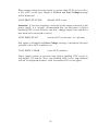
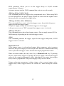
Hardware Unsecure Procedure for Calibration
This procedure may be used to unsecure the power supply if you forgot the
security code.
To unsecure the power supply without using the security code, follow the next
steps:
1.
2.
Turn off the power supply. Disconnect the power cord and all loads
connected to the power supply.
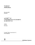
Remove power supply’s cover. Set J6 jumper for hardware unsecuring
mode.
J5
J6
J5
J6
Normal
Hardware
unsecuring unsecuring
3.
4.
Connect the power cord to the power supply. Turn on the power supply in
calibrating mode.
Unsecure the power supply.
To unsecure the power supply you must press Secure key. Power supply will
display:
Calibrating Mode
Secured
Press again Secure key the power supply will display:
Security code:
__________
Here any security code may be introduced, since it is not verified by the power
supply.
Press again Secure key and you will unsecure the power supply. It will display:
Calibrating Mode
Unsecured
37
The power supply remains unsecured until you enter a new security code.
Important note!
Even if you are in calibrating mode, you cannot set a security code as long as
the J6 jumper is in hardware unsecuring position.
5.
Set J6 jumper for normal unsecuring mode.
Important note!
If you turn on the power supply in either normal mode or calibrating mode and
J6 jumper is in hardware unsecuring position, error 701 (Calibration security
disabled by jumper) will be generated.
6.
Turn off the power supply and reassemble it.
38
Calibration Procedure
Before initiating the calibration procedure, the following conditions must be
assured:
§ disconnect any loads connected to the power supply and turn it on
§ let the power supply turned on for 1 hour, with no loads connected before
you start the calibration procedure
§ calibration ambient temperature must be 25 0 C
§ ambient relative humidity must be less then 80%.
On calibration procedure there are three parameters that must be calibrated:
voltage, OVP and current.
You can leave the calibration procedure at any time by turning off the power
supply or by pressing Local key.
But once you started the calibration procedure, it is recommended to finish it
and to go back to normal mode by turning off and then turning on the power
supply.
In order to be sure that the power supply will work properly in normal mode
after you leave the calibration procedure, you must turn off the power supply.
Recommended calibration interval is 1 year.
Before calibrating the power supply you must unsecure it, if secured (see
Calibration Overviewsection).
After you unsecured the power supply and you pressed Calibrate key, you go
to Calibrate menu. By turning the knob next options are available:
1. Volt Zero Scale
2. Volt Full Gain
3. OVP
4. Curr Zero Scale
5. Curr Full Gain
Options are selected by pressing Calibrate key.
Important note!
In order to perform a correct calibration, the calibration procedures from the
Calibrate menu must be followed in the order they are displayed by the power
supply.
39
Voltage Calibration Procedure
After you unsecured the power supply and you pressed Calibrate key, you
entered calibrate mode.
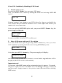
Volt Zero Scale Calibration
1. Select Volt Zero Scale calibration procedure
In order to start voltage calibration procedure, you must select Volt Zero Scale
option.
The power supply will display:
Calibrating Mode
Volt Zero Scale
You select this option by pressing Calibrate key.
The power supply will display:
Volt Zero Scale
DAC:1999
2. Initiate DAC calibration procedure
Connect a digital voltmeter to the output terminals of the power supply. After
that, you must adjust DAC value displayed by the power supply until the
voltmeter indicates the closest possible to 0.000 V value.
For this, you use > < keys and the knob.
It is not necessary to disconnect the digital voltmeter, since you will need it
later on calibration procedure!
3. Initiate ADC calibration procedure
Press Calibrate key. This will initiate ADC calibration procedure. The power
supply will display:
Volt Zero Scale
ADC Calibrating
After ADC calibration, power supply will return to Calibrate menu Volt Full
Gain calibration procedure.
40
Volt Full Gain Calibration
1. Select Volt Full Gain calibration procedure
In order to finish voltage calibration procedure, you must select Volt Full Gain
option.
The power supply will display:
Calibrating Mode
Volt Full Gain
You select this option by pressing Calibrate key.
The power supply will display:
Volt Full Gain
DAC:31470
2. Initiate DAC calibration procedure
Connect a digital voltmeter to the output terminals of the power supply. After
that, you must adjust DAC value displayed by the power supply until the
voltmeter indicates the correct voltage value, depending on the model of the
power supply (see the table bellow).
Power supply model
9120
9121
9122
9123
Voltage value for
Volt Full Gain calibration
16.3840 V
16.3840 V
32.7700 V
16.3840 V
For this, you use > < keys and the knob
3. Initiate ADC calibration procedure
Press Calibrate key. This will initiate ADC calibration procedure. The power
supply will display:
Volt Full Gain
ADC Calibrating
After ADC calibration, power supply will return to Calibrate menu, OVP
calibration procedure.
41
OVP Calibration
While performing this calibration procedure, the power supply must have no
loads connected to the output terminals.
1. Select OVP calibration procedure
In order to initiate OVP calibration procedure, you must select OVP option.
The power supply will display:
Calibrating Mode
OVP
You select this option by pressing Calibrate key.
The power supply will display:
Calibrating OVP
Please wait…
Important note!
This calibration procedure will take several minutes.
After OVP calibration, power supply will return to Calibrate menu, Current
calibration procedure.
42
Current Calibration Procedure
Current calibration procedure must be permormed after Voltage calibration
procedure.
Current Zero Scale Calibration
While performing this calibration procedure, the power supply must have no
loads connected to the output terminals.
1. Select Curr Zero Scale calibration procedure
In order to start current calibration procedure, you must select Curr Zero Scale
option.
The power supply will display:
Calibrating Mode
Curr Zero Scale
2. Initiate DAC calibration procedure
You select this option by pressing Calibrate key. So Current Zero Scale
calibration procedure will be initiated.
The power supply will display:
Curr Zero Scale
ADC:Calibrating
After a while, the power supply will display:
Curr Zero Scale
DAC:Calibrating
Important note!
This calibration procedure will take several minutes.
After Current Zero Scale calibration procedure, power supply will return to
Calibrate menu, Curr Full Gain calibration procedure.
43
Current Full Gain Calibration
1. Select Curr Full Gain calibration procedure
In order to finish current calibration procedure, you must select Curr Full
Gain option.
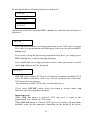
The power supply will display:
Calibrating Mode
Curr Full Gain
You select this option by pressing Calibrate key.
The power supply will display:
Curr Full Gain
Connect Ammeter
2. Initiate DAC calibration procedure
In order to initiate Curr Full Gain calibration procedure, you must connect a
digital ammeter to the output terminals of the power supply.
If don’t connect a digital ammeter within 30 seconds, the power supply will
display:
Calibrating Mode
CC Not Set
and it will return to Calibrate menu.
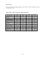
After you connected the digital ammeter, you must adjust DAC value displayed
by the power supply until the ammeter indicates indicates the correct current
value, depending on the model of the power supply (see the table bellow).
Power supply model
9120
9121
9122
9123
Current value for
Curr Full Gain calibration
2.62144 A
2.62144 A
1.31072 A
2.62144 A
For this, you use > < keys and the knob
44
3. Initiate ADC calibration procedure
Press Calibrate key. This will initiate ADC calibration procedure. The power
supply will display:
Curr Full Gain
ADC Calibrating
After ADC calibration, power supply will return to Calibrate menu.
In this moment, the calibration procedure is finished. By presing Local key, the
power supply will return to local mode.
Important note!
In order to be sure that the power supply will work properly in normal mode
after you leave the calibration procedure, you must turn off the power supply.
45
OVP / Secure Key
This key has a double function: OVP settings in normal mode operation and
secure key in calibration mode operation (for the latter see Calibration
section).
In this section OVP functions will be described.
OVP circuit prevents the output voltage from rising above a programmed
voltage value. So the load connected to the output terminals is protected of
overvoltage situations.
Overvoltage protection circuit is activated when output voltage value becomes
equal or greater than the programmed trip level for overvoltage protection
circuit.
OVP Menu Overview
By pressing OVP / Secure key, you enter OVP menu.
Here, programmed OVP trip level will be displayed.
When you turn on the power supply, OVP trip level is OVP trip level value
saved at power_up state (state 0). This value can be changed by the user (and
saved in power_up state if wanted).
Here you can set desired OVP trip level, by using > < keys to select the digit
you want to adjust (selected digit has the cursor underneath) and knob to set the
digit to desired value.
The programming range for OVP trip level depends on the model of the power
supply (see the table bellow):
Power supply
model
9120
9121
9122
9123
OVP min value
1
1
1
1
V
V
V
V
OVP max value
33 V
22 V
63 V
33 V
The OVP trip level you set is saved by pressing OVP / Secure key.
After that, you enter the OVP menu.
46
By turning the knob, following options are displayed:
OVP On
OVP Clear
OVP Off
Options are selected by pressing OVP / Secure key when the desired option is
displayed.
OVP On
OVP On option enables overvoltage protection circuit. OVP trip level is the
level value you programmed on Level option (after you first pressed OVP /
Secure key).
If you want to keep the previously programmed trip level, you simply press
OVP / Secure key, without changing anything.
If you enable the overvoltage protection circuit, when you return to normal
mode, ovp indicator will be displayed.
OVP Off
OVP Off option makes OVP trip level equal to maximum availabale OVP
value, no matter what what value is set in OVP menu (but the value from
OVP menu does not change).
For maximum available OVP value, see the table above.
If you select OVP Off option, when you return to normal mode, ovp
indicator will not be displayed anymore.
Important note!
When OVP On option is selected, OVP trip level is equal to the
programmed level, shown in OVP menu.
When OVP Off option is selected, OVP trip level is equal to the maximum
available value for this parameter, depending on the mo del of the power
47
supply (see the table above). In this case, the programmed OVP trip level,
shown in OVP menu does not change!
OVP Clear
OVP Clear option is used to clear to OVP condition (for more information
about how you get back to normal mode after OVP level was tripped, please
refer to the next section).
After you select the desired option, a message will be displayed.
If you didn’t change anything of the previous set parameters, the power
supply will display No Change message.
If you did change a single parameter from the previous set parameters Done
message will be displayed.
After one of these messages is displayed for several seconds, power supply
returns to normal mode.
Important note!
If you enter in the OVP menu and no action takes place for approx. 20 seconds,
the power supply will leave the OVP menu. No Change message is displayed
and the power supply returns to the previous state (the state before entering
OVP menu).
If the output voltage value becomes equal or greater than OVP programmed
level and the overvoltage protection circuit is enabled, the power supply will
display:
Over Voltage
Output Off
And the output voltage value will be 0 V (output is disabled).
There are three ways of clearing the OVP condition:
Ø By increasing OVP trip level and clearing the OVP condition
Ø By decreasing the output voltage and clearing the OVP condition
Ø By disabling OVP circuit and clearing the OVP condition
Important note!
When you turn on the power supply, the overvoltage protection circuit is
enabled and the OVP trip level is equal to the one saved in power_up state
(factory setting: maximum available value).
48
Programming OVP Circuit in Front Panel Mode
If you want to program an OVP trip level and to enable the overvoltage
protection circuit using front panel keys, follow the next steps:
1. Turn on the power supply
When you turn on the power supply, the overvoltage protection circuit is
enabled and OVP trip level is set to maximum available value for OVP
parameter, depending on the model of the power supply (see table in the
prevous section).
2. Enter the OVP menu and set OVP trip level
By pressing OVP / Secure key, you enter the OVP menu. The power supply
will display the programmed OVP trip level.
For changing this value, you can use > < to select the digit you want to adjust
(selected digit has the cursor underneath) and then turn the knob to set the
desired value.
After you set the desired value for OVP trip level, you press OVP / Secure key.
Important note!
You cannot set an OVP trip level lower than 1 Volt.
The maximum OVP trip level value depends on the model of the power supply
(see table in the previous section )
3. Enable the OVP circuit
After you set the desired OVP trip level and you pressed OVP / Secure key,
OVP On, OVP Off and OVP Clear options are available.
To enable the OVP circuit, you select OVP On option by turning the knob
OVP On
4. Exit the OVP submenu
To exit the OVP submenu and to validate all the settings you have done, then
you press OVP / Secure key.
After that, Changed message will be displayed and the power supply return to
previous state (the state before you entered the OVP submenu), in normal mode
operation.
ovp indicator will be displayed. If you didn’t change anything, the power
supply will display No Change message.
49
Clearing Overvoltage Condition
There are three ways of clearing the OVP condition:
Ø By increasing OVP trip level and clearing the OVP condition
Ø By decreasing the output voltage and clearing the OVP condition
Ø By disabling OVP circuit and clearing the OVP condition
Attention!
The latter solution disables the OVP circuit, but the first and the second don’t!
In this section we will describe the steps you must follow to clear the OVP
condition in all three cases.
If the output voltage value becomes equal or greater than OVP programmed
level and the overvoltage protection circuit is enabled, the power supply will
display:
Over Voltage
Output Off
And the output voltage value will be 0 V (output is disabled).
50
Clear OVP Condition by Increasing OVP Trip Level
1. Enter the OVP menu
By pressing OVP / Secure key, you enter the OVP menu.
2. Adjust OVP trip level
When you enter OVP menu, OVP trip level is displayed.
Here, you set OVP trip level to a level higher than the programmed voltage
value (Ulim ).
3. Clear OVP condition
After you set the OVP trip level, you press OVP / Secure key.
Here, OVP On, OVP Off, OVP Clear options are available. Select OVP
Clear option by turning the knob.
OVP Clear
After that, press OVP / Secure key. The power supply will display:
Clear OVP:Done
and after several seconds it will return to normal mode. ovp indicator will be
displayed (the OVP circuit is still enabled).
Important note!
If you enter the OVP menu and no action takes place for approx. 20 seconds,
the power supply will leave the OVP menu. No Change message is displayed
and the power supply returns to the previous state (the state before entering
OVP menu).
51
Clear OVP Condition by Decreasing the Output Voltage
1. Decrease the output voltage level bellow OVP trip level
Press Limit key and enter limit mode. Limit values of voltage and current will
be displayed. ovp and lmt indicators will also be displayed.
Adjust for output voltage limit to a lower value than the OVP trip level.
Press Limit key to exit limit mode.
2. Enter OVP menu and clear OVP condition
Here you check that the OVP trip level is greater than the output voltage limit
you set. If it isn’t, go to step 1.
Don’t adjust OVP trip level!
Clear OVP condition by turning the knob and selecting OVP Clear option:
OVP Clear
After that, press OVP / Secure key. The power supply will display:
Clear OVP:Done
and after several seconds it will return to normal mode. ovp indicator will be
displayed (the OVP circuit is still enabled).
Important note!
If you enter OVP menu and no action takes place for approx. 20 seconds, the
power supply will leave the OVP menu. No Change message is displayed and
the power supply returns to the previous state (the state before entering OVP
menu).
52
Clear OVP Condition by Disabling OVP Circuit
1. Disable OVP circuit
By pressing OVP / Secure key, you enter OVP menu.
Here you disable OVP circuit by turning the knob and selecting OVP Off
option.
OVP Off
It doesn’t matter if you change or not OVP trip level as long as you disable the
OVP circuit. But you must be careful to set it to the right value before you
enable OVP circuit next time.
After you selected OVP Off option and you pressed OVP / Secure key, the
power supply will display
Over Voltage
Output Off
because you didn’t clear the OVP condition yet
2. Enter OVP menu and clear OVP condition
You enter OVP menu again by pressing OVP / Secure key. Now you clear
OVP condition by turning the knob and selecting OVP Clear option:
OVP Clear
After that, press OVP / Secure key. The power supply will display:
Clear OVP:Done
and after several seconds it will return to normal mode. ovp indicator will be
displayed (the OVP circuit is still enabled).
Important note!
If you enter in the OVP menu and no action takes place for approx. 23 seconds,
the power supply will leave the OVP menu. No Change message is displayed
and the power supply returns to the previous state (the state before entering
OVP menu).
53
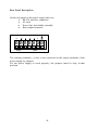
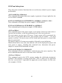
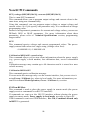
Rear Panel Description
On the rear panel of the power supply there are:
§ RS-232 interface connector
§ AC inlet
§ Power-line fuse-holder assembly
§ Rear output terminals.
+s
+
-
-s
The sensing terminals (+s and -s) are connected to the output terminals of the
power supply by jumpers.
For the power supply to work properly, the jumpers must be kept in that
position.
54
Remote Interface
For remote communication, there are two available interfaces: GPIB / 488
interface and RS-232 interface. The selected interface and the coresponding
settings are saved in a non-volatile memory and does not change after the
power supply is turned off or after a *RST command.
Only one interface can be active at a time.
When the power supply is delivered, GPIB / 488 interface is selected.
RS-232 Interface
In order to connect the power supply to the RS-232 interface, the male DB-9
connector from the rear panel must be used. For all communication sessions
over RS-232 interface, the power supply usses two handshake lines: DTR (Data
Terminal Ready, pin 4) and DSR (Data Set Ready, pin 6).
For more information about the DB-9 connectorand about the connection to a
computer terminal, please refer to Interface Cable section.
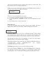
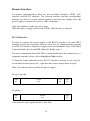
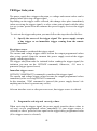
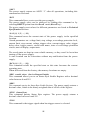
A character frame transmitted over RS-232 interface consists of one start bit,
seven data bits and a parity bit / eight data bits and no parity and a stop bit.
Here is the frame format used by the power supply:
Parity even/odd:
Start
bit
Parity
7 Data
bits
bit
Stop
bit
No parity:
Start
bit
8 Data
bits
Stop
bit
After start bit, least significant bit is sent first.
55
GPIB / 488 Interface
GPIB / 488 interface availability for different models:
RS-232
GPIB / 488
9120
Standard
Optional
9121
Standard
Optional
9122
Standard
Optional
9123
Standard
Standard
GPIB (General Purpose Interface Bus) interface is also known as IEEE 488.
The original 488.1 specification defines the mechanical and electrical
characteristics of the interface and its fundamental protocols.
The 488.2 specification defines a minimum configuration, and adds
specifications for a basic set of instrument commands and common data
formats.
In order to communicate with the power supply over GPIB interface, a
GPIB interface card must be placed in the computer.
A GPIB system allows interconnection of instruments and other devices to a
controlling computer.
Here are some specifications of IEEE 488.1:
§ Up to 15 devices may be interconnected in a GPIB network
§ Configuration of the bus network may be linear or bus
§ 24 bus lines: 8 data lines, 8 control and management lines, 8 GND
lines
§ Data transfer mode: 8-bit parallel
§ Handshake: '3 wire handshake'; reception of each data byte is
acknowledged.
§ total transmission path length: 20m, or L < 2N
L – total transmission path length
N – nu mber of devices
§ Maximum transmission rate: 1 megabyte per second. The actual
data rate is determined by the slowest device.
§ Each device connected to the interface must have a unique address
between 0 to 30 (decimal value).
56
Functional Description of GPIB Interface
Devices from the interface are classified into 3 types:
Listener: a device capable of receiving data over the interface when addressed
to listen by the Active Controller.
There can be up to 14 Listeners on the bus at one time.
Usually the Active Controller will be the Talker, while a single device is the
Listener.
But it is also possible that multiple Listeners will be assigned. In this case, all
of them will execute the received commands.
A device becomes a Listener when it is addressed to listen (when it receives its
Listen address).
It stops being a Listener only when:
§ UNL command is received
§ Interface Clear (IFC) command is sent over the interface.
Talker: a device capable of transmitting data over the interface when addressed
to talk by the Active Controller.
There can be only one Talker on the bus at one time.
Usually, when a device is addressed to talk, it becomes the Talker over the
interface and Active Controller becomes a Listener.
A device becomes a Talker when it is addressed to talk (when it receives its
Talk address).
It stops being a Talker only when:
§ UNT command is received
§ A new Talker is assigned (since there can be only one addressed
Talker on the bus at one time )
§ Interface Clear (IFC) command is sent over the interface
Controller: a device capable of specifying the Talker and the Listeners for a
data or command transfer.
In multiple controller systems, active control may be passed between
controllers. There can be only one addressed Controller on the bus at one time.
The Controller function is usually handled by a computer.
The power supply can only be a Listener or a Talker (when addressed to talk).
57
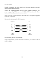
IEEE 488 Addressing
An IEEE 488 address can take values from 0 to 30.
When supplied from the factory, power supply’s GPIB address is 5.
An IEEE 488 device has a Listen address and a Talk address. Listen address
and Talk address bytes are different.
Listen address is defined by adding decimal value of 32 to the address.
Talk address is defined by adding decimal value of 64 to the address.
Decimal value of 31 is a special address value. Listen address byte has the
value of 63 decimal (31 + 32 = 63 decimal). This is a special address byte,
called Unlisten (UNL). This address byte is sent by the Controller before
assigning new Listeners. It tells to the currently assigned Listeners to stop
listening.
For decimal value of 31, Talker address byte has the value of 95 (31 + 64 =
95). This is a special address byte, called Untalk (UNT). This address byte is
sent by the Controller and it tells to the currently addressed Talker to stop being
a Talker, because a new Talker will be assingned.
This power supply has no secondary address implemented.
58
Bus Description
The interface signal lines are organized into three functional groups:
Data lines (8 lines)
Handshake lines (3 lines)
General bus management lines (5 lines)
The bus signal lines use low true logic protocol.
Data lines:
allow transfer of one byte at a time.
Bytes are transferred over the interface in a byte-serial, bit-parallel
manner.
DIO1 represents least significant bit of the byte, while DIO8 represent
most significant bit of the byte transffered over the interface.
Handshake lines:
control byte transfer between devices, using 3-wire handshaking.
the speed of the data transfer is given by the slowest listener, so every
listener can read bytes transferred over the interface correctly.
reception of each data byte is acknowledged.
DAV (Data Valid)
this line is controlled by the Talker
the talker sets DAV line true (active low) when all devices from bus
release NRFD line (NRFD line high).
DAV line true means that data byte is stable on the bus (so it can be
read by the listeners).
NRFD (Not Ready For Data)
this line is controlled by the Listeners to indicate to the Talker if they
are ready to receive new data.
NRFD line will not go high until all Listeners release the line.
NDAC (Not Data Accepted)
this line is controlled by the Listeners to indicate to the Talker if data
was read from the bus
when NDAC line false (high), addressed Listeners indicate that they
read the data from the bus
NDAC line will not go high until all Listeners release the line.
59
General bus management lines:
-
ATN, IFC, REN, SRQ, EOI and they are used by the Active
Controller or System Controller to manage GPIB interface
SRQ (Service Request):
This line is used by any device from the bus.
when is set true (low), the device notifies the Controller that it needs
servicing a request.
Controller will perform a Serial Poll or a Parallel Poll in order to
determine which device requested a service and why.
IFC (Interface Clear):
This line is used only by the Controller.
When IFC line is true (low) all devices from the bus reset the GPIB
interface (Talker and Listeners are unaddressed, service request idle
and Serial Poll disabled).
REN (Remote Enable):
This line is used only by the Controller.
When REN line is set true (low), the bus is in remote mode, so devices
can be addressed to listen or to talk.
A device will go into remote mode only when addressed to listen.
While in remote mode, the device ignores its local front panel controls
(only Remote / Local key is active) and it receives instructions over
GPIB interface.
when REN line is set false (high), the bus and all devices go to local
mode.
EOI (End or Identify):
this line is used by the active Talker
when EOI line is true (low), the active Talker indicates that the last
byte of a data stream is sent over the interface.
multiple termination schemes are available, depending on the GPIB
interface card you use.
ATN (Attention):
this line is used only by the Controller
when ATN line is true (low), the bus is in command mode. Address
and GPIB command bytes are transferred over the interface. These
bytes are used to assign Listeners and Talker, to obtain device status
etc. All devices from the bus must acknowledge them.
60
-
when ATN line is false (high), the bus is in data mode and data bytes
are transferred over the interface. These bytes may be SCPI
commands sent by the addressed Talker to the addressed Listeners.
or a response sent by a previously interrogated Listener (eg: response
to an interogative command). The interrogated device must be
addressed as a Talker in order to be able to transmit the response.
Only addressed Listener (s) will acknowledge them.
Sending Ccommands over GPIB Remote Interface
GPIB byte commands are sent together with address bytes while ATN line is
low.
SCPI commands are sent after address bytes are sent. The power supply must
be addressed as Listener. While sending address bytes, ATN line is low. While
sending SCPI commands, ATN line is high.
If the SCPI command is interrogative, after sending the command, the Active
Controller must address the power supply as a Talker. Then ATN line goes
high and the power supply can send the answer to the Active Controller.
Command terminators
When GPIB interface is selected, a command string sent to the power supply
may terminate in different ways, depending on the GPIB interface card.
§ Line feed character (0a h) combined with EOI line low
§ Line feed character (0a h) and carriage return character (0d h)
combined with EOI line low
§ EOI line low
§ For multiple commands sent in a single message, command
separator is semicolon character (03b h).
When multiple commands are sent in the same message, EOI line
goes low while the last character of the message is sent (it may be
line feed character, carriage return character or the last character
of the last command).
When addressed as a Talker, the power supply use the following termination
scheme: line feed character combined with EOI line low.
When Status Byte is transmitted by the power supply (part of Serial Poll
Procedure), EOI line does not go low.
61
Serial Poll Procedure
When serial poll procedure is initiated, a device is addressed to talk and
Active Controller sends Serial Poll Enable command (ATN line is low, because
addresses and GPIB command bytes are transferred over the interface).
The addressed device sends back to Active Controller a Status Byte (ATN line
is high, because data bytes are transferred over the interface).
Then, the Active Controller sends Serial Poll Disable command (ATN line is
low, because address and command bytes are transferred over the interface) to
end the serial poll sequence.
In order to obtain Status Byte from each device from bus, Active Controller
addresses the devices one by one.
Status Byte of each device must be analyzed. This makes serial poll procedure
to be relatively slow for large systems.
Interrogative Commands Over GPIB Interface
After receiving an interrogative command, when the response is ready to be
read, Message Available Bit (bit 4 of Status Byte Register) is set. Serial Poll
Enable command can be sent to read Status Byte.
Any other ommand (except Seria l Poll) clears the output buffer and the
response to the previous interrogative command is lost. In this case an error is
generated by the power supply (Err -410, Query interrupted) and MAV bit is
cleared.
In order to read the response to the previous interrogative command, the power
supply must be addressed as a Talker.
After the response is sent MAV bit is cleared.
MAV bit is also set when the power supply receives a command and it is not
able to execute it. Err -365, Timeout error message will be available in the
output buffer of the power supply.
When MAV bit is set, the power supply has a message to transmit to the Active
Controller. The power supply has to be addressed as a Talker in order to be able
to transmit the message.
62
Commands Sent Over Remote Interface
There are several types of commands that can be sent over the remote interface,
in order to control the power supply:
§
SCPI (Standard Commands for Programmable Instruments) commands
these commands are defined in the Power Supply Instrument Classes
of the 1999 SCPI standard.
a complete description of synthax and functionality is contained in the
1999 SCPI standard.
these commands can be sent over RS-232 interface and GPIB / 488
interface.
§
Non-SCPI commands
these commands are power supply specific.
these commands can be sent over RS-232 interface and GPIB / 488
interface.
§
IEEE 488.2 commands
The 488.2 specification defines a minimum configuration, and adds
specifications for a basic set of instrument commands.
these commands can be sent over RS-232 interface and GPIB / 488
interface.
§
IEEE 488 bus commands
in command mode, the power supply can receive talk and listen
addresses, universal commands and addressed commands (for more
information, please refer to IEEE 488 bus commands section).
These commands can be sent over GPIB interface
63
Introduction to SCPI Language
Here are some conventions used in SCPI standard:
♦
♦
♦
A command consists of a command keyword (command name) and a
parameter (it may be optional or not)
Lower case and upper case letters are considered equivalent
Letter case is used to differentiate between the accepted short form (the
uppercase characters) and the long form (the whole keyword)
♦
Square brackets ( [ ] ) are used to enclose:
♦ a keyword that is optional when programming the command
♦ one or more parameters that are optional when controlling the
instruments.
If no parameter is specified, default parameter is considered.
The braces are not sent with the command string.
♦
Braces or curly brackets ( {} ) are used to enclose one or more parameters
that may be included zero or more times.
The braces are not sent with the command string.
♦
The angle brackets (<>) are used to enclose the type name.
A value of the specified type must be added to the command.
The angle brackets are not sent with the command string.
♦
The vertical bar ( | ) can be read as “or” and it is used to separate
alternative parameter options.
Only one parameter can be sent with the command.
♦
The query form of a command is generated by appending a question mark
to the last keyword. Not all commands have a query form and some
commands exist only in query form.
64
SCPI Command Terminators
A command string sent to the power supply must terminate with a new line
character (ASCII decimal code of 10) or a a carriage return character (ASCII
decimal code of 13).
For multiple commands sent in a single message, command separator is
semicolon character (03b h).
Important note!
The power supply will go to remote mode of operation (it can accept
commands over RS-232 interface) if SYSTem:REMote command is sent.
If other remote interface commands are sent before sending SYSTem:REMote
command, the power supply will respond with Power supply in local mode
message.
65
SCPI Commands
DISPLAY Subsystem
:DISPlay
[:WINDow][:STATe ] {OFF|ON}
[:WINDow][:STATe ]?
[:WINDow]:TEXT[:DATA] <quoted string>
[:WINDow]:TEXT[:DATA]?
[:WINDow]:TEXT:CLEar
MEASure Subsystem
:MEASure
:CURRent[:DC]?
[:VOLTage][:DC]?
MEMory Subsystem
MEMory:STATe
:NAME <numeric value>,<quoted string>
:NAME? <numeric value>
OUTPut Subsystem
:OUTPut
[:STATe] {OFF|ON}
[:STATe]?
SOURce Subsystem
[:SOURce]
:CURRent[:LEVel][:IMMediate][:AMPLitude] {<current>|MIN|MAX|UP|DOWN}
:CURRent[:LEVel][:IMMediate][:AMPLitude]? [MIN|MAX]
:CURRent[:LEVel][:IMMediate]:STEP[:INCrement] {<numeric value>|DEFault}
:CURRent[:LEVel][:IMMediate]:STEP[:INCrement]? [DEFault]
:CURRent[:LEVel]:TRIGgered[:AMPLitude] {<current>|MIN|MAX}
:CURRent[:LEVel]:TRIGgered[:AMPLitude]? [MIN|MAX]
:VOLTage[:LEVel][:IMMediate][:AMPLitude] {<voltage>|MIN|MAX|UP|DOWN}
:VOLTage[:LEVel][:IMMediate][:AMPLitude]? [MIN|MAX]
:VOLTage[:LEVel][:IMMediate]:STEP[:INCrement] {<numeric value>|DEFault}
:VOLTage[:LEVel][:IMMediate]:STEP[:INCrement]? [DEFault]
:VOLTage[:LEVel]:TRIGgered[:AMPLitude] {<voltage>|MIN|MAX}
:VOLTage[:LEVel]:TRIGgered[:AMPLitude]? [MIN|MAX]
:VOLTage:PROTection[:LEVel] {<voltage>|MIN|MAX}
:VOLTage:PROTection[:LEVel]? [MIN|MAX]
:VOLTage:PROTection:STATe {0|1|OFF|ON}
:VOLTage:PROTection:STATe?
:VOLTage:PROTection:TRIPped?
:VOLTage:PROTection:CLEar
66
STATus Subsystem
STATus:QUEStionable
[:EVENt]?
:ENABle <enable value>
:ENABle?
SYSTem Subsystem
:SYSTem
:BEEPer[:IMMediate]
:COMMunicate:GPIB:RDEVice:ADDRess <numeric value>
:COMMunicate:GPIB:RDEVice:ADDRess?
:ERRor?
:INTerface GPIB|RS232
:VERSion?
TRIGger Subsystem
INITiate[:IMMediate]
TRIGger[:SEQuence]:DELay {<seconds>|MIN|MAX}
TRIGger[:SEQuence]:DELay? [MIN|MAX]
TRIGger[:SEQuence]:SOURce {BUS|IMM}
TRIGger[:SEQuence]:SOURce?
*TRG
Non-SCPI commands
SET {<voltage>|DEF|MIN|MAX}[,<current>|DEF|MIN|MAX]
SET?
CALibration:MESSAGE <quoted string>
CALibration:MESSAGE?
SYSTem:REMote
67
IEEE 488.2 commands
*CLS
*ESE <enable value>
*ESE?
*ESR?
*IDN?
*OPC
*OPC?
*PSC {0|1}
*PSC?
*RCL {0 | 1 | 2 | … | 99}
*RST
*SAV {0 | 1 | 2 | … | 99}
*SRE <enable value>
*SRE?
*STB?
*TRG
IEEE 488 bus commands
DCL
LLO
SPE
SPD
GET
SDC
GTL
68
SCPI commands overview
DISPlay Subsystem
This subsystem controls the presentation of textual information and
measurement data.
:DISPlay[:WINDow][:STATe] {0|1|OFF|ON}
This command turns power supply’s display off and on.
When the display is off, only indicators are displayed.
When the display is on, power supply is in nomal mode (measured or
programmed values of voltage and current are displayed.).
You can replace off|on parameters with 0|1 numeric values.
:DISPlay[:WINDow][:STATe]?
This command queries front panel display status. It returns only numeric
values: 0 (off) or 1 (on).
:DISPlay[:WINDow]:TEXT[:Data] <quoted string>
This command displays a message on the front panel. The power supply will
display up to 16 characters and all the rest will be truncated. The string can be
sent between simple or double quotes.
:DISPlay[:WINDow]:TEXT[:DATA]?
This command queries the displayed message. It returns a quoted string of
maximum 16 characters.
:DISPlay[:WINDow]:TEXT:CLEar
This command clears the message displayed on the front pannel. Only
indicators will be displayed
69
MEASure Subsystem
This subsystem contains commands that allow you to measure the current and
voltage to the output terminals of the power supply.
:MEASure:CURRent[:DC]?
This command queris the current measured to the output terminals of the power
supply.
:MEASure[:VOLTage][:DC]?
This command queries the voltage measured to the output terminals of the
power supply.
Important note!
VOLT? Command returns previously programmed voltage level.
MEAS[:VOLT][:DC]? Command returns voltage measured to the output
terminals of the power supply.
CURR? Command returns previously programmed current value.
MEAS:CURR[:DC]? Command returns the measured current to the
output terminals of the power supply.
70
MEMory Subsystem
This subsystem contains commands that manage power supply’s memory
locations.
MEMory:STATe:NAME <numeric value>,<quoted string>
This command allows you to name a memory location.
The numeric value parameter gives the number of the memory location that
will be named. It can be between 0 and 99.
The quoted string contains the name of the location. The name can be sent
between simple or double quotes and it can have up to 10 characters.
When delivered, the power supply has 99 locations free and one location
ocupied (power_up state is saved in location 0). Free locations have no name
when the power supply is delivered (the name is 10 space characters). The state
name is saved in the non-volatile memory.
Location 0 (power_up state) cannot be renamed. The rest of the locations can
all be renamed, without notice.
MEMory:STATe:NAME? <numeric value>
This command queries the nameof the specified location.
71
OUTPut Subsystem
This subsystem controls the output of the power supply.
:OUTPut[:STATe] {0|1|OFF|ON}
This command enables and disables the output of the power supply. You can
replace off | on parameters with 0 | 1 numeric values.
When output is enabled, the power supply will display voltage and current
value measured on the output terminals of the power supply.
When output is disabled, the power supply will display Output Off message
and the indicators according to power supply’s state.
When output is disabled, output voltage is 0 V and the current is 0.002 A.
When delivered, after power on reset, output will be disabled (it depends on the
parameters saved in power_up location).
OUTPut[:STATe]?
This command queries the output state of the power supply. It returns only
numeric values: 0 (for off state) or 1 (for on state)
72
SOURce Subsystem
According to SCPI standard, SOURce node is optional, so the devices which
are primarily sources accept shorter commands.
This subsystem contains commands that program power supply parameters or
commands that query programmed power supply parameters (for example:
programmed values for current and voltage, programmed values for step
current and step voltage, lowest or highest value possible to program for current
and voltage etc. )
:CURRent[:LEVel][:IMMediate][:AMPLitude] {<current>|MIN|MAX|UP|DOWN}
This command allows you to set the current value to the output of the power
supply.
Instead of a numeric value, you can use MIN or MAX, UP or DOWN
parameters.
MIN allows you to set the lowest current value, which is 0 A.
MAX allows you to set the highest possible current value for mo del you have.
With UP or DOWN parameters, this command allows you to increase /
decrease the output value of the current with a preset value (the step you set
with :CURRent:STEP {<numeric value>|DEFault} command, or the default
step of the power supply).
The power supply does not allow you to increase over the maximum allowed
value for this parameter or to decrease above the minimum allowed value of
this parameter (when the minimum/maximum value is reached, the power
supply does not decrease/increase that value anymore).
:CURRent[:LEVel][:IMMediate][:AMPLitude]? [MIN|MAX]
This command queries the programmed current level.
MIN and MAX parameters are optional. When using MIN or MAX parameters,
the power supply returns the lowest or the highest value that are possible to
program for current, depending on the parameter.
:CURRent[:LEVel][:IMMediate]:STEP[:INCrement] {<numeric value>|DEFault}
This command allows you to set the current step for CURR UP or CURR
DOWN command. The default value for current step is 1 mA.
:CURRent[:LEVel][:IMMediate]:STEP[:INCrement]? [DEFault]
This command queries the programmed current step value (if no parameter
specified), or the default current step value (if DEFault parameter is specified
within the command). The returned value is specified in Amps.
Example: Here is an example of how you program current step value and
how you increase / decrease current output value using step.
73
CURR:STEP 0.2
CURR UP
;program current step value
;increase output current
CURR:STEP 0.5
CURR DOWN
;program current step value
;decrease output current
Note: If no step value was programmed before CURR UP or CURR
DOWN commands, default step value (0.001 A) will be used.
CURRent[:LEVel][:IMMediate]:TRIGgered[:AMPLitude] {<current>|MIN|MAX}
This command allows you to program the current trigger value, which is
transfered to the output terminals when a trigger signal occurs.
By programming this value, you don’t change the current programmed value.
Instead of a numeric value, you can use MIN or MAX parameters.
MIN allows you to set the lowest current value, which is 0 V.
MAX allows you to set the highest possible current value for model you have.
:CURRent[:LEVel][:IMMediate]:TRIGgered[:AMPLitude]? [MIN|MAX]
This command queries the programmed current trigger level. When using MIN
or MAX parameters, the power supply returns the lowest or the highest value
allowed for current trigger parameter.
:VOLTage[:LEVel][:IMMediate][:AMPLitude] {<voltage>|MIN|MAX|UP|DOWN}
This command allows you to set the voltage value to the output of the power
supply.
Instead of a numeric value, you can use MIN or MAX, UP or DOWN
parameters.
MIN allows you to set the lowest voltage value, which is 0 V.
MAX allows you to set the highest possible voltage value for model you have.
With UP or DOWN parameters, this command allows you to increase /
decrease the output value of the voltage with a preset value (the step you set
with :VOLTage:STEP {<numeric value>|DEFault} command, or the default
step of the power supply).
The power supply does not allow you to increase over the maximum allowed
value for this parameter or to decrease above the minimum allowed value of
this parameter (when the minimum/maximum value is reached, the power
supply does not decrease/increase that value anymore).
:VOLTage[:LEVel][:IMMediate][:AMPLitude]? [MIN|MAX]
This command queries the programmed voltage level. When using MIN or
MAX parameters, the power supply returns the lowest or the highest value that
is possible to program for voltage, depending on the parameter.
74
:VOLTage[:LEVel][:IMMediate]:STEP[:INCrement] {<numeric value>|DEFault}
This command allows you to set the voltage step for VOLT UP or VOLT
DOWN command. The default value for voltage step is 10 mV.
:VOLTage[:LEVel][:IMMediate]:STEP[:INCrement]? [DEFault]
This command queries the programmed voltage step value (if no parameter
specified), or the default voltage step value (if DEFault parameter is specified
within the command) for voltage. The returned value is specified in Volt.
Example: Here is an example of how you program voltage step value and
how you increase / decrease voltage output value using step.
VOLT:STEP 0.2
VOLT UP
;program voltage step value
;increase output voltage
VOLT:STEP 0.5
VOLT DOWN
;program voltage step value
;decrease output voltage
Note: If no step value was programmed before VOLT UP or VOLT
DOWN commands, default step value (0.010 V) will be used.
:VOLTage[:LEVel][:IMMediate]:TRIGgered[:AMPLitude] <current>|MIN|MAX}
This command allows you to program the voltage trigger value, which is
transfered to the output terminals when a trigger signal occurs.
By programming this value, you don’t change the voltage programmed value.
Instead of a numeric value, you can use MIN or MAX parameters.
MIN allows you to set the lowest voltage value, which is 0 V.
MAX allows you to set the highest possible voltage value for model you have.
:VOLTage[:LEVel][:IMMediate]:TRIGgered[:AMPLitude]? [MIN|MAX]
This command queries the programmed voltage trigger level. When using MIN
or MAX parameters, the power supply returns the lowest or the highest value
allowed for voltage trigger value, depending on the parameter.
:VOLTage:PROTection[:LEVel] {<voltage>|MIN|MAX}
This command allows you to set the voltage level at which the overvoltage
protection circuit will be activated. If the output voltage will get equal or
greater than the programmed OVP level, then the power supply will have
output voltage value 0 V (output is disabled).
75
:VOLTage:PROTection[:LEVel]? [MIN|MAX]
This command queries the programmed voltage protection level. When using
MIN or MAX parameters, the power supply returns the lowest or the highest
value that is possible to program for voltage protection level, depending on the
parameter.
:VOLTage:PROTection:S TATe {0|1|OFF|ON}
This command allows you to disable / enable the overvoltage protection circuit.
After power on reset, the overvoltage protection circuit is enabled and the
programmed OVP value depends on the model you have.
:VOLTage:PROTection:STATe?
This command queries the overvoltage protection circuit state. The returned
parameter is always a numeric parameter: 0 (for OFF state) or 1 (for ON state).
:VOLTage:PROTection:TRIPped?
This command queries if the protection circuit is tripped or not. The returned
parameter is always a numeric parameter:. 0 for OVP circuit not tripped or 1 for
OVP circuit tripped.
:VOLTage:PROTection:CLEar
This command allows you to clear the overvoltage protection circuit and it does
not affect the programmed voltage trip level.
After this command the power supply returns to the previous state (output
voltage will have the same value as before OVP was enabled). In this case,
before you clear the protection circuit, you must lower the output voltage below
OVP trip level or increase the OVP trip level above the output voltage value.
Here are some examples of how you work with overvoltage protection circuit
using remote interface commands:
Example 1: Here is an example of how you program the overvoltage
protection circuit using remote interface commands:
VOLT:PROT 5
VOLT:PROT?
;set OVP trip level at 5V
;responds with programmed OVP trip level (5V)
VOLT:PROT:STAT ON
VOLT:PROT:STAT?
;enable OVP circuit
;responds with OVP circuit state (1)
VOLT:PROT:TRIP?
;responds if OVP circuit is tripped
;(0 if output voltage lower than OVP trip
;level and 1 otherwise)
76
OVP circuit is enabled. If output voltage becomes equal or greater than
OVP programmed trip level, OVP circuit trips and Over Voltage and
Output Off messages will be displayed. Output voltage will become 0 V.
It is not necessary to check every setting with the interogative command!
This is an example of how you use this commands.
Example 2: Here is an example of how you clear the overvoltage
condition by increasing OVP trip level, using remote interface
commands:
Let’s say that the output voltage is lower than 5V. No load connected.
VOLT:PROT 5
VOLT:PROT:STAT ON
;program OVP trip level
;enable OVP circuit
If OVP circuit is already enabled, you don’t have to enable it again!
VOLT 6
;OVP circuit tripped
When output voltage becomes equal or greater than OVP trip level (here
is 5V), OVP circuit trips. Output is disabled and Over Voltage and Output
Off messages will be displayed. Output voltage becomes 0 V.
VOLT:PROT 6.5
;increase OVP trip level
Still output is disabled and Over Voltage message is displayed (because
you didn’t clear OVP condition yet)
VOLT:PROT:CLEAR
;clear OVP condition
Power supply returns to previous state before enabling OVP circuit. It
will display 6V and 0A. Since you didn’t disable OVP circuit, ovp
indicator will be displayed.
Example 3: Here is an example of how you clear the overvoltage
condition by decreasing output voltage level, using remote interface
commands:
77
Let’s say that the output voltage is lower than 10V. No load connected.
VOLT:PROT 10
VOLT:PROT:STAT ON
;program OVP trip level
;enable OVP circuit
If OVP circuit is already enabled, you don’t have to enable it again!
VOLT 10
;OVP circuit tripped
When output voltage becomes equal or greater than OVP trip level (here
is 10V), OVP circuit trips. Output is disabled and Over Voltage message
will be displayed.
VOLT 5.5
VOLT?
;decrease output voltage level
;returns programmed output voltage (5.5V)
Still output is disabled and Over Voltage message is displayed (because
you didn’t clear OVP condition yet)
VOLT:PROT:CLEAR
;clear OVP condition
Power supply returns to previous state before enabling OVP circuit. It
will display 5.5V and 0A. Since you didn’t disable OVP circuit, ovp
indicator will be displayed.
Example 4: Here is an example of how you clear the overvoltage
condition by disabling OVP circuit, using remote interface
commands:
Let’s say that the output voltage is lower than 7V. No load connected.
VOLT:PROT 8
VOLT:PROT:STAT ON
;program OVP trip level
;enable OVP circuit
If OVP circuit is already enabled, you don’t have to enable it again!
VOLT 15
;OVP circuit tripped
78
When output voltage becomes equal or greater than OVP trip level (here
is 8V), OVP circuit trips. Output is disabled and Over Voltage message
will be displayed.
VOLT:PROT:STAT OFF
;Disable OVP circuit
Attention: if you have anything connected to the output terminals of the
power supply, it it strongly recommended that you disconnect it before
disabling OVP circuit (because you don’t change output level and this it
may harm your connected circuitry)
VOLT:PROT:STAT?
;returns OVP circuit state (0 – off state)
Still output is disabled and Over Voltage message is displayed (because
you didn’t clear OVP condition yet)
VOLT:PROT:CLEAR
;clear OVP condition
Power supply returns to previous state before enabling OVP circuit. It
will display 15V and 0A. Since you disabled OVP circuit, ovp indicator
will not be displayed anymore, until you enable OVP circuit again.
79
STATus Subsystem
This subsystem controls SCPI defined status reporting structures.
STATus:QUEStionable:EVENt?
This command queries Status Questionable Even Register. The power supply
returns a decimal value which is the binary weighted sum of all bits of the
register. Reading Status Questionable Event Register does not clear it.
STATus:QUEStionable:ENABle <enable value>
This command sets Status Questionable Enable Register. This is a mask
register.
If a bit of this register is set, the coresponding bit of Standard Event Register
is reported to Status Byte Register.
STATus:QUEStionable:ENABle?
This command queries Status Questionable Enable Register. The power supply
returns a decimal value which is the binary weighted sum of all bits of the
register.
80
SYSTem Subsystem
This subsystem contains functions that are not directly related to power supply
performance.
:SYSTem:BEEPer[:IMMediate]
This command determines the power supply to generate a beeper right after she
received this command.
SYSTem:COMMunicate:GPIB:RDEVice:ADDRess <numeric value>
This command will change the power supply’s GPIB address.
SYSTem:COMMunicate:GPIB:RDEVice:ADDRess?
This command queries the power supply’s GPIB address.
:SYSTem:ERRor?
This command queries the power supply’s error queue. Errors are retrieved in a
first-in-first-out order, so the first generated error is the first read error.
The error queue can store up to 20 errors. If more errors will be generated, the
last error is overwritten and on the last position will be written – 350 error
(queue overflow). No more errors will be stored until the queue is cleared (but
they are generated).
The power supply will return error number followed by error definition.
When all the errors were read, err indicator will not be displayed anymore and
error queue is empty. Sending this command now, determines the power
supply to respond with No errors message.
SYSTem:INTERFACE GPIB|RS232
This command will select an interface, which becomes the active interface. The
next command must be sent over the new active interface.
:SYSTem :VERSion?
This command queries the SCPI version number for which the instrument
complies. The response is a string in the form YYYY.V, where YYYY represents
the year version and V represents the approved revision number for that year
(for example, 1990.0).
81
TRIGger Subsystem
The power supply has a trigger subsystem, so voltage and current values can be
changed when receiving a trigger signal.
Depending on the trigger source selected, this change takes place immediately
(when receiving the trigger signal), or after a time period equal with the delay
you set (a time period from the moment the power supply receives the trigger
signal)
To activate the trigger subsystem you must follow the steps described bellow:
1.
Specify the source of the trigger signal. The power supply accepts
a bus trigger or an immediate trigger coming from the remote
interface.
Bus trigger source
*TRG command is considered the trigger signal.
The current and voltage trigger values become the output programmed values
after a time period (from the moment the power supply received the trigger
signal), called trigger delay.
The trigger subsystem must be initiated before sending the trigger signal (for
initiation you mus use the INITIATE command). Otherwise, -211 error is
generated (trigger ignored error).
Immediate trigger source
INITIATE[:IMMEDIATE] command is considered the trigger signal.
The current and voltage trigger values become the output programmed values
immediately after receiving INITIATE command.
In this situation, *TRG command is ignored (the power supply doesn’t do
anything and it doesn’t generate any errors).
After an interface reset or after power on reset, bus trigger source is selected.
2.
Program the volt:trig and curr:trig values.
When receiving the trigger signal, the power supply transfers these values to
volt and current programmed values immediatly (if imm trigger source is
selected) or after a period of time equal to the trigger delay programmed value
(if bus trigger source is selected).
82
At power on reset or *RST command, voltage and current trigger values are the
programmed values (values displayed in limit mode) until you explicitly
program them with the desired values.
So before programming voltage and current values,
:VOLTage[:LEVel][:IMMediate]:TRIGgered[:AMPLitude]? and
:CURRent[:LEVel][:IMMediate]:TRIGgered[:AMPLitude]?
commands return the programmed values for voltage and current.
Trigger programmed values are available until a new programming command
for a certain parameter, no matter how many times you use the trigger
subsystem.
If voltage and current trigger values are programmed, they do not change when
you change the output voltage and current values.
3.
Program the trigger delay value.
Set the time delay between the trigger signal recognition and the changes the
power supply must execute according to the settings of the trigger subsystem.
This value is not considered if IMMEDIATE trigger source is selected.
The programmed value is available until a new programming command for
delay parameter, no matter how many times you use the trigger subsystem.
At power on reset or *RST command the trigger delay value is 0.
Important note!
These steps may be executed in any order you want, but before initiating the
trigger subsystem.
4.
Initiate the trigger subsytem.
Trigger subsystem is initiated using INITiate[:IMMediate] command.
If IMM trigger source is selected, voltage and current trigger values become the
output values immediately.
If BUS trigger source is selected, voltage and trigger values become the output
values after a delay period from the moment the power supply received the
triger signal (*TRG command). It is important to initiate the trigger subsystem
before sending the trigger signal. Otherwise, Trigger ignored error (err -211) is
generated.
83
Here are described the commands used to set trigger subsystem’s parameters:
:CURRent[:LEVel][:IMMediate]:TRIGgered[:AMPLitude] <current>|MIN|MAX}
This command allows you to program the current trigger value, which is
transfered to the output terminals when a trigger signal occurs.
By programming this value, you don’t change the current programmed value.
Instead of a numeric value, you can use MIN or MAX parameters.
MIN allows you to set the lowest current value, which is 0 V.
MAX allows you to set the highest possible current value for model you have.
:CURRent[:LEVel][:IMMediate]:TRIGgered[:AMPLitude]? [MIN|MAX]
This command queries the programmed current trigger level. When using MIN
or MAX parameters, the power supply returns the lowest or the highest value
allowed for current trigger parameter.
:VOLTage[:LEVel][:IMMediate]:TRIGgered[:AMPLitude]{<current>|MIN|MAX}
This command allows you to program the voltage trigger value, which is
transfered to the output terminals when a trigger signal occurs.
By programming this value, you don’t change the voltage programmed value.
Instead of a numeric value, you can use MIN or MAX parameters.
MIN allows you to set the lowest voltage value, which is 0 V.
MAX allows you to set the highest possible voltage value for model you have.
:VOLTage[:LEVel][:IMMediate]:TRIGgered[:AMPLitude]? [MIN|MAX]
This command queries the programmed voltage trigger level. When using MIN
or MAX parameters, the power supply returns the lowest or the highest value
allowed for voltage trigger parameter.
:INITiate[:IMMediate]
This command initiates the trigger subsystem.
If immediate trigger source is selected, trigger programmed values become the
output values immediately.
If bus trigger source is selected, trigger programmed values become the output
values after the trigger delay period from the moment the power supply
received the trigger signal
:TRIGger:DELay {<seconds> | MIN | MAX}
This command allows you to set the trigger delay value in seconds.
This is the time delay between the receive of the trigger signal and the
corresponding action (trigger values become the output values).
Instead of a numeric value, you can use MIN or MAX parameters.
MIN parameter allows you to set the trigger delay to 0 seconds.
84
MAX parameter allows you to set the trigger delay to 36,000 seconds
(equivalent to 10 hours).
At power on reset or after *RST command this value is set to 0 seconds.
:TRIGger:DELay? [MIN | MAX]
This command queries the trigger delay programmed value. When using MIN
or MAX parameters, the power supply returns the lowest and the highest value
that are possible to program for trigger delay.
:TRIGger:SOURce {BUS | IMMediate}
This command allows you to select the trigger source from which the power
supply accepts the trigger signal.
The power supply accepts an immediate trigger or a bus trigger.
After power on reset or *RST command bus trigger source is selected.
;TRIGger:SOURce?
This command queries the seleted trigger source. Power supply returns BUS or
IMM message, depending on the selected trigger source.
*TRG
This command generates the trigger signal for the trigger subsystem, if BUS
trigger source is selected.
Important note!
If bus trigger source is selected and trigger delay parameter value is greater
than zero, the power supply will not accept other interface command until delay
value is passed and trigger values become the output programmed values.
While in remote mode, the only active key is Remote/Local key. If pressing
this key while delay trigger is passing, the power supply will transfer trigger
values to the output programmed values immediately, no matter what trigger
delay value is programmed. The power supply will go to local mode.
Trigger subsystem parameters (voltage trigger value, current trigger value,
trigger delay value, trigger source) are saved, too, when saving the current
state.
85
Non-SCPI Commands
SET {<voltage>|DEF|MIN|MAX}[,<current>|DEF|MIN|MAX]
This is a non-SCPI command.
This command allows you to program output voltage and current values in the
same time, using one command only.
Using this command, you can program output voltage or output voltage and
current values. So if you specify one parameter only, it is considered as voltage
programming value.
Instead of using numeric parameters for current and voltage values, you can use
DEFault, MIN or MAX parameters. For more information about these
parameters, please refer t o Technical Specifications section, programming
ranges tables.
SET?
This command queries voltage and current programmed values. The power
supply returns both values in a single string (voltage value first):
+1.000000E+01,+5.000000E+00
CALibration:MESSAGE <quoted string>
This command allows you to store some informations about the power supply
(e.g.: power supply’s serial number, last calibration date, service information
etc)
Calibration message may contain up to 40 characters and it is stored in a nonvolatile memory.
CALibration:MESSAGE?
This command queries calibration message.
You can write this message only over the remote interface, but you can view it
using Errors / Calibrate key when in local mode. For more informations you
can refer to Local Mode Operation, Errors / Calibrate key section.
SYSTem:REMote
This command is used to place the power supply in remote mode (the power
supply receives commands over RS-232 interface).
If commands are sent over the RS-232 interface without placing the power
supply in remote mode, Power supply in local mode message is sent to PC.
If the command is sent over GPIB interface, Err 510, Command allowed only
in RS232 is generated.
86
IEEE 488.2 Commands
The 488.2 specifications include some instrument commands and a status
information scheme.
For more information about SCPI Status Registers, see Status Reporting
Overview section.
*CLS (Clear Status)
This command clears Status Byte Register and all the Event Registers
summarized in Status Byte, such as Questionable Status Event Register and
Standard Event Register.
*ESE <enable value> (Standard Event Status Enable)
This command allows you to set Standard Event Enable Register with a
decimal value between 0 and 255.
If a bit of this register is set, the coresponding bit of Standard Event Register
is reported to Status Byte Register.
*ESE?
This command queries the Standard Event Enable Register value.
The power supply returns a decimal value between 0 and 255, which is the
binary weighted sum of all bits of the register.
*ESR? (Event Status Register)
This command queries the Standard Event Register value.
The power supply returns a decimal value between 0 and 255, which is the
binary weighted sum of all bits of the register.
After sending this value, Standard Event Register is cleared.
*IDN? (Identification)
This command queries the identification string of the power supply.
The identification string has four fields: the first field is manufacturer’s name,
the second field is model number (depending on the model number of the
power supply), the third fie ld is serial number (always 0), the fourth field is
firmware revision level (first number indicates firmware revision number for
main processor and the second number indicates firmware revision number for
communication processor).
For 9121 model, the power supply returns a string with the following format:
S.C. CODEC S.R.L. ROMANIA, 9121 , 0, 1.0_1.0
*OPC (Operation Complete)
This command sets bit 0 (Operation Complete bit) from the Standard Event
Register when the power supply completes all operations, including *OPC
command.
87
*OPC?
The power supply returns an ASCII “1” after all operations, including this
command are executed.
*RST
This command allows you to reset the power supply.
The power supply reset can be achieved by sending this command or by
selecting RESET option from the Recall menu (Recall key).
The power supply reset values for different parameters are listed in Technical
Specifications section.
*SAV {0 | 1 | 2 | … | 99}
This command saves the current state of the power supply in the specified
location.
Stored parameters are: voltage limit, step voltage, overvoltage protection level,
current limit, step current, voltage trigger value, current trigger value, trigger
delay value, trigger source, stored state name, state of overvoltage protection
circuit, state of display, output state.
The saved states are kept in a non-volatile memory, so they won’t be lost when
turning off the power supply.
A state location can be overwritten without any notification from the power
supply.
*RCL {0 | 1 | 2 | … | 99}
This command recalls the specified state so this state becomes the current
operating state.
When delivered from the fcatory, the memory locations are empty.
*SRE <enable value> (Service Request Enable)
This command allows you to set Status Byte Enable Register with a decimal
value between 0 and 255.
*SRE?
This command queries the Status Byte Enable Register. The power supply returns a
decimal value, which is the binary weighted sum of all bits of the register.
*STB? (Status Byte)
This command queries Status Byte register. The power supply returns a
decimal value between 0 and 255.
*TRG
This command is the trigger signal when bus trigger source is selected.
88
IEEE 488 Bus Commands
These comands are GPIB / 488 interface specific commands.
In command mode (ATN line low), the power supply can receive three classes
of commands:
Talk and Listen addresses: They define which device from GPIB interface will
be the active Talker and which devices will be the active Listeners. When ATN
line is true, all devices must wait for the commands: listeners an talker will be
assigned.
Universal commands: they are commands sent by the Controller to all devices
from GPIB interface. The universal commands consist of:
§
commands sent using general bus management lines. They are called
uniline commands. For more information, please refer to General bus
management lines section.
§
commands encoded as bytes. They are sent over DIO lines, so they are
called multiline commands.
DCL (Device Clear)
Resets the power supply to its default state. This command is equivalent to
the *RST command, so the power supply will go to reset state.
LLO (Local Lockout)
Disables front panel keys, including Remote/Local key (which allows you
to put the power supply in local mode). The power supply settings can no
longer be changed from the front panel.
SPE (Serial Poll Enable)
Tells the addressed Talker to send a status byte. This byte gives
informations about the device to the Controller.
For more information about Status Byte, please refer to SCPI Status
Registers section.
For more information about Serial Poll, please refer to Serial Poll
Procedure section.
SPD (Serial Poll Disable)
Disables Serial Poll procedure. For more information about Serial Poll,
please refer to Serial Poll Procedure section.
89
Addressed commands: they are byte commands sent by the Controller only to
the addressed Listeners. So these commands are sent with address bytes.
GET (Groupe Execute Trigger)
This command is equivalent to the *TRG command. For more
information about trigger subsystem of the power supply, please refer
to Trigger Subsystem section.
SDC (Selected Device Clear)
Resets the power supply to its default state. This command is
equivalent to the *RST command, so the power supply will go to reset
state.
GTL (Go To Local)
The power supply will go to local mode. It will receive commands
only from front panel.
90
ASCII Table For GPIB
Ch
NUL
SOH
STX
ETX
EOT
ENQ
ACK
BEL
Ctrl
^@
^A
^B
^C
^D
^E
^F
^G
Cmd
BS
HT
LF
VT
FF
CR
SO
SI
^H
^I
^J
^K
^L
^M
^N
^O
GET
TCT
DLE
DC1
DC2
DC3
DC4
NAK
SYN
ETB
^P
^Q
^R
^S
^T
^U
^V
^W
BS
HT
LF
VT
FF
CR
SO
SI
^H
^I
^J
^K
^L
^M
^N
^O
GTL
SDC
PPC
LLO
DCL
PPU
SPE
SPD
Dec
0
1
2
3
4
5
6
7
Hex
0
1
2
3
4
5
6
7
Ch
Sp
!
“
#
$
%
&
‘
Cmd
L0
L1
L2
L3
L4
L5
L6
L7
Dec
32
33
34
35
36
37
38
39
Hex
20
21
22
23
24
25
26
27
8
9
10
11
12
13
14
15
8
9
a
b
c
d
e
f
(
)
*
+
,
-.
/
L8
L9
L10
L11
L12
L13
L14
L15
40
41
42
43
44
45
46
47
28
29
2a
2b
2c
2d
2e
2f
16
17
18
19
20
21
22
23
10
11
12
13
14
15
16
17
0
1
2
3
4
5
6
7
L16
L17
L18
L19
L20
L21
L22
L23
48
49
50
51
52
53
54
55
30
31
32
33
34
35
36
37
24
25
26
27
28
29
30
31
18
19
1a
1b
1c
1d
1e
1f
8
9
:
;
<
=
>
?
L24
L25
L26
L27
L28
L29
L30
UNL
56
57
58
59
60
61
62
63
38
39
3a
3b
3c
3d
3e
3f
91
Ch
@
A
B
C
D
E
F
G
Cmd
T0
T1
T2
T3
T4
T5
T6
T7
Dec
64
65
66
67
68
69
70
71
Hex
40
41
42
43
44
45
46
47
Ch
‘
a
b
c
d
e
f
g
Cmd
SC0
SC1
SC2
SC3
SC4
SC5
SC6
SC7
Dec
96
97
98
99
100
101
102
103
Hex
60
61
62
63
64
65
66
67
H
I
J
K
L
M
N
O
T8
T9
T10
T11
T12
T13
T14
T15
72
73
74
75
76
77
78
79
48
49
4a
4b
4c
4d
4e
4f
h
i
j
k
l
m
n
o
SC8
SC9
SC10
SC11
SC12
SC13
SC14
SC15
104
105
106
107
108
109
110
111
68
69
6a
6b
6c
6d
6e
6f
P
Q
R
S
T
U
V
W
T16
T17
T18
T19
T20
T21
T22
T23
80
81
82
83
84
85
86
87
50
51
52
53
54
55
56
57
p
q
r
s
t
u
v
w
SC16
SC17
SC18
SC19
SC20
SC21
SC22
SC23
112
113
114
115
116
117
118
119
70
71
72
73
74
75
76
77
X
Y
Z
[
\
]
^
_
T24
T25
T26
T27
T28
T29
T30
UNT
88
89
90
91
92
93
94
95
58
59
5a
5b
5c
5d
5e
5f
x
y
z
{
|
}
~
DEL
SC24
SC25
SC26
SC27
SC28
SC29
SC30
SC31
120
121
122
123
124
125
126
127
78
79
7a
7b
7c
7d
7e
7f
92
The SCPI Status Registers
Status reporting scheme is described in this section.
Questionable Status
Event Register Enable Register
Output Buffer
Voltage
Current
Not Used
Not Used
Not Used
Not Used
Not Used
OR
Not Used
Not Used
Overvolt
Status Byte
Not Used
Summary Reg Enable Reg
Not Used
Not Used
Not Used
Not Used
Not Used
Not Used
Not Used
QUES
Not Used
MAV
ESB
RQS
Standard Event
Not Used
Event Register Enable Register
OPC
Not Used
QYE
DDE
EXE
OR
CME
Not Used
PON
93
OR
Event Register is a read only register. Bits in an event register are set
depending on the state of the power supply.
An event register is cleared after its value was queried or by sending *CLS
command.
A *RST command does not clear event registers.
When an event register is queried, the power supply returns a decimal value,
which is the binary – weighted sum of all bits of the register.
An Enable Register defines which bits from the corresponding event register
are logically Ored to form the coresponding bit in the Status Byte.
An enable register is readable and writable.
An enable register is not cleared after quering it, or by *CLS command.
Questionable Status Register
The Questionable Status Register contains bits which give an indication of the
quality of different parameters. A set bit indicates that the associated parameter
is of questionable quality.
Bit 0
-Voltage
- is set when the voltage becomes unregulated.
- indicates that the power supply is / was in constant current mode
Bit 1
-Current
- is set when the current becomes unregulated.
- indicates that the power supply is / was in constant voltage mode
Bits 2..8 -Not used
- always set to 0
Bit 9
-Overvoltage
- is set when over voltage protection circuit has tripped
Bits 10..15 -Not used
- always set to 0
Questionable Status Event Register is cleared by:
-
*CLS command
quering event register, using STATus:QUEStionable? Command
Questionable Status Enable Register is cleared by:
-
STATus:QUEStionable:ENABle 0 command
94
Standard Event Register
Standard Event Register reports different instrument events, such as: query
errors, device dependent error, execution errors, command errors, power on
event. A set bit indicates that an event of the specified type occurred.
Bit 0
- OPC (Operation Complete)
- indicates that all previous commands have been executed and the
device is ready to accpet new commands
- this bit is set only after an *OPC command
Bit 1
- Not used
- always set to 0
Bit 2
- QYE (Query Error)
Bit 3
- DDE (Device Dependent Error)
- indicates that a device dependent (user defined) error has occurred,
such as self test errors, or calibration errors
Bit 4
- EXE (Execution Error)
- indicates that an execution error occured
Bit 5
- CME (Command Error )
- indicates that a command error occured
Bit 6
- Not used
- always set to 0
Bit 7
- PON (Power On)
-
indicates that the power supply was turned off and on since the last time
Standard Event Register was cleared or read.
Standard Event Register is cleared by:
-
*CLS command
quering event register, using *ESR? Command
Standard Event Enable Register is cleared by:
-
*ESE 0 command
95
Status Byte Register
Status Byte Register reports conditions from the defined status registers,
depending on the bits from the enable registers. So clearing an event register
will clear the coresponding bits from the Status Byte Register.
Bits 0..2 - Not used
- always set to 0
Bit 3
- QUES
- indicates that one or more bits are set in questionable status register
(and the corresponding bits in the enable register are set, too)
Bit 4
- MAV (message available)
- indicates that there is data in the output buffer
Bit 5
- ESB
- indicates that one or more bits sre set in standard event register (and
the corresponding bits in the enable register are set, too)
Bit 6
- RQS
- all the bits from the Status Byte register which have the
corresponding bit from the Status Byte Enable Register set, are
logically Ored. The result is kept in RQS bit.
Bit 7
- Not used
- always set to 0.
Status Byte Register is cleared by:
-
*CLS command
quering Standard Event Register, using *ESR? Command will clear bit 5 in
Status Byte Register
Status Byte Enable Register is cleared by:
-
*SRE 0 command
96
Error Messages
There are 2 kinds of errors that will be generated by the power supply:
♦ standard errors (errors defined by SCPI standard, in [-299,-100] interval)
♦ device specific errors (user defined errors, in [-399,-300] or [1,32767]
interval)
Following types of errors may occur:
♦ Command errors (defined by SCPI standard)
♦ Execution errors (defined by SCPI standard)
♦ Device-specific errors (defined by SCPI standard)
♦ Self test errors (device specific errors, user defined)
♦ Calibration errors (device specific errors, user defined)
Command Errors
Error - 101: Invalid character
An invalid character was received in the command string, within the parameter
Error - 102: Syntax error
The command string is not in syntactically correct (*, : in the wrong place)
Error - 103: Invalid separator
Wrong separator between commands in the same command string.
Error - 108: Parameter not allowed
More parameters than expected were received for the header
Error - 109: Missing parameter
Fewer parameters than required were received for the header
Error - 113: Undefined header
The received header was not defined for this device
Error - 114: Header suffix out of range
The value for the numeric suffix attached to the program mnemonic is not
correct. The device recognizes only the default header suffix (which is 1).
Error - 121: Invalid character in number
An invalid character was received within the numeric parameter (or within the
suffix).
97
Error -123: Exponent too large
The numeric parameter received has an exponent larger than 32,000.
Error -124: Too many digits
The decimal numeric parameter has a mantissa which contains more than 255
digits, excluding leading zeros
Error - 128: Numeric data not allowed
A legal numeric data element was received, but is not the right data element for
the header
Error -131: Invalid suffix
The received suffix for the numeric parameter is not specified for this device.
Error - 138: Suffix not allowed
This numeric parameter does not accept a suffix.
Error - 141: Invalid character data
The character data element contains an invalid character.
Error - 148: Character data not allowed
A descrete parameter was received but a character string or a numeric
parameter was expected.
Error - 151: Invalid string data
A string data element was expected, but it was invalid for some reason (it didn’t
start/stop with simple/double quotes).
Error - 158: String data not allowed
A legal string data element was received, but it is not the right data element for
the header.
98
Execution Errors
Error – 211: Trigger ignored
*TRG command was received, but it was ingnored because trigger subsystem
was not initiated (using INITiate command).
Error - 222: Data out of range
The numeric parameter value is out of range.
Error - 223: Too much data
A legal string program data element contains more data than the device could
handle due to memory or due to device specific requirements.
Error - 224: Illegal parameter data value
A legal type of parameter was received, but it is not the expected parameter for
the header.
Device S pecific Errors
Error - 350: Queue overflow
Queue error is full, more than 20 errors occurred. No more errors will be saved
until error queue will be erased.
Error - 361: Parity error in program message
Parity bit not correct when data received over the RS-232 interface
Error – 362: Framing error in program message
Stop bit not detected when data received over the RS-232 interface (stop bit
detected as clear)
Error – 363: Input buffer overrun
Hardware input buffer of the serial port overflows with data because of the
improper reading of the buffer.
Error – 365: Time -out error
99
The communication session was interrupted before it was finished (no
terminator was sent).
Err -410: Query interrupte d
A command was received before the response to the previous interrogative
command was sent.
Err -420: Query unterminated
The power supply was addressed to talk (to send data over the interface), but it
didn’t previously receive a command which sends data to the output buffer (an
interrogative command).
Err 510: Command allowed only in RS232
system:remote command was sent, when GPIB interface selected.
Self Test Errors
Self test errors are user defined. They are generated after power up.
Here are self test errors generated by the power supply:
Error 601: Front panel does not respond
Error 602: CV not high
Error 603: CV not low
Error 604: CC not high
Error 605: CC not low
Error 606: OVP not high
Error 607: OVP not low
Error 608: Fan test failed
Error 609: Unable to sense line frequency
If one of the errors above is generated, the power supply must be turned off and
then turned on. If one of these errors is generated again, the power supply must
be delivered to B&K Precision for service.
100
Error 611: EEPROM absent
Error 612: ADC offset register V checksum failed
Error 613: ADC offset register I checksum failed
Error 614: DAC offset register V checksum failed
Error 615: DAC offset register I checksum failed
Error 616: ADC full gain register V checksum failed
Error 617: ADC full gain register I checksum failed
Error 618: DAC offset register OVP checksum failed
Error 619: DAC V step register checksum failed
Error 620: DAC I step register checksum failed
Error 621: DAC OVP step register checksum failed
If one of the errors above is generated, the calibration procedure must be done.
If one of these errors is generated again, the power supply must be delivered to
B&K Precision for service
.
Error 630: Data in location 1 checksum failed
If this error is generated, a new saving for the power_up state must be done. If
the error persists, the power supply must be delivered to B&K Precision for
service.
Error 641: Filter register error
Error 642: ADC not locked
Error 643: ADC not ready
Error 644: ADC out of range
Error 651: DAC out of range
Error 661: I/O processor does not respond
Error 662: I/O processor failed self test
Error 663: I/O processor communication error
101
If one of the errors above is generated, the power supply must be turned off and
then turned on. If one of these errors is generated again, the power supply must
be delivered to B&K Precision for service.
Calibration Errors
Here are calibration error messages generated by the power supply:
Error 637: Secure code checksum failed
If this error is generated, the power supply must be unsecured using hardware
unsecure procedure. After that, the power supply must be secured. For more
information, see Calibration Overviewsection.
If the error persists, the power supply mu st be delivered to B&K Precision for
service.
Error 701: Calibration security disabled by jumper
The power supply was turned on and J6 jumper is set for calibrating mode
operation.
Error 703: Invalid secure code
The introduced secure code is not correct. (it does not match with the code
introduced when the power supply was secured)
Error 706: Secure code memory bad
If this error is generated, the power supply must be turned off and then turned
on. If the error persists, the power supply must be delivered to B&K Precision
for service.
Error 711: DAC offset register V start value out of range
Error 712: DAC offset register V out of range
Error 713: DAC V calibration failed
Error 714: DAC offset register V memory bad
Error 715: ADC offset register V out of range
Error 716: ADC offset register V memory bad
Error 721: DAC V step register start value out of range
Error 722: DAC V step register out of range
Error 723: DAC V step calibration failed
102
Error 724: DAC V step register memory bad
Error 725: ADC full gain register V out of range
Error 726: ADC full gain register V memory bad
Error 731: DAC offset register OVP start value out of range
Error 732: DAC offset register OVP out of range
Error 733: DAC offset register OVP memory bad
Error 734: DAC OVP step register start value out of range
Error 735: DAC OVP step register out of range
Error 736: DAC OVP step register memory bad
Error 741: Imon register out of range
Error 742: ADC offset register I out of range
Error 743: ADC offset register I memory bad
Error 744: DAC offset register I start value out of range
Error 745: DAC offset register I out of range
Error 746: DAC offset register I memory bad
Error 751: DAC I step register start value out of range
Error 752: DAC I step register out of range
Error 753: DAC I step calibration failed
Error 754: DAC I step register memory bad
Error 755: ADC full gain register I out of range
Error 756: ADC full gain register I memory bad
If one of the errors above is generated, the calibration procedure must be done.
If one of these errors is generated again, the power supply must be delivered to
B&K Precision for service.
Important note!
Following messages may be displayed:
OVP fault
103
CC fault
CV fault
In this case, the power supply must be turned off and then turned on. If the
messages persist, the power supply must be delivered to B&K Precision for
service.
104
Technical specifications
Table 1: Technical S pecifications for 9120 Model
Parameter
Output Ratings (at 0 ° - 40 ° C)
9120
0 to + 30 V / 0 to 3 A
Programming Accuracy [1]
Voltage
< 0.05%+10 mV
12 months ( at 25 ° C±5° C) ± (% of
output + offset)
Current
< 0.2%+10 mA
Readback/Meter Accuracy[1]
Voltage
< 0.05%+5 mV
12 months(over RS 232 or front
panel with respect to actual output
at 25 ° C ± 5° C) ± (%of output +
Current
< 0.15%+5 mA
offset)
Ripple and Noise
Normal mode
(with output leads shielded, or with
voltage
either output terminal grounded,
Normal mode
20Hz to 20MHz)
current
< 0.5 mVrms and 5 mVp-p
< 4 mA rms
Common
mode current
< 1.5 µA rms
Voltage
< 0.01 % + 3 mV
Current
< 0.01 % + 250 µA
Voltage
< 0.01 % + 3 mV
±(% of output + offset)
Current
< 0.01 % + 250 µA
Programming Resolution
Voltage
< 1 mV
Current
< 0.1 mA
Voltage
0.25 mV
Current
0.04 mA
Voltage
10 mV
Current
1 mA
Load Regulation(utilizing
Remote Senseing),
± (% of output + offset)
Line Regulation,
Readback Resolution
Front Panel Resolution
105
Table 2: Technical S pecifications for 9121 Model
Parameter
9121
Output Ratings (at 0 ° - 40 ° C)
0 to + 20 V / 0 to 5 A
Programming Accuracy [1]
Voltage
< 0.05%+10 mV
12 months ( at 25 ° C±5° C) ± (% of
output + offset)
Current
< 0.2%+10 mA
Readback/Meter Accuracy[1]
Voltage
< 0.05%+ 5mV
12 months(over RS 232 or front
panel with respect to actual output
at 25 ° C ± 5° C) ± (%of output +
Current
< 0.15%+5 mA
offset)
Ripple and Noise
Normal mode
(with output leads shielded, or with
voltage
either output terminal grounded,
Normal mode
20Hz to 20MHz)
current
< 0.5 mVrms and 5 mVp-p
< 4 mA rms
Common
mode current
< 1.5 µA rms
Voltage
< 0.01 % + 3 mV
Current
< 0.01 % + 250 µA
Voltage
< 0.01 % + 3 mV
±(% of output + offset)
Current
< 0.01 % + 250 µA
Programming Resolution
Voltage
< 1 mV
Current
< 0.1 mA
Voltage
0.25 mV
Current
0.04 mA
Voltage
10 mV
Current
1 mA
Load Regulation(utilizing
Remote Sensing),
± (% of output + offset)
Line Regulation,
Readback Resolution
Front Panel Resolution
106
Table 3: Technical S pecifications for 9122 Model
Parameter
9122
Output Ratings (at 0 ° - 40 ° C)
0 to + 60 V / 0 to 2.5 A
Programming Accuracy [1]
Voltage
< 0.05%+10 mV
12 months ( at 25 ° C±5° C) ± (% of
output + offset)
Current
< 0.2%+10 mA
Readback/Meter Accuracy[1]
Voltage
< 0.05%+5 mV
12 months(over RS 232 or front
panel with respect to actual output
at 25 ° C ± 5° C) ± (%of output +
Current
< 0.15%+5 mA
offset)
Ripple and Noise
Normal mode
(with output leads shielded, or with
voltage
either output terminal grounded,
Normal mode
20Hz to 20MHz)
current
< 1 mVrms and 8 mVp-p
< 4 mA rms
Common
mode current
< 1.5 µA rms
Voltage
< 0.01 % + 3 mV
Current
< 0.01 % + 250 µA
Voltage
< 0.01 % + 3 mV
±(% of output + offset)
Current
< 0.01 % + 250 µA
Programming Resolution
Voltage
< 2 mV
Current
< 0.05 mA
Voltage
< 0.5 mV
Current
< 0.02 mA
Voltage
10 mV
Current
1 mA
Load Regulation(utilizing
Remote Sensing),
± (% of output + offset)
Line Regulation,
Readback Resolution
Front Panel Resolution
107
Table 4: Technical Specifications for 9123 Model
Parameter
9123
Output Ratings (at 0 ° - 40 ° C)
0 to + 30 V / 0 to 5 A
Programming Accuracy [1]
Voltage
< 0.05%+10 mV
12 months ( at 25 ° C±5° C) ± (% of
output + offset)
Current
< 0.2%+10 mA
Readback/Meter Accuracy[1]
Voltage
< 0.05%+5 mV
12 months(over RS 232 or front
panel with respect to actual output
at 25 ° C ± 5° C) ± (%of output +
Current
< 0.15%+5 mA
offset)
Ripple and Noise
Normal mode
(with output leads shielded, or with
voltage
either output terminal grounded,
Normal mode
20Hz to 20MHz)
current
< 0.5 mVrms and 5 mVp-p
< 4 mA rms
Common
mode current
< 1.5 µA rms
Voltage
< 0.01 % + 3 mV
Current
< 0.01 % + 250 µA
Voltage
< 0.01 % + 3 mV
±(% of output + offset)
Current
< 0.01 % + 250 µA
Programming Resolution
Voltage
< 1 mV
Current
< 0.1 mA
Voltage
0.25 mV
Current
0.04 mA
Voltage
10 mV
Current
1 mA
Load Regulation(utilizing
Remote Senseing),
± (% of output + offset)
Line Regulation,
Readback Resolution
Front Panel Resolution
108
[1]Accuracy specifications are after an 1-hour warm-up with no load and
calibration at 25° C
Transient Response Time
Less than 50µsec for output to recover to within 15mV following a change in
output from full load to half load or vice versa.
Settling time
Less than 90msec for the output voltage to change from 1% to 99% or vice
versa following the receipt of VOLTAGE or SET command via RS-232 or
GPIB / 488 interface
OVP Accuracy, ± (% of output + offset)
< 50mV
Activation time: Average time for output to start to drop after OVP condition
occurs.
≤ 1.2 msec
109
Supplemental Characteristics
Remote sensing capability
Voltage drop
Up to 1V per each lead
Load regulation
Add 5mV to spec for each 1-volt change in the + outputs
lead due to load current change.
Load voltage
Substract voltage drop in load leads from specified output
voltage rating.
Temperature coefficient, ±(% of output+offset)
Maximum change in output/readback per
Voltage
< 0.02%+2mV
Current
°C after a 30-minute warm-up:
< 0.1%+1mA
Output voltage overshoot
During turn-on or turn-off of AC power, output plus overshoot will not exceed
1V if the output control is set to less than 1V. If the output control is set to 1V
higher, there is no overshoot.
Programming language
SCPI (Standard Commands for Programmable Instruments)
State storage memory:
100 user configurable states
Recommended calibration interval:
1 year
Output terminal isolation (maximum, from chassis ground):
±60 Vdc when connecting shorting conductors without insulation between the
(+) output and the (+) sense terminals and between the (-) output and the (-)
sense terminals.
±240 Vdc when connecting insulated shorting conductors between the(+)
output and the (+) sense terminals and between the (-) output and the (-) sense
terminals.
110
AC Input Ratings (selectable via the line vol tage receptacle switch):
115 Vac ± 10 % for 47 to 63 Hz
230 Vac ± 10 % for 47 to 63 Hz
Line voltage selection:
The line fuse is located in the space just below the input receptacle. To change
line voltage values first remove fuse holder and then remove tan colored fuse
bracket. The line voltage value is determined by value shown through the
window of the fuse holder. Please ensure correct insertion and fuse rating.
Fuse ratings:
Model 9120: 3.15A/250V for 115Vac, 2A / 250V for 230V
Model 9121: 3.15A/250V for 115Vac, 2A /250V for 230V
Model 9122: 5A/250V for 115Vac, 3.15A / 250V for 230V
Model 9123: 5A/250V for 115Vac, 3.15A / 250V for 230V
All fuses are type T (temporized) for high power up currents.
Cooling:
Fan cooled
Operating temperature:
32 ° to +104 ° F (0° to 40° C), <75% R.H. for full rated output.
Storage temperature:
-4° to +158° F (- 20° to + 70° C), <85%R.H. for storage environment.
Environmental conditions:
Designed for indoor use.
Net weight:
12.5 (5.6 kg)
Dimensions (H x W x D):
3.15 x 8.27 x 15” (8 x 21 x 38 cm)
Important note!
The technical specification are warranted for 32 ° to 104°F (0° to 40 ° C) with a
resistive load. Supplemental characteristics are not warranted. They are
determined either by testing or design.
111
Programming Ranges
The power supply parameters are programmed using command of SOURce
subsystem. Here are programming ranges, programming values for MINimum,
MAXimum, DEFault parameters and reset state:
Table 5: Programming ranges for voltage parameter
Voltage
parameters
Programming
range
MINimum
MAXimum
DEFault
Reset
Model
9120
0 to 30.5V
0V
30.5 V
0V
0V
Model
9121
0 to 20.5V
Model
9122
0 to 30.5V
0V
20.5 V
0V
0V
0V
60.5 V
0V
0V
Model
9123
0 to 30.5V
0V
30.5 V
0V
0V
Table 6: Programmi ng ranges for current parameter
Current
parameters
Programming
range
MINimum
MAXimum
DEFault
Reset
Model
9120
0 to 3.05 A
Model
9121
0 to 5.05 A
Model
9122
0 to 2.55 A
Model
9123
0 to 5.05 A
0A
3.05 A
0A
3.00 A
0A
5.05 A
0A
5.00 V
0A
2.55 A
0A
2.5 V
0A
5.05 A
0A
5.0 A
Table 7: Programming ranges for OVP parameter
OVP
parameter
Programming
range
MINimum
MAXimum
Reset
Model
9120
1 to 33 V
Model
9121
1 to 22 V
Model
9122
1 to 63 V
Model
9123
1 to 33 V
1V
33 V
33 V
1V
22 V
22 V
1V
63 V
63 V
1V
33 V
33 V
Important note!
Reset value for a parameter is the value after a *RST command or after
recalling Reset state.
112
Reset Values
Here are the power supply parameter values after a *RST command or after
recalling Reset state.
Table 8: Reset values for power supply parameters
Power supply
parameters
Voltage
Voltage step
Voltage trigger
OVP circuit state
OVP trip level
Current
Current step
Current trigger
Display state
Output state
Trigger delay
Trigger source
Model
9120
0V
0.01 V
0V
ON
33 V
3.00 A
0.001 A
3.00 A
ON
OFF
0s
BUS
Model
9121
0V
0.01 V
0V
ON
22 V
5.00 A
0.001 A
5.00 A
ON
OFF
0s
BUS
113
Model
9122
0V
0.01 V
0V
ON
63 V
2.50 A
0.001 A
2.50 A
ON
OFF
0s
BUS
Model
9123
0V
0.01 V
0V
ON
33 V
5.00 A
0.001 A
5.00 A
ON
OFF
0s
BUS
Interface Cable
In order to command the power supply over the remote interface, you must
connect it to a computer terminal.
Usually, the computer terminals are DTE (Data Terminal Equipment). The
power supply is also DTE, so you need a DTE to DTE interface cable. These
cables are called null-modem or crossover cables.
There are 2 types of serial connectors: DB-9 and DB-25. The power supply has
a male DB-9 connector.
Here is cable pin diagram for DB-9 connector:
Instrument
RX
TX
DTR
GND
DSR
PC
2
3
4
2
3
4
RX
5
6
5
6
GND
DB-9
connector
TX
DTR
DSR
DB-9
connector
The rest of the pins are not connected.
If the serial port from your PC has a DB-25 connector, you must use a DB-25
to DB-9 adapter.
114
Limited One -Year Warranty
B&K Precision Corp. warrants to the original purchaser that its product and the
component parts thereof, will be free from defects in workmanship and
materials for a period of one year from the data of purchase.
B&K Precision Corp. will, without charge, repair or replace, at its’ option,
defective product or component parts. Returned product must be accompanied
by proof of the purchase date in the form a sales receipt.
To obtain warranty coverage in the U.S.A., this product must be registered by
completing and mailing the enclosed warranty card to B&K Precision Corp.,
22820 Savi Ranch Parkway, Yorba Linda, CA 92887 within fifteen (15) days
from proof of purchase.
Exclusions: This warranty does not apply in the event of misuse or abuse
of the product or as a result of unauthorized alternations or repairs. It is
void if the serial number is alternated, defaced or removed.
B&K Precision Corp. shall not be liable for any consequential damages,
including without limitation damages resulting from loss of use. Some states
do not allow limitation of incidental or consequential damages, so the above
limitation or exclusion may not apply to you.
115
This warranty gives you specific rights and you may have other rights, which
vary from state-to-state.
Model Number: ______________
Date Purchased: __________
22820 Savi Ranch Parkway
Yorba Linda, CA 92887
714.921.9095
714.921.6422 Facsimile
116
Service Information
Warranty Service: Please return the product in the original packaging with
proof of purchase to the below address.
Clearly state in writing the
performance problem and return any leads, connectors and accessories that you
are using with the device.
Non-Warranty Service: Return the product in the original packaging to the
below address. Clearly state in writing the performance problem and return any
leads, connectors and accessories that you are using with the device. Customers
not on open account must include payment in the form of a money order or
credit card. For the most current repair charges contact the factory before
shipping the product.
Return all merchandise to B&K Precision Corp. with pre -paid shipping. The
flat-rate repair charge includes return shipping to locations in North America.
For overnight shipments and non-North America shipping fees contact B&K
Precision Corp..
B&K Precision Corp.
22820 Savi Ranch Parkway
Yorba Linda, CA 92887
Phone: 714- 921-9095
Facsimile: 714-921-6422
Email: [email protected]
Include with the instrument your complete return shipping address,
contact name, phone number and description of problem.
117
PN: 481-533-9-001
Printed in Romania
2004 B&K Precision Corp.
118
22820 Savi Ranch Parkway
Yorba Linda, CA 92887
USA
TEL: 714-921-9095
FAX: 714-921-6422
www.bkprecision.com