1
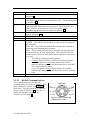
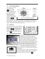
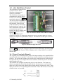
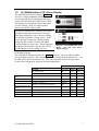
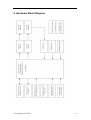
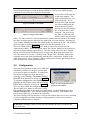
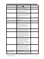
GOLD CONTROLLER
USER MANUAL
Revision:
Date:
3.3
February, 2003
© Tritium Pty Ltd 2003
Table of Contents
1.
Connection and Operation .....................................................................................1
1.1
Gold Power Controller...................................................................................2
1.1.1
High Power ............................................................................................2
1.1.1.1
Protection ...........................................................................................2
Controller Front Panel................................................................................2
1.1.2
1.1.2.1
1.2
RS-485 Communications ...................................................................3
(III.) 3-Phase Motor .......................................................................................4
1.2.1
Inductors ................................................................................................4
1.3
(II.) Hall Effect Sensors .................................................................................4
1.4
(IV.) Gold Driver Control ..............................................................................5
1.4.1
Screw Terminals (Signals).....................................................................5
1.4.2
(VI) Encoder Board................................................................................6
1.5
(V.) Multifunction LCD Driver Display.......................................................7
2.
Hardware Block Diagram ......................................................................................8
3.
Software .................................................................................................................9
4.
5.
6.
3.1
Programming the Controller ..........................................................................9
3.2
Programming the Driver Controls .................................................................9
Operation Procedures.............................................................................................9
4.1
Connection and Testing .................................................................................9
4.2
PhasorSense .................................................................................................10
Motor Controller Interface Program ....................................................................11
5.1
System Control.............................................................................................11
5.2
Configuration ...............................................................................................12
5.3
Parameter Values .........................................................................................16
Controller Communications Protocol ..................................................................18
© Tritium Pty Ltd 2003
1. Connection and Operation
A Tritium motor controller system is comprised of a number of components. The
description given in this section is for a typical arrangement of the motor drive system
and associated peripherals. Graphics shown are meant as an aid for system assembly
and are only representative of components that could possibly be used.
I.
Gold Power Controller
II. Hall Effect Sensors
III. 3-Phase Motor
IV. Gold Driver Controls
V. Gold Driver Display
VI. Digital Encoder
Figure 1. A typical arrangement for a motor controller system
© Tritium Pty Ltd 2003
1
1.1
Gold Power Controller
The Gold Power Controller is the hub of the drive system and the interface between
the driver and the motor. It has five high power connection points and a number of
low power digital and analog I/O ports that are accessed through various connector
sockets.
1.1.1 High Power
Two of the high power connection points, marked with +/- labels are for the voltage
bus. The controller and all peripheral products are powered from this power source,
unless otherwise stated. Breaking this power supply will disable all driving
capabilities of the controller. Residual charge in components will operate the
controller for a very brief time, after which the controller will become inert, disabling
any functionality of the electronics.
WARNING: The main supply to the controller should never be turned off whilst the
controller is still under load ie driving the motor.
The remaining 3 high power connection terminals (labelled A, B & C in Figure 1) are
the three phase connections from the motor.
Note: Cable lugs should be firmly attached by nuts in the screw terminals. Users
should avoid excessive tightening of these terminals as they can cause physical
stresses on internal circuitry that can lead to a reduced product life. All cables and
connectors should be rated appropriately and are chosen at the discretion of the user.
1.1.1.1
Protection
Tritium recommends that users should always fuse the connection between the high
power source and the motor controller. The fuse should be placed inline and be
preferably a DC fuse of the fast-blow variety. Doing so will minimise damage to the
controller caused by an external high power fault.
1.1.2 Controller Front Panel
Figure 2. The front panel of the motor controller
© Tritium Pty Ltd 2003
2
Label
Motor
Controls
Program / Run
Current
A
B
Status
Reset
1.1.2.1
Function
The connection socket for the motor signal cable described in
Section 0.
The connection socket for the RS-485 communications. This cable
can come from the Driver Control Board or a PC. Further details are
in Section 1.4.
This is a two position switch used when reprogramming the
controller DSP. During normal operation, it should be set to the
‘Run’ position. It should only be set to ‘Program’ when
programming the controller as outlined in Section 3.
This is the 4-way connection socket for the hard-current hall effect
sensors (Section 1.3).
General Pushbutton A
General Pushbutton B
The three status LEDs indicate the following:
GREEN – This will be on when there is power to the electronics in
the controller.
YELLOW – This LED will flash on and off when the controller is
receiving valid communications packets.
RED – This is a fault indicator and if activated, the controller will
not respond to any driving input signals. The controller will only
resume normal operation if the Reset button is pressed or the power
is cycled.
The LED is off during normal operation.
Constant flashing indicates a hard current limit shutdown
A repeated pattern of two flashes followed by a pause
indicates that the controller has shut down due to a bad hall
effect signal from the motor
A repeated pattern of three flashes followed by a pause
indicates the controller has shut down due to an overvoltage
error.
Pressing this button resets the software in the controller.
RS-485 Communications
The connector pinout for the RS-485
communications are shown in Figure 3. This
plug is labelled ‘Controls’ on the controller
front panel. This plug connects to either the
Driver Controls (Section 1.4) or to a PC to
enable configuration changes to the
controller (see Section 5).
Figure 3. Pinout of the RS-485
communications socket.
© Tritium Pty Ltd 2003
3
1.2
(III.) 3-Phase Motor
Apart from the three high
power connections
mentioned in Section
1.1.1, there are four
additional signals between
the motor and controller three hall effects and a
temperature sensor.
These signals interface
with the controller using
the plug and configuration
Figure 4. Motor signal plug pin diagram
shown in Figure 4.
The mandatory pins to be
connected are the +15V, GND and Hall signals. These provide power to the hall
effects inside the motor and the outputs are sent via the Hall lines. The MotorTemp
pins are optional, as they are intended to be used with a 10kΩ thermistor with a
negative temperature coefficient, inside the motor.
1.2.1 Inductors
Depending on the type of motor being driven,
phase inductors may be required. If this is
the case then they are to be arranged as
shown in Figure 5. Each phase lead will be
connected to an inductor before the lead
passes through a hall effect sensor (see
Section 1.3) or onto the power controller.
1.3
(II.) Hall Effect Sensors
Figure 5. Motor wiring arrangement
with inductors.
The Gold Power Controller uses a dual system
for regulating current flowing through the
controller to either the motor or power source.
The first system controls the current in response
to driver requests and adheres to set parameters.
This is performed by the onboard hardware.
The second system is a failsafe that protects the
controller by shutting down the hardware in the
event of an exceptional current surge outside of
the set limits. This ‘hard current’ system
Figure 6. Blue lines indicate direction of
requires that two high current hall effect sensors
phase leads through sensor windows.
each be placed around a phase lead from the
controller to the motor. It does not matter which phase
Front View
leads are used (A, B or C) or what orientation the sensors
+15V
-15V
are arranged in.
A
B
The hall effect sensors are connected to the controller by
Figure 7. Pinout for
means of 4-way micro-fit cables. They are daisy chained,
the Hall Effect socket.
in any order, and then connected to the socket on the
controller front panel shown in Section 1.1.2.
© Tritium Pty Ltd 2003
4
1.4
(IV.) Gold Driver Control
The Gold Driver Control acts as
a junction box for driver
interfaces, telemetry and
controller commands.
The Gold Power Controller (I.)
communicates with the Driver
Control via a custom RS-485
serial cable, shown in Figure 9.
The driver control sends the
requested driving conditions to
the controller, which in turn
sends all telemetry information
back to the driver controls. For
more information regarding the
communications protocol
between the driver controls and
the motor controller refer to
Figure 8. Connector functions of the Gold Driver Display
Section 6.
The standard DB-9 serial
connector is an RS-232 output port designed to convey telemetry data to a wireless
modem or computer for performance analysis. The baud rate for this port is fixed at
115200bps.
Figure 9. RS-485 Cable plugs and socket.
There is also a 6-way locking connector that goes to the Digital Encoder (refer to
Section 1.4.2) and two IDC output ports that send selected telemetry data to the Gold
Driver Displays (V.). Up to six Driver Displays can be ‘daisy chained’ on each IDC
ribbon cable.
1.4.1 Screw Terminals (Signals)
The 16 green screw terminals require some of the input switches to be attached before
operation of the motor controller. All of these switches should be normally-open two
position. The current and voltage levels used by the control board are small and will
not supersede the power ratings of the chosen switches and do not pose an electrical
shock hazard to the user.
The terminals are arranged in connection pairs for each function. The inputs are
adjacent to each other and will be labelled with the function name on one terminal
input and ‘GND’ on the other. Both of these inputs must be connected to work. Each
input pair also has a corresponding LED on the PCB. This LED will turn on when the
switch is in the ‘on’ position.
© Tritium Pty Ltd 2003
5
The following labelled connections must/should be connected before operation:
Label
Enable
Required
Mandatory
Function
Spare
Mandatory
Fwd/Rev
Switch
LH & RH
Brake
Strongly
Advised
Brakes
Kill Switch
Description
When the kill switch is in the off
position, all motor driving functions are
disabled regardless of user inputs.
When the kill switch is on, then normal
operation is resumed.
The direction switch indicates the
direction (forward or reverse) in which
to drive the motor.
Many applications using the Gold
Controller will use a dual braking
system for the motor – regenerative
braking and mechanical braking. A
switch that becomes closed when the
mechanical braking is used should be
connected to either (or both if there is
more than one mechanical system) of
these inputs. It will ‘zero’ the controls
and place the motor controller into
neutral. This prevents the controller
from driving the motor against the
braking system.
1.4.2 (VI) Encoder Board
The digital encoder used to drive the controller is a combined rotary encoder and
pushbutton. It is connected to the Gold Driver Control via a 6-way locking connector
cable.
To accelerate in the direction selected by the ‘Direction’ switch, described in Section
1.4.1, the encoder is turned in the clockwise direction. This increases the encoder
value. To reduce the acceleration at any time, the encoder can be turned in the
anticlockwise direction. Pressing down on the encoder shaft will push the button,
which zeroes the encoder and hence the throttle value.
Once the encoder value has reached zero, by either turning the encoder anticlockwise
or pressing the pushbutton, continuing to turn the encoder anticlockwise will activate
the regenerative braking system. Similarly to acceleration, turning the encoder
anticlockwise from zero will indicate the level of braking desired. The encoder value
will be negative during regenerative braking. Turning the encoder clockwise will
then reduce (become more positive) the level of braking until the encoder value
reaches zero. Again, pressing on the pushbutton will reset the controls to zero and
braking will cease.
There is also a red LED on the encoder PCB. The intensity of this LED increases as
the magnitude of the encoder value increases.
© Tritium Pty Ltd 2003
6
1.5
(V.) Multifunction LCD Driver Display
The Multifunction Driver Display (Figure 10,
top) uses a single pushbutton, labelled ‘Select’,
to cycle through four predetermined telemetry
values delivered from the Gold Driver Control.
The displays are 8-segment numeric and show
up to four digits. They are connected and
powered by an IDC ribbon cable.
The motor controller uses PWM control when
driving forward and current control in regen.
This control behaviour can be observed using
the Throttle and Motor Current values. If the
user is driving forward, the Throttle display
changes as the encoder is turned and Motor
Current displays a fixed value. When changing
into Regen, the Throttle value becomes fixed
and the Motor Current reading will vary.
Figure 10. The Multifunction LCD
Display (top) and LED Status
Display (bottom).
LED Status Display
The LED Driver Display is shown in Figure 10 (bottom). The two indicator lights
(left and right) are green. The remaining LEDs – Forward, Neutral and Reverse – can
be either red or green when turned on. The following table shows how these three
LEDs will be arranged for different driving arrangements.
LEDs
Direction Switch is Off
(FWD)
Situation
Forward
Neutral
Reverse
Kill Switch is Off
LH or RH Brake Switch is On (braking)
Off
RED
RED
GREEN
Off
RED
Throttle = zero (controller in neutral)
Throttle > 0 (driving)
Throttle < 0 (regenerative braking)
GREEN
GREEN
Off
GREEN
Off
Off
Off
Off
RED
Throttle = zero (controller in neutral)
Throttle > 0 (driving)
Throttle < 0 (regenerative braking)
Off
Off
RED
GREEN
Off
Off
GREEN
GREEN
Off
Direction Switch is On
(REV)
© Tritium Pty Ltd 2003
7
2. Hardware Block Diagram
© Tritium Pty Ltd 2003
8
3. Software
3.1
Programming the Controller
The controller uses a Texas Instruments TMSLF2407 DSP running at 40MHz.
I. Connect the RS-485 cable from the controller to a serial port on a PC – you
will require an RS-232 to RS-485 adapter board (Tritium can supply these if
required).
II. Set the Program/Run switch to the ‘Program’ position.
III. Reset the controller.
IV. Download the compiled software using relevant tools. Confirm that
programming was successful.
V. Return the Program/Run switch to the ‘Run’ position.
VI. Reset the controller.
3.2
Programming the Driver Controls
The Driver Controls are operated by a Texas Instruments MSP430 controller.
I. Connect a parallel port programmer (Tritium can supply these if required) to
the PC.
II. Using an 8-way IDC cable connect the programmer to the 8-pin IDC header
on the Driver Controls.
III. Reset the Driver Control board by cycling the power.
IV. Download the compiled software using relevant tools. Confirm that
programming was successful.
V. Disconnect the IDC connector from the board.
VI. Reset the Driver Control by cycling the power.
4. Operation Procedures
4.1
Connection and Testing
It is important to verify that the required components of the drive system are all
functioning correctly before operating outside of controlled conditions. Our
recommended testing procedure is as follows:
1. Connect the Gold Power Controller, Driver Controls, encoder board and
Driver Display as outlined in Section 1.
2. Connect the power source to the controller and turn on the system. You
should verify that all products have turned on and that the displays appear to be
showing the correct values.
3. Turn off the power and connect the motor.
4. Turn on the power and again verify that all units are powered and the displays
are operating correctly. Configure the motor using PhasorSense as outlined in
Section 4.2.
5. Using the digital encoder, carefully increase the power to the motor until it is
spinning at a reasonable speed (approx. 100rpm). Operate the motor for a brief
period, verifying that the driver displays are operating correctly. It will be
© Tritium Pty Ltd 2003
9
immediately obvious if there is a connection problem with the motor. Turn the
digital encoder back to a zeroed position and allow the motor to coast to a halt.
6. Repeat this test for the motor in reverse.
7. Again, test the motor and peripherals in both directions, but this time use the
regenerative braking to halt the motor.
8. Once these systems are operating correctly, connect any further peripherals
desired and test them.
9. Test the motor driving and regenerative braking for higher speeds and powers.
4.2
PhasorSense
The PhasorSense feature of the Gold Power
Controller is custom software that will detect the
phase/hall effect configuration of the motor.
After a motor has been connected to the
controller, the PhasorSense routine needs to be
run only once. The detected configuration is
recorded by the motor controller. Turning the
power off and on will not erase the
configuration.
Figure 11. Hall effect output and
The PhasorSense routine must be operated each
phase back EMF relationship.
time a new motor is connected or the existing
motor is reconnected.
1. Hold down the ‘B’ button shown in Figure 2.
2. While still pressing the ‘B’ button, press and release the ‘Reset’ button. Release
the ‘B’ button.
3. Make note of the configuration of the LEDs on the controller.
4. Manually spin the motor to a reasonable speed and wait for the LED pattern to
change.
5. Your phase configuration has now been recorded – you may operate the controller
as normal.
© Tritium Pty Ltd 2003
10
5. Motor Controller Interface Program
The Motor Controller Interface (MCI) program is a Windows™ based
program intended for bench testing the drive system and for changing
parameter settings of the controller.
To begin the program run the MCIprog.exe file. A window will
appear asking you which comm port the computer is connected to the motor controller
with. Select the appropriate port and then click OK. The program will only begin if
the Gold Power Controller is turned on and the communications are operating
correctly.
WARNING: It is recommended that you close all other Windows™ programs before
running the interface program. Failure to do so can cause communications errors.
5.1
System Control
Figure 12. MCI Prog Main Window
The program window in Figure 12 can be used to control the motor and to view all
available data. Each parameter value is displayed down the right hand side of the
window and is updated automatically. Further explanations of these parameters are
given in Section 5.3. There is a large button labelled ‘DISABLE CONTROLS’ that
turns the on-screen controls on and off to prevent accidental driving of the motor.
There are three control sliders that can be used to set the PWM, current or velocity to
drive the motor at. One of these sliders is shown in Figure 14. The program uses
either a PWM control method or a velocity control method, which is selected by
checking the box above the appropriate slider. When in either of these modes, the
© Tritium Pty Ltd 2003
11
controller will attempt to reach the desired PWM or velocity level whilst keeping
within the limits set by the Current Set Point slider.
Each control slider operates
in the same manner. The
slider is initially at the zero
point on the bar. If it is
moved to the right, then the
Figure 14. PWM Control Slider
set point is changed in the
forward direction, whilst
moving it to the left changes
the set point in the reverse
direction. The level set by
Figure 13. Regen control slider
the slider is reflected in the
window on the top left of the
slider. For finer control over the set point value, buttons that increment or decrement
the value in single steps are placed to the right of the set point window. Pressing the
‘Zero’ button instantly resets the slider back to the zero point on the bar. The window
to the top right of the bar shows the actual level that the controller is at.
There is a fourth slider (Figure 13) that is used to control the current level for
regenerative braking. When driving the motor, the ‘Regen’ button can be pressed at
any time to begin braking regeneratively. This also zeroes any of the drive signals.
Regen will only operate whilst the button is depressed. Releasing the button will
leave the motor free to coast. Clicking on the ‘Regen Lock’ checkbox will put the
controller into regen mode permanently until the box is unchecked. Similar to the
other sliders, there is also a display window with up/down buttons that change the set
point in single step increments/decrements.
5.2
Configuration
There are many parameters that can be modified
within the controller to configure its operation
for a specific motor or situation. To download
the current configuration from the motor
controller, select Config – Download Config
from MC from the menu as shown in Figure 15.
To edit this configuration select Config – Edit
Config from the window menu and the Config
Figure 15. The Config menu in the
Edit window will open as shown in Figure 16.
program main window.
Once you have edited the configuration, hit the
‘Record and Close’ button to close the Config
Edit window and return to the main program window. In the Config menu select
Upload Config to MC. Once this has completed successfully, your changes will
have been permanently recorded in the controller.
The Open Config from file and Save Config to file options allow you to save and load
custom configurations without having to retype parameter values every time the
controller configuration is changed.
WARNING Changing settings incorrectly may damage the power controller and
associated parts.
© Tritium Pty Ltd 2003
12
Figure 16. The Config Edit window allows users to modify parameters within the controller
Table 1. Parameters of the Config Edit window
Config Edit Parameters
Parameter
Last Programmed
MC Serial Number
Code Build
MC CAN Address
Over Voltage Cutout
Under Voltage Cutout
© Tritium Pty Ltd 2003
Description
Date and time stamp of the last time
the controller was programmed.
Unique serial number identifying the
motor controller.
Version and Revision of the software
program.
Can be set to the desired CAN
address to identify the controller on a
CAN Bus network.
When the input voltage is at this
value or higher, all controller
functions will be disabled and a
system reset is required to continue
operation. This SHOULD NOT be
set above the maximum bus voltage
stated in Section 1.
When the input voltage is at this
value or lower, all controller
functions will be disabled and a
system reset is required to continue
operation. This SHOULD NOT be
Dependent
Values
13
Motor Speed Const (k)
Motor Inductance
Current Limit
FET Current Scale
Factor
Nr of Poles in motor
Wheel Diameter
PWM Frequency
Motor Over Temp
Heatsink Over Temp
Controller Over Temp
SMPS Over Temp
© Tritium Pty Ltd 2003
set below the minimum bus voltage
given in Section 1.
The speed constant of the motor
being driven by the controller.
The inductance of the motor as seen
by the controller. This value should
include any external inductors
connected to the motor.
The maximum current supplied by
the controller to the motor. (This is
not the same as the current supplied
to the controller by the power
source.)
NOT ADJUSTABLE
Constant set by MOSFET hardware
characteristics.
The number of magnetic poles in the
motor.
Effective diameter of the wheel,
including the tyre, for a wheel motor.
This value should be scaled
according to any gearing systems
used if the motor is not a wheel
motor.
NOT ADJUSTABLE
The frequency that the MOSFETs
are switched at in the controller..
When the motor temperature reaches
this value or higher, the controller
will no longer drive the motor.
Users should experience a gradual
performance drop as the temperature
approaches this value.
When the heatsink temperature
measured by the controller reaches
this value or higher, the controller
will no longer drive the motor.
Users should experience a gradual
performance drop as the temperature
approaches this value.
When the ambient temperature
within the controller casing reaches
this value or higher, the controller
will no longer drive the motor.
Users should experience a gradual
performance drop as the temperature
approaches this value.
When the temperature of the internal
switched-mode power supply reaches
this value or higher, the controller
14
Auxiliary Over Temp
will no longer drive the motor.
Users should experience a gradual
performance drop as the temperature
approaches this value.
When the temperature of an auxiliary
board within the controller reaches
this value or higher, the controller
will no longer drive the motor.
Users should experience a gradual
performance drop as the temperature
approaches this value.
Table 2. Parameters of the Speed Control Loop dialog
Speed Control Loop Constants
Parameter
P 1/
I 1/
D 1/
Description
The denominator of the proportional scaling term
used in the speed control loop of the controller.
The denominator of the integral scaling term used
in the speed control loop of the controller.
The denominator of the differential scaling term
used in the speed control loop of the controller.
Dependent
Values
Table 3. Description of motor hall effect parameters.
Phasor Config
Note: The table in this dialog consists of three rows of data. The top row is for the case
that the EMF produced in phase path A-B is positive. The second row is for phase path
B-C and the bottom row is for phase path C-A.
Dependent
Parameter Description
Values
Hall numbers [0, 1, 2] correspond to Hall pins [1,
Hall Nr
2, 3] on the motor connection outlined in Section
0. Their row position in the table corresponds to
which of the hall effect lines from the motor is
active when phase A-B, B-C and C-A are active.
For example, if the number 2 was in the top row,
then Hall Effect 2 from the motor will be active
when the EMF of phase path A-B is positive.
The number of electrical degrees that a hall effect
Hall Lead
signal will lead (or lag if negative) the phase
voltages.
Hall Negate If a hall effect sensor is placed too far out of
alignment with a phase winding in the motor, then
the hall effect value may need to be negated to
obtain the best performance.
© Tritium Pty Ltd 2003
15
Table 4. Scaling parameters
Scaling Config
Dependent
Description
Values
The number that the corresponding parameter is
multiplied by when scaled.
The number that the corresponding parameter is
Divisor
divided by when scaled.
The number that is added after the parameter has
Offset
been scaled using the multiplier and divisor.
If checked, then the parameter value will be
Invert
inverted before it is scaled by the multiplier,
divisor or offset.
((((± [ parameter]) × [multiplier]) ÷ [divisor]) + [offset ])
Formula:
Bus Voltage The voltage at the input terminals to the controller.
MC Current The current supplied from the power source to the
controller (negative if in regen ie current flows
from the controller back into the power source).
The current that the controller is supplying to the
Motor
motor. This is negative if the motor is in regen.
Current
The temperature of the heatsink casing of the
Heatsink
controller.
Temp
The internal temperature of the motor.
Motor
Temp
15 Volt Rail The voltage level of the controller’s internal 15V
supply rail.
Parameter
Multiplier
5.3
Parameter Values
Parameter
Bad Packets
Bus Voltage
Controller
Current
Heatsink
Description
This is a red progress bar that will increase each time a
communications packet was not transmitted or received
correctly between the PC and the controller. It will decrease
with each correctly transmitted packet.
The voltage at the power input terminals to the controller.
The current supplied by the power source to the controller.
Formula
The temperature of the heatsink casing of the controller.
© Tritium Pty Ltd 2003
16
Temp
The internal temperature of the motor.
Motor
Temp
The internal ambient temperature of the controller case.
Controller
Temp
SMPS Temp The temperature if the internal switched mode power supply
of the controller.
The voltage level of the controller’s internal 15V supply rail.
+15V Rail
Voltage
Not Used
Adapter
Frequency
Not Used
Adapter
Channel 1
Not Used
Adapter
Channel 2
Not Used
Adapter
Channel 3
Not Used
Adapter
Channel 4
The general status bits from the communications packet,
General
displayed as a hexadecimal number. For descriptions of
Status
what each bit represents, refer to the communications
specification in Section 6.
© Tritium Pty Ltd 2003
17
6. Controller Communications Protocol
Comms specs for TRI07v4/TRI22v1/TRI23v1, as of 3/3/2003.
David Finn, James Kennedy.
All packets are to be sent most significant byte first (MSB
MSB first).
first
Operation mode
In operation mode there are 4 types of packets, they are as follows:
The driver controls are the master for the network. At a frequency of
between 4 and 10 Hz the driver controls must issue a driver controls info
packet. Faster then 10Hz can casue the controller to become over run and not
all the packets will be received, this does not worry the controller but
will become confusing to the driver controls, as it will not always get a
response to every packet it sends. Slower then 4Hz will casue the controller
to time out, when this happens the controller zeros the power to the motor
until it gets the next good packet.
Data
TRITIUM
Packet type
Data type
char[7]
char
Packet type -ve
Packet length
char
unsigned
short
unsigned
short
unsigned
short
long
long
16 bit check sum
16 bit XOR
Set Point PWM%
Set Point motor
current
Set Point
Velocity
Auxillary Command
Data
TRITIUM
Packet type
Packet type -ve
Packet length
16 bit check sum
16 bit XOR
Adj Set Point
PWM%
Adj Set Point
motor current
Adj Set Point
Velocity
Adj Auxillary
Command
Actual PWM%
Actual motor
current
Actual Velocity
Bus Voltage
Controller
current
Unit step
bytes
Comment
Start of packet header
1 = driver controls set
points
-1
Does not include the header
Does not include the header
Does not include the header
0.1%
mA
Send speed 0 if sending %
Always send current
long
mm/sec
Send 0% if sending speed
unsigned long
Code commands to do simple tasks.
0x00000001 = Horn
0x00000002 = Brake
0x00000004 = Right Indicator
0x00000008 = Left Indicator
0x00000010 = Stop Mode
Data type
Char[7]
char
char
unsigned
short
unsigned
short
unsigned
short
long
Unit step
long
mA
long
mm/sec
unsigned long
long
long
Code commands to do simple tasks.
0x00000001 = Horn
0x00000002 = Brake
0x00000004 = Right Indicator
0x00000008 = Left Indicator
0x00000010 = Stop Mode
0.1%
mA
long
long
long
mm/sec
mV
mA
© Tritium Pty Ltd 2003
bytes
Comment
Start of packet header
2 = motor controller info
-2
Does not include the header
Does not include the header
Does not include the header
0.1%
18
Heat Sink Temp
Motor Temp
Controller Temp
SMPS Temp
+15V
Adapter PCB Freq
Adapter PCB
Analog Channel 1
Adapter PCB
Analog Channel 2
Adapter PCB
Analog Channel 3
Adapter PCB
Analog Channel 4
General Status
long
long
long
long
long
long
long
m°C
m°C
m°C
m°C
mV
Hz
mV
long
mV
long
mV
long
mV
unsigned long
Coded reason
command.
0x00000001 =
0x00000002 =
0x00000004 =
0x00000008 =
0x00000010 =
0x00000020 =
0x00000040 =
for ignoring a driver control
Invalid Quadrant requested
Overvoltage
Heat Sink over temp
Motor over temp
+15V rail down
SMPS over temp
Controller over temp
Configuration Mode
In configuration mode there are two types of packets, there are as follows:
Data
TRITIUM
Packet type
Data type
char[7]
char
Packet type -ve
Packet length
char
unsigned
short
unsigned
short
unsigned
short
16 bit check sum
16 bit XOR
Data
TRITIUM
Packet type
Data type
char[7]
char
Packet type -ve
Packet length
char
unsigned
short
unsigned
short
unsigned
short
char[32]
16 bit check sum
16 bit XOR
Controller text
ID
Controller serial
number
code build number
major
minor
file programmed
Phasorsense
config
Vab Hall Nr
Vab Hall Negate
Vab Hall Lead
Phasorsense
config
Unit step
bytes
Comment
Start of packet header
5 = request current config
info
-5
Does not include the header
Does not include the header
Does not include the header
Unit step
bytes
Comment
Start of packet header
if sent from controller in
response to packet type 5 :
6 = current config info
if sent to controller :
7 = set config info to
-6 / -7
Does not include the header
Does not include the header
Does not include the header
Eg “GOLD CONTROLLER TRI07V4”
unsigned
long
000031
unsigned
char
unsigned
char
long
1
01
unsigned
char
unsigned
char
char
secs
1.01
secs since 1970 Jan 1
0 or 1
degrees
unsigned
© Tritium Pty Ltd 2003
19
Vbc Hall Nr
Vbc Hall Negate
Vbc Hall Lead
Phasorsense
config
Vca Hall Nr
Vca Hall Negate
Vca Hall Lead
Hall Fwd Seq
FET current
senseing scale
Current Loop
Proportional
constant
Current Loop
Intergral term,
minimum error
before change
Current Loop
Intergral term,
maximum didt I
term is allowed
to cause
Speed Loop P
Constant
Speed Loop I
Constant
Speed Loop D
over voltage
point
empty voltage
point
motor speed
constant (k)
motor & external
inductance
current limit
poles of the
motor
wheel diameter
PWM Freq
Motor overtemp
HeatSink overtemp
Controller
overtemp
SMPS overtemp
Auxiliary
overtemp
Bus Voltage
multiplier
Bus Voltage
divisor
Bus Voltage
offset
Bus Voltage
invert
Controller
current
multiplier
Controller
current divisor
Controller
current offset
Controller
current invert
char
unsigned
char
char
unsigned
char
unsigned
char
char
An array of
8 unsigned
shorts
unsigned
short
0 or 1
degrees
0 or 1
degrees
the hall
number
0x01, 0x03, 0x02, 0x06, 0x04,
0x05, 0x00, 0x00
((ADCdivVolt/(OpAmpGain*FETRe
s))/10) = 17
FETRes = 4mΩ
OpAmpGain = 2.13V/V
ADCdivVolt = 3223uV/adcdiv
0.025*65536 ~ 1638
P term is 0.025
unsigned
short
unsigned
short
1/100A
200
unsigned
short
1/100A
300
unsigned
short
unsigned
short
unsigned
short
long
40
mV
180000
long
mV
90000
long
uVs/rad
360000
long
uH
200
long
long
mA
5000
40
long
long
long
long
long
mm
Hz
m°C
m°C
m°C
500
20000
80
100
80
long
long
m°C
m°C
80
80
400
600
long
313500
long
1024
long
0
unsigned
char
long
0
long
1024
long
-101510
unsigned
char
0
© Tritium Pty Ltd 2003
200000
20
Motor current
multiplier
Motor current
divisor
Motor current
offset
Motor current
invert
Heat Sink Temp
multiplier
Heat Sink Temp
divisor
Heat Sink Temp
offset
Heat Sink Temp
invert
Motor Temp
multiplier
Motor Temp
divisor
Motor Temp offset
Motor Temp invert
+15
+15
+15
+15
multiplier
divisor
offset
invert
Can Address
Data
TRITIUM
Packet type
Packet type -ve
Packet length
16 bit check sum
16 bit XOR
long
10
long
1
long
0
unsigned
char
long
0
long
2048
long
0
unsigned
char
long
0
long
1
long
unsigned
char
long
long
long
unsigned
char
unsigned
long
165090
1
Data type
char[7]
char
char
unsigned
short
unsigned
short
unsigned
short
© Tritium Pty Ltd 2003
330000
-49029120
23100
1024
0
0
Unit step
bytes
Comment
Start of packet header
8 = set config info response
-8
Does not include the header
Does not include the header
Does not include the header
21
NOTICE
Tritium Pty Ltd (Tritium) reserves the right to make changes to their products or to
discontinue any product or service without notice. We would also advise customers
to ensure that all relevant information they obtain is current and complete. All
products are sold subject to the terms and conditions of sale supplied at the time of
order acknowledgement.
Tritium warrants performance of its products to the specifications given at the time of
sale, in accordance with the standard warranty. Products are tested to a suitable level
to support these specifications, although not all parameters will be tested for each
individual product.
Customers are expected to take necessary precautions to minimise operational hazards
involving the use of a Tritium product. Tritium accepts no responsibility for resulting
damage or loss to or by a product when operated outside the specified limits.
All intellectual property pertaining to products remains the sole property of Tritium.
Information published regarding third party products or services is not an indication
of Tritium’s endorsement or recommendation of these products in any way.
Copyright © 2002, Tritium Pty Ltd
© Tritium Pty Ltd 2003
22