1
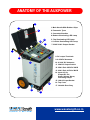
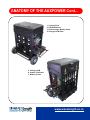
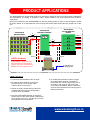
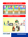
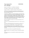
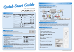
Take it Anywhere, Use it Everywhere!!
AUX POWER
USER’S MANUAL
INSTALLATION
MAINTENANCE
SERVICE
www.wavelength.co.in
SAFETY PRECAUTIONS / MAINTENANCE
Handling
!
SAFETY PRECAUTIONS
WARNING
In this manual, symbols are used to highlight warnings
and cautions for you to read so that accidents can be
prevented. The meanings of these symbols are as follows.
The unit shall be handled by
authorised persons having enough
knowledge of DC circuits.
Before connecting the AUXPOWER to
any other DC circuits extreme care to be
taken about the output voltage and the
polarity of both the systems.
This symbol indicates explanations about extremely
dangerous matters. If users ignore this symbol and
handle the device the wrong way, serious injury
WARNING could result.
Never attempt to parallel two
AUXPOWER of different output voltages
or more then five units at a time. Always
be sure about the polarity of the units at
both the ends.
This symbol indicates explanations about
dangerous matters. If users ignore this symbol and
handle the device the wrong way, bodily injury and
CAUTION damage to the equipment could result.
Never attempt to charge bulk battery
systems of the sub stations or any other
external batteries with the AUXPOWER
which will cause permanent damage to
the internal batteries of the unit.
!
!
Please observe the following safety tips
and precautions to ensure hazard-free use of
AUX-POWER.
!
CAUTION
Do not by pass the fuses and any
protection system of the equipment like
MCB, switch etc. of the unit, since this
can cause severe damage to the user
and the unit.
Power requirements
Since the power consumption of this unit is
fairly high when maximum output current is
drawn, we recommend to use the proper
1Ph.AC source with enough power as
indicated in the rating plate of the unit.
Always wear safety goggles, gloves,
and use proper tools while handling the
equipment.
MAINTENANCE
Always use the standard sockets, lugs,
clips, input and output cables supplied with
t h e u n i t . Av o i d j o i n t s a s f a r a s
possible.
!
!
WARNING
Environment
To prevent the risk of fire electric shock
or malfunctioning, avoid using
AUXPOWER in environments where it
will exposed to.
Extreme temperatures
Heat sources such as radiators or stoves
Very high humidity or high moisture
Excessive dust or sand
Excessive vibration or shock
CAUTION
AUXPOWER is built with the set of VRLA
batteries and they does not need regular
maintenance. As the expected life of the
VRLA batteries is about 4 to 5 years.
Regularly charge the system once in a
day or two for 2 to 3 hours even when not
in use. Never forget to charge the system
for 10 to 12 hours after every use.
Periodically check the air pressure of both
pneumatic tires and maintain the pressure
of 30 PSI for the best performance.
Clean the system with the dry soft cloth
daily. Do not use abrasive cleaner, wax or
solvents (such as paint thinner, or
cleaning alcohol) since, they may dull the
finish or damage the surface.
www.wavelength.co.in
Page-1
ANATOMY OF THE AUXPOWER
16
1. Main Handle With Rubber Grips
5
6
2. Pneumatic Tyres
3. Concealed Handles
4. Bottom Illuminating LED Lamp
5. Top Illuminating LED Lamp
13
12
6. Cubicle Illuminating LED Lamp
14
7. 230V 5A AC Output Socket
9
10
1
11
8
17
8. DC output Terminals
9. 0-25A DC Ammeter
10. 0-300V DC Voltmeter
7
11. 32A DC Output Switch
12. 25A 2 Pole 250V DC MCB
13. 63A 2 Pole 415V AC MCB
14. Input AC On,
Output DC On,
Under Voltage Alarm,
Indicating Lamps
15. 16A AC Input Socket
4
16. Top Cover
17. Variable Door Stay
2
15
3
www.wavelength.co.in
Page-2
ANATOMY OF THE AUXPOWER Cont...
1. Cooling Fans
2. VRLA Batteries
3. Draw out type Battery Rack
4. Charger PCB Rack
1
1
4
1
1
1
1
2
2
3
5. Charger PCB
6. Output Terminals
7. Battery Fuses
5
6
5
5
7
www.wavelength.co.in
Page-3
PRODUCT OVERVIEW
AUX POWER Provides safe DC power in the
yard or remote location during an emergency,
testing and maintenance of power and
protection equipments of the sub stations.
They are portable, quite, safe and re-chargeble
DC sources of power available in any standard
voltages.
SALIENT FEATURES
Long shelf life.
Maintenance free.
Easy to operate.
Tough and compact.
Fast recharge.
Totally weather protected.
Lightweight and portable.
Leak proof.
INTERNAL PROTECTION SYSTEMS
Active
Protection
Current Limiter & Inrush
Limiter on all Charger
Modules.
Passive
Protection
63A Input AC MCB.
25A Output DC MCB.
Thermal Overload,
Short Circuit Protection
for Charger Modules.
32A DC Fuses for all
Battery Banks.
Overcharge Protection
& Battery Low Voltage
Detector.
600V, 40A Reverse
Polarity Protection Diode.
www.wavelength.co.in
Page-4
PRODUCT APPLICATIONS
The AUXPOWER can be generally used as an emergency stored DC source at power plants, substations
and laboratories for testing of protective relays, circuit breakers and other electrical and electronic
equipments.
Apart from the above use, AUXPOWER can also be used typically in some of the emergency cases
as shown below. It is requested the user to study the below cases and make the proper use of the
unit.
SUB STATION
BATTERY BANK
SUB STATION
DC DISTRIBUTION
BOARD
SUB STATION
BATTERY CHARGER
1 A 2
F
3
4
V
LOAD 1
A
F
B
LOAD 2
1 C 2
F
3
LOAD3
4
F
LOAD 4
D
Circuit-1
AUXPOWER
Circuit-2
CASE-1 (Problem)
System battery charger has to be
disconnected for the maintenance
purpose, and some of the defective
batteries are to be replaced on line.
230V 1O 16A AC
Supply (+ 20%)
CASE-1 (Solution)
1. Connect the AUXPOWER to the AC Input.
2. DC Output cables shall be connected to
the terminal 2 & 4 of the output fuses
A &B as shown in the circuit 1.
3. Switch on the DC Output switch of the AUX
POWER and disconnect the faulty battery
circuit as soon as possible.
5. To isolate both the battery and the charger,
DC Output cables shall be connected to
the terminal 2 & 4 of the output fuses C & D
as shown in the circuit 2. and remove the
C & D fuses immediately. Now the whole DC
circuit is disconnected from the faulty system
without interruption.
4. Now the AUXPOWER will keep on supplying
the DC power to the whole system continuously
(if the system current is < 10A DC) till you finish
the replacement of the batteries.
www.wavelength.co.in
Page-5
PRODUCT APPLICATIONS Contd..
AUXPOWER
SUB STATION
DC DISTRIBUTION
BOARD
AUXPOWER
LOAD 1
1 C
2
3
4
F
1
2
LOAD 2
LOAD3
F
D
LOAD 4
230V 1O 16A AC
Supply (+ 20%)
CASE-2 (Problem)
System battery charger is burnt out
and the battery bank is about to empty.
The system DC load is about 18 Amps,
(1.8 times > AUXPOWER capacity)
and system has to be powered for at
least 7 to 8 days till the charger is
replaced.
SUB STATION
BATTERY BANK
V
A
SUB STATION
BATTERY
CHARGER
CASE-2 (Solution)
1. Connect 2 or 3 AUXPOWER to get the output
of 18 Amps or more.
(With the unique current share design of the
system, 2 to 3 AUXPOWER units can be
paralleled to get more output.)
2. DC Output cables shall be connected to
the terminal 1 & 3 of the output fuses C & D
as shown in the circuit.
5. The AUXPOWER can be used as a
substitute to the substation battery bank
and the charger for any number of days
if the AC input is made available
continuously to the unit.
If AC is not available, a fully charged unit
can supply 10 Amps current for maximum
of 45 minutes to 1Hour.
3. Switch on the DC Output switches of both the
AUXPOWER and disconnect the faulty battery
and the battery charger as soon as possible.
6. Even though the AUXPOWER is designed
for continuous10A DC output rating, it can
withstand the surge currents up to 30 to 40
Amps for more than 30 seconds.
4. Now both the AUXPOWER will keep on supplying
the DC power to the whole system continuously
even if the system load current is 18A DC.
7. The system is equipped with low battery
indicating alarm at 85% of the rated voltage
during the operation on battery.
www.wavelength.co.in
Page-6
REPLACEMENT OF BATTERIES & TYRES
Draw out design of the system allows the user to replace the batteries
in 7 easy steps
2
1
Open both the side covers
by removing the screws
Un-screw the screws of the battery
racks
Open the fuses of the battery &
disconnect wires from the terminal
5
4
Pullout the wiring of the battery
Draw out the battery rack
3
6
Remove the screws of the battery
holder
7
Replacing of pneumatic wheels
Replace the battery
Remove the bolt
Pullout the wheel from the shaft
www.wavelength.co.in
Page-7
SMF BATTERY CHARACTERISTICS
Discharging Current & Discharge Duration Time
Dimensions (mm)
10
98 1
151 1
9
8
3
2
60
50
40
(min)
1
-
6
5
4
Discharge time
1
95
101
(h)
7
+
30
20
10
40
C(104
8
25
C( 77
)F
6
0
C( 32
)F
)F
4
0
0.41
1.24 1.441.73 2.5 4.5 7.412.424.9 40 58
0.85
Discharge Current (A)
Standard Terminal
(mm)
Standard
Terminal
(mm)
Discharge Characteristics (25ºC ,77ºC)
F1/F2
4.75
13
12
Loading Voltage(V)
3.2
6.35
0.8
11
10.5
9.6
12A
36A
5 hour rate (2.1A)
10.5AH
1 hour rate (7.07A)
7.24AH
1.5
3
Initial Charging Current
10 hour rate (1.11A) 11.1AH
less
Cycle
Constant-
0.60A
9
0
Rated
Capacity
1.1A
7.24A
8
7.8
Electrical Specification
20 hour rate (0.60A) 12.0AH
3.1A 2.1A
10
5
12
24A
20
30
60 2
3
5
10
20
h
min
Discharge Time
than 3.6A.Voltage
14.4V~ 15.0V at 25C
º
(77F)
º
Temp. Coefficient -30mV/C
º
Physical Specification 12V 12Ah. 20Hr Rating
Voltage
Capacity
affected by
Temperature
40C
º
(104F)
º
103%
25C
º
(77F)
º
100%
0C
º
( 32F)
º
86%
No limit on Initial Charg-
Charge
Standby
ing
Current
Voltage
Dimension
13.5V~13.8V at 25C(77F)
º
º
Temp. Coefficient - 20mV/C
º
Length X Width X Container Height
151 X 98 X 95
Total Height (with Terminal)
Weight
101
1mm
Approx 3.85kg
Standard Terminal
1mm
F1/F2
Constant Current Discharge Characteristics Unit: Amperes (25ºC, 77ºF)
F.V/Tim
5MIN
10MIN
15MIN
30MIN
1HR
2HR
3HR
4HR
5HR
8HR
10HR
20HR
1.60V
e
46.3
31.5
23.3
13.8
7.81
4.46
3.38
2.71
2.22
1.45
1.21
0.629
1.67V
39.9
28.1
21.1
12.8
7.44
4.27
3.22
2.58
2.11
1.43
1.18
0.623
1.70V
38.1
26.9
20.5
12.4
7.29
4.20
3.15
2.54
2.09
1.42
1.17
0.617
1.75V
34.6
24.6
19.2
11.9
7.07
4.04
3.06
2.48
2.06
1.40
1.16
0.606
1.80V
30.7
22.4
17.6
11.5
6.76
3.90
3.00
2.42
1.99
1.37
1.15
0.600
1.85V
22.9
17.5
14.5
9.72
6.03
3.57
2.79
2.27
1.85
1.30
1.08
0.594
Constant Power Discharge Characteristics Unit: Watts (25ºC, 77ºF)
F.V/Time
5MIN
10MIN
15MIN
30MIN
1HR
2HR
3HR
4HR
5HR
8HR
10HR
20HR
1.60V
460.7
320.9
244.5
150.9
88.1
50.8
38.7
31.3
25.7
17.04
14.22
7.43
1.67V
409.6
294.6
226.5
141.6
84.7
48.9
37.1
29.9
24.6
16.80
13.96
7.37
1.70V
393.3
282.9
220.3
137.6
83.3
48.3
36.4
29.5
24.4
16.69
13.83
7.31
1.75V
367.4
265.5
209.3
133.0
81.0
46.6
35.4
28.8
24.1
16.47
13.71
7.18
1.80V
332.9
245.6
194.0
129.1
77.8
45.1
34.9
28.3
23.3
16.23
13.59
7.12
70.1
41.6
32.6
26.6
21.8
15.35
12.85
7.06
www.wavelength.co.in
Page-8
INTERNAL WIRING DIAGRAM
BATTERY RACK 1
X1
1
2
3
4
5
6
X2
1
2
X6
X7
AC INPUT
H1
AC
Distribution
Board
E
H2
J1
1
J2
2
3
4
n
Battery Charging Modules
1
2
3
4
5
6
7
8
1
2
BATTERY RACK 2
L21
L22
1 2 3 4 5 6 7 8 9 10 11 12
DC OUTPUT
LED
Driver
L31
9
10
11
12
X3 1 2 3 4 5 6
DC
Distribution
Board
L11
L12
L32
UV
Circuit
L41
1 2 X5
BATTERY CHARGER
RACK
EXT LAMP
CONNECTOR
INTERNAL ILLUMINATING
LAMPS
440V
63A AC MCB
0- 300V DC
VOLTMETER
V
230V 1O 5A AC
SOCKET
7 1
4 5
0-20A DC
AMMETER
A
7 1 4
230V 1O 16A
AC INPUT
5
25A SHUNT
25A DC MCB
32/60A DC
ON/OFF SWITCH
BATTERY LOW
VOLTAGE INDICATOR
AC MAINS ON
INDICATOR
O/P DC ON
INDICATOR
600V 40/80A
DIODE
COMPONENT
PLATE
DC O/P
TERMINALS
DC O/P
TERMINALS
www.wavelength.co.in
Page-9
AUX POWER
110A
AUX POWER
48
AUX POWER
48A
220V DC
10A / 1Hour
110V DC
10A / 1Hour
110V DC
20A / 1Hour
48V DC
20A / 1Hour
48V DC
40A / 1Hour
TOTAL No. Of
BATTERIES
(12V, 10A X n)
MAXIMUM
OUTPUT
CURRENT
METERING
PROTECTION
V
A
3 Digit
(Digital)
3 Digit
(Digital)
18
0-300V
DC
0-20A
DC
9
0-300V
DC
0-20A
DC
18
0-300V
DC
0-40A
DC
8
0-150V
DC
0-40A
DC
16
0-150V
DC
0-80A
DC
UNIT WEIGHT
(Approximate)
INPUT
63A 415V AC MCB
AUX POWER
110
OUTPUT
VOLTAGE
(+/- 15 %)
VRLA
(Maintenance Free)
AUX POWER
220
1Ph. 230V 50Hz (+/- 5Hz)
AC SUPPLY
PRODUCT
INPUT
VOLTAGE
(+/- 15 %)
BATTERY
TYPE
TECHNICAL SPECIFICATIONS
OUTPUT
25A 250V DC MCB
32A DC FUSE
160Kg.
25A 250V DC MCB
32A DC FUSE
110Kg.
63A 250V DC MCB
64A DC FUSE
160Kg.
63A 100V DC MCB
64A DC FUSE
110Kg.
63A 100V DC MCB
64A DC FUSE
160Kg.
GENERAL SCHEMATIC
BATTERY LOW
VOLTAGE INDICATOR
+
230V 1O 5A AC
Socket
230V 1O 16A AC
Supply (+ 20%)
P
E
_
BATTERY LOW
VOLTAGE DETECTOR
CIRCUIT
N
POWER SUPPLY UNITS
63A AC MCB
0-20A DC
AMMETER
25A DC MCB
600V 40/80A
DIODE
A
V
O/P DC ON
INDICATOR
0- 300V DC
VOLTMETER
AC MAINS ON
INDICATOR
32/60A DC
ON/OFF SWITCH
+
_
DC O/P
TERMINALS
LED DRIVING
CIRCUIT
32A X 2 FUSE
CUBICAL
ILLUMINATOR
LAMP 1
ON/OFF
EXTERNAL
LIGHT 1
LAMP 2
ON/OFF
EXTERNAL
LIGHT 2
LAMP 3
ON/OFF
FLOOD
LIGHT
(OPTIONAL)
LAMP 4
ON/OFF
12V X 10AH X (n) No.
VRLA BATTERY
PACK
www.wavelength.co.in
Page-10
DIMENSIONAL DETAILS
772
BOTTOM VIEW
560
665
FRONT VIEW
1000
450
SIDE VIEW
260
852
*All Dimensions are in mm
TOP VIEW
*Any design and the dimensions of the products are subject to change
without prior intimation.
www.wavelength.co.in
Page-11
Office:
# 21, “AM Elegance”, Basement Floor,
17th Cross, MRCR, Near Maruthi Mandir,
Vijaynagar, Bangalore - 560 040.
Ph. +91 80 23506771.
B-610, BSEL Tech Park,
Plot No-39/5 & 39/5A, Sector 10A,
Vashi, Navi Mumbai-400703
Ph. +91 22 66099096.
E-mail: [email protected]
www.wavelength.co.in
Wlt-Publ.-De-1112-V003
AUX POWER
Works:
Take it Anywhere, Use it Everywhere!!
CONTACT US :-