1
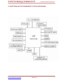
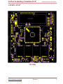
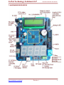
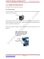
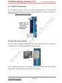
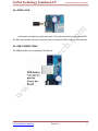
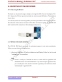
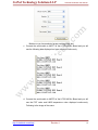
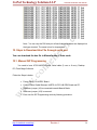
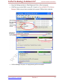
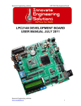
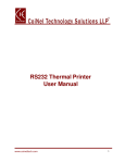
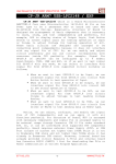
LPC2148 DEV BOARD User Manual www.coineltech.com www.coineltech.com CoiNel Technology Solutions LLP LPC2148 Dev Board User Manual Designed by CoiNel Technology Solutions LLP nd th th No-816, 2 Floor, 4 B Cross, 9 A Main, RPC Layout, Vijaynagar, Bangalore-560040 State: Karnataka Country: India www.coineltech.com For any questions or issues submit them to [email protected] Designations used by companies to distinguish their products are often claimed as trademarks. In all instances where CoiNel is aware of trademark claim, the product name appears in initial capital letters, in all capital or in accordance with the vendor’s capitalization preference. Users should contact appropriate companies for more complete information on trademark and trademark registrations. All trademarks and registered trademarks in this manual are the property of their respective holders. No part of this manual may be reproduced or distributed in any form or by any means, or stored in the database or retrieval system, without the prior written permission from CoiNel Technology Solutions LLP; with the exception that the listings may be entered, stored and executed in a computer system, but they may not be reproduced. The content in this manual are presented for instruction value. The details have been carefully tested, but are not guaranteed for any particular purpose. CoiNel Technology Solutions does not offer any warranties and does not guarantee the accuracy, adequacy, or completeness of any information herein and is not responsible for any errors or omissions. CoiNel Technology Solutions LLP assumes no liability for damages resulting from use of such information in this manual or for any infringement of intellectual property rights of third parties that would result from use of this information. This evaluation board/kit is intended for use for ENGINEERING DEVELOPMENT, DEMONSTRATION and EDUCATION OR EVALUATION PURPOSES ONLY and is not considered by CoiNel Technology Solutions LLP to be a finished end-product fit for general consumer use. Persons handling the product(s) must have electronics training and observe good engineering practice standards. As such, the goods being provided are not intended to be complete in terms of required design-, marketing-, and/or manufacturing related protective considerations, including product safety and environmental measures typically found in end products that incorporate such semiconductor components or circuit boards. The user assumes all responsibility and liability for proper and safe handling of the goods. Further, the user indemnifies CoiNel Technology Solutions LLP from all claims arising from the handling or use of the goods. Due to the open construction of the product, it is the user’s responsibility to take any and all appropriate precautions with regard to electrostatic discharge. EXCEPT TO THE EXTENT OF THE INDEMNITY SET FORTH ABOVE, NEITHER PARTY SHALL BE LIABLE TO THE OTHER FOR ANY INDIRECT, SPECIAL, INCIDENTAL, OR CONSEQUENTIAL DAMAGES. CoiNel Technology Solutions LLP assumes no liability for applications assistance, customer product design, software performance, or infringement of patents or services described herein. http://coineltech.com/shop/ Revision 1 1 CoiNel Technology Solutions LLP LPC2148 Dev Board User Manual Change Log The version of the development: Revision LPC2148DEVBRD1.1 Document Version: Manual_LPC12148DEVBRD1.1 http://coineltech.com/shop/ Revision 1 2 CoiNel Technology Solutions LLP LPC2148 Dev Board User Manual TABLE OF CONTENTS 1. INTRODUCTION 4 2. HANDLING WARNINGS 5 3. KIT DELIVARABLES 5 4. BOARD USE REQUIREMENTS 6 5. FUNCTIONAL BLOCK DIAGRAM 7 6. BOARD LAYOUT 8 7. HARDWARE RESOURCES 9 8. IO CONNECTOR DESCRIPTION 10 9. VALIDATING LPC2148 DEV BOARD 16 10. STEPS TO DOWNLOAD HEX FILE THROUGH SERIAL PORT 20 http://coineltech.com/shop/ Revision 1 3 CoiNel Technology Solutions LLP LPC2148 Dev Board User Manual 1. INTRODUCTION ARM7 LPC2148 is a 16/32 bit ARM7TDMI-S Core Microcontroller from Philips (NXP). LPC2148 includes built in peripherals such as USB, ADC, DAC, Timer/Counter, PWM, Capture, RTC, I2C, SPI, UART etc. LPC2148 Dev Board is optimized to save development time in typical embedded control applications. The Dev Board is an extension of a basic header board and has an important peripheral interface assembled for evaluation and testing. About 20 IO are connected via standard 2.54mm berg connectors (This can be used to connect graphical LCD, 4x4 Matrix Keyboard or other interface as required). The functional details of the board are as follows: 16/32 Bit ARM7TDMI-S MCU No.LPC2148 from Philips (NXP) Has RS232 Communication Circuit for 2 Channels (UART0 and UART1). Has micro SD card connectivity. USB device Option. Has EEPROM interface using I2C. Has PS2 keyboard interface. Has audio Interface. Analog input via AD0.1 I/O pin out for different interfaces. Onboard 16*2 LCD. Onboard 7 segment displays via I2C. On Board Graphical LCD Connectivity option. (Can also be used as GP IO) On Board 4x4 matrix keypad Connector. (Can also be used as general purpose IO) On Board Temperature Sensor connected to AD0.2. On Board Buzzer and Relay. Onboard Reset and ISP Switches. On Board Power Supply Circuit for +5V and +3.3V (USB or external power Source input options) On Board 12 MHz Oscillator. http://coineltech.com/shop/ Revision 1 4 CoiNel Technology Solutions LLP LPC2148 Dev Board User Manual 32.768 KHz Clock for RTC. Option for a CMOS Battery. Onboard 20 pin JTAG connector for debugging/programming applications. LED for Power Supply, USB and Test LED. Power Supply – DC input 7.5 - 9V/ 500mA - 1A. Board Dimensions 125 x 139 mm2. Material: FR4, Finish: ENIG. 2. HANDLING WARNINGS The Kit must not be subjected to high electrostatic potentials. General practice for working with static sensitive devices should be followed when working with the LPC2148 DEV Board. Board must always be handled at properly designated work areas. When not being worked on, the board must be enclosed in the box and stored safely. Avoid touching the circuits or components. Stacking of circuit boards and assemblies should be avoided to prevent physical damage. 3. KIT DELIVERABLES LPC2148 DEV Board. USB Cable. CD that contains, KEIL evaluation version installer, Flash Magic Installer, H JTAG installer schematics, user manual and related documents, hex files for various peripherals, Keil project and workspace for implementing peripherals and few example project codes. http://coineltech.com/shop/ Revision 1 5 CoiNel Technology Solutions LLP LPC2148 Dev Board User Manual 4. BOARD USE REQUIREMENTS To test and evaluate the board, we recommend the following configurations PC with 2.0 GHz or higher CPU, 512 MB or above RAM, USB Port, Serial Port. (Will need a Parallel Port if a Parallel JTAG is being used) Operating System (We recommend Windows XP, since most of our testing is done on same platform, although other OS can also be used) Integrated Development Environment (We recommend Keil 4. Other compatible IDE can be used). Debugging/Programming Tool (We recommend HJTAG if Parallel Port JTAG is used, CoiNel ARM USB JTAG has been checked on Rowley Crossworks). Known Issue: CoiNel ARM USB JTAG does not work for LPC2148 on Kiel UVision To test all the features of the board, you would also require a USB Cable (A to B), a Micro SD Card, Speakers or Headphones, PS2 Keyboard, Serial cable and DC power adapter (7.5V-9V/1Amp DC). The board can also be powered by USB and hence use of DC power adapter is not always required. 4x4 matrix keyboard and graphical LCD can also be tested. These boards are sold separately and can be purchased at www.coineltech.com/shop http://coineltech.com/shop/ Revision 1 6 CoiNel Technology Solutions LLP LPC2148 Dev Board User Manual 5. FUNCTIONAL BLOCK DIAGRAM OF LPC2148 DEV BOARD http://coineltech.com/shop/ Revision 1 7 CoiNel Technology Solutions LLP LPC2148 Dev Board User Manual 6. BOARD LAYOUT TOP VIEW http://coineltech.com/shop/ Revision 1 8 CoiNel Technology Solutions LLP LPC2148 Dev Board User Manual 7. HARDWARE RESOURCES http://coineltech.com/shop/ Revision 1 9 CoiNel Technology Solutions LLP LPC2148 Dev Board User Manual 8. IO CONNECTOR DESCRIPTION The details of the IO connections are as follows 8.1. DC Power Input The Power supply to be used has to be 7.5V to 9V DC, 1Amp. The DC jack connectivity details are shown in the figure. A slide switch is provided for power ON/OFF control. The slide switch is useful only when an external DC adapter is used. When USB is used to power the board, the switch condition will not have any effect on the power input. When using the adapter, sliding the switch towards the arrow shown in figure will turn the board ON. http://coineltech.com/shop/ Revision 1 10 CoiNel Technology Solutions LLP LPC2148 Dev Board User Manual 8.2. JTAG 20 Pin Box Header The box header will be used to connect the JTAG for Debug/Programming. A 20 Pin IO Cable can be connected here which connects from a Parallel/USB JTAG. You can buy the Parallel or USB JTAG at http://www.coineltech.com/shop 8.3. Micro SD Card Connector The correct way of inserting the SD card is given below. Pressing the card in the direction shown will lock the card. Make sure the card is properly inserted. Note: To remove the card, press the card gently in the same direction shown above and then letting it loose. The card will easily pop out and can be removed. http://coineltech.com/shop/ Revision 1 11 CoiNel Technology Solutions LLP LPC2148 Dev Board User Manual 8.4. AUDIO JACK Audio jack is provided for plug & play audio. The audio connectivity is via internal DAC. The DAC has a jumper (J9) just in case you want to connect the DAC output to other devices. 8.5. USB CONNECTIONS The USB provided can be used as an End Device. http://coineltech.com/shop/ Revision 1 12 CoiNel Technology Solutions LLP LPC2148 Dev Board User Manual 8.6. Analog Input The POT is connected to AD0.1 8.7. Reset and ISP Switch The reset switch can be used for resetting the CPU and ISP (In system programming) switch will be used during external interrupt/programming. The details of programming LPC2148 in ISP mode is given in detail in programming section. http://coineltech.com/shop/ Revision 1 13 CoiNel Technology Solutions LLP LPC2148 Dev Board User Manual 8.8. 4x4 Matrix Keypad connector bergs Note: Apart from connecting 4x4 matrix keypad, these bergs can also be used as IO pins for other applications. 8.9. Graphical LCD connector bergs http://coineltech.com/shop/ Revision 1 14 CoiNel Technology Solutions LLP LPC2148 Dev Board User Manual Note: Apart from connecting Graphical LCD, these bergs can also be used as IO pins for other applications. 8.10. Jumper connections for TEST LED, BUZZER and RELAY The test led, buzzer and relay are connected via port pin P0.10. http://coineltech.com/shop/ Revision 1 15 CoiNel Technology Solutions LLP LPC2148 Dev Board User Manual 9. VALIDATING LPC2148 DEV BOARD 9.1. Powering the Board The board can be powered using an adapter or through the USB. Connect the adapter (7.5V9V/ 1 Amp) to the DC Jack provided and slide the switch towards ON Position. The details are shown below. You can also power the board using USB by connecting the USB A to B Connector as shown. The other side of the cable is connected to PC. When the Power is applied, the POWER LED (D11 beside the DC Jack) will turn ON indicating board power up. 9.2. TESTING FOR BOARD WORKING The LPC2148 DEV Board comes with the preloaded program to test various peripherals. When you power the board for the first time, 1. After about 3 seconds. LCD will be initialized and will Display “CoiNel” on first line and ”coineltech.com” on second line. Note: There is a delay of 3 seconds as there is a code written for graphical LCD initialization before 16x2 LCD initialization. If you have brought a graphical LCD, you can shift pins of J2, reset the controller by pressing reset switch and check data displayed on graphical LCD. http://coineltech.com/shop/ Revision 1 16 CoiNel Technology Solutions LLP LPC2148 Dev Board User Manual In case you have checked for graphical LCD working, switch off the board, shift J2 back for 16 x 2 LCD and restart the board. This is done as other peripheral checking information is displayed only on 16 x 2 LCD. 2. EEPROM Data will be checked and the corresponding messages will be displayed on 16 x 2 LCD. Note : If the EEPROM read/write is correctly executed, the Test LED also turns ON provided J18 is connected to Test LED 3. 7 Segment Test message will be displayed. An up counter from 0 to 10 will be displayed on 7 segment displays. 4. SD Card Check Process will be displayed If the card is not inserted, a “card not detect” message will be displayed and the SD Card process is completed. If the card is inserted, “card detect” message will be displayed and sample text file will be written and read from the SD card. This would confirm the SD card initialization and communication. Note: You can use a card reader and see if a text file is created in the SD Card for confirmation. 5. “Press Any key” message will be displayed followed by which the TEST LED will blink for some time. Press key is for PS2 keyboard interface. 6. The TIME data is displayed continuously and will keep updating starting from 00:00:00. Make sure you have a CMOS Battery connected. http://coineltech.com/shop/ Revision 1 17 CoiNel Technology Solutions LLP LPC2148 Dev Board User Manual Note: 1. If you enter any data using PS2 Keyboard, the same will be displayed on LCD. 2. If you connect a speaker or a headphone to the audio jack, you will hear a repetitive beep sound. 3. Checking Serial Port a. Make sure your serial port of PC is working. If you are using 9 core cable, make sure J23 jumper on LPC2148 DEV Board is removed. Note: J23 is used during AUTO code download mode on UART0 and is used to make the microcontroller enter into programming mode. Having J23 connected and using UART0 can reset the board. The second option is to use a 3 core cable which uses TX, RX and GND and J23 jumper connectivity will not be a issue at all. b. Open Hyper terminal and have the following setting for COM Port http://coineltech.com/shop/ Revision 1 18 CoiNel Technology Solutions LLP LPC2148 Dev Board User Manual Make sure you have selected proper working COM port. c. Connect the serial cable to UART1 of the LPC2148 Dev Board and you will see the following data displayed on hyper terminal continuously d. Connect the serial cable to UART0 of the LPC2148 Dev Board and you will see the POT value and LM35 temperature value displayed continuously. Following is the image of the same. http://coineltech.com/shop/ Revision 1 19 CoiNel Technology Solutions LLP LPC2148 Dev Board User Manual Note: `You can vary the R24 and you will see that the variations are displayed on the hyper terminal. The same is true for temperature. 10. Steps to Download Hex File through serial port You can download the hex file in Manual mode or Auto mode 10.1. Manual ISP Programming You need to have LPC2148 DEV Board, Serial cable (3 core or 9 core), Desktop PC, Flash Magic Software. Follow the Steps is below: Power ON LPC2148 DEV Board. Connect Serial Cable Between UART0 of LPC2148 DEV Board and PC. Make sure jumper (J8) is connected towards Manual Mode. Make sure jumper (J23) is removed. Enter into the ISP Programming mode by following procedure. http://coineltech.com/shop/ Revision 1 20 CoiNel Technology Solutions LLP http://coineltech.com/shop/ Revision 1 LPC2148 Dev Board User Manual 21 CoiNel Technology Solutions LLP Open Flash Magic Software in PC. Click on Options and select Advance Options. LPC2148 Dev Board User Manual In Advance Options, make sure Use DTR and Assert DTR are unchecked. Click on OK after making changes if required. http://coineltech.com/shop/ Revision 1 22 CoiNel Technology Solutions LLP LPC2148 Dev Board User Manual Keep the Settings as below in Flash Magic and Click on Start to program. COM Port may not be COM1 in every PC, Check it in Ports (COM & LPT) in Device Manager. Make sure you have connected to the proper COM port that is selected. If All the Settings are proper, the programming will be successful. http://coineltech.com/shop/ Revision 1 23 CoiNel Technology Solutions LLP LPC2148 Dev Board User Manual 10.2. AUTO Programming You need to have LPC2148 DEV Board, Serial cable (9 core), Desktop PC, Flash Magic Software. Follow the Steps is below: Connect full Serial Cable (9 Core) Between UART0 of LPC2148 DEV Board and PC Serial Port. Make sure jumper (J8) is connected towards Auto Mode. Make sure jumper (J23) is connected. Power ON LPC2148 DEV Board. Open Flash Magic Software in PC. Click on Options and select Advance Options. In Advance Options Keep the Settings as shown below. Click ok to save settings and go back to Flash Magic main page option. http://coineltech.com/shop/ Revision 1 24 CoiNel Technology Solutions LLP LPC2148 Dev Board User Manual Keep the settings as below in Flash Magic. After browsing the appropriate file to be loaded, click start. If All the Settings are proper, the programming will be successful. Important Note: You need to remove jumper (J23) so that the code loaded starts executing. If required, you can also reset the board. http://coineltech.com/shop/ Revision 1 25 CoiNel Technology Solutions LLP LPC2148 Dev Board User Manual AFTER-SALE SERVICE CoiNel is at your service, and we have special Technical Support Engineers to provide support and consultation in forms of telephone and E-mail. TEL: +91-80-23154423 Technical Support E-mail: [email protected] For any questions or concerns submit them to [email protected] http://coineltech.com/shop/ Revision 1 26