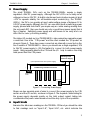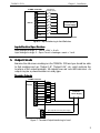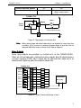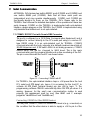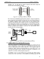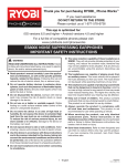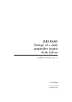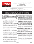
1
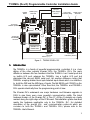
T100MX+ (Rev D) Programmable Controller Installation Guide
+
COMM3
RS485
COMM2 (DTE)
Male DB9
+24V DC
Power
Supply
for PLC
Output LED
Indicators (Red)
Digital Output
Terminals
Analog I/Os
Female DB15
connector
126mm (4.95”)
To Host PC
RS232C (COMM1)
T100MX+
Super PLC
Warning: Warranty Void
if this label is damaged
0V
62256LP-12
CMOS RAM
Digital Input
Terminals
183mm (7.2”)
Input LED
Indicators (Green)
Figure 1 - T100MX-3224R+ PLC
1. Introduction
The T100MX+ is a family of powerful programmable controllers. It is a close
sibling of the other popular M-series PLCs: the T100MD+ PLCs. The main
difference between the two families is that the T100MX+ has 3 serial ports but
no built-in LCD port, whereas the T100MD+ has a built-in LCD port but
eliminated the second RS232 serial port. Yet another difference being that
T100MX+ employs bi-directional opto-isolated input drivers which can interface
to both the PNP and the NPN type of inputs. The first RS232 port COMM1 on the
T100MX+ is also opto-isolated. Other than that, the T100MX+ and T100MD+
PLCs operate identically from the programming point of view.
The M-series PLCs underwent one major hardware and firmware upgrade in
1999 to give them even more powerful communication ability. The latest
hardware revision of the M-series PLC is “Rev D”. All Rev D designs are clearly
marked along the right edge of the PCB board. This installation guide describes
mainly the hardware applicable only to the T100MX+ PLC. For detailed
description of the special I/Os and communication protocols which are
common to both the T100MX+ and T100MD+ PLCs, please refer to the
T100MD+ User’s Manual.
1
T100MX+ PLCs
Chapter 1 : Installation
Members of the T100MX+ differ only in their digital ON/OFF I/O combination. We
will be introducing a few standard models from 32 to 128 I/Os. Special I/O
combinations can also be custom-made for OEM customers requiring more
than 300 PLCs per year. Models of T100MX+ PLC are defined as follows:
T 1 0 0 M X - 3
CPU Type
2
No. of Inputs
2
4
R
+
No. of Outputs With some
Relay Outputs
In the above example T100MX-3224+ means that the PLC has 32 ON/OFF type
inputs and 24 ON/OFF type outputs. The “R” indicates that some of the outputs
are relay type. Models with only transistor-outputs do not carry the “R” label. If
you include the 8 channels of analog I/Os, the PLC will have a total of 32 + 24+
8 = 64 I/Os.
2. Physical Mounting & Wiring
The compactly designed T100MX+ PLCs can be easily installed in many kinds
of plastic or metal enclosures. You need to use 4, 6 or 8 PCB standoffs (or some
screws and nuts) to support the controller and to fasten it to a console box.
Screw terminals are provided for quick connection to all input and output wires.
In addition, each block of screw terminals can easily be detached from the
controller body, enabling easy replacement of the controller board when
necessary.
Maximum AWG 24 wire
Insulated crimp
ferrules
Tightening
screw
Connecting-pin strip
Flat-head
screw driver
Figure 2 - Removing screw terminal block
Detachable screw terminal blocks are provided for quick connection to all
inputs, outputs and power supply wires. Since the terminal block is inserted
vertically to the board surface, you need to remove the terminal block before
you can start wiring. Insert a small flat-head screw-driver underneath the
terminal block and apply even pressure to raise the terminal block until it
becomes loosened from the connecting-pin strip, as shown in Figure 2.
2
T100MX+ PLCs
Chapter 1 : Installation
3. Power Supply
The small T100MX+ PLCs such as the T100MX-3224R+ require a single
regulated +24V DC power supply. Although the PLC’s CPU can actually run at
voltages as low as 12V DC, its built-in electromechanical relays require at least
+17V to operate reliably. For all transistor-output models (e.g., the T100MX4832+), the PLCs can operate at much wider voltage range of between 12 to
24V DC power supply. Although the PLC can use either linear or switching power
supply, please take note that if you require very accurate analog reading from
the on-board ADC, then you should use only a good linear power supply that is
free of ripples. Switching power supply are well known to be noisy and can
affect the accuracy of analog reading,
The higher I/O models such as T100MX-4832+ also possess two separate power
connectors: One is the “CPU power” and the other marked the “I/O power” as
shown in Figure 3. These two power connectors are internally connected on the
Rev D version of T100MX-4832+. Hence you should use a single regulated, 12V
to 24V DC power supply (+/-5% fluctuation) to connect to both power supply
inputs. Using separate wires for the CPU and the I/O help to reduce the noisy
load power from the CPU power.
24V Regulated
DC Power Supply
(Use separate wires from power supply)
+
0V
+24V
0V
T100MX Programmable Controller
CPU Power
Power
I/O Power
+
-
Figure 3 - Connecting Power Supply
Please use two separate pairs of wires to connect the power supply to the CPU
section and the I/O section, as shown in Figure 3. The required current rating for
the power supply depends mainly on the total output current, taking into
consideration the peak current demand and the duty cycle of the operation.
4. Input Circuits
Examine the silk-screen markings on the T100MX+ PCB and you should be able
to find markings such as “Input 1-8”, “Input 9-16”, etc. which indicate the
3
T100MX+ PLCs
Chapter 1 : Installation
locations of the Input terminals. All inputs have green color LED indicators. Every
8 inputs are grouped together into a single strip of detachable screw terminal
and it shares a single COM (common) terminal. All inputs employ bi-directional
opto-isolators and they can be connected to either PNP (source current) or NPN
(sink current) types of sensor-outputs. The input numbers are marked on their
screw terminals as well as on the PCB alongside the strip pin.
0
1
2
3
4
5
6
7
Figure 4 - Opto-isolated input
interface
COM
T100MX PLC
Other Inputs
NPN Sensor
Outputs
T100MX PLC
Other Inputs
PNP Sensor
Outputs
T100MX
Input
T100MX
Input
COM
COM
0V
+
DC 9 to 24V
Power Supply
for sensor
+
0V
DC 9 to 24V
Power Supply
for sensor
Figure 5 - Input Interfacing to PNP and NPN type sensors
4
T100MX+ PLCs
Chapter 1 : Installation
T100MX Controller
Limit Switch
(Normally Open)
1
2
3
4
INPUTS
5
+12 to 24V DC
Power Supply
6
+ (-)
- (+)
7
8
COM
Input = Logic 1 when switch is closed
Figure 6 - Input Interfacing to Limit Switches
Inputs Electrical Specification:
Specification:
Input Voltage for Logic 1: +9V to +24V, > 4 mA
Input Voltage for Logic 0: Open Circuit or leakage current < 1 mA.
5. Output Circuits
Examine the silk-screen markings on the T100MX+ PCB and you should be able
to find markings such as “Output 1-8”, “Output 9-16”, etc. which indicate the
locations of the output terminals. All outputs have red color LED indicators. An
output may be a power transistor or a relay type:
Transistor Outputs
T100MX Controller
OUTPUTS
1
LOAD
2
LOAD
3
LOAD
4
LOAD
5
LOAD
6
LOAD
7
LOAD
8
LOAD
12-24V DC
Power Supply
+V
0V
GND
I/O Power
+
(Use separate wires from power supply)
-
Figure 7 - Transistor Output Interfacing to Load
5
T100MX+ PLCs
Chapter 1 : Installation
All T100MX+ PLCs employ “sink” (NPN) type power transistor outputs that turn ON
by sinking current from the load to the ground. Every 8 outputs are grouped
together into a single strip of detachable screw terminal and they share a single
GND (ground) terminal. These "GND" terminals provide the return paths of the
sunk current back to the power source and hence must be connected to the
0V terminal of the power supply.
IMPORTANT
To minimize the effect of switching noise, use a separate pair of cables to
connect the "I/O Power" terminal to the power supply. If many high current loads
are to be switched, then you should also use a separate cable to connect
each "GND" terminal to the 0V of the power supply. That is, each ground should
be terminated only at the power supply source. Parallel connection from
terminal to terminal is not recommended, as illustrated in the following diagram.
Output Terminals
Output Terminals
Power Supply
GND
Power Supply
GND
-
-
Figure 8 - Preferred Wiring Method of GND terminals
Transistor Outputs Electrical specifications:
Output #5 to #8
Output Driver type
Maximum Output Current:
Continuous Output Current
(with all other outputs ON)
Output Voltage when OFF
Output Voltage when ON:
@ Iout = 700 mA
NPN Darlington
Power Transistors
All Other Transistor Outputs
(1- 4, 8-16, ...)
N-Channel power MOSFET
with low rDS = 1 Ω
1.0A
1.0A
250mA
350mA
Resistor pulled up to V+ of the I/O power
1.2V
0.7V
6
T100MX+ PLCs
Chapter 1 : Installation
Inductive Back EMF Bypass
Yes
Yes
Short Circuit Protection
No
Yes
(Built-in current limiter)
+24V Power Supply
T100MX+ PLC
Output
Output
Driver
LOAD
-
L
+
( Bypass diode for
heavy inductive load )
0V
Figure 9 - Suppression of inductive kick.
Note: When driving large inductive loads which are situated far away from the
controller, try to connect an external bypass diode across the load to
suppress inductive noise, as shown in the above diagram.
Relay Outputs
Some relay outputs are provided on models such as the T100MX-3224R+.
These are all normally-open, voltage-free relay outputs. Every 8 outputs share a
common terminal (COM). Each output has an LED indicator adjacent to its
terminal which lights up when the output is turned ON.
T100MX+ PLC
1
LOAD
2
LOAD
3
LOAD
4
LOAD
5
LOAD
6
LOAD
7
LOAD
8
LOAD
Relay1
Relay2
Relay3
Relay4
Relay5
Relay6
Relay7
Relay8
Load Power
AC or DC
COM
OUTPUTS
Figure 10 - Relay Output interfacing to load
7
T100MX+ PLCs
Chapter 1 : Installation
Relay Outputs Electrical specifications:
Output type
Current Rating
: Relay contacts, Normally-open.
@24V DC : 2A (Electrical life = 2 x 10⁵ cycles)
@250V AC : 2A (Electrical life = 2 x 10⁵ cycles)
@125V AC : 3A (Electrical life = 2 x 10⁵ cycles)
Maximum total current
+24V
: 5A (per block of 8 outputs)
(a)
(b)
Inductive bypass AC Power
diode (DC only)
Varistor or
Transorb
(c)
Varistor or
Transorb
AC Power
Diode's reverse
break down voltage
should be at least
2 x load voltage
Figure 11 - (a) Inductive snubber circuit - DC load only.
(b), (c) Inductive snubber circuit - AC/DC load.
Note: When switching inductive load, always ensure that either a varistor or bypass
diode is connected to absorb inductive kick which occurs when the relay
contact opens. If left unchecked, the inductive kick causes an electric arc to
form across the contact which will wear out the contact material and
severely shorten the contact life of the relay.
6. Analog I/Os
The 8 analog I/O channels and the analog reference voltage are available on
a DB15 female socket as shown below:
Signal
Pin #
A/D #1
A/D #2
A/D #3
A/D #4
A/D #5
A/D #6
A/D #7 or D/A #1
A/D #8 or D/A #2
AVCC
AVSS
8
7
6
5
4
3
2
1
13 - 15
9 - 11
8
T100MX+ PLCs
Chapter 1 : Installation
Note that pin #2 and #1 are A/D inputs (AD7 and AD8) after system RESET. You
may configure either one or both of them as D/A outputs by executing the
“setDAC” command on the respective channel(s). After that they will stay on as
D/A outputs until a system RESET has been performed.
You have to provide a precise +5V Reference voltage to the AVcc pins (pin
#13, 14 or 15) and connect the 0V of the Reference voltage to the AVss pins
(pin #9,10 or 11). Please note that although there is a +5V voltage at pin #12
which is the digital power supply to the CPU, it is available for factory-testing
purpose only. You should not use this voltage as the analog reference voltage
unless it is a very simple potentiometer application only.
CAUTION!
The analog signals on the DB15 connector are unbuffered and goes directly to
the T100MX+ CPU. Users are cautioned to exercise great care when
connecting any analog voltages to the T100MX+’s analog port. Any wrong
voltages connected to the port pin which exceeds the absolute maximum
ratings can damage the CPU instantly. Such damage will not be covered by
warranty. When connecting the analog input to an external analog device,
you may like to add a 2.2K resistor in series with the analog signal to limit input
current and this can help to protect against accidental or induced overvoltage to the input pins.
Absolute Maximum Ratings
AVCC
: -0.3V to +7.0V with reference to 0V of the CPU’s power.
Analog Input: -0.3V to AVcc + 0.3V (Note that this means the AVCC and AVSSmust be
connected before the analog input voltage is connected to the A/D
pin.
A/D Electrical Characteristics
No. of A/D Channel
Resolution:
Built-in Sample & Hold
Conversion Time
: 8 (without D/A) or 6 (with 2 D/A).
:10-bit (normalized to 12-bit by ADC(n))
: Yes.
:10µs per channel.
D/A Electrical Characteristics
No. of D/A channel
Resolution:
Conversion Time
Output voltage
: 2 (if enabled).
: 8-bit (normalized to 12-bit in SETDAC)
: 10µs per channel.
: 0V to AVcc
9
T100MX+ PLCs
Chapter 1 : Installation
7. Serial Communication
All T100MX+ PLCs feature two built-in RS232C ports (COMM1 and COMM2) and
one built-in RS485 port (COMM3). Note that all three serial ports are
independent and may operate simultaneously. COMM1 and COMM3 are
functionally identical to those on the T100MD+ PLCs. Please refer to the
T100MD+ User’s Manual for detailed description of the operations of these two
ports. However, COMM1 on the T100MX+ is implemented with opto-isolated
interface design whereas on the T100MD+ the COMM1 is implemented using
only transistor level shifters and is not opto-isolated.
7.1 COMM1: RS232C Port with Female DB9 Connector
This port is configured as a DCE (Data Communication Equipment) and is
designed to connect directly to the PC’s serial port using a common PC
type RS232 cable. It is an opto-isolated port for T100MX+. COMM1
communicates with the host computer at a default maximum baud rate of
38,400 bit-per-second. If DIP switch SW1-4 is set during power-on, COMM1
default baud rate will be changed to 9600 baud. This is the main
communication port for program transfer and on-line monitoring of the PLC.
The pin connections with the host PC are shown below:
Figure 12 - Connecting COMM1 with PC
For T100MX+, the opto-isolated interface taps a +9V power from the host
PC’s serial port DTR signal pin, hence it is necessary for the host PC to
activate its DTR (Data Terminal Ready) pin (pin #4) to logic ‘1’. The
programming software TRiLOGI automatically turns ON DTR pin when it is
running. However, for the user’s own communication routine to work
properly, this requirement must be met. (See BASIC and C example
programs “Host485.bas” and “Host485.exe”)
Connecting COMM1 to Other RS232 Devices
You may also connect COMM1 to another DCE device (e.g., a modem) on
the condition that the other device is able to supply a +9V to pin 4 of the
10
T100MX+ PLCs
Chapter 1 : Installation
T100MX+ PLC. You will need to make a special cable which swap the
transmit and receive signals, as follow:
T100MD COMM1
(Female DB9)
1
2
3
4
5
6
7
8
9
Special cable
1
2
3
4
5
6
7
8
9
Modem
(Female DB9)
Figure 13 - Connecting COMM1 to a MODEM
Pin 4 and 6 are handshaking signals whose presence may be required by
some modems to work properly, so these pins are connected as shown in
the diagram. However, some modems may not have sufficient drive
current on their DSR (pin #6) to supply to the PLC’s opto-isolated interface.
If you find that the modem is not responding to commands from the PLC
(such as putting it to auto answer mode) then you can use a separate 9V
battery or external power supply to power up the Opto-isolated RS232
circuits of the PLC as shown below.
DB9 Male
2
3
4
6
5
To PLC
COMM1
(Female)
DB9 Male
2
3
4
6
5
Female
DB9 plug
modem
cable
MODEM
+
-
9V
Figure 14 - Connecting COMM1 to a modem with weak DTR line
7.2 COMM2: RS232C Port with Male DB9 Connector
This port is configured as a DTE (Data Terminal Equipment, similar to the PC)
and is designed to connect directly to peripherals such as bar code
scanner, serial printer and modem using the cable supplied with the
equipment. (These cables are normally meant for connecting to a PC.) You
can also use this port to send “Host-Link Commands” to another M- or Hseries PLC to activate certain program sequences.
This RS232C port is not opto-isolated but it generates true RS232 voltage
levels (-9V to +9V) and it has a +9V available on its DTR pin (pin #4). This
11
T100MX+ PLCs
Chapter 1 : Installation
means it can be used to power up other opto-isolated serial interfaces
(such as those on another T100MX+ or H-series PLC).
PC Connection
If you wish to connect COMM2 to a PC such as for data acquisition
purpose, you need a “null-modem” which is a cable that crisscrosses the
transmit/receive and control-signal lines, as follow:
T100MX COM2
(Male DB9)
1
2
3
4
5
6
7
8
9
Null Modem
1
2
3
4
5
6
7
8
9
Host PC
(Male DB9)
Figure 15 - Connecting COMM2 to a host PC
Baud Rate and Communication Format
Unlike COMM port 1 and 3 which operate over a much wider range of
baud rates
and communication formats, COMM2 is fixed to
communicate only at 8 data bit, 1 stop bit and no parity. Its baud rate
however may be defined from 2400 bps to 19200 bps as shown in the
following table:
SETBAUD Table for COMM2
Baud Rate No.
1
2
3
4
Transmission Speed
2400 bps
4800 bps
9600 bps (default)
19200 bps
E.g. to set COMM 2 baud rate to 19200, simply execute the following
statement within a custom function:
SETBAUD 2,4
8. Trouble-shooting:
Trouble-shooting: If you can’t communicate with the PLC…
Unable to communicate with the PLC at all
If this is your first encounter with a T100MX+ or T100MD+ PLC and you could
not get TRiLOGI to talk to the PLC at all either to transfer a program or to
12
T100MX+ PLCs
Chapter 1 : Installation
perform on-line monitoring, then please refer to the User’s Manual for possible
causes of error and the solutions
No communication after transferring a new program
If you have been communicating with the PLC successfully, then all of a
sudden, after transferring your new TBASIC program, you keep encountering
“Communication error” and could not resolve the problem. Turn DIP switch
position #4 to ON position, this forces the PLC to stop executing its ladder
program. Now try to communicate again. If it works it proves that your program
is not well-behaved thus affecting communication with the Host PC. Debug
your program to remove offending program codes which could have locked
up the CPU so that it does have time to talk to the host at all.
If there is still no communication, then with DIP switch #4 set at ON position,
reset the PLC (by first turning OFF the PLC’s power and then back to ON again).
If you are now able to communicate, then transfer a blank program to the PLC
to overwrite the existing one.
If none of the above works, your PLC could have been damaged. Please send
your PLC to an authorized dealer for inspection and repair.
13