1
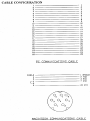
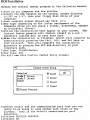
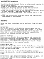
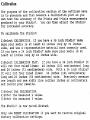
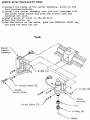
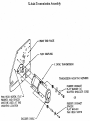
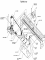
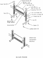
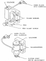
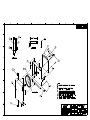
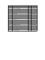
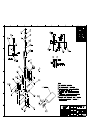
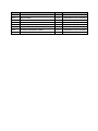
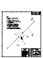
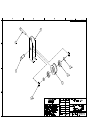
Technical Bulletins
Studio 7
TABLE OF CONTENTS
Blue Logic Board Reset
Dimensional Calibration
Green Logic Board Reset
Plotter Port Test
Poor Cut Quality
Power Supply Test
Programming Parameters
Tracking
Troubleshooting Error Conditions
Windows Control Center Installation
Y-Axis Belt Tension
Technical Bulletin
Memory Reset/Studio 7
The following procedure pertains to the “Blue Logic Board” for the Studio 7.
Sometimes, clearing the memory of the Studio 7 will solve many problems totally
unrelated to the memory. The following procedure will reset the plotter to factory
defaults and will dump anything that might be causing the plotter to act differently
than expected.
1. Move the carriage to the left end plate.
2. Turn the Studio 7 off and unplug from power source.
3. Remove the row of screws across the front and the back of plotter.
4. Lift plotter off bottom pan and lay on its top on a flat surface.
5. On the main logic board, locate JP2, which is marked clr/run.
6. Jumper the left and middle posts together.
7. Turn machine on.
8. Watch the carriage move to the right. Turn the machine off when the carriage
reaches the right end plate.
9. Remove the jumper from JP2.
The memory of the plotter is now reset to factory defaults.
Technical Bulletin
Windows Control Center Install/Studio 7
The following installation instructions pertain to versions 2.40 and earlier of the Ioline
Control Center.
1. Insert the Control Center disk into the floppy disk drive of your computer.
2. On your Windows Start Bar click on “Start” then “Run”.
3. Select “Browse”.
4. Look in your Floppy Drive A.
5. Double click on the file folder labeled “Win” or “Windows”.
6. Double click on winstall.exe to place the file on the open line of the “Run” window.
7. Click “OK”.
8. Follow the onscreen instructions for proper installation.
Technical Bulletin
Troubleshooting Error Conditions/Studio 7
The Studio 7 plotter has preprogrammed error conditions, which are defined by a particular colored light sequence emitted from the keypad
error light. The error conditions are as follows:
Error Condition
Steady Red
Description
Memory Buffer Overrun or a
Major Communication Error
Flashing Red
X-Axis Jam
Possible Cause/Solution
Replace cable.
Perform computer port test from control center
software to verify, if fails replace serial port.
Damaged RS-232 interface IC on logic board.
Perform plotter port test from control center software
to verify, if fails replace communication chip
(102822 IC, RS-232 Interface)
Defective RS-232 cable.
Defective computer serial port.
Paper jammed into grit shaft.
Ceased grit shaft bearing(s).
Ceased servo motor.
Blown transistor(s) on logic board (Position Q1–Q4)
Loose x-axis transmission motor pulley.
Damaged x-axis transmission gear assy.
Loose set screw on flex coupling.
Loose set screw on grit shaft assy.
Clear paper jam.
Replace grit shaft bearing(s).
Manually turn motor shaft; if hard to turn replace
servo motor.
Test transistor(s) w/ohm meter touching D (drain) &
S (source) leads; should read 2.23 mega ohms,
replace if reading is less.
Inspect and check pulley set screws.
Inspect gear for damaged teeth, replace damaged
gear.
Inspect and check flex coupling set screws.
Check all set screws on grit shaft assy.
Flashing Green
Y-Axis
Knife caught on edge of material causing jam.
Ceased y-axis transmission bearing(s).
Ceased servo motor.
Blown transistor(s) on logic board (Position Q5–Q8)
Damaged or striped y-axis drive belt teeth.
Damaged y-axis transmission gear assy.
Alternating
Red/Green
Plotter Language Syntax
Error or Major
Communication Error
Loose y-axis transmission motor pulley.
Wrong plotter language.
Wrong plotter driver.
Wrong data transfer protocol settings for serial port
Bad or corrupt file/Recreate file.
File sent before plotter was placed online.
Synchronization problem caused by defective servo
motor encoder.
Defective computer serial port.
Damaged RS-232 interface IC on logic board.
Clear jammed material.
Inspect bearing(s) for damage, replace y-axis
transmission bearing(s).
Manually turn motor shaft, if hard to turn replace
servo motor.
Test transistor(s) w/ohm meter touching D (drain) &
S (source) leads; should read 2.23 mega ohms,
replace if reading is less.
Inspect and replace drive belt if needed.
Inspect gear for damaged teeth, replace damaged
gear.
Inspect and check pulley set screws.
Change plotter language selected in your signmaking
software (DMPL or HPGL)
Select the driver for Studio 7 in your signmaking
software.
Check port settings from windows control panel
and/or communication settings in your signmaking
software (9600 bps, 8 data bits, 1 stop bit, Xon/Xoff
or Hardware Handshaking).
Abort file, reset plotter power to clear buffer.
Clean encoder disk, replace servo motor.
Perform computer port test from control center
software to verify, if fails replace serial port.
Perform plotter port test from control center software
to verify, if fails replace communication chip
(102822 IC, RS-232 Interface)
Technical Bulletin
Tracking/Studio 7
Good tracking is as much a factor of technique as it is one of hardware. Feeding
material off the roll, using proper acceleration and speed, optimizing your plots, and
implementing alignment guides will give you excellent tracking. If persistent tracking
problems exist, check the following:
1. Plot Optimization: Most design software provides a sorting feature within the
plotter driver setup. Sorting minimizes excessive media movement, which can
induce tracking problems.
2. Media Management: Variations in media quality will effect the performance of the
machine. Buckling vinyl can also cause skewing. Ensure the vinyl is feeding
smoothly.
3. Drive Belt Tension: A loose/worn belt or worn gear can cause the belt to slip on
the gears.
Check belts and gearing for excessive wear.
Properly adjust the
tension of all drive belts.
4. Chart Wheels: Inspect the chart wheels for uneven wear or damage.
Foreign
material like paint, paper, dirt or flat spots from prolonged chart wheels exposure
to clamp down positioning while the machine is idle will contribute to media shift.
5. Set Screws: Check the (4) grit shaft set screws, (2) in the center, (1) on each
side. Ensure the set screws are fastened properly. Set screws may loosen after
extensive use.
6. Grit Shaft: Inspect the grit shaft.
Look for any foreign material, damage, or
unusual wear.
7. Square Shaft: Check for square shaft side play.
Technical Bulletin
Programming Parameters/Studio 7
Sending a simple file of Ioline Syntax commands to the plotter can change the settings
in the Studio 7.
1. Open any Text Editor (Ex: Wordpad for Windows/Simple Text for MacIntosh) and
type in the following Ioline Syntax commands: (*=See note below)
Command
!HO1
Function
(Enter Ioline syntax, HP-GL 7475 emulation)
PT3
(Page type, custom size)
LL0,0
UR800000,22900
(Lower left)**
(Upper right, sets page size)**
SS100,100
(Scale)**
SR0
SD50,50
(Rotation, off)**
(Pen up/down delay)**
SA10,5
(Acceleration)**
KO15
KV10
(Knife offset)
(Knife overcut)**
KA45
(Knife angle)
UD
@;:
(Update)
(Exit Ioline syntax)
2. Save as: Studio7default.txt
3. Press “Starting Point” then “Pause” to place the Studio 7 online.
4. Open a modem terminal program such as “MacTerminal” for MacIntosh or
“HyperTerminal” for Windows 95/98.
5. Open the text file named Studio7default.txt and send to plotter.
6. If you need to change the rotation of the plot, select one of the following plot
rotation commands: SR0 = rotation off, SR1 = 90 degrees clockwise (CW), SR2 =
180 degrees CW, SR3 = 270 degrees CW.
*The above parameters, except for the page size, are the default values for a 24-inch Studio7.
The page size has an X-axis value of 800 inches.
These numbers can be changed to reflect
different needs. For example, to set up the page size for the Studio 7 36" cutter, change the
UR800000,22900 to UR800000,34960.
**Note that all zero values following the two-letter codes are zeros, not Ohs.
Technical Bulletin
Power Supply Test /Studio 7
Follow this procedure to test the power supply:
1.
Turn off Studio 7 and unplug.
2.
Remove the bottom pan screws and remove the pan from the plotter.
3.
Lay plotter upside down and inspect power supply for burn marks. If it is
damaged replacement is required. If power supply looks normal, continue with
test.
4.
Plug in plotter and turn it on.
5.
Using a voltmeter, check the following settings. Note: The power supply connector
color refers to the color of the wire. The connectors J-3 and J-5 are on the logic board.
6.
Insert the black (negative) test lead into the black connector (J-3) and the red
(positive) test lead into the yellow connector. The voltmeter reading should be
+33 volts +/- 5%.
7.
Insert the black test lead into the black connector (J-3) and the red test lead into
the white connector. The voltmeter reading should be +14 volts +/- 5%.
8.
Insert the black test lead into the black connector (J-3) and the red test lead into
the green connector. The voltmeter reading should be -12 volts +/- 5%.
9.
Insert the black test lead into the black connector (J-3) and the red test lead into
the blue connector. The voltmeter reading should be +12 volts +/- 5%.
10.
Insert the black test lead into the black connector (J-3) and the red test lead into
the red connector. The voltmeter reading should be +5 volts +/- 5%.
11.
Insert the black test lead into the black connector (J-5) and the red test lead into
the red connector. The voltmeter reading should be +20 volts +/- 5%.
Technical Bulletin
Poor Cut Quality/Studio 7
The most common symptom with any cutting equipment is the report of poor cut
quality. The Studio7 is designed to give users years. Broken or defective blades cause
the highest number of technical assistance inquiries to IOLINE. The naked eye cannot
detect the broken blade. The following page helps illustrate the proper installation of a
new knife blade. Also:
1. Before you begin any troubleshooting procedure, a quick inspection of the chart
tape can give clues to the origin of the cut quality problem. If the chart tape has
tracks in it or is shredded, the operator has a history of cutting too deep.
CUTTING TOO DEEP ALWAYS RESULTS IN A BROKEN BLADE. Replace the blade
and chart tape. We highly encourage testing the cut now to determine cut quality.
2. A loose carriage or linear slide on the knife assy can cause wavy lines.
switching to the Banner Adapter to help isolate the cause.
Try
3. Check the blade offsets in the Studio Control Center (see chapter 4). Make sure
the OFFSET matches the blade requirements. A 45-degree blade requires a .015
degree offset, a 60-degree blade needs a .047 degrees offset and so forth. Note:
Remember blade specifications do not exactly reflect the blade. A blade offset may vary
.002 from the stated offset on the box. Users must sometimes experiment to gain the best
cut with a particular knife.
4. Weights are used to increase force on the knife assembly. Additional force can
help cut reflective or sandblast material.
Vinyl does not need additional force.
Additional weight cannot correct a bad cut caused by a broken blade.
Technical Bulletin
Plotter Port Test/Studio 7
If you do not have the loop-back diagnostic module, complete the following steps to
test the plotter's serial port:
1. Turn off the Studio 7.
2. Remove the serial cable from the back of the plotter.
3. Using paperclips or short lengths of wire, jumper pins 2 to 3 and 4 to 5. Make
sure you get the wires in far enough to make a good connection. The pinholes are
labeled on the plotters serial port hardware. The top row is 1 through 13, from
right to left, so the pins to jumper are:
13
12
25
11
24
10
23
9
22
8
21
7
20
6
19
5
18
4
17
3
16
2
15
1
14
4. Turn on the Studio 7 while you hold down the “Test Cut” key on the keypad.
Continue holding down “Test Cut” key until Studio 7 beeps and the light flashes
three times. This places the plotter in the serial diagnostic mode.
5. Press any “Arrow” key on the plotter keypad. This emulates the transmitting and
receiving of characters. The Studio 7 should beep and the light should flash each
time an “Arrow” key is pressed.
6. Turn off the Studio 7 after the test. This will take the plotter out of the serial
diagnostic mode.
7. Remove the jumpers from the serial port.
If this test passes, then the serial port of the plotter is communicating properly.
Technical Bulletin
Memory Reset/Studio 7
The following procedure pertains to the “Green Logic Board” for the Studio 7.
Sometimes, clearing the memory of the Studio 7 will solve many problems totally
unrelated to the memory. The following procedure will reset the plotter to factory
defaults and will dump anything that might be causing the plotter to act differently
than expected.
1.
Move the carriage to the left end plate.
2.
Turn plotter off and unplug from power source.
3.
Remove the row of screws across the front and the back of plotter.
4.
Lift plotter off bottom pan and lie on its top on a flat surface.
5.
There is a flat, round, silver battery on the board. Remove the battery as you
slightly lift the tab that is holding it in place.
6.
Once the battery is removed, press the tab that held the battery in place until it
touches the surface below.
7.
Replace the battery.
8.
Next to the battery is JP4, labeled Run / ClrMem. Remove the Jumper from JP4
and move it to the right and center posts.
9.
Move the carriage to the left side of the plotter and turn the plotter on. Watch
the carriage move to the right. Turn the machine off when the carriage reaches
the right end plate.
10.
Replace the Jumper on the left and center posts.
The memory of the plotter is now reset to factory defaults.
Technical Bulletin
Dimensional Calibration/Studio 7
The purpose of calibration is to heighten the dimensional accuracy of the x-axis and yaxis measurements produced by your Studio 7 Signcutter.
To calibrate your Studio 7 Signcutter:
1.
Turn on the Studio 7.
2.
On the Studio 7 keypad press “Starting Point” and then “Pause” to place the
Studio 7 online.
3.
From your computer open the Ioline Control Center software that was originally
provided with your machine.
4.
From the main menu select “Calibrate” then “Calibrate Plotter”.
The “Set
Calibration” window should appear.
5.
Before calibrating, reset your Studio 7's “Calibration Setting” to its factory
default (1.0000), click on “Reset Calibration”.
6.
Install media large enough for the calibration plot. See table below:
7.
Click on “Calibration Plot” to plot the stored calibration plot. Your Studio 7 will
plot a rectangle. See the table below for the size of the rectangle.
8.
Measure the lines precisely to 3 decimal places. Average the measured x and y
lines of the rectangle. The averaged values are the measured values you will
enter into measured fields of the “Calibration Plot” window.
9.
Accurately enter the measured values in the fields labeled “Measured”.
10.
Click on “Set Calibration”.
11.
Your Studio 7 will calibrate itself, and the new “Calibration Setting” will be
displayed.
12.
Click on “Done” when you are finished.
Calibration Table
Model
Studio 7 36
Studio 7 24
Minimum Media
X-Axis
Y-Axis
42” x 40”
40“
28”
107 cm x 102 cm
101 cm
71 cm
42” x 24”
40“
20”
107 cm x 61 cm
101 cm
51 cm
Technical Bulletin
Y-axis Belt Tension/Studio 7
1. Gently slide the tool carriage to the right end plate.
2. Gently pull on the middle of the tool carriage belt using a spring scale that
measures in ounces, grams or both. Exert 300 to 420 (10.5 to 14.8 ounces) to
the belt deflecting the belt approximately .5 inches from its natural position.
3. To gain access to the y-axis belt tensioner, remove the left end cover. The belt
tensioner is located directly below the ribbon cartridge assembly.
4. Adjust the belt tension screw (9/64” Allen) until you achieve 300 to 420 (10.5 to
14.8 ounces) tension at .5 inch deflection from the belts natural position.
COMPONENT
101051-02
103789
104287
102394
100127
103655
100126
100128
102616
101864
101865
103790
103206
103523
102945
103144
102382
104048
103494
103792
104381
104293
102034
104291
104292
101798
101062
104471
102419
103207
104047
104481
103826
100846
102892
102897
102894
100279
100453
100108
102424
103632
102889
104029
102397
100316
102421
102959
COMP_DESC
LABOR, FRAME-UP
PLATEN, FRONT, FCC
PCB ASSY, MEGABUFFER, TESTED
TRAVERSE ASSY, 38"
O-RING, .487 ID X .103
O-RING, .426 ID X .070
O-RING, .364 ID X .070
O-RING, .539 ID X .210
SHAFT, SQUARE, 7/16 SQ X 39.05 LG
CHART WHEEL ASSY, LEFT, TWO SPRING
CHART WHEEL ASSY, RIGHT, TWO SPRING
PLATEN, REAR, FCC
PLATE, END, RIGHT, 5000, PLAT WHT
TRANS ASSY, Y-DRIVE, 1000 CT
GROMMET, VIB. DAMP., 0.563 OD, 0.21
SPACER, .166X.250X.312, ALUM
BELT ASSY, Y-DRIVE
COVER ASSY, RIGHT TOP
TRANS ASSY, X-DRIVE, 1000 CT
TAB, MTG, RIGHT FRONT, FCC
BUSHING, SQUARE SHAFT
SPACER, #10 X .312 X .50, SS
ARM, CHART HOLD LIFTER
SPRING, EXTENSION
LEVER, CHART HOLD ARM
BOTTOM PAN ASSY, LONG
TAPE, CUSHION, PEN, .437 WD
TAPE, UHMW, .43 WIDE
GRIT SHAFT ASSY, X AXIS DRIVE
PLATE, END, LEFT, 5000, PLAT WHT
CARRIAGE ASSY, STUDIO 7
CARTRIDGE ASSY, METAL
TENSIONER ASSY
CABLE ASSY, 4000, AC POWER
CABLE ASSY, SERVO MOTOR
CABLE ASSY, 34 PIN COND
CABLE ASSY, 10 PIN COND
CONN, CABLE CLIP
FAN, COOLING, 110V
SPACER, #8 CLR X 7/16 X 1/4 RND
POWER SUPPLY ASSY
CABLE ASSY, 5000 DC POWER
CABLE ASSY, RECTIFIER
PCB ASSY, STUDIO 7 LOGIC BOARD, TES
PLATE, MTG, LOGIC PCB
BEARING, BALL, .25ID, .625OD, .196
PIN, .249 DIA, 1.00 LG
PIN, .249 DIA, 1.50 LG
PARENT
104060
104060
104060
104060
104060
104060
104060
104060
104060
104060
104060
104060
104060
104060
104060
104060
104060
104060
104060
104060
104060
104060
104060
104060
104060
104060
104060
104060
104060
104060
104060
104060
104060
104060
104060
104060
104060
104060
104060
104060
104060
104060
104060
104060
104060
104060
104060
104060
PARNT_DESC
CHSY ASSY, S7
CHSY ASSY, S7
CHSY ASSY, S7
CHSY ASSY, S7
CHSY ASSY, S7
CHSY ASSY, S7
CHSY ASSY, S7
CHSY ASSY, S7
CHSY ASSY, S7
CHSY ASSY, S7
CHSY ASSY, S7
CHSY ASSY, S7
CHSY ASSY, S7
CHSY ASSY, S7
CHSY ASSY, S7
CHSY ASSY, S7
CHSY ASSY, S7
CHSY ASSY, S7
CHSY ASSY, S7
CHSY ASSY, S7
CHSY ASSY, S7
CHSY ASSY, S7
CHSY ASSY, S7
CHSY ASSY, S7
CHSY ASSY, S7
CHSY ASSY, S7
CHSY ASSY, S7
CHSY ASSY, S7
CHSY ASSY, S7
CHSY ASSY, S7
CHSY ASSY, S7
CHSY ASSY, S7
CHSY ASSY, S7
CHSY ASSY, S7
CHSY ASSY, S7
CHSY ASSY, S7
CHSY ASSY, S7
CHSY ASSY, S7
CHSY ASSY, S7
CHSY ASSY, S7
CHSY ASSY, S7
CHSY ASSY, S7
CHSY ASSY, S7
CHSY ASSY, S7
CHSY ASSY, S7
CHSY ASSY, S7
CHSY ASSY, S7
CHSY ASSY, S7
100555
100827
100152
100016
103876
100079
103908
100111
104007
101581
100099
103772
101540
100056
100095
100020
104013
100087
100277
100045
104180
104337
102321
102159
ADAPTER, BEARING, X-AXIS DRIVE
RETAINER BEARING, GRIT SHAFT, SERVO
COUPLING, ASSY, FLEX
SCREW #4-40, .875 LG, PHP SEMS
PIN, DOWEL, .125 X .75 LG
SPACER, #4, .50 LG, NYLON
SCREW #8-32, .50 LG, PHP SEMS
SPACER, .254ID, .375OD, .030LG, GOL
SCREW #8-32, .312 LG, PHP SEMS
SCREW #8-32, .375 FHP, BLACK
WSHR, #10, .875OD, .06TH, FLAT
SCREW #10-32, .625 LG, SHC, NYLOC
SCREW #10-24, 1.25 LG, PH SQ DR
SCREW #10-24, .75 LG, PH SQ DR
WSHR, #10, LOCK, EXT STAR
SCREW #6-32, .187 LG, PHP
NUT, #8-32, KEP
WSHR, #8, LOCK, EXT
TYRAP, .1 IN X 3 IN
SCREW #8-32, 2.25 LG, PHP
SCREW, #8, .50 LG, SLF TAP, PHP, SE
SCREW #4-40, .375 PHP, SEMS
SCREW #10-32, .25 DIA, .25 LG, SH S
WSHR, .250ID, .500OD, .0626THK, FLA
104060
104060
104060
104060
104060
104060
104060
104060
104060
104060
104060
104060
104060
104060
104060
104060
104060
104060
104060
104060
104060
104060
104060
104060
CHSY ASSY, S7
CHSY ASSY, S7
CHSY ASSY, S7
CHSY ASSY, S7
CHSY ASSY, S7
CHSY ASSY, S7
CHSY ASSY, S7
CHSY ASSY, S7
CHSY ASSY, S7
CHSY ASSY, S7
CHSY ASSY, S7
CHSY ASSY, S7
CHSY ASSY, S7
CHSY ASSY, S7
CHSY ASSY, S7
CHSY ASSY, S7
CHSY ASSY, S7
CHSY ASSY, S7
CHSY ASSY, S7
CHSY ASSY, S7
CHSY ASSY, S7
CHSY ASSY, S7
CHSY ASSY, S7
CHSY ASSY, S7
COMPONENT
COMP_DESC
101051-01 LABOR, SUBASSY
104045
COVER, RIGHT TOP
104046
BRACKET, REAR PANEL
100305
POWER ENTRY MODULE, W/FUSEHOLDER
100830
COVER, RECEPTACLE
104093
CABLE ASSY, REAR PANEL
100121
JACK SOCKET KIT, #4-40
100247
CONN, TERMINAL, RING, #8, 22-16 GA
100300
FUSE, 2A, 250V, 3AG S.B.
103966
PCB ASSY, KEYPAD
104006
SWITCH ASSY, STUDIO 7 KEYPAD
104049
BRACKET, SWITCH
104077
MEMBRANE SWITCH, STUDIO 7
100191
WIRE 18 GA ST GRN X 10 IN UL 1007
104015
ADAPTER, KNOB SHAFT, .125/.250
103163
BEEPER ASSY
104014
KNOB, BLACK, .25 SHAFT
106413
KNOB, BLACK, .6 X .77 OD, .25 SHAFT
103740
TAPE, FOAM, .5 IN, .025 THICK
104012
NUT, #6-32, KEP
104011
NUT, #4-40, KEP
100014
SCREW #4-40, .375 LG, PHP
PARENT
104048
104048
104048
104048
104048
104048
104048
104048
104048
104048
104048
104048
104048
104048
104048
104048
104048
104048
104048
104048
104048
104048
PARNT_DESC
COVER ASSY, RIGHT TOP
COVER ASSY, RIGHT TOP
COVER ASSY, RIGHT TOP
COVER ASSY, RIGHT TOP
COVER ASSY, RIGHT TOP
COVER ASSY, RIGHT TOP
COVER ASSY, RIGHT TOP
COVER ASSY, RIGHT TOP
COVER ASSY, RIGHT TOP
COVER ASSY, RIGHT TOP
COVER ASSY, RIGHT TOP
COVER ASSY, RIGHT TOP
COVER ASSY, RIGHT TOP
COVER ASSY, RIGHT TOP
COVER ASSY, RIGHT TOP
COVER ASSY, RIGHT TOP
COVER ASSY, RIGHT TOP
COVER ASSY, RIGHT TOP
COVER ASSY, RIGHT TOP
COVER ASSY, RIGHT TOP
COVER ASSY, RIGHT TOP
COVER ASSY, RIGHT TOP
COMPONENT
100238
100260
100335
100336
100342
100343
100344
100346
100349
100350
100357
100361
100364
100371
100373
100378
100381
100404
100405
100439
101353
101356
101357
101360
101376
102064
102441
102445
102450
102465
102796
102797
102798
102799
102800
102801
102804
102805
102807
102808
102809
102810
102811
102812
102813
102814
102816
102817
COMP_DESC
CONN, SHUNT, 2 PIN
CONN, HDR, 10 PIN, 2 X 5, MALE
RES, 100 OHM, 5%, 1/2W
RES, 1K OHM, 5%, 1/4W
RES, 220 OHM, 5%, 1/4W
RES, 2.2K OHM, 5%, 1/4W
RES, 270 OHM, 5%, 1/4W
RES, 33 OHM, 5%, 1/4 W
RES, 4.7K OHM, 5%, 1/4 W
RES, 510 OHM, 5%, 1/4 W
CAP, CERAMIC, MONO, .1UF, 50V, .2 L
CAP, CERAMIC, MONO, 100PF, 50V, .1
CAP, CERAMIC, MONO, 47PF, 50V, .1 L
TRANSISTOR, TIP 115 (CAN SUB 117)
TRANSISTOR, 2N4410, "MOTOROLA ONLY
LED, RED
DIODE, 1N4148
IC, 74LS245
IC, 74LS273
SOCKET, IC, 20 PIN DIP, .1 X .3
CAP, ELEC, ALUM, 10,000UF, 25V (SNA
RES ARRAY, 4.7K OHM, SIP PU, 10 PIN
RES ARRAY, 270 OHM, SIP PU, 10 PIN,
CONN, HDR, 3 PIN, 1 X 3, .1 SP, GO
TAPE, FOAM DOUBLE COAT, .5 IN
RES ARRAY, 1K OHM, SIP PU, 10 PIN,
CAP, TANT, 10UF, 15V, .1SP
IC, NVRAM CTLR, DS1210 CMOS, (BAT
CAP, CERAMIC, MONO, 22PF, 50V, .1 L
TRANSISTOR, MPSA06, 80V, 500MA, TOHOLDER, BATTERY, .91DIA, .12THK
CAP, ELEC, TANT, 10UF, 25V, .1 LEAD
CAP, CERAMIC, MONO, .47UF, 50V, .2
DIODE, ZENER, 1N5228B, 3.9V
CONN, HDR, 5 PIN, 1 X 5, .156 SP, W
CONN, HDR, 8 PIN, 1 X 8, .156 SP,
CONN, HDR, 34 PIN, 2 X 17
CONN, HDR, 64 PIN, 2 X 32
TRANSISTOR, IRF540 FET TO-220
RES, 1.0 OHM, 5%, 1/4W
RES, 365 OHM, 1%, 1/4W
RES, 360 OHM, 5%, 1/4W
RES, 1.1 OHM, 5%, 1/4W
RES, 12.7K OHM, 1%, 1/4W
RES, 4.7 OHM, 5%, 1/4W
RES, 360K OHM, 5%, 1/4W
RES, 270K OHM, 5%, 1/4W
SOCKET, IC, 68 PIN, PLCC, WO/WIRE B
PARENT
103982
103982
103982
103982
103982
103982
103982
103982
103982
103982
103982
103982
103982
103982
103982
103982
103982
103982
103982
103982
103982
103982
103982
103982
103982
103982
103982
103982
103982
103982
103982
103982
103982
103982
103982
103982
103982
103982
103982
103982
103982
103982
103982
103982
103982
103982
103982
103982
PARNT_DESC
PCB ASSY, 80188 MOTHER BOARD
PCB ASSY, 80188 MOTHER BOARD
PCB ASSY, 80188 MOTHER BOARD
PCB ASSY, 80188 MOTHER BOARD
PCB ASSY, 80188 MOTHER BOARD
PCB ASSY, 80188 MOTHER BOARD
PCB ASSY, 80188 MOTHER BOARD
PCB ASSY, 80188 MOTHER BOARD
PCB ASSY, 80188 MOTHER BOARD
PCB ASSY, 80188 MOTHER BOARD
PCB ASSY, 80188 MOTHER BOARD
PCB ASSY, 80188 MOTHER BOARD
PCB ASSY, 80188 MOTHER BOARD
PCB ASSY, 80188 MOTHER BOARD
PCB ASSY, 80188 MOTHER BOARD
PCB ASSY, 80188 MOTHER BOARD
PCB ASSY, 80188 MOTHER BOARD
PCB ASSY, 80188 MOTHER BOARD
PCB ASSY, 80188 MOTHER BOARD
PCB ASSY, 80188 MOTHER BOARD
PCB ASSY, 80188 MOTHER BOARD
PCB ASSY, 80188 MOTHER BOARD
PCB ASSY, 80188 MOTHER BOARD
PCB ASSY, 80188 MOTHER BOARD
PCB ASSY, 80188 MOTHER BOARD
PCB ASSY, 80188 MOTHER BOARD
PCB ASSY, 80188 MOTHER BOARD
PCB ASSY, 80188 MOTHER BOARD
PCB ASSY, 80188 MOTHER BOARD
PCB ASSY, 80188 MOTHER BOARD
PCB ASSY, 80188 MOTHER BOARD
PCB ASSY, 80188 MOTHER BOARD
PCB ASSY, 80188 MOTHER BOARD
PCB ASSY, 80188 MOTHER BOARD
PCB ASSY, 80188 MOTHER BOARD
PCB ASSY, 80188 MOTHER BOARD
PCB ASSY, 80188 MOTHER BOARD
PCB ASSY, 80188 MOTHER BOARD
PCB ASSY, 80188 MOTHER BOARD
PCB ASSY, 80188 MOTHER BOARD
PCB ASSY, 80188 MOTHER BOARD
PCB ASSY, 80188 MOTHER BOARD
PCB ASSY, 80188 MOTHER BOARD
PCB ASSY, 80188 MOTHER BOARD
PCB ASSY, 80188 MOTHER BOARD
PCB ASSY, 80188 MOTHER BOARD
PCB ASSY, 80188 MOTHER BOARD
PCB ASSY, 80188 MOTHER BOARD
102818
102821
102822
102823
102824
102825
102829
102830
102831
102837
102883
102988
103039
103040
103042
103083
103154
103155
103158
103261
103293
103397
103418
103724
103725
103928
103938
103941
103946
103995
103996
103997
103998
103999
104020
104594
103503
102878
102963
101374
103868
104560
100120
104337
101871
101601
103153
IC, 74ALS08
IC, O.C. DRIVER, ULN2064
IC, RS232 INTER, 145406
IC, D/A CONV, DAC0808
IC, 4-CHAN, A/D CONV, ADC0844
TEST POINT, TURRET-SWAGE, .094 HOLE
IC, DUAL H-BRIDGE SW, UDN2993B
IC, PAL, PROG 16L8, SERVOPEN
IC, OP W/COMP, LM392
CAP, CERAMIC, MONO, .01UF, 50V, .2
HEAT SINK, TO-220, 1.55 X .375, PC
RES, 2.2 OHM, 5%, 1/4W
IC, MICROPROCESSOR, 80188-12, PLCC
CRYSTAL, 24.576 MHZ
IC, RAM, STATIC, 32KX8, 62256LP, 12
FERRITE BEAD, 0-40 MHZ, .21 OD X .4
CAP, CERAMIC, MONO, 220PF, 25V, .2
INDUCTOR, 8.2MH, RES.FREQ. 40 MHZ,
CONN, HDR, 5 PIN, 1 X 5, .100 SP, W
IC, SN754410-NE, DRIVER, QUADRUPLE
IC, HEX INVERTER, 74ACT04
SOCKET, IC, 32 PIN DIP, .1 X .6 MAC
DIODE, ZENER, 1N5230B, 4.7V
RES, 4.7 OHM, 5%, 1W
RES, 680 OHM, 5%, 1/4W
RES, 33 OHM, 5%, 1/2W
ZIPLOCK BAG, STATIC, 12 X 16
IC, 74ALS573
RES, 47 OHM, 5%, 1/2W
RES, 1K OHM, 1%, 1/4W
DIODE, 1N5818
RES, 2K OHM, 1%, 1/4W
FET, VN1OLM
DIODE, 1N5247
CAP,DISC/MONO,100PF,5% NPO/COG,50V,
RES, 1.0 OHM, 5%, 1/2 W
PCB, 80188-FCC MOTHER BOARD
INSULATOR, FOR TO220, .600 SP
HEAT SINK, FOR TO220, .600 SP
WIRE 20 GA SOLID TINNED, UL 1007/1
TUBE, TEFLON, CLEAR, 24 GA
SCREW #4-40, .250 PHP, SEMS
WSHR, SHLDER, #4 X .031, NYLON
SCREW #4-40, .375 PHP, SEMS
WSHR, #4, FLAT, STEEL
NUT, #4-40, HEX, THIN NYLOCK
WSHR, .120ID, .180OD, .032TH, FLAT,
103982
103982
103982
103982
103982
103982
103982
103982
103982
103982
103982
103982
103982
103982
103982
103982
103982
103982
103982
103982
103982
103982
103982
103982
103982
103982
103982
103982
103982
103982
103982
103982
103982
103982
103982
103982
103982
103982
103982
103982
103982
103982
103982
103982
103982
103982
103982
PCB ASSY, 80188 MOTHER BOARD
PCB ASSY, 80188 MOTHER BOARD
PCB ASSY, 80188 MOTHER BOARD
PCB ASSY, 80188 MOTHER BOARD
PCB ASSY, 80188 MOTHER BOARD
PCB ASSY, 80188 MOTHER BOARD
PCB ASSY, 80188 MOTHER BOARD
PCB ASSY, 80188 MOTHER BOARD
PCB ASSY, 80188 MOTHER BOARD
PCB ASSY, 80188 MOTHER BOARD
PCB ASSY, 80188 MOTHER BOARD
PCB ASSY, 80188 MOTHER BOARD
PCB ASSY, 80188 MOTHER BOARD
PCB ASSY, 80188 MOTHER BOARD
PCB ASSY, 80188 MOTHER BOARD
PCB ASSY, 80188 MOTHER BOARD
PCB ASSY, 80188 MOTHER BOARD
PCB ASSY, 80188 MOTHER BOARD
PCB ASSY, 80188 MOTHER BOARD
PCB ASSY, 80188 MOTHER BOARD
PCB ASSY, 80188 MOTHER BOARD
PCB ASSY, 80188 MOTHER BOARD
PCB ASSY, 80188 MOTHER BOARD
PCB ASSY, 80188 MOTHER BOARD
PCB ASSY, 80188 MOTHER BOARD
PCB ASSY, 80188 MOTHER BOARD
PCB ASSY, 80188 MOTHER BOARD
PCB ASSY, 80188 MOTHER BOARD
PCB ASSY, 80188 MOTHER BOARD
PCB ASSY, 80188 MOTHER BOARD
PCB ASSY, 80188 MOTHER BOARD
PCB ASSY, 80188 MOTHER BOARD
PCB ASSY, 80188 MOTHER BOARD
PCB ASSY, 80188 MOTHER BOARD
PCB ASSY, 80188 MOTHER BOARD
PCB ASSY, 80188 MOTHER BOARD
PCB ASSY, 80188 MOTHER BOARD
PCB ASSY, 80188 MOTHER BOARD
PCB ASSY, 80188 MOTHER BOARD
PCB ASSY, 80188 MOTHER BOARD
PCB ASSY, 80188 MOTHER BOARD
PCB ASSY, 80188 MOTHER BOARD
PCB ASSY, 80188 MOTHER BOARD
PCB ASSY, 80188 MOTHER BOARD
PCB ASSY, 80188 MOTHER BOARD
PCB ASSY, 80188 MOTHER BOARD
PCB ASSY, 80188 MOTHER BOARD
COMPONENT
100336
100342
100343
100344
100349
100350
100353
100361
100364
100371
100378
100381
100404
100405
100436
100438
100439
100917
101356
101360
101374
102064
102450
102797
102798
102800
102801
102805
102806
102808
102809
102810
102811
102812
102813
102814
102816
102817
102821
102822
102823
102824
102825
102829
102830
102831
102988
103039
COMP_DESC
RES, 1K OHM, 5%, 1/4W
RES, 220 OHM, 5%, 1/4W
RES, 2.2K OHM, 5%, 1/4W
RES, 270 OHM, 5%, 1/4W
RES, 4.7K OHM, 5%, 1/4 W
RES, 510 OHM, 5%, 1/4 W
RES ARRAY, 3.3K OHM, SIP PU, 6 PIN,
CAP, CERAMIC, MONO, 100PF, 50V, .1
CAP, CERAMIC, MONO, 47PF, 50V, .1 L
TRANSISTOR, TIP 115 (CAN SUB 117)
LED, RED
DIODE, 1N4148
IC, 74LS245
IC, 74LS273
SOCKET, IC, 8 PIN DIP, .1 X .3
SOCKET, IC, 16 PIN DIP, .1 X .3
SOCKET, IC, 20 PIN DIP, .1 X .3
IC, 74LS157
RES ARRAY, 4.7K OHM, SIP PU, 10 PIN
CONN, HDR, 3 PIN, 1 X 3, .1 SP, GO
WIRE 20 GA SOLID TINNED, UL 1007/1
RES ARRAY, 1K OHM, SIP PU, 10 PIN,
CAP, CERAMIC, MONO, 22PF, 50V, .1 L
CAP, ELEC, TANT, 10UF, 25V, .1 LEAD
CAP, CERAMIC, MONO, .47UF, 50V, .2
CONN, HDR, 5 PIN, 1 X 5, .156 SP, W
CONN, HDR, 8 PIN, 1 X 8, .156 SP,
CONN, HDR, 64 PIN, 2 X 32
CONN, HDR, 2 PIN, 1 X 2, .1 SP
RES, 1.0 OHM, 5%, 1/4W
RES, 365 OHM, 1%, 1/4W
RES, 360 OHM, 5%, 1/4W
RES, 1.1 OHM, 5%, 1/4W
RES, 12.7K OHM, 1%, 1/4W
RES, 4.7 OHM, 5%, 1/4W
RES, 360K OHM, 5%, 1/4W
RES, 270K OHM, 5%, 1/4W
SOCKET, IC, 68 PIN, PLCC, WO/WIRE B
IC, O.C. DRIVER, ULN2064
IC, RS232 INTER, 145406
IC, D/A CONV, DAC0808
IC, 4-CHAN, A/D CONV, ADC0844
TEST POINT, TURRET-SWAGE, .094 HOLE
IC, DUAL H-BRIDGE SW, UDN2993B
IC, PAL, PROG 16L8, SERVOPEN
IC, OP W/COMP, LM392
RES, 2.2 OHM, 5%, 1/4W
IC, MICROPROCESSOR, 80188-12, PLCC
PARENT
104523
104523
104523
104523
104523
104523
104523
104523
104523
104523
104523
104523
104523
104523
104523
104523
104523
104523
104523
104523
104523
104523
104523
104523
104523
104523
104523
104523
104523
104523
104523
104523
104523
104523
104523
104523
104523
104523
104523
104523
104523
104523
104523
104523
104523
104523
104523
104523
PARNT_DESC
PCB ASSY, 80188 LOGIC BOARD
PCB ASSY, 80188 LOGIC BOARD
PCB ASSY, 80188 LOGIC BOARD
PCB ASSY, 80188 LOGIC BOARD
PCB ASSY, 80188 LOGIC BOARD
PCB ASSY, 80188 LOGIC BOARD
PCB ASSY, 80188 LOGIC BOARD
PCB ASSY, 80188 LOGIC BOARD
PCB ASSY, 80188 LOGIC BOARD
PCB ASSY, 80188 LOGIC BOARD
PCB ASSY, 80188 LOGIC BOARD
PCB ASSY, 80188 LOGIC BOARD
PCB ASSY, 80188 LOGIC BOARD
PCB ASSY, 80188 LOGIC BOARD
PCB ASSY, 80188 LOGIC BOARD
PCB ASSY, 80188 LOGIC BOARD
PCB ASSY, 80188 LOGIC BOARD
PCB ASSY, 80188 LOGIC BOARD
PCB ASSY, 80188 LOGIC BOARD
PCB ASSY, 80188 LOGIC BOARD
PCB ASSY, 80188 LOGIC BOARD
PCB ASSY, 80188 LOGIC BOARD
PCB ASSY, 80188 LOGIC BOARD
PCB ASSY, 80188 LOGIC BOARD
PCB ASSY, 80188 LOGIC BOARD
PCB ASSY, 80188 LOGIC BOARD
PCB ASSY, 80188 LOGIC BOARD
PCB ASSY, 80188 LOGIC BOARD
PCB ASSY, 80188 LOGIC BOARD
PCB ASSY, 80188 LOGIC BOARD
PCB ASSY, 80188 LOGIC BOARD
PCB ASSY, 80188 LOGIC BOARD
PCB ASSY, 80188 LOGIC BOARD
PCB ASSY, 80188 LOGIC BOARD
PCB ASSY, 80188 LOGIC BOARD
PCB ASSY, 80188 LOGIC BOARD
PCB ASSY, 80188 LOGIC BOARD
PCB ASSY, 80188 LOGIC BOARD
PCB ASSY, 80188 LOGIC BOARD
PCB ASSY, 80188 LOGIC BOARD
PCB ASSY, 80188 LOGIC BOARD
PCB ASSY, 80188 LOGIC BOARD
PCB ASSY, 80188 LOGIC BOARD
PCB ASSY, 80188 LOGIC BOARD
PCB ASSY, 80188 LOGIC BOARD
PCB ASSY, 80188 LOGIC BOARD
PCB ASSY, 80188 LOGIC BOARD
PCB ASSY, 80188 LOGIC BOARD
103040
103042
103083
103155
103158
103261
103397
103418
103725
103798
103941
104318
104528
104531
104532
104533
104534
104535
104536
104537
104538
104539
104540
104541
104542
102807
104545
100365
103938
104581
104594
104885
104614
101353
105858
104522
101601
104337
101397
CRYSTAL, 24.576 MHZ
IC, RAM, STATIC, 32KX8, 62256LP, 12
FERRITE BEAD, 0-40 MHZ, .21 OD X .4
INDUCTOR, 8.2MH, RES.FREQ. 40 MHZ,
CONN, HDR, 5 PIN, 1 X 5, .100 SP, W
IC, SN754410-NE, DRIVER, QUADRUPLE
SOCKET, IC, 32 PIN DIP, .1 X .6 MAC
DIODE, ZENER, 1N5230B, 4.7V
RES, 680 OHM, 5%, 1/4W
IC, ROM, EE, X24C16, XICOR
IC, 74ALS573
CONN, HDR, 2 PIN, .156 SP, W/LOCK
CONN, HDR, 2 X 5 MALE, W/LATCHES
CAP, CERAMIC, MONO, .022UF, 50V, .
CAP, CERAMIC, MONO, .1UF, 50V, .1
CAP, CERAMIC, MONO, .01UF, 50V, .1
CAP, CERAMIC, MONO, 220PF, 50V, .1
CAP, CERAMIC, MONO, .33UF, 50V, .2
IC, MICROPROCESSR, ADSP-2105
IC, 74HC32, QUAD OR, CMOS
RES, 47 OHM, 5%, 1/4 W
TRANSISTOR, P MOSFET
IC, TC4426, DUAL MOSFET DRIVER
CRYSTAL, 10.000 MHZ, HC49
DIODE, ZENER, IN5237B, 8.2V
TRANSISTOR, IRF540 FET TO-220
SOCKET, IC, 28 PIN, MACH PIN
CAP, ELEC, ALUM, 470UF, 25V, RADIAL
ZIPLOCK BAG, STATIC, 12 X 16
CONN, HDR, 2 X 17 PIN, W/EJECT
RES, 1.0 OHM, 5%, 1/2 W
HEATSINK, MACHINED
HEAT SINK, TO-220
CAP, ELEC, ALUM, 10,000UF, 25V (SNA
TRANSISTOR, MTP23P06V, PMOSFET
PCB, 80188 MOTHER BOARD
NUT, #4-40, HEX, THIN NYLOCK
SCREW #4-40, .375 PHP, SEMS
WIRE 18 GA ST BLK, 6 IN, UL 1007
104523
104523
104523
104523
104523
104523
104523
104523
104523
104523
104523
104523
104523
104523
104523
104523
104523
104523
104523
104523
104523
104523
104523
104523
104523
104523
104523
104523
104523
104523
104523
104523
104523
104523
104523
104523
104523
104523
104523
PCB ASSY, 80188 LOGIC BOARD
PCB ASSY, 80188 LOGIC BOARD
PCB ASSY, 80188 LOGIC BOARD
PCB ASSY, 80188 LOGIC BOARD
PCB ASSY, 80188 LOGIC BOARD
PCB ASSY, 80188 LOGIC BOARD
PCB ASSY, 80188 LOGIC BOARD
PCB ASSY, 80188 LOGIC BOARD
PCB ASSY, 80188 LOGIC BOARD
PCB ASSY, 80188 LOGIC BOARD
PCB ASSY, 80188 LOGIC BOARD
PCB ASSY, 80188 LOGIC BOARD
PCB ASSY, 80188 LOGIC BOARD
PCB ASSY, 80188 LOGIC BOARD
PCB ASSY, 80188 LOGIC BOARD
PCB ASSY, 80188 LOGIC BOARD
PCB ASSY, 80188 LOGIC BOARD
PCB ASSY, 80188 LOGIC BOARD
PCB ASSY, 80188 LOGIC BOARD
PCB ASSY, 80188 LOGIC BOARD
PCB ASSY, 80188 LOGIC BOARD
PCB ASSY, 80188 LOGIC BOARD
PCB ASSY, 80188 LOGIC BOARD
PCB ASSY, 80188 LOGIC BOARD
PCB ASSY, 80188 LOGIC BOARD
PCB ASSY, 80188 LOGIC BOARD
PCB ASSY, 80188 LOGIC BOARD
PCB ASSY, 80188 LOGIC BOARD
PCB ASSY, 80188 LOGIC BOARD
PCB ASSY, 80188 LOGIC BOARD
PCB ASSY, 80188 LOGIC BOARD
PCB ASSY, 80188 LOGIC BOARD
PCB ASSY, 80188 LOGIC BOARD
PCB ASSY, 80188 LOGIC BOARD
PCB ASSY, 80188 LOGIC BOARD
PCB ASSY, 80188 LOGIC BOARD
PCB ASSY, 80188 LOGIC BOARD
PCB ASSY, 80188 LOGIC BOARD
PCB ASSY, 80188 LOGIC BOARD
COMPONENT
100336
100346
100357
100404
100407
101346
102441
102798
102825
103077
103935
104254
104255
104256
104257
104258
104259
104260
104261
104262
101051-05
103884
103255
COMP_DESC
RES, 1K OHM, 5%, 1/4W
RES, 33 OHM, 5%, 1/4 W
CAP, CERAMIC, MONO, .1UF, 50V, .2 L
IC, 74LS245
IC, 74LS393
IC, 74LS574
CAP, TANT, 10UF, 15V, .1SP
CAP, CERAMIC, MONO, .47UF, 50V, .2
TEST POINT, TURRET-SWAGE, .094 HOLE
CONN, HDR, 64 PIN, 2 X 32, FEMALE
ZIPLOCK BAG, STATIC, 6 X 8
IC, PLD, PROG 16V8-15, MEGABUFFER,
IC, PLD, PROG 16V8-15, MEGABUFFER,
IC, PLD, PROG 16V8-15, MEGABUFFER,
IC, PLD, PROG 20V8-15, MEGABUFFER,
SOCKET, IC, 20 PIN ZIP, AMP 2-38200
IC, 74F139
IC, 74F112
IC, 74F712-1
IC, RAM, DYNAMIC, IMX4, 20 PIN ZIP
LABOR, TEST
PCB, MEGABUFFER FOR 5000
SPACER, ROUND, 1/4 OD, #4, 1/2 LENG
PARENT
103885
103885
103885
103885
103885
103885
103885
103885
103885
103885
103885
103885
103885
103885
103885
103885
103885
103885
103885
103885
103885
103885
103885
PARNT_DESC
PCB ASSY, MEGABUFFER, 1M RAM
PCB ASSY, MEGABUFFER, 1M RAM
PCB ASSY, MEGABUFFER, 1M RAM
PCB ASSY, MEGABUFFER, 1M RAM
PCB ASSY, MEGABUFFER, 1M RAM
PCB ASSY, MEGABUFFER, 1M RAM
PCB ASSY, MEGABUFFER, 1M RAM
PCB ASSY, MEGABUFFER, 1M RAM
PCB ASSY, MEGABUFFER, 1M RAM
PCB ASSY, MEGABUFFER, 1M RAM
PCB ASSY, MEGABUFFER, 1M RAM
PCB ASSY, MEGABUFFER, 1M RAM
PCB ASSY, MEGABUFFER, 1M RAM
PCB ASSY, MEGABUFFER, 1M RAM
PCB ASSY, MEGABUFFER, 1M RAM
PCB ASSY, MEGABUFFER, 1M RAM
PCB ASSY, MEGABUFFER, 1M RAM
PCB ASSY, MEGABUFFER, 1M RAM
PCB ASSY, MEGABUFFER, 1M RAM
PCB ASSY, MEGABUFFER, 1M RAM
PCB ASSY, MEGABUFFER, 1M RAM
PCB ASSY, MEGABUFFER, 1M RAM
PCB ASSY, MEGABUFFER, 1M RAM
COMPONENT
100343
100357
100378
100381
100393
100439
100901
101346
101356
101357
102065
102441
102457
102458
102465
102636
103963
103965
104002
104019
104021
104022
103935
102064
COMP_DESC
RES, 2.2K OHM, 5%, 1/4W
CAP, CERAMIC, MONO, .1UF, 50V, .2 L
LED, RED
DIODE, 1N4148
IC, 74LS14
SOCKET, IC, 20 PIN DIP, .1 X .3
LED, RED/GRN
IC, 74LS574
RES ARRAY, 4.7K OHM, SIP PU, 10 PIN
RES ARRAY, 270 OHM, SIP PU, 10 PIN,
CONN, HDR, 10 PIN, 2 X 5 R-ANGLE M
CAP, TANT, 10UF, 15V, .1SP
IC, 74LS299
IC, 74LS165
TRANSISTOR, MPSA06, 80V, 500MA, TOCONN, HDR, 2 PIN, 1 X 2, .1 SP, RA
SWITCH, 11 POS ROTARY, 1/8" SHAFT,
PCB, KEYPAD, STUDIO 7
IC, GAL, PROG, STUDIO 7 KEYPAD
LED, GREEN
CONN, HDR, 3 PIN, 1 X 3, .1 SP, RA
CONN, HDR, 11 PIN, 1 X 3, .1 SP, RA
ZIPLOCK BAG, STATIC, 6 X 8
RES ARRAY, 1K OHM, SIP PU, 10 PIN,
PARENT
103966-01
103966-01
103966-01
103966-01
103966-01
103966-01
103966-01
103966-01
103966-01
103966-01
103966-01
103966-01
103966-01
103966-01
103966-01
103966-01
103966-01
103966-01
103966-01
103966-01
103966-01
103966-01
103966-01
103966-01
PARNT_DESC
PCB ASSY, KEYPAD, STUDIO 7, UNTEST
PCB ASSY, KEYPAD, STUDIO 7, UNTEST
PCB ASSY, KEYPAD, STUDIO 7, UNTEST
PCB ASSY, KEYPAD, STUDIO 7, UNTEST
PCB ASSY, KEYPAD, STUDIO 7, UNTEST
PCB ASSY, KEYPAD, STUDIO 7, UNTEST
PCB ASSY, KEYPAD, STUDIO 7, UNTEST
PCB ASSY, KEYPAD, STUDIO 7, UNTEST
PCB ASSY, KEYPAD, STUDIO 7, UNTEST
PCB ASSY, KEYPAD, STUDIO 7, UNTEST
PCB ASSY, KEYPAD, STUDIO 7, UNTEST
PCB ASSY, KEYPAD, STUDIO 7, UNTEST
PCB ASSY, KEYPAD, STUDIO 7, UNTEST
PCB ASSY, KEYPAD, STUDIO 7, UNTEST
PCB ASSY, KEYPAD, STUDIO 7, UNTEST
PCB ASSY, KEYPAD, STUDIO 7, UNTEST
PCB ASSY, KEYPAD, STUDIO 7, UNTEST
PCB ASSY, KEYPAD, STUDIO 7, UNTEST
PCB ASSY, KEYPAD, STUDIO 7, UNTEST
PCB ASSY, KEYPAD, STUDIO 7, UNTEST
PCB ASSY, KEYPAD, STUDIO 7, UNTEST
PCB ASSY, KEYPAD, STUDIO 7, UNTEST
PCB ASSY, KEYPAD, STUDIO 7, UNTEST
PCB ASSY, KEYPAD, STUDIO 7, UNTEST
COMPONENT
101051-01
102902
102903
102904
102910
103450
102939
102655
102737
104008
103908
102944
103551
100091
COMP_DESC
LABOR, SUBASSY
BRACKET, TRANSMISSION, X-DRIVE
PLATE, MTG, MOTOR
PLATE, SUB, TRANSMISSION, X-DRIVE
GEAR, 33 TOOTH, 64 PITCH, 20 DEG
MOTOR, SERVO, 1000 CT ENCODER
GEAR ASSY, X-DRIVE, 165 TOOTH, 64
BEARING, FLANGE, .250ID, .500OD
SCREW #6-32, .25 LG, FHP
SCREW #8-32, .375 LG, PHP SEMS
SCREW #8-32, .50 LG, PHP SEMS
SCREW, #6-32 X .125 LG SH SET, CUP
WSHR, WAVE, .265 ID, .367 OD
WSHR, #8, FLAT, STEEL
PARENT
103494
103494
103494
103494
103494
103494
103494
103494
103494
103494
103494
103494
103494
103494
PARNT_DESC
TRANS ASSY, X-DRIVE, 1000 CT
TRANS ASSY, X-DRIVE, 1000 CT
TRANS ASSY, X-DRIVE, 1000 CT
TRANS ASSY, X-DRIVE, 1000 CT
TRANS ASSY, X-DRIVE, 1000 CT
TRANS ASSY, X-DRIVE, 1000 CT
TRANS ASSY, X-DRIVE, 1000 CT
TRANS ASSY, X-DRIVE, 1000 CT
TRANS ASSY, X-DRIVE, 1000 CT
TRANS ASSY, X-DRIVE, 1000 CT
TRANS ASSY, X-DRIVE, 1000 CT
TRANS ASSY, X-DRIVE, 1000 CT
TRANS ASSY, X-DRIVE, 1000 CT
TRANS ASSY, X-DRIVE, 1000 CT
COMPONENT
101051-01
102908
102910
103450
103527
103212
102344
102650
103528
103529
102655
100044
102737
104008
102944
102322
100087
103401
103970
103551
103973
COMP_DESC
LABOR, SUBASSY
PLATE, MTG, MOTOR, Y-DRIVE
GEAR, 33 TOOTH, 64 PITCH, 20 DEG
MOTOR, SERVO, 1000 CT ENCODER
GEAR ASSY, Y-DRIVE, 165 TOOTH, 64 P
SHAFT, Y-AXIS DRIVE
PULLEY, IDLER
BEARING .375 X .125
BRACKET, TRANSMISSION, LOWER, Y-DR
BRACKET, TRANSMISSION, UPPER, Y-DR
BEARING, FLANGE, .250ID, .500OD
SCREW #8-32, .75 PHP
SCREW #6-32, .25 LG, FHP
SCREW #8-32, .375 LG, PHP SEMS
SCREW, #6-32 X .125 LG SH SET, CUP
RING, RETAINING, E-CLIP, .125
WSHR, #8, LOCK, EXT
SPACER, #6, .312 LG, NYLON
SPACER, PRECISION, 1/8"
WSHR, WAVE, .265 ID, .367 OD
WSHR, .170 ID, .375 OD, .035TH, SS
PARENT
103523
103523
103523
103523
103523
103523
103523
103523
103523
103523
103523
103523
103523
103523
103523
103523
103523
103523
103523
103523
103523
PARNT_DESC
TRANS ASSY, Y-DRIVE, 1000 CT
TRANS ASSY, Y-DRIVE, 1000 CT
TRANS ASSY, Y-DRIVE, 1000 CT
TRANS ASSY, Y-DRIVE, 1000 CT
TRANS ASSY, Y-DRIVE, 1000 CT
TRANS ASSY, Y-DRIVE, 1000 CT
TRANS ASSY, Y-DRIVE, 1000 CT
TRANS ASSY, Y-DRIVE, 1000 CT
TRANS ASSY, Y-DRIVE, 1000 CT
TRANS ASSY, Y-DRIVE, 1000 CT
TRANS ASSY, Y-DRIVE, 1000 CT
TRANS ASSY, Y-DRIVE, 1000 CT
TRANS ASSY, Y-DRIVE, 1000 CT
TRANS ASSY, Y-DRIVE, 1000 CT
TRANS ASSY, Y-DRIVE, 1000 CT
TRANS ASSY, Y-DRIVE, 1000 CT
TRANS ASSY, Y-DRIVE, 1000 CT
TRANS ASSY, Y-DRIVE, 1000 CT
TRANS ASSY, Y-DRIVE, 1000 CT
TRANS ASSY, Y-DRIVE, 1000 CT
TRANS ASSY, Y-DRIVE, 1000 CT
COMPONENT
101051-01
103571
103572
102410
102884
101376
105562
104337
104007
104013
COMP_DESC
LABOR, SUBASSY
COVER, CARTRIDGE
CARTRIDGE, BODY
FLEX CABLE, 12 COND
PCB ASSY, CARTRIDGE
TAPE, FOAM DOUBLE COAT, .5 IN
PROTECTOR, PIN, CARTRIDGE
SCREW #4-40, .375 PHP, SEMS
SCREW #8-32, .312 LG, PHP SEMS
NUT, #8-32, KEP
PARENT
104481
104481
104481
104481
104481
104481
104481
104481
104481
104481
PARNT_DESC
CARTRIDGE ASSY, METAL
CARTRIDGE ASSY, METAL
CARTRIDGE ASSY, METAL
CARTRIDGE ASSY, METAL
CARTRIDGE ASSY, METAL
CARTRIDGE ASSY, METAL
CARTRIDGE ASSY, METAL
CARTRIDGE ASSY, METAL
CARTRIDGE ASSY, METAL
CARTRIDGE ASSY, METAL
COMPONENT
101051-01
102329
102991
103828
103221
104056
104501
102976
102620
103659
102322
102989
COMP_DESC
LABOR, SUBASSY
FRAME, CARRIAGE
SHAFT, WHEEL
WHEEL, CARRIAGE
BEARING, RADIAL FLANGE, .125ID, .3
BLOCK, CARRIAGE
PCB ASSY, CARRIAGE
SCREW #4-24, .312 LG, PHP, BLUNT PO
WAVE WASHER
WSHR, .125ID, .020TH, FLAT, NYLON
RING, RETAINING, E-CLIP, .125
SCREW #4-24, .50 LG, PHP, SELF TAP,
PARENT
104047
104047
104047
104047
104047
104047
104047
104047
104047
104047
104047
104047
PARNT_DESC
CARRIAGE ASSY, STUDIO 7
CARRIAGE ASSY, STUDIO 7
CARRIAGE ASSY, STUDIO 7
CARRIAGE ASSY, STUDIO 7
CARRIAGE ASSY, STUDIO 7
CARRIAGE ASSY, STUDIO 7
CARRIAGE ASSY, STUDIO 7
CARRIAGE ASSY, STUDIO 7
CARRIAGE ASSY, STUDIO 7
CARRIAGE ASSY, STUDIO 7
CARRIAGE ASSY, STUDIO 7
CARRIAGE ASSY, STUDIO 7
COMPONENT
101051-01
104042
104057
104059
102850
104058
104016
104041
103655
104307
104017
104103
103852
104053
103090
102974
104051
103408
104605
104132
104010
104559
104992
103726
104962
COMP_DESC
LABOR, SUBASSY
CAP, CUTTER
SPRING, COMPRESSION
SOLENOID, CUTTER
CABLE ASSY, 90 DEG MINI DIN, STRN R
NOSE, CUTTER
BEARING, DU, .312 ID, .500 LG
FOOT, CUTTER
O-RING, .426 ID X .070
HOUSING, CUTTER
LINEAR SLIDE, BALL BEARING
THUMBSCREW
RING, RETAINING, E-CLIP, 3/16
BLOCK, MOUNTING
BOOT, CABLE
HEATSHRINK, .093 DIA, CLEAR
SHAFT ASSY, CUTTER
SCREW #4-40, .50 LG FHP, BLK
SCREW #4-40, .625 LG, W/LOCK
SCREW #4-40, .156 LG, SET, NYLON TI
SCREW M3, 4 MM LG
SCREW #2-56, .3125 LG, FHP
SCREW, #2-56 X .4375 LG, FHP
TYRAP, .1 IN X 3 IN, BLACK
NUT, M2.5 X 0.45, HEX
PARENT
104050
104050
104050
104050
104050
104050
104050
104050
104050
104050
104050
104050
104050
104050
104050
104050
104050
104050
104050
104050
104050
104050
104050
104050
104050
PARNT_DESC
CUTTER ASSY, STUDIO 7
CUTTER ASSY, STUDIO 7
CUTTER ASSY, STUDIO 7
CUTTER ASSY, STUDIO 7
CUTTER ASSY, STUDIO 7
CUTTER ASSY, STUDIO 7
CUTTER ASSY, STUDIO 7
CUTTER ASSY, STUDIO 7
CUTTER ASSY, STUDIO 7
CUTTER ASSY, STUDIO 7
CUTTER ASSY, STUDIO 7
CUTTER ASSY, STUDIO 7
CUTTER ASSY, STUDIO 7
CUTTER ASSY, STUDIO 7
CUTTER ASSY, STUDIO 7
CUTTER ASSY, STUDIO 7
CUTTER ASSY, STUDIO 7
CUTTER ASSY, STUDIO 7
CUTTER ASSY, STUDIO 7
CUTTER ASSY, STUDIO 7
CUTTER ASSY, STUDIO 7
CUTTER ASSY, STUDIO 7
CUTTER ASSY, STUDIO 7
CUTTER ASSY, STUDIO 7
CUTTER ASSY, STUDIO 7
COMPONENT
101051-01
103408
104650
104605
104243
104057
104059
102850
104244
104017
104103
104245
104246
103090
104247
104135
103852
104559
104241
104010
102974
103726
COMP_DESC
LABOR, SUBASSY
SCREW #4-40, .50 LG FHP, BLK
COVER, UNWINDER
SCREW #4-40, .625 LG, W/LOCK
CAP, PEN SOLENOID
SPRING, COMPRESSION
SOLENOID, CUTTER
CABLE ASSY, 90 DEG MINI DIN, STRN R
BLOCK, PEN HOLDER
LINEAR SLIDE, BALL BEARING
THUMBSCREW
PLATE, ACTUATOR
CLAMP, PEN HOLDER
BOOT, CABLE
GAUGE, PEN HEIGHT
SCREW 5/16-18, 1.0 LG, THUMB
RING, RETAINING, E-CLIP, 3/16
SCREW #2-56, .3125 LG, FHP
NUT, M2.5 X 0.45, HEX NYLOCK
SCREW M3, 4 MM LG
HEATSHRINK, .093 DIA, CLEAR
TYRAP, .1 IN X 3 IN, BLACK
PARENT
104238
104238
104238
104238
104238
104238
104238
104238
104238
104238
104238
104238
104238
104238
104238
104238
104238
104238
104238
104238
104238
104238
PARNT_DESC
PEN HOLDER ASSY
PEN HOLDER ASSY
PEN HOLDER ASSY
PEN HOLDER ASSY
PEN HOLDER ASSY
PEN HOLDER ASSY
PEN HOLDER ASSY
PEN HOLDER ASSY
PEN HOLDER ASSY
PEN HOLDER ASSY
PEN HOLDER ASSY
PEN HOLDER ASSY
PEN HOLDER ASSY
PEN HOLDER ASSY
PEN HOLDER ASSY
PEN HOLDER ASSY
PEN HOLDER ASSY
PEN HOLDER ASSY
PEN HOLDER ASSY
PEN HOLDER ASSY
PEN HOLDER ASSY
PEN HOLDER ASSY
COMPONENT
101051-01
100943
101004
101861
101862
101863
101866
101867
COMP_DESC
LABOR, SUBASSY
WHEEL, IDLER ARM
AXLE, IDLER ARM WHEEL
PIN, IDLER ARM
SPRING, SLIDE, CHART WHEEL
SPRING, TENSION, CHART WHEEL, 4#
ARM, IDLER, ALUM EXTRUSION, ANODIZE
ARM IDLER, LIFTER, ALUM EXTRUSION,
PARENT
101864
101864
101864
101864
101864
101864
101864
101864
PARNT_DESC
CHART WHEEL ASSY, LEFT, TWO SPRING
CHART WHEEL ASSY, LEFT, TWO SPRING
CHART WHEEL ASSY, LEFT, TWO SPRING
CHART WHEEL ASSY, LEFT, TWO SPRING
CHART WHEEL ASSY, LEFT, TWO SPRING
CHART WHEEL ASSY, LEFT, TWO SPRING
CHART WHEEL ASSY, LEFT, TWO SPRING
CHART WHEEL ASSY, LEFT, TWO SPRING
COMPONENT
101051-01
100943
101004
101861
101862
101863
101866
101867
COMP_DESC
LABOR, SUBASSY
WHEEL, IDLER ARM
AXLE, IDLER ARM WHEEL
PIN, IDLER ARM
SPRING, SLIDE, CHART WHEEL
SPRING, TENSION, CHART WHEEL, 4#
ARM, IDLER, ALUM EXTRUSION, ANODIZE
ARM IDLER, LIFTER, ALUM EXTRUSION,
PARENT
101865
101865
101865
101865
101865
101865
101865
101865
PARNT_DESC
CHART WHEEL ASSY, RIGHT, TWO SPRING
CHART WHEEL ASSY, RIGHT, TWO SPRING
CHART WHEEL ASSY, RIGHT, TWO SPRING
CHART WHEEL ASSY, RIGHT, TWO SPRING
CHART WHEEL ASSY, RIGHT, TWO SPRING
CHART WHEEL ASSY, RIGHT, TWO SPRING
CHART WHEEL ASSY, RIGHT, TWO SPRING
CHART WHEEL ASSY, RIGHT, TWO SPRING
COMPONENT
101051-03
101051-04
100316
100550
100551
100552
COMP_DESC
LABOR, MACHINE SHOP
LABOR, GRITSHAFT
BEARING, BALL, .25ID, .625OD, .196
SHAFT, X-AXIS DRIVE FINISHED
PIN, .249 DIA, 1.20 LG
SUPPORT BLOCK, X-AXIS
PARENT
102419
102419
102419
102419
102419
102419
PARNT_DESC
GRIT SHAFT ASSY, X AXIS DRIVE
GRIT SHAFT ASSY, X AXIS DRIVE
GRIT SHAFT ASSY, X AXIS DRIVE
GRIT SHAFT ASSY, X AXIS DRIVE
GRIT SHAFT ASSY, X AXIS DRIVE
GRIT SHAFT ASSY, X AXIS DRIVE
COMPONENT
101051-01
103822
103823
103824
100316
103825
100046
102222
COMP_DESC
LABOR, SUBASSY
PULLEY, IDLER, .25 DIA. SHAFT
TENSIONER, Y-AXIS, .25 DIA. SHAFT
SHAFT, IDLER PULLEY, .25 DIA.
BEARING, BALL, .25ID, .625OD, .196
SPACER, SHAFT
SCREW #8-32, 1.25 LG, SHC, FULL THD
RING, RETAINING, E-CLIP, 1/4
PARENT
103826
103826
103826
103826
103826
103826
103826
103826
PARNT_DESC
TENSIONER ASSY
TENSIONER ASSY
TENSIONER ASSY
TENSIONER ASSY
TENSIONER ASSY
TENSIONER ASSY
TENSIONER ASSY
TENSIONER ASSY