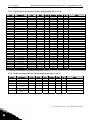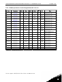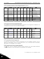
1
user's manual nx frequency converters 3-speed positioning application apfiff15 2 • vacon Introduction INDEX 1. 2. 3. 4. 5. Introduction ..................................................................................................................................... 3 Control I/O ....................................................................................................................................... 4 Control signal logic in Synchronize Positioning Application ......................................................... 5 Positioning sequence ...................................................................................................................... 6 Synchronize Positioning Application – Parameter lists................................................................. 7 5.1 Monitoring values (Control keypad: menu M1) ...................................................................... 7 5.2 Control/Status Words ............................................................................................................. 9 5.3 Basic parameters (Control keypad: Menu M2 Æ G2.1) ....................................................... 11 5.4 Input signals (Control keypad: Menu M2 Æ G2.2)................................................................ 12 5.5 Output signals (Control keypad: Menu M2 Æ G2.3) ............................................................. 14 5.6 Drive control parameters (Control keypad: Menu M2 Æ G2.4) ........................................... 16 5.7 Reserved................................................................................................................................ 16 5.8 Motor control parameters (Control keypad: Menu M2 Æ G2.6) .......................................... 17 5.9 Protections (Control keypad: Menu M2 Æ G2.7).................................................................. 19 5.10 Autorestart parameters (Control keypad: Menu M2 Æ G2.8) ............................................. 20 5.11 Positioning parameters (Control keypad: Menu M2 Æ G2.9) .............................................. 21 5.12 Fixed Positions parameters (Control keypad: Menu M2 Æ G2.10) ..................................... 22 5.13 Brake Control parameters (Control keypad: Menu M2 Æ G2.11) ....................................... 22 5.14 Fieldbus parameters (Control Keypad: Menu M2 ÆG2.12)................................................. 23 5.15 SystemBus parameters (Control keypad: Menu M2 Æ G2.11) ............................................ 24 5.16 Keypad control (Control keypad: Menu M3) ......................................................................... 24 5.17 System menu (Control keypad: M6) ..................................................................................... 24 5.18 Expander boards (Control keypad: Menu M7)...................................................................... 24 6. Description of parameters............................................................................................................ 25 7. Synchronise Positioning parameters ........................................................................................... 26 7.1 Keypad control parameters .................................................................................................. 34 8. Appendices .................................................................................................................................... 35 8.1 External brake control with additional limits (ID’s 315, 316, 346 to 349, 352, 353) ............ 35 8.2 Closed loop parameters (ID’s 612 to 621) ............................................................................ 37 8.3 Parameters of motor thermal protection (ID’s 704 to 708):................................................ 37 8.4 Parameters of Stall protection (ID’s 709 to 712): ................................................................ 38 8.5 Parameters of Underload protection (ID’s 713 to 716):....................................................... 38 8.6 Fieldbus control parameters (ID’s 850 to 859)..................................................................... 38 9. Faults and fault codes................................................................................................................... 39 Tel. +358 (0)201 2121 • Fax +358 (0)201 212 205 Introduction vacon • 3 Synchronize positioning 1. Introduction Frequency converter works as a positioning controller with the help of encoder. Encoder should be installed on motor shaft but also it’s possible to use encoder after gear. When encoder is in motor shaft it’s possible to use closed loop motor control. This makes positioning more accurate. Application support also System Bus communication this communication makes possible to synchronization with two drives. Master drive sends it’s actual position to Follower drive and follower correct it’s speed reference to stay in position window if follower drive fails to stay in window follower sends stop request to master an both drive stops at the same time with minimum position difference. Additional functions: • • • • • • • • • • • • Programmable Start/Stop and Reverse signal logic Reference scaling One frequency limit supervision Second ramps and S-shape ramp programming Programmable start and stop functions DC-brake at stop One prohibit frequency area Programmable U/f curve and switching frequency Auto restart Motor thermal and stall protection: Programmable action; off, warning, fault Automatic encoder recognition (Incremental/Absolute) Auto stop when calibrated 24-hour support +358 (0)40 837 1150 • Email: [email protected] 1 4 • vacon 2. Control I/O Control I/O Reference potentiometer, 1…10 kΩ READY mA NXOPTA1 Terminal 1 +10Vref 2 AI1+ Signal Reference output Analogue input, voltage range 0—10V DC Description Voltage for potentiometer, etc. Voltage input frequency reference 3 4 5 AI1AI2+ AI2- I/O Ground Analogue input, current range 0—20mA Ground for reference and controls Current input frequency reference 6 7 8 +24V GND DIN1 Voltage for switches, etc. max 0.1 A Ground for reference and controls Contact closed = start forward 9 DIN2 10 DIN3 Control voltage output I/O ground Start forward (programmable) Start reverse (programmable) Preset Speed (programmable) 11 CMA Common for DIN 1—DIN 3 12 13 14 +24V GND DIN4 15 DIN5 16 DIN6 17 18 19 20 CMB AO1+ AO1DO1 Control voltage output I/O ground Reset calibration (programmable) Active positioning (programmable) Calibration input (programmable) Common for DIN4—DIN6 Output frequency Analogue output Digital output READY Contact closed = start reverse Contact open = Not Activ Contact closed = Preset speed activ Connect to GND or +24V Voltage for switches (see #6) Ground for reference and controls Raising edge calibration Connect to GND or +24V Programmable Range 0—20 mA/RL, max. 500Ω Programmable Open collector, I≤50mA, U≤48 VDC NXOPTA2 Calibrated 220 VAC 21 22 23 RO1 RO1 RO1 Relay output 1 Calibration OK Programmable 24 25 26 RO2 RO2 RO2 Relay output 2 FAULT Programmable Table 2-1. Synchronize Positioning application default I/O configuration. Note: See jumper selections below. More information in the product’s User's Manual. Jumper block X 3 : CM A a nd CM B grounding CMB connected to GN D CMA connected to GN D CMB isolated from GN D CMA isolated from GN D CMB and CMA internally connected together, isolated from GN D = Factory default Tel. +358 (0)201 2121 • Fax +358 (0)201 212 205 2 Control signal logic in Synchronize Positioning Application 3. vacon • 5 Control signal logic in Synchronize Positioning Application 3.2 Keypad reference 2.1.11 I/O Reference 2.1.12 Keypad Ctrl Reference 2.1.13 Fieldbus Ctrl Reference 2.1.14 Preset Speed 1 2.1.15 Preset Speed 2 DIN4 DIN5 AI1 AI2 3.1 Control place Internal frequency reference Reference from fieldbus Reset button Start/Stop buttons Start/Stop from fieldbus Direction from fieldbus DIN1 DIN2 Start forward (programmable) Start reverse (programmable) Programmable Start/Stop and reverse logic Start/Stop Internal Start/Stop Reverse Internal reverse 3.3 Keypad direction DIN6 DIN3 Fault reset input >1 Internal fault reset External fault input (programmable) NX12k01 Figure 3-1. Control signal logic of the Synchronize Positioning Application 24-hour support +358 (0)40 837 1150 • Email: [email protected] 3 6 • vacon 4. Positioning sequence Positioning sequence Speed [Hz] High Level Speed P2.9.2.4 Mid Level Speed STOP HYSTERES P2.9.2.9 P2.9.2.6 Low Level Speed P2.9.2.8 Speed group 2 HLS 2 P2.9.2.10 MLS 2 P2.9.2.11 LLS 2 P2.9.2.12 Trip [ANY] Mid Speed Distance P2.9.2.5 Low Speed Distance P2.10.8 Figure 4-1. Positioning sequence of the Synchronize Positioning Application Positioning uses three different speed. When approaching the target, speed is decelerated with three different phases. There are also two different speed groups, for example positioning with or without the load. Tel. +358 (0)201 2121 • Fax +358 (0)201 212 205 4 Synchronize Positioning Application – Parameter lists 5. vacon • 7 Synchronize Positioning Application – Parameter lists On the next pages you will find the lists of parameters within the respective parameter groups. The parameter descriptions are given on pages 25 to 34. The descriptions are arranged according to the ID number of the parameter. Column explanations: Code Parameter Min Max Unit Default Cust ID 5.1 = Location indication on the keypad; Shows the operator the present parameter number = Name of parameter = Minimum value of parameter = Maximum value of parameter = Unit of parameter value; Given if available = Value preset by factory = Customer’s own setting = ID number of the parameter = In parameter row: Use TTF method to program these parameters. = On parameter code: Parameter value can only be changed after the frequency converter has been stopped. Monitoring values (Control keypad: menu M1) The monitoring values are the actual values of parameters and signals as well as statuses and measurements. Monitoring values cannot be edited. See the product’s User’s Manual for more information. Code V1.1.1 Parameter Output frequency Frequency reference Unit Hz Hz ID 1 25 V1.1.3 V1.1.4 Motor speed Motor current V1.1.5 Motor torque rpm A % 2 3 4 V1.1.6 V1.1.7 V1.1.8 V1.1.9 V1.1.10 V1.1.11 V1.1.12 V1.1.13 V1.1.14 Motor power Motor voltage DC link voltage Unit temperature Motor temperature Analogue input 1 Analogue input 2 DIN1, DIN2, DIN3 DIN4, DIN5, DIN6 % V V °C 5 6 7 8 9 13 14 15 16 V1.1.15 DO1, RO1, RO2 V1.1.16 Analogue Iout M1.17 Monitoring items V1.1.2 % V mA 17 mA 26 Description Output frequency to motor Frequency reference to motor control Motor speed in rpm In % of the nominal motor torque Motor shaft power Heatsink temperature Calculated motor temperature AI1 AI2 Digital input statuses Digital input statuses Digital and relay output statuses AO1 Displays three selectable monitoring values Table 5-1. Basic monitoring values 24-hour support +358 (0)40 837 1150 • Email: [email protected] 5 8 • vacon Synchronize Positioning Application – Parameter lists Code V1.2.1 V1.2.2 V1.2.3 V1.2.4 V1.2.5 V1.2.6 V1.2.7 V1.2.8 V1.2.9 Parameter Actual Position Target Position Master Position Position error ENC Revolution ENC Fragment ABS Revolution ABS Fragments Scaled ABS Position Unit ID 1551 1553 1623 1625 1580 1581 1629 1630 1632 Description Actual position in user units Target position in user units Received by follower Error of master and follower Rounds of incremental Fragments of incremental Absolute encoder Absolute encoder Scaled value for incremental monitor ID 1700 Description Position Control Word (PCW) from fielbus Position Status Word (PSW) to fielbus Position reference from fielbus Table 5-2. Position monitoring values Code V1.3.1 V1.3.2 V1.3.3 V1.3.4 V1.3.5 V1.3.6 V1.3.7 Parameter FB Position Control Word FB Position Status Word FB Position Reference FB Target Position Unit 1701 1730 1633 1634 FB Actual Position FB Maximum Speed 1721 FB General Status Word 1750 Monitored reference with additional offset Monitored actual position with additional offset Adjust positioning maximum speed from fielbus Additional positioning status word to fielbus. Table 5-3. Fielbus monitoring values Values that can be used as commands from fielbus are market as grey Code V1.4.1 V1.4.2 V1.4.3 V1.4.4 V1.4.5 V1.4.6 Parameter Current Torque DC Voltage Unit A % V Status Word Frequency Ramp Out Encoder 1 Frequency ID 1113 1081 1082 1702 1129 1615 Description Unfiltered current for MonBus Unfiltered toque for MonBus Unfiltered DC-Voltage for MonBus Application Status Word (ASW) Output of ramp generator Table 5-4. MonBus monitoring values Tel. +358 (0)201 2121 • Fax +358 (0)201 212 205 5 Synchronize Positioning Application – Parameter lists 5.2 5.2.1 vacon • 9 Control/Status Words Positioning Control Word (PCW) FALSE Comments TRUE b0 FB Calibration Calibration input from FB b1 FB Positioning mode ON Positioning Command from Fielbus b2 FB Speed Group 2 b3 b4 b5 FB Reset Calibration Command for reseting calibration. b6 Calibration Prohibited Any of calibration input are ignored b7 Set Zero Point ABS Set Zero point for ABS Enc. b8 Set Total Rounds ABS Set Total rounds for ABS Enc. b9 Set Target Offset point Sets offset for reference position ByPass SyncError Fynchronization fault is ignoreg b10 b11 b12 b13 b14 b15 Table 5-5. Positioning Control Word 5.2.2 Positioning Status Word (PSW) FALSE TRUE b0 Calibrated b1 Position Reached b2 Positioning Maximum Speed FB Low area & Position Reached FB High area & Position Reached Master Follower Mode ON b3 b4 b5 Comments b6 b7 b8 Poitionin mode active b9 Calibration Input b10 Synchronizing Error b11 Warning Low End b12 Warning High End b13 Out Of Area b14 Run Enable Low End b15 Make new calibration Run Enable High End Table 5-6. Positioning Status Word 24-hour support +358 (0)40 837 1150 • Email: [email protected] 5 10 • vacon 5.2.3 b0 b1 b2 b3 b4 b5 b6 b7 b8 b9 b10 b11 b12 b13 b14 b15 Synchronize Positioning Application – Parameter lists FBGeneralStatusWord FALSE TRUE Not Reasy Ready Stop Run No Fault Fault No Warning Warning Comments Calibrated Position reached Positioning ON Synchronize error Out of Area Table 5-7. FBGeneralStatusWord Tel. +358 (0)201 2121 • Fax +358 (0)201 212 205 5 Synchronize Positioning Application – Parameter lists 5.3 vacon • 11 Basic parameters (Control keypad: Menu M2 Æ G2.1) Code P2.1.1 Parameter Min frequency Min 0,00 Max Par. 2.1.2 Unit Hz Default 0,00 Cust ID 101 P2.1.2 Max frequency Par. 2.1.1 320,00 Hz 50,00 102 P2.1.3 P2.1.4 P2.1.5 Acceleration time 1 Deceleration time 1 Current limit 0,01 0,01 0,0 300,00 300,00 2 x IH s s A 103 104 107 P2.1.6 Nominal voltage of the motor 180 690 V 3,00 3,00 IL NX2: 230V NX5: 400V NX6: 690V P2.1.7 Nominal frequency of the motor 8,00 320,00 Hz 50,00 111 P2.1.8 Nominal speed of the motor 24 20 000 rpm 1440 112 P2.1.9 Nominal current of the motor 0,2 x IH 2 x IH A IH 113 2.1.10 Motor cosϕ 0,30 1,00 0,85 120 2.1.11 I/O reference 0 3 0 117 2.1.12 Keypad control reference 0 3 2 121 2.1.13 Fieldbus control reference 0 3 3 122 2.1.14 Position Reference Selector 0 3 2 1548 2.1.15 Preset speed 1 0,00 Par. 2.1.2 10,00 105 Hz Note NOTE: If fmax > than the motor synchronous speed, check suitability for motor and drive system 110 Check the rating plate of the motor The default applies for a 4-pole motor and a nominal size frequency converter. Check the rating plate of the motor. Check the rating plate of the motor 0=AI1 1=AI2 2=Keypad 3=Fieldbus 0=AI1 1=AI2 2=Keypad 3=Fieldbus 0=AI1 1=AI2 2=Keypad 3=Fieldbus 0=Din Sel. Position Ref. 1=AI Position Ref. 2=FB Position Ref. 3=Master Position Ref. Speeds preset by operator Table 5-8. Basic parameters G2.1 24-hour support +358 (0)40 837 1150 • Email: [email protected] 5 12 • vacon 5.4 Synchronize Positioning Application – Parameter lists Input signals (Control keypad: Menu M2 Æ G2.2) 5.4.1 Code Basic Settings (Control keypad: Menu M2 Æ G2.2.1) Parameter Min Max Unit Default Cust ID 300 0 1 2 3 4 5 6 P2.2.1.1 Start/Stop logic 0 6 0 P2.2.1.2 Current reference offset 0 1 1 302 P2.2.1.3 Reference scaling minimum value 0,00 par. 2.2.5 Hz 0,00 303 P2.2.1.4 Reference scaling maximum value 0,00 320,00 Hz 0,00 304 P2.2.1.5 Reference inversion 0 1 0 305 P2.2.1.6 Reference filter time 0,00 10,00 0,10 306 P2.2.1.7 Position AI Sel 0.0 E.10 A.2 1549 s Note DIN1 Start fwd Start/Stop Start/Stop Start pulse Fwd* Start*/Stop Start*/Stop DIN2 Start rvs Rvs/Fwd Run enable Stop pulse Rvs* Rvs/Fwd Run enable 0=0—20mA 1=4—20mA Selects the frequency that corresponds to the min. reference signal 0,00 = No scaling Selects the frequency that corresponds to the max. reference signal 0,00 = No scaling 0 = Not inverted 1 = Inverted 0 = No filtering TTF programming method used. Table 5-9. Input signals, G2.2 * = Rising edge required to start Tel. +358 (0)201 2121 • Fax +358 (0)201 212 205 5 Synchronize Positioning Application – Parameter lists vacon • 13 Digital inputs (Control keypad: Menu M2 Æ G2.2.4) 5.4.2 Cust Code Parameter Min Default P2.2.2.1 Run enable 0 0.1 407 P2.2.2.2 Reverse 0 0.1 412 P2.2.2.3 P2.2.3.4 P2.2.2.5 P2.2.2.6 Preset speed 1 Fault reset External fault (close) External fault (open) 0 0 0 0 A.3 A.1 0.1 0.2 419 414 405 406 P2.2.2.7 Acc/Dec time selection 0 A.6 408 P2.2.2.8 Control from I/O terminal 0 0.1 409 P2.2.2.9 Control from keypad 0 0.1 410 P2.2.2.10 Control from fieldbus 0 0.1 411 P2.2.2.11 P2.2.2.12 P2.2.2.13 P2.2.2.14 P2.2.2.15 P2.2.2.16 P2.2.2.17 Positioning mode ON Calibration Select DIN Pos b0 Select DIN Pos b1 Select DIN Pos b2 Select DIN Pos b3 Select DIN Pos b4 0 0 0 0 0 0 0 A.5 A.6 0.1 0.1 0.1 0.1 0.1 1564 1566 1567 1568 1569 1570 1571 P2.2.2.18 External brake enable 0 0.1 1605 P2.2.2.19 P2.2.2.20 P2.2.2.21 P2.2.2.22 Run Enable Low End Run Enable High End Reset Calibration Calibration Negative Calibration Signal Prohibited Positioning Speed Group 2 0 0 0 0 0.1 0.1 A.4 0.1 1609 1608 1611 1612 0 0.1 1613 0 0.1 1563 P2.2.2.23 P2.2.2.24 ID Note Motor start enabled (cc) Direction forward (oc) Direction reverse (cc) All faults reset (cc) Ext. fault displayed (cc) Ext. fault displayed (oc) Acc/Dec time 1 (oc) Acc/Dec time 2 (cc) Force control place to I/O terminal (cc) Force control place to keypad (cc) Force control place to fieldbus (cc) Allows brake open command Table 5-10. Digital input signals, G2.2.4 5.4.3 Maximum Speed Scaling (Menu M2 Æ G2.2.3) Code Parameter Min Max P2.2.3.1 High level speed scaling input 0 3 0.00 P2.2.3.3 P2.2.3.2 P2.2.3.2 P2.2.3.3 P2.2.3.4 P2.2.3.5 cc = closing contact oc = opening contact High level speed 1 minimum High level speed 1 maximum High level speed 2 minimum High level speed 2 maximum Unit Default Cust ID 0 1579 % 0.00 1582 200.00 % 100.00 1584 0.00 P2.2.3.5 % 0.00 1583 P2.2.3.4 200.00 % 100.00 1585 Note 0=Not Used 1=AI1 2=AI2 3=Fielbus Positioning speed group 1 scaling minimum value Positioning speed group 1 scaling maximum value Positioning speed group 2 scaling minimum value Positioning speed group 2 scaling maximum value Table 5-11. Input signals, G2.2 * = Rising edge required to start 24-hour support +358 (0)40 837 1150 • Email: [email protected] 5 14 • vacon 5.5 Synchronize Positioning Application – Parameter lists Output signals (Control keypad: Menu M2 Æ G2.3) Code Parameter Min Max P2.3.1 Analogue output function 0 8 0,00 10,00 0 P2.3.2 P2.3.3 P2.3.4 P2.3.5 P2.3.6 P2.3.7 P2.3.8 Analogue output filter time Analogue output inversion Analogue output minimum Analogue output scale Digital output 1 function Relay output 1 function Relay output 2 function Unit Default Cust ID 1 307 1,00 308 1 0 309 0 1 0 310 10 1000 100 311 s % Note 0=Not used 1=Output freq. (0—fmax) 2=Freq. reference (0—fmax) 3=Motor speed (0—Motor nominal speed) 4=Motor current (0—InMotor) 5=Motor torque (0—TnMotor) 6=Motor power (0—PnMotor) 7=Motor voltage (0--UnMotor) 8=DC-link volt (0—1000V) 9=Ref position 10=Actual position 0=No filtering 0 = Not inverted 1 = Inverted 0 = 0 mA 1 = 4 mA 0 16 1 312 0=Not used 1=Ready 2=Run 3=Fault 4=Fault inverted 5=FC overheat warning 6=Ext. fault or warning 7=Ref. fault or warning 8=Warning 9=Reversed 10=Preset speed 1 11=At speed 12=Mot. regulator active 13=OP freq. limit 1 superv. 14=Control place: IO 15=Thermistor fault/warng 16=Fieldbus input data 17=Calibration OK 18=Position reached 19=High Level Speed 20=Mid Level Speed 21=Low Level Speed 22=Out of Area 23=Forbidden Area 24=Brake Off Control 0 16 2 313 As parameter 2.3.6 0 16 3 314 As parameter 2.3.6 0 315 0=No limit 1=Low limit supervision 2=High limit supervision 0,00 316 P2.3.9 Output frequency limit 1 supervision 0 2 P2.3.10 Output frequency limit 1; Supervised value 0,00 320,00 Hz Tel. +358 (0)201 2121 • Fax +358 (0)201 212 205 5 Synchronize Positioning Application – Parameter lists P2.3.11 P2.3.12 P2.3.13 P2.3.14 P2.3.15 P2.3.16 Analogue output 2 signal selection Analogue output 2 function Analogue output 2 filter time Analogue output 2 inversion Analogue output 2 minimum Analogue output 2 scaling 0 vacon • 15 0.1 471 TTF programming method used. 4 472 As parameter 2.3.1 1,00 473 0=No filtering 0 8 0,00 10,00 0 1 0 474 0 1 0 475 10 1000 100 476 s % 0=Not inverted 1=Inverted 0=0 mA 1=4 mA Table 5-12. Output signals, G2.3 24-hour support +358 (0)40 837 1150 • Email: [email protected] 5 16 • vacon 5.6 Synchronize Positioning Application – Parameter lists Drive control parameters (Control keypad: Menu M2 Æ G2.4) Code Parameter Min Max Unit Default Cust ID P2.4.1 Ramp 1 shape 0,0 10,0 s 0,0 500 P2.4.2 Ramp 2 shape 0,0 10,0 s 0,0 501 P2.4.3 P2.4.4 Acceleration time 2 Deceleration time 2 0,1 0,1 3000,0 3000,0 s s 10,0 10,0 502 503 P2.4.5 Brake chopper 0 4 0 504 P2.4.6 Start function 0 1 0 505 P2.4.7 Stop function 0 3 0 506 P2.4.8 DC braking current DC braking time at stop Frequency to start DC braking during ramp stop DC braking time at start 0,4 x IH 2 x IH A IH 507 0,00 30,000 s 0,000 508 0,10 10,00 Hz 1,50 515 0,00 30,000 s 0,000 516 P2.4.12 Flux brake 0 1 0 520 P2.4.13 Flux braking current Automatic ramp scaling Ramp Scale Frequency 0,4 x IH 2 x IH IH 519 0 1 1 1572 Hz 50,00 1614 Unit Default 0 P2.4.9 P2.4.10 P2.4.11 P2.4.14 P2.4.15 0,00 320,00 A Note 0 = Linear >0 = S-curve ramp time 0 = Linear >0 = S-curve ramp time 0=Disabled 1=Used when running 2=External brake chopper 3=Used when stopped/running 4=Used when running (no testing) 0=Ramp 1=Flying start 0=Coasting 1=Ramp 2=Ramp+Run enable coast 3=Coast+Run enable ramp 0 = DC brake is off at stop 0 = DC brake is off at start 0 = Off 1 = On Table 5-13. Drive control parameters, G2.4 5.7 Reserved Code P2.5.x Parameter Reserved Min 0 Max 0 Cust ID Note Table 5-14. Reserved parameters, G2.5 Tel. +358 (0)201 2121 • Fax +358 (0)201 212 205 5 Synchronize Positioning Application – Parameter lists 5.8 vacon • 17 Motor control parameters (Control keypad: Menu M2 Æ G2.6) Code Parameter Min Max Unit Default Cust ID P2.6.1 Motor control mode 0 1/3 0 600 P2.6.2 U/f optimisation 0 1 0 109 P2.6.3 U/f ratio selection 0 3 0 108 Note NXS: 0=Frequency control 1=Speed control Additionally for NXP: 2=Torque control 3=Closed loop speed ctrl 0=Not used 1=Automatic torque boost 0=Linear 1=Squared 2=Programmable 3=Linear with flux optim. Field weakening point Voltage at field weakening point U/f curve midpoint frequency 8,00 320,00 Hz 50,00 602 10,00 200,00 % 100,00 603 0,00 par. P2.6.4 Hz 50,00 604 P2.6.7 U/f curve midpoint voltage 0,00 100,00 % 100,00 605 n% x Unmot Parameter max. value = par. 2.6.5 P2.6.8 Output voltage at zero frequency 0,00 40,00 % Varies 606 n% x Unmot P2.6.9 Switching frequency 1,0 Varies kHz Varies 601 P2.6.10 Overvoltage controller 0 2 0 607 0 608 0,00 100,0 620 609 0 631 612 613 614 P2.6.4 P2.6.5 P2.6.6 0 1 P2.6.12 P2.6.13 Undervoltage controller Load drooping Torque Limit 0,00 0,0 100,00 300,0 P2.6.14 Identification 0 1/2 P2.6.11 P2.6.15.1 P2.6.15.2 P2.6.15.3 P2.6.15.4 P2.6.15.5 P2.6.15.6 P2.6.15.7 P2.6.15.8 P2.6.15.9 Magnetizing current 0,00 Speed control P gain 0 Speed control I time 0,0 Acceleration 0,00 compensation Slip adjust 0 Magnetizing current MotCurr Min at start Magnetizing time at 0,0 start 0-speed time at start 0 0-speed time at stop 0 % % 100,00 1000 500,0 A ms 0,00 30 30,0 300,00 s 0,00 626 500 MotCurr Max % 100 619 A 0,00 627 30,000 s 0,000 628 32000 32000 ms ms 100 100 615 616 n% x Unmot See Error! Reference source not found. for exact values 0=Not used 1=Used (no ramping) 2=Used (ramping) 0=Not used 1=Used 0=No Action/Ready 1=ID W/O Run 2=ID Run (NXP) 24-hour support +358 (0)40 837 1150 • Email: [email protected] 5 18 • vacon Synchronize Positioning Application – Parameter lists P2.6.15.10 Start-up torque 0 3 P2.6.15.11 P2.6.15.12 P2.6.15.13 Start-up torque FWD Start-up torque REV Encoder filter time Current control P gain Stop State Flux Flux Off Delay –300,0 –300,0 0 300,0 300,0 1000 0,00 0,0 0 P2.6.15.14 P2.6.15.15 P2.6.15.16 0 621 % % ms 0,0 0,0 0 633 634 618 100,00 % 40,00 617 150,0 32000 % s 100,0 0 1401 1402 0=Not used 1=Torque memory 2=Torque reference 3=Start-up torque fwd/rev Table 5-15. Motor control parameters, G2.6 Tel. +358 (0)201 2121 • Fax +358 (0)201 212 205 5 Synchronize Positioning Application – Parameter lists 5.9 vacon • 19 Protections (Control keypad: Menu M2 Æ G2.7) Code Parameter Min Max P2.7.1 Response to 4mA reference fault 0 5 0,00 Par. 2.1.2 0 P2.7.2 P2.7.3 4mA reference fault frequency Response to external fault Unit Default Cust ID 0 700 0,00 728 3 2 701 Hz P2.7.4 Input phase supervision 0 3 0 730 P2.7.5 Response to undervoltage fault 0 1 0 727 0 3 2 702 0 3 2 703 0 3 2 704 –100,0 100,0 % 0,0 705 0,0 150,0 % 40,0 706 1 200 min 45 707 0 100 % 100 708 P2.7.6 P2.7.7 P2.7.8 P2.7.9 P2.7.10 P2.7.11 P2.7.12 Output phase supervision Earth fault protection Thermal protection of the motor Motor ambient temperature factor Motor cooling factor at zero speed Motor thermal time constant Motor duty cycle P2.7.13 Stall protection 0 3 P2.7.14 P2.7.15 P2.7.16 Stall current Stall time limit Stall frequency limit 0,1 1,00 1,0 InMotor x 2 120,00 Par. 2.1.2 P2.7.17 P2.7.18 P2.7.19 P2.7.20 P2.7.21 Underload protection Field weakening area load Zero frequency load Underload protection time limit Response to thermistor fault 0 3 10 150 5,0 2 0 A s Hz 0 709 IL 15,00 25,0 710 711 712 0 713 % 50 714 150,0 % 10,0 715 600 s 20 716 3 2 732 Note 0=No response 1=Warning 2=Warning+Previous Freq. 3=Wrng+PresetFreq 2.7.2 4=Fault,stop acc. to 2.4.7 5=Fault,stop by coasting 0=No response 1=Warning 2=Fault,stop acc. to 2.4.7 3=Fault,stop by coasting 0=Fault stored in history 1=Fault not stored 0=No response 1=Warning 2=Fault,stop acc. to 2.4.7 3=Fault,stop by coasting 0=No response 1=Warning 2=Fault,stop acc. to 2.4.7 3=Fault,stop by coasting 0=No response 1=Warning 2=Fault,stop acc. to 2.4.7 3=Fault,stop by coasting 0=No response 1=Warning 2=Fault,stop acc. to 2.4.7 3=Fault,stop by coasting 24-hour support +358 (0)40 837 1150 • Email: [email protected] 5 20 • vacon Code P2.7.22 P2.7.23 P2.7.24 P2.7.25 P2.7.26 P2.7.27 P2.7.28 P2.7.29 P2.7.30 P2.7.31 P2.7.32 P2.7.33 P2.7.34 P2.7.35 P2.7.36 Synchronize Positioning Application – Parameter lists Parameter Response to fieldbus fault Response to slot fault Encoder fault respoce Gear ratio Synchronization fault mode Synchronization window Synchronization monitor also in frequency control Low rounds fault limit High rounds fault limit SystemBus communication fault delay Out of Area hysteresis Out Of Area Stop Mode Warning area low Warning area high Warning area speed Min Max Unit 0 3 2 733 See P2.7.21 0 3 2 734 See P2.7.21 0 3 1 1616 See P2.7.21 0,00 320,00 1,0 1617 0 3 2 1619 0 32000 500 1618 0 1 0 1672 0 32000 r 0 1646 0 32000 r 4000 1648 0 30,00 s 3,00 1751 0 60000 15 1650 0 2 1 1575 0 0 60000 60000 100 100 1550 1607 0,00 320,00 5,00 1552 Hz Default Cust ID Note 0=No 1=Yes Only for absolute encoder Only for absolute encoder 0=Coasting 1=System defined 2=Ramping Table 5-16. Protections, G2.7 5.10 Autorestart parameters (Control keypad: Menu M2 Æ G2.8) Code P2.8.1 P2.8.2 Parameter Wait time Trial time Min 0,10 0,00 Max 10,00 60,00 P2.8.3 Start function 0 2 0 719 0 10 0 720 0 10 0 721 0 3 0 722 0 10 0 723 0 10 0 726 0 10 0 725 P2.8.4 P2.8.5 P2.8.6 P2.8.7 P2.8.8 P2.8.9 Number of tries after undervoltage trip Number of tries after overvoltage trip Number of tries after overcurrent trip Number of tries after reference trip Number of tries after motor temperature fault trip Number of tries after external fault trip Unit s s Default 0,50 30,00 Cust ID 717 718 Note 0=Ramp 1=Flying start 2=According to par. 2.4.6 Table 5-17. Autorestart parameters, G2.8 Tel. +358 (0)201 2121 • Fax +358 (0)201 212 205 5 Synchronize Positioning Application – Parameter lists vacon • 21 5.11 Positioning parameters (Control keypad: Menu M2 Æ G2.9) Code Parameter Min Max P2.9.1 Panel positioning Control Word (PPCW) 0 10 Unit Default Cust 0 ID 1643 Note 0=No Action 1=Set Zero Position (ABS) 2=Set Total Rounds 3=Set Ref Offset Point 4=Save current position 5=Recall saved position (ModBus) 6=Calibrated (ABS) 7=Reset Calibration 8=Reset Position (INC) 9=Set INC Calibration Position 10=Set INC total rounds Table 5-18. Panel Positioning Control Word parameters, G2.9 5.11.1 Code P2.9.2.1 P2.9.2.2 P2.9.2.3 P2.9.2.4 P2.9.2.5 P2.9.2.6 P2.9.2.7 P2.9.2.8 P2.9.2.9 P2.9.2.10 P2.9.2.11 P2.9.2.12 P2.9.2.13 P2.9.2.14 Positioning Basic Settings (Menu M2 Æ G2.9.2) Parameter Min Total Distance 0 Total rotations 0 Rotations decimals 0 High Level Speed P2.9.2.6 Middle level speed P2.9.2.7 distance Middle level speed P2.9.2.8 Low level speed P2.9.2.9 distance Low level speed 0,00 Stop hysteresis 0 High level speed 2 P2.9.2.11 Middle level speed 2 P2.9.2.12 Low level speed 2 0,00 Teaching enabled 0 Automatic stop when 0 calibrated Max 60000 65535 4 320,00 Unit r Dec. Hz Default 10000 100,0 1 50,00 Cust ID 1500 1501 1502 1509 P2.9.2.1 2700 1506 P2.9.2.4 25,00 1508 P2.9.2.5 700 1505 P2.9.2.6 P2.9.2.7 P2.1.2 P2.9.2.10 P2.9.2.11 1 3,00 25 25,00 12,50 1,50 0 1507 1504 1512 1511 1510 1513 1 1610 Hz Hz Hz 1 Note 0=No 1=Yes Table 5-19. Positioning basic settings parameters, G2.9.2 5.11.2 Code P2.9.3.1 P2.9.3.2 P2.9.3.3 P2.9.3.4 Absolute encoder parameters (Menu M2 Æ G2.9.3) Parameter Zero revolution Zero position Target Offset Automatic calibration delay Min 0 0 0 Max 32000 32000 30000 Unit r Dec Default 0 0 0 0,00 10,00 s 2,00 Cust ID 1627 1628 1637 Note 1752 Table 5-20. Absolute encoder parameters, G2.9.3 5.11.3 Code P2.9.4.1 P2.9.4.1 Incremental encoder parameters (Menu M2 Æ G2.9.4) Parameter Calibration rounds Calibration fragments Min 0 Max 65000 Unit r Default 0 0 65535 Dec 0 Cust ID 1573 Note 1574 Table 5-21. Incremental encoder parameters, G2.9.4 24-hour support +358 (0)40 837 1150 • Email: [email protected] 5 22 • vacon Synchronize Positioning Application – Parameter lists 5.12 Fixed Positions parameters (Control keypad: Menu M2 Æ G2.10) Code P2.10.1 P2.10.2 P2.10.3 P2.10.4 P2.10.5 P2.10.6 P2.10.7 P2.10.8 P2.10.9 P2.10.10 P2.10.11 P2.10.12 P2.10.13 P2.10.14 P2.10.15 P2.10.16 P2.10.17 P2.10.18 P2.10.19 P2.10.20 P2.10.21 P2.10.22 P2.10.23 P2.10.24 P2.10.25 P2.10.26 P2.10.27 P2.10.28 P2.10.29 P2.10.30 P2.10.31 P2.10.32 Parameter Position 0 Position 1 Position 2 Position 3 Position 4 Position 5 Position 6 Position 7 Position 8 Position 9 Position 10 Position 11 Position 12 Position 13 Position 14 Position 15 Position 16 Position 17 Position 18 Position 19 Position 20 Position 21 Position 22 Position 23 Position 24 Position 25 Position 26 Position 27 Position 28 Position 29 Position 30 Position 31 Min P2.7.34 P2.7.34 P2.7.34 P2.7.34 P2.7.34 P2.7.34 P2.7.34 P2.7.34 P2.7.34 P2.7.34 P2.7.34 P2.7.34 P2.7.34 P2.7.34 P2.7.34 P2.7.34 P2.7.34 P2.7.34 P2.7.34 P2.7.34 P2.7.34 P2.7.34 P2.7.34 P2.7.34 P2.7.34 P2.7.34 P2.7.34 P2.7.34 P2.7.34 P2.7.34 P2.7.34 P2.7.34 Max P2.7.35 P2.7.35 P2.7.35 P2.7.35 P2.7.35 P2.7.35 P2.7.35 P2.7.35 P2.7.35 P2.7.35 P2.7.35 P2.7.35 P2.7.35 P2.7.35 P2.7.35 P2.7.35 P2.7.35 P2.7.35 P2.7.35 P2.7.35 P2.7.35 P2.7.35 P2.7.35 P2.7.35 P2.7.35 P2.7.35 P2.7.35 P2.7.35 P2.7.35 P2.7.35 P2.7.35 P2.7.35 Unit Default 100 100 438 776 1114 1452 1790 2128 2466 2803 3141 3479 3817 4155 4493 4831 5169 5507 5845 6183 6521 6859 7197 7534 7872 8210 8548 8886 9224 9562 9900 5000 Cust ID 1545 1514 1515 1516 1517 1518 1519 1520 1521 1522 1523 1524 1525 1526 1527 1528 1529 1530 1531 1532 1533 1534 1535 1536 1537 1538 1539 1540 1541 1542 1543 1544 Note Table 5-22. Fixed positions parameters parameters, G2.10 5.13 Brake Control parameters (Control keypad: Menu M2 Æ G2.11) Code P2.11.1 P2.11.2 P2.11.3 P2.11.4 P2.11.5 P2.11.6 P2.11.7 Parameter Current limit Torque limit Frequency limit open Brake opening delay Frequency limit close Brake closing delay Mechanical opening delays Min 0 0,0 0,00 0,00 Max Varies 100,0 P2.1.7 10,00 Unit A % Hz s Default 0 0 0 0 Cust ID 1587 1588 1589 1590 0,00 P2.1.7 Hz 0 1591 0,00 10,00 s 0 1592 0,00 10,00 s 0 1594 Note Table 5-23. Brake control parameters, G2.11 Tel. +358 (0)201 2121 • Fax +358 (0)201 212 205 5 Synchronize Positioning Application – Parameter lists vacon • 23 5.14 Fieldbus parameters (Control Keypad: Menu M2 ÆG2.12) Code P2.12.1 P2.12.2 P2.12.3 P2.12.4 P2.12.5 P2.12.6 P2.12.7 P2.12.8 P2.12.9 P2.12.10 P2.12.11 P2.12.12 P2.12.13 P2.12.14 P2.12.15 P2.12.16 P2.12.17 P2.12.18 Parameter Fieldbus data out 1 selection Fieldbus data out 2 selection Fieldbus data out 3 selection Fieldbus data out 4 selection Fieldbus data out 5 selection Fieldbus data out 6 selection Fieldbus data out 7 selection Fieldbus data out 8 selection Process data in 1 control ID Process data in 2 control ID Process data in 3 control ID Process data in 4 control ID Process data in 5 control ID Process data in 6 control ID Process data in 7 control ID Process data in 8 control ID FB low area point FB high area point Unit Default Cus t Min Max ID 0 10000 1634 852 0 10000 1553 853 0 10000 1701 854 0 10000 26 855 0 10000 3 856 0 10000 4 857 0 10000 1 858 0 10000 2 859 0 10000 0 1740 0 10000 0 1741 0 10000 0 1742 0 10000 0 1743 0 10000 0 1744 0 10000 0 1745 0 10000 0 1746 0 10000 0 1747 0 0 60000 60000 2550 7450 1760 1761 Note Choose monitoring data with parameter ID Choose monitoring data with parameter ID Choose monitoring data with parameter ID Choose monitoring data with parameter ID Choose monitoring data with parameter ID Choose monitoring data with parameter ID Choose monitoring data with parameter ID Choose monitoring data with parameter ID Choose controlled data with ID number Choose controlled data with ID number Choose controlled data with ID number Choose controlled data with ID number Choose controlled data with ID number Choose controlled data with ID number Choose controlled data with ID number Choose controlled data with ID number PSW b3 PSW b4 Table 5-24. Fieldbus parameters 24-hour support +358 (0)40 837 1150 • Email: [email protected] 5 24 • vacon Synchronize Positioning Application – Parameter lists 5.15 SystemBus parameters (Control keypad: Menu M2 Æ G2.11) Code Parameter Min Max P2.13.1 Master Follower mode selection 0 2 0,00 3,00 0,00 10,00 0 P2.13.2 P2.13.3 P2.13.4 P2.13.5 P2.13.6 P2.13.7 Maximum ramp correction Maximum speed correction Follower position reference selection Master offset Follower offset Parameter selected master follower Unit Default Cust ID 0 1622 s 0,50 1624 Hz 1,00 1631 3 3 1635 0 0 3000 3000 0 0 1640 1641 0 1 0 1644 Note 0=Not used 1=Parameter select 2=Master 3=Follower Max Correction when error = P2.7.27 Max Correction when error = P2.7.27 0=Din Sel. Position Ref. 1=AI Position Ref. 2=FB Position Ref. 3=Master Position Ref 0= Follower 1= Master Table 5-25. SystemBus parameters, G2.13 5.16 Keypad control (Control keypad: Menu M3) The parameters for the selection of control place and direction on the keypad are listed below. See the Keypad control menu in the Vacon NX User's Manual. Code Parameter Min Max P3.1 Control place 1 3 R3.2 Keypad reference Par. 2.1.1 Par. 2.1.2 P3.3 Direction (on keypad) 0 R3.4 Stop button 0 Unit Default Cust ID 2 125 1 0 123 1 1 114 Note 0 = PC Control 1 = I/O terminal 2 = Keypad 3 = Fieldbus Hz 0 = Forward 1 = Reverse 0=Limited function of Stop button 1=Stop button always enabled Table 5-26. Keypad control parameters, M3 5.17 System menu (Control keypad: M6) For parameters and functions related to the general use of the frequency converter, such as application and language selection, customised parameter sets or information about the hardware and software, see the product’s User's Manual. 5.18 Expander boards (Control keypad: Menu M7) The M7 menu shows the expander and option boards attached to the control board and boardrelated information. For more information, see the product’s User's Manual. Tel. +358 (0)201 2121 • Fax +358 (0)201 212 205 5 Description of parameters 6. vacon • 25 Description of parameters Application is based on one of All-In-One applications, see parameter description below ID 1500 from All-In-One application manual. 24-hour support +358 (0)40 837 1150 • Email: [email protected] 6 26 • vacon 7. 1548 Synchronise Positioning parameters Synchronise Positioning parameters Position reference select With this parameter it’s possible to select where position reference is coming 0 = Digital input selection with fixed positions 1 = Analogue position reference 2 = Fieldbus position reference (Default) 3 = Master position reference 1549 Position reference analogue input Select analogue input for position reference using TTF method. 1564 Positioning mode on/off Select digital input to activate positioning mode from I/O. 1566 Calibration Select digital input to give calibration command from I/O 1567 1568 1569 1570 1571 Digital input fixed reference B0 Digital input fixed reference B1 Digital input fixed reference B2 Digital input fixed reference B3 Digital input fixed reference B4 Select fixed position reference with a combination of digital inputs. Tel. +358 (0)201 2121 • Fax +358 (0)201 212 205 7 Synchronise Positioning parameters Code P2.10.1 P2.10.2 P2.10.3 P2.10.4 P2.10.5 P2.10.6 P2.10.7 P2.10.8 P2.10.9 P2.10.10 P2.10.11 P2.10.12 P2.10.13 P2.10.14 P2.10.15 P2.10.16 P2.10.17 P2.10.18 P2.10.19 P2.10.20 P2.10.21 P2.10.22 P2.10.23 P2.10.24 P2.10.25 P2.10.26 P2.10.27 P2.10.28 P2.10.29 P2.10.30 P2.10.31 P2.10.32 Parameter Position 0 Position 1 Position 2 Position 3 Position 4 Position 5 Position 6 Position 7 Position 8 Position 9 Position 10 Position 11 Position 12 Position 13 Position 14 Position 15 Position 16 Position 17 Position 18 Position 19 Position 20 Position 21 Position 22 Position 23 Position 24 Position 25 Position 26 Position 27 Position 28 Position 29 Position 30 Position 31 Min Max Unit Digital input fixed reference Bx P2.7.34 P2.7.35 P2.7.34 P2.7.35 P2.7.34 P2.7.35 P2.7.34 P2.7.35 P2.7.34 P2.7.35 P2.7.34 P2.7.35 P2.7.34 P2.7.35 P2.7.34 P2.7.35 P2.7.34 P2.7.35 P2.7.34 P2.7.35 P2.7.34 P2.7.35 P2.7.34 P2.7.35 P2.7.34 P2.7.35 P2.7.34 P2.7.35 P2.7.34 P2.7.35 P2.7.34 P2.7.35 P2.7.34 P2.7.35 P2.7.34 P2.7.35 P2.7.34 P2.7.35 P2.7.34 P2.7.35 P2.7.34 P2.7.35 P2.7.34 P2.7.35 P2.7.34 P2.7.35 P2.7.34 P2.7.35 P2.7.34 P2.7.35 P2.7.34 P2.7.35 P2.7.34 P2.7.35 P2.7.34 P2.7.35 P2.7.34 P2.7.35 P2.7.34 P2.7.35 P2.7.34 P2.7.35 P2.7.34 P2.7.35 vacon • 27 Default 100 100 438 776 1114 1452 1790 2128 2466 2803 3141 3479 3817 4155 4493 4831 5169 5507 5845 6183 6521 6859 7197 7534 7872 8210 8548 8886 9224 9562 9900 5000 Cust ID 1545 1514 1515 1516 1517 1518 1519 1520 1521 1522 1523 1524 1525 1526 1527 1528 1529 1530 1531 1532 1533 1534 1535 1536 1537 1538 1539 1540 1541 1542 1543 1544 0 0 0 0 0 0 0 0 0 0 0 0 0 0 0 0 0 1 1 1 1 1 1 1 1 1 1 1 1 1 1 1 1 1 0 0 0 0 0 0 0 0 1 1 1 1 1 1 1 1 0 0 0 0 0 0 0 0 1 1 1 1 1 1 1 1 Note 2 0 0 0 0 1 1 1 1 0 0 0 0 1 1 1 1 0 0 0 0 1 1 1 1 0 0 0 0 1 1 1 1 2 0 0 1 1 0 0 1 1 0 0 1 1 0 0 1 1 0 0 1 1 0 0 1 1 0 0 1 1 0 0 1 1 4 0 1 0 1 0 1 0 1 0 1 0 1 0 1 0 1 0 1 0 1 0 1 0 1 0 1 0 1 0 1 0 1 Table 7-1. 1605 External brake enable When input is FALSE brake will not open even if drive conditions are met 1609 1610 Run enable Low end Run enable high end If one of these input goes FALSE drive will stop immediately however it’s possible to start the drive to run opposite direction where limit was opened. 1611 Digital input for calibration reset Input for resetting calibration that it’s possible to make new calibration 1612 Calibration negative Select digital input to give negative calibration command from I/O 1613 Input for prohibiting calibration signal Prohibit calibration input command used when car needs to come from certain direction to calibration point. 24-hour support +358 (0)40 837 1150 • Email: [email protected] 7 28 • vacon 1563 Synchronise Positioning parameters Positioning speed group 2 Activates positioning speed group 2 1579 High level speed scaling input With this input it’s possible to select positioning speed level scaling input 0 = Not used 1 = AI1 2 = A2 3 = Fielbus 1582 1584 1583 1585 High Speed 1 Scaling Min High Speed 1 Scaling Max High Speed 2 Scaling Min High Speed 2 Scaling Max With these parameter it’s possible to give different scaling values to both speed groups. 1572 Automatic ramp scaling When switching from positioning group to other, function tries to scale frequency ramps so, that deceleration is smoother. This function works best, when the frequencies of speed groups are given in a same ratio. 1614 Ramp scale frequency This is the frequency witch drive will ramp in times of P2.1.3 Acceleration time and P2.1.4 Deceleration time. 1616 Encoder fault mode This function will monitor that output frequency and encoder frequency are in same level. 1617 Gear ratio If encoder is after gear, here it’s possible to se gear ration that encoder monitoring will work also in this case. 1619 Synchronising fault mode When follower drive go beyond it’s positioning window here you can select proper response for that. 0 = No response 1 = Warning 2 = Fault, stop mode after fault according to ID506 3 = Fault, stop mode after fault always by coasting 1618 Synchronising window Positioning error when follower drive is out of positioning window. Tel. +358 (0)201 2121 • Fax +358 (0)201 212 205 7 Synchronise Positioning parameters 1672 vacon • 29 Synchronising monitor for speed control When drive is in speed controlled but still in master follower mode it possible to monitor positioning error. Both drives mast have “Calibration OK”. 1646 1648 Low round fault High round fault When drive uses absolute encoder it’s possible to set fault limits when absolute encoder information exceed these limits. 1571 System Bus fault delay Delay until fault is carried out when communication is missing between master and follower drive. 1650 Out of area hysteretic Out of area fault is generated when actual position is more than total trip + this parameter. 1575 Out of area stop mode When out of area fault occurs here you can select the stop mode. 0 = Coasting 1 = System defined 1 = Ramping 1550 1607 Warning area low Warning area high When actual position is near end limit warning is generated and speed is dropped. 1552 Warning area speed When actual position is in warning area speed is dropped to this value. 1643 Panel positioning control word To this parameter have been gathered most common command 0=No Action 1=Set Zero Position (ABS) Sets zero position information from absolute encoder to frequency converter memory. This point is Zero actual position when using absolute encoder. 2=Set Total Rounds When car is driven manually to high end here you can set the total rounds to memory. If you are using incremental encoder remember to reset position in low end. 3=Set Ref Offset Point Possibility to set different zero actual position when using FB control. Internal actual position is FB Actual postion – this offset. 4=Save current position Saves current position to memory for further use 24-hour support +358 (0)40 837 1150 • Email: [email protected] 7 30 • vacon Synchronise Positioning parameters 5=Recall saved position (ModBus) Recalls saved position to reference. 6=Calibrated (ABS) When using absolute encoder you need to give separate information when drive is calibrated after this dive will make automatic calibration during power up. 7=Reset Calibration Resets calibration that it’s possible to make new calibration 8=Reset Position (INC) Sets incremental rotations and fragments to zero that it’s possible to use PCW command to define total rotations ans calibration position 9=Set INC Calibration Position Stores rotations and fragments to memory from zero position to calibration position 10=Set INC total rounds Stores total round to memory when using incremental encoder 1500 Total distance Total distance units. Default 10000 = 100,00 % = Total rotations 1501 Total rotations Number of rotations. From low end to high end. Value is UINT, select proper decimal number with ID 1502 1502 Rotations decimal Number of decimals in Total rotations. If you can use 2 decimal optimal accuracy is 1/100 of rotation when 1 decimal, accuracy is 1/10 or rotation. 1509 1506 1508 1505 1507 1504 1512 1511 1511 High level speed Mid level speed distance Mid level speed Low level speed distance Low level speed Stop hysteric High level speed 2 Mid level speed 2 Low level speed 2 See chapter 4 Position sequence 1513 Teaching Teaching is possible after the calibration. Conveyor is driven to the wanted position and position is set to memory by input “Calibration”. Position is stored to group G2.10, which is selected with the combination of digital inputs. Tel. +358 (0)201 2121 • Fax +358 (0)201 212 205 7 Synchronise Positioning parameters 1610 vacon • 31 Stop drive when pulses are calibrated When drive receives rising edge of calibration input drive can be stopped automatically with this parameter 1627 1628 Zero revolution Zero position Absolute encoder values in Low end 1637 Target offset Adds some unit to reference e.g. mechanical zero point is different than operational zero point. 1573 1574 Calibration round Calibration fragments Incremental position form low end to calibration point. 1587 Current limit Motor current must exceed this value before brake is opened 1588 Torque limit Motor torque must exceed this value before brake is opened 1589 Frequency limit open Output frequency must exceed this value before brake is opened 1590 Brake opening delay Delay for opening brake when limit are met. 1591 Frequency limit close When frequency goes below this value brake is closed 1592 Brake closing delay Delay for closing brake when limits are met. 1594 Mechanical delay Delay for encoder monitor 24-hour support +358 (0)40 837 1150 • Email: [email protected] 7 32 • vacon 852 to 859 Synchronise Positioning parameters Fieldbus data out selections 1 to 8 Using these parameters, you can monitor any monitoring or parameter value from the fieldbus. Enter the ID number of the item you wish to monitor for the value of these parameters. Some typical values: 1 Output frequency 2 Motor speed 3 Motor current 4 Motor torque 5 Motor power 6 Motor voltage 7 DC link voltage 8 Unit temperature 9 Motor temperature 13 AI1 14 AI2 Table 2. 1740 to 1747 15 16 17 25 26 27 28 31 32 37 Digital inputs 1,2,3 statuses Digital inputs 4,5,6 statuses Digital and relay output statuses Frequency reference Analogue output current AI3 AI4 AO1 (expander board) AO2 (expander board) Active fault 1 Fieldbus data IN selections 1 to 8 Using these parameters, you can control any monitoring or parameter value from the fieldbus. Enter the ID number of the item you wish to control for the value of these parameters. 1760 1761 Low area point High area point PSC b3 & b4 1622 Master/Follower selection Select Master Follower mode 0 = No used 1 = Parameter selection 2 = Master 3 = Follower 1624 Maximum ramp correction When position error between master and follower is equal to positioning window size during acceleration and deceleration this is how much ramp is corrected. 1631 Maximum frequency correction When position error between master and follower is equal to positioning window size during level speed this is how much frequency reference is corrected. Tel. +358 (0)201 2121 • Fax +358 (0)201 212 205 7 Synchronise Positioning parameters 1635 vacon • 33 Follower position reference When drive is follower this selection is used for position reference 0 = Digital input selection with fixed positions 1 = Analogue position reference 2 = Fieldbus position reference 3 = Master position reference (Default) 1640 Master offset Additional offset to follower for monitoring position error. 1641 Follower offset Additional offset to follower for monitoring position error. 1644 Parameter selected master follower mode 0 = Follower 1 = Master 24-hour support +358 (0)40 837 1150 • Email: [email protected] 7 34 • vacon 7.1 Synchronise Positioning parameters Keypad control parameters Unlike the parameters listed above, these parameters are located in the M3 menu of the control keypad. The reference parameters do not have an ID number. 114 Stop button activated (3.4, 3.6) If you wish to make the Stop button a "hotspot" which always stops the drive regardless of the selected control place, give this parameter the value 1. See also parameter ID125. 125 Control Place (3.1) The active control place can be changed with this parameter. For more information, see the product’s User's Manual. Pushing the Start button for 3 seconds selects the control keypad as the active control place and copies the Run status information (Run/Stop, direction and reference). 123 Keypad Direction 0 1 (3.3) Forward: The rotation of the motor is forward, when the keypad is the active control place. Reverse: The rotation of the motor is reversed, when the keypad is the active control place. For more information, see the product’s User's Manual R3.2 Keypad Reference (3.2) The frequency reference can be adjusted from the keypad with this parameter. The output frequency can be copied as the keypad reference by pushing the Stop button for 3 seconds when you are on any of the pages of menu M3. For more information, see the product’s User's Manual. Tel. +358 (0)201 2121 • Fax +358 (0)201 212 205 7 vacon 8. Synchronize Positioning Page 35 Appendices In this chapter you will find additional information on special parameter groups. Such groups are: Parameters of External brake control with additional limits (Chapter 8.1) Closed Loop parameters (Chapter 8.2) Parameters of Motor thermal protection (Chapter 8.3) Parameters of Stall protection (Chapter 8.4) Parameters of Underload protection (Chapter 8.5) Fieldbus control parameters (Chapter 8.6) 8.1 External brake control with additional limits (ID’s 315, 316, 346 to 349, 352, 353) The external brake used for additional braking can be controlled through parameters ID315, ID316, ID346 to ID349 and ID352/ID353. Selecting On/Off Control for the brake, defining the frequency or torque limit(s) the brake should react to and defining the Brake-On/-Off delays will allow an effective brake control. See Figure 8-1. Torque limit ID349 Frequency limit ID347 START STOP Brake off Brake on Brake-off delay; ID352 Brake-on delay; ID353 NX12k115.fh8 Figure 8-1. Brake control with additional limits In Figure 8-1 above, the brake control is set to react to both the torque supervision limit (par. ID349) and frequency supervision limit (ID347). Additionally, the same frequency limit is used for both brake-off and brake-on control by giving parameter ID346 the value 4. Use of two different frequency limits is also possible. Then parameters ID315 and ID346 must be given the value 3. Brake-off: In order for the brake to release, three conditions must be fulfilled: 1) the drive must be in Run state, 2) the torque must be over the set limit (if used) and 3) the output frequency must be over the set limit (if used). 24-hour support +358 (0)40 837 1150 • Email: [email protected] 8 Page 36 Synchronize Positioning vacon Brake-on: Stop command activates the brake delay count and the brake is closed when the output frequency falls below the set limit (ID315 or ID346). As a precaution, the brake closes when the brake-on delay expires, at the latest. Note: A fault or Stop state will close the brake immediately without a delay. See Figure 8-2. It is strongly advisable that the brake-on delay be set longer than the ramp time in order to avoid damaging of the brake. No brake-off control ID346 0-2 Brake-off ctrl, 2 limits Brake-on/off crtl, 1 limit 3 4 TRUE Output frequency ≥ ID347 ID348 0-2 3-4 No brake-off control 0-2 Brake-off ctrl, torque limit 3 TRUE Motor torque ≥ ID349 AND OFFDELAY COUNT 0-2 3 Brake off Brake on Run state NOT ONDELAY COUNT No Run request Reversing No run request OR No brake-on control 0-2 Brake-on ctrl, 2 limits 3 No brake-on control 0-3 ID315 AND 3 OR OR ID346 4 4 Brake-on/off crtl, 1 limit ID316 0-3 ID347 4 Output frequency Fault ≤ NX12k114.fh8 Figure 8-2. Brake control logic Tel. +358 (0)201 2121 • Fax +358 (0)201 212 205 8 vacon 8.2 Synchronize Positioning Page 37 Closed loop parameters (ID’s 612 to 621) Select the Closed loop control mode by setting value 3 or 4 for parameter ID600. Closed loop control is used when enhanced performance near zero speed and better static speed accuracy with higher speeds are needed. Closed loop control mode is based on "rotor flux oriented current vector control". With this controlling principle, the phase currents are divided into a torque producing current portion and a magnetizing current portion. Thus, the squirrel cage induction machine can be controlled in a fashion of a separately excited DC motor. Note: These parameters can be used with Vacon NXP drive only. EXAMPLE: Motor Control Mode = 3 (Closed loop speed control) This is the usual operation mode when fast response times, high accuracy or controlled run at zero frequencies are needed. Encoder board should be connected to slot C of the control unit. Set the encoder P/R-parameter (P7.3.1.1). Run in open loop and check the encoder speed and direction (V7.3.2.2). Change the direction parameter (P7.3.1.2) or switch the phases of motor cables if necessary. Do not run if encoder speed is wrong. Program the no-load current to parameter ID612 and set parameter ID619 (Slip Adjust) to get the voltage slightly above the linear U/f-curve with the motor frequency at about 66% of the nominal motor frequency. The Motor Nominal Speed parameter (ID112) is critical. The Current Limit parameter (ID107) controls the available torque linearly in relative to motor nominal current. 8.3 Parameters of motor thermal protection (ID’s 704 to 708): General The motor thermal protection is to protect the motor from overheating. The Vacon drive is capable of supplying higher than nominal current to the motor. If the load requires this high current there is a risk that the motor will be thermally overloaded. This is the case especially at low frequencies. At low frequencies the cooling effect of the motor is reduced as well as its capacity. If the motor is equipped with an external fan the load reduction at low speeds is small. The motor thermal protection is based on a calculated model and it uses the output current of the drive to determine the load on the motor. The motor thermal protection can be adjusted with parameters. The thermal current IT specifies the load current above which the motor is overloaded. This current limit is a function of the output frequency. The thermal stage of the motor can be monitored on the control keypad display. See the product’s User's Manual. ! CAUTION! The calculated model does not protect the motor if the airflow to the motor is reduced by blocked air intake grill. 24-hour support +358 (0)40 837 1150 • Email: [email protected] 8 Page 38 8.4 Synchronize Positioning vacon Parameters of Stall protection (ID’s 709 to 712): General The motor stall protection protects the motor from short time overload situations such as one caused by a stalled shaft. The reaction time of the stall protection can be set shorter than that of motor thermal protection. The stall state is defined with two parameters, ID710 (Stall current) and ID712 (Stall frequency limit). If the current is higher than the set limit and output frequency is lower than the set limit, the stall state is true. There is actually no real indication of the shaft rotation. Stall protection is a type of overcurrent protection. 8.5 Parameters of Underload protection (ID’s 713 to 716): General The purpose of the motor underload protection is to ensure that there is load on the motor when the drive is running. If the motor loses its load there might be a problem in the process, e.g. a broken belt or a dry pump. Motor underload protection can be adjusted by setting the underload curve with parameters ID714 (Field weakening area load) and ID715 (Zero frequency load), see below. The underload curve is a squared curve set between the zero frequency and the field weakening point. The protection is not active below 5Hz (the underload time counter is stopped). The torque values for setting the underload curve are set in percentage which refers to the nominal torque of the motor. The motor's name plate data, parameter motor nominal current and the drive's nominal current IH are used to find the scaling ratio for the internal torque value. If other than nominal motor is used with the drive, the accuracy of the torque calculation decreases. 8.6 Fieldbus control parameters (ID’s 850 to 859) The Fieldbus control parameters are used when the frequency or the speed reference comes from the fieldbus (Modbus, Profibus, DeviceNet etc.). With the Fieldbus Data Out Selection 1…8 you can monitor values from the fieldbus. Tel. +358 (0)201 2121 • Fax +358 (0)201 212 205 8 vacon 9. Synchronize Positioning Page 39 Faults and fault codes When a fault is detected by the frequency converter control electronics, the drive is stopped and the symbol F together with the ordinal number of the fault, the fault code and a short fault description appear on the display. The fault can be reset with the Reset button on the control keypad or via the I/O terminal. The faults are stored in the Fault History menu, which can be browsed. The different fault codes you will find in the table below. Shadowed rows are the A- faults (alarms) and black rows are F- faults (fault). Texts on the white base could be both A- and F- faults. The fault codes and their possible causes are presented in the table below. Fault code 1 Fault Possible cause Overcurrent 2 Overvoltage Frequency converter has detected too high a current (>4*In) in the motor cable: - sudden heavy load increase - short circuit in motor cables -- unsuitable motor The DC-link voltage has exceeded the limits. - too short a deceleration time - high overvoltage spikes in utility Current measurement has detected that the sum of motor phase current is not zero. insulation failure in cables or motor The charging switch is open, when the START command has been given. - faulty operation - component failure Stop signal has been given from the option board. Defective component Action Check loading. Check motor. Check cables. Make the deceleration time longer. Use brake chopper or brake resistor (available as options) 3 Earth fault 5 Charging switch 6 7 Emergency stop Saturation trip 8 Unknown fault The frequency converter troubleshooting system is unable to locate the fault. 9 Undervoltage DC-link voltage is under the voltage limits defined in Table 4-2 of the Vacon NX User's Manual. Most probable causes: - too low a supply voltage - frequency converter internal fault Reset the fault and restart. Should the fault re-occur, contact the distributor near to you. In case of temporary supply voltage break reset the fault and restart the frequency converter. Check the supply voltage. If it is adequate, an internal failure has occurred. Contact the distributor near to you. 10 Input line supervision Output phase supervision Input line phase is missing. Check supply voltage and cable. Current measurement has detected that there is no current in one motor phase. Check motor cable and motor. 11 Check motor cables and motor. Reset the fault and restart. Should the fault re-occur, contact the distributor near to you. Cannot be reset from the keypad. Switch off power. If this does not help contact the distributor near to you. 24-hour support +358 (0)40 837 1150 • Email: [email protected] 9 Page 40 Synchronize Positioning 12 Brake chopper supervision - 13 Frequency converter undertemperature Frequency converter overtemperatur e Heatsink temperature is under –10°C Motor stalled Motor overtemperatur e Motor underload EEPROM checksum fault Motor stall protection has tripped. Motor overheating has been detected by frequency converter motor temperature model. Motor is overloaded. Motor underload protection has tripped. 14 15 16 17 22 23 no brake resistor installed brake resistor is broken brake chopper failure vacon Check brake resistor. If the resistor is ok, the chopper is faulty. Contact the distributor near to you. Heatsink temperature is over 90°C. Overtemperature warning is issued when the heatsink temperature exceeds 85°C. - parameter save fault - faulty operation - component failure Changes may have occurred in the different counter data due to mains interruption - faulty operation - component failure Check the correct amount and flow of cooling air. Check the heatsink for dust. Check the ambient temperature. Make sure that the switching frequency is not too high in relation to ambient temperature and motor load. Check motor. Decrease the motor load. If no motor overload exists, check the temperature model parameters. 24 Changed data warning 25 Microprocessor watchdog fault 29 Thermistor fault Thermistor is broken. Reset the fault and restart. Should the fault re-occur, contact the distributor near to you. 32 Fan cooling Contact the distributor near to you. 34 36 CAN bus communication Control unit Cooling fan of the frequency converter does not start, when ON command is given Sent message not acknowledged. 37 Device change 38 Device added 39 Device removed 40 Device unknown NXS Control Unit can not control NXP Power Unit and vice versa Option board changed. Different power rating of drive. Option board added. Drive of different power rating added. Option board removed. Drive removed. Unknown option board or drive. Reset the fault and restart. Should the fault re-occur, contact the distributor near to you. Ensure that there is another device on the bus with the same configuration. Change the control unit. Reset Note: No fault time data record! Reset Note: No fault time data record! Reset Note: No fault time data record! Contact the distributor near to you. Tel. +358 (0)201 2121 • Fax +358 (0)201 212 205 9 vacon Synchronize Positioning 41 IGBT temperature 42 Brake resistor overtemperature 43 Encoder fault 50 Analogue input Iin < 4mA (selected signal range 4 to 20 mA) 51 52 External fault Keypad communication fault Fieldbus communication fault Digital input fault. The connection between the control keypad and the frequency converter is broken. The connection from the fieldbus to the frequency converter is broken. 54 SPI communication fault The connection between the component board and the control board is broken. Check board and slot. Contact the nearest Vacon distributor. 55 New calibration Positioning area override Make new calibration 53 IGBT Inverter Bridge overtemperature protection has detected too high a short term overload current Too powerful braking. Page 41 Note the exceptional Fault data record. Additional codes: 1 = Encoder 1 channel A is missing 2 = Encoder 1 channel B is missing 3 = Both encoder 1 channels are missing 4 = Encoder reversed Current at the analogue input is < 4mA. - control cable is broken or loose - signal source has failed Check loading. Check motor size. Set the deceleration time longer. Use external brake resistor. Check encoder channel connections. Check the encoder board. Check the current loop circuitry. Check keypad connection and possible keypad cable. Check installation. If installation is correct contact the nearest Vacon distributor. Table 7- 1. Fault codes 24-hour support +358 (0)40 837 1150 • Email: [email protected] 9 Vaasa Vacon Plc (Head office and production) Runsorintie 7 65380 Vaasa [email protected] telephone: +358 (0)201 2121 fax: +358 (0)201 212 205 Vacon Traction Oy Vehnämyllynkatu 18 33700 Tampere telephone: +358 (0)201 2121 fax: +358 (0)201 212 710 Helsinki Vacon Plc Äyritie 12 01510 Vantaa telephone: +358 (0)201 212 600 fax: +358 (0)201 212 699 Tampere Vacon Plc Vehnämyllynkatu 18 33700 Tampere telephone: +358 (0)201 2121 fax: +358 (0)201 212 750 sales companies and representative offices: Austria Vacon AT Antriebssysteme GmbH Aumühlweg 21 2544 Leobersdorf telephone: +43 2256 651 66 fax: +43 2256 651 66 66 Italy Vacon S.p.A. Via F.lli Guerra, 35 42100 Reggio Emilia telephone: +39 0522 276811 fax: +39 0522 276890 Belgium Vacon Benelux NV/SA Interleuvenlaan 62 3001 Heverlee (Leuven) telephone: +32 (0)16 394 825 fax: +32 (0)16 394 827 The Netherlands Vacon Benelux BV Weide 40 4206 CJ Gorinchem telephone: +31 (0)183 642 970 fax: +31 (0)183 642 971 France Vacon France s.a.s. 1 Rue Jacquard – BP72 91280 Saint Pierre du Perray CDIS telephone: +33 (0)1 69 89 60 30 fax: +33 (0)1 69 89 60 40 Norway Vacon AS Langgata 2 3080 Holmestrand telephone: +47 330 96120 fax: +47 330 96130 Germany Vacon GmbH Gladbecker Strasse 425 45329 Essen telephone: +49 (0)201 806 700 fax: +49 (0)201 806 7099 PR China Vacon Suzhou Drives Co. Ltd. Blk 11A 428 Xinglong Street Suchun Industrial Square Suzhou 215126 telephone: +86 512 6283 6630 fax: +86 512 6283 6618 Great Britain Vacon Drives (UK) Ltd. 18, Maizefield Hinckley Fields Industrial Estate Hinckley LE10 1YF Leicestershire telephone: +44 (0)1455 611 515 fax: +44 (0)1455 611 517 Russia ZAO Vacon Drives Bolshaja Jakimanka 31, stroenie 18 109180 Moscow telephone: +7 (095) 974 14 47 fax: +7 (095) 974 15 54 ZAO Vacon Drives 2ya Sovetskaya 7, office 210A 191036 St. Petersburg telephone: +7 (812) 332 1114 fax: +7 (812) 279 9053 Singapore Vacon Plc Singapore Representative Office 102F Pasir Panjang Road #02-06 Citilink Warehouse Complex Singapore 118530 telephone: +65 6278 8533 fax: +65 6278 1066 Spain Vacon Drives Ibérica S.A. Miquel Servet, 2. P.I. Bufalvent 08243 Manresa telephone: +34 93 877 45 06 fax: +34 93 877 00 09 Vacon Suzhou Drives Co. Ltd. Beijing Office A205, Grand Pacific Garden Mansion 8A Guanhua Road Beijing 100026 telephone: +86 10 6581 3734 fax: +86 10 6581 3754 Sweden Vacon AB Torget 1 172 67 Sundbyberg telephone: +46 (0)8 293 055 fax: +46 (0)8 290 755 Tel. +358 (0)201 2121 • Fax +358 (0)201 212 205 Vacon distributor: