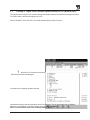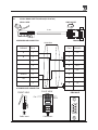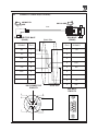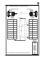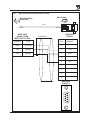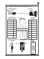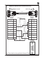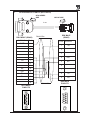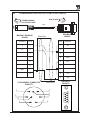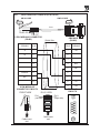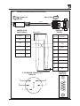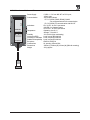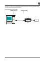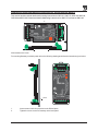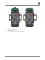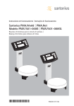
1
GATEWAY
USER’S
MANUAL
Preliminary
Thank you for purchasing Gateway product. Gateway is a versatile Protocol converter / Data sharer with
Windows based configuration Software.
This manual will help you to safely install, configure and operate Gateway Products.
All the safety warnings and precautions must be followed to ensure proper unit performance and personal
safety.
Warnings used in this manual:
DANGER
Danger Warnings are used to indicate situations, locations and
conditions that can cause serious injury or death.
CAUTION
!
Caution Warnings are used to indicate situations and conditions that
can cause operator injury and/or unit damage
IMPORTANT
Gateway Products are intended to be protocol converters / Data sharer devices
that can also take control actions on request of device being connected. It is
assumed that the user is well acquainted with the PLCs / Inverters / Controllers
being used.
Any mechanical or electrical modification to the unit will void all warranties.
ii
Manual Revisions
If you contact us in reference to this manual, please include the following name and revision number
Name: Gateway User’s Manual
Revision: UMAN\GWY\1104\Rev8
Part Code: URML200
Rev. changed from 2 to 3: Note added on page no. 9.
Rev. changed from 3 to 4: Communication cables & REPL Prizm addresses are added.
Rev. changed from 4 to 5: Sartorius to GWY-00 cable added.
Rev. changed from 5 to 6: Baumuller Drive to GWY-00 cable added.
Rev. changed from 6 to 7: Baumuller Drive (2 WIRE) to GWY-00 cable added.
Rev. changed from 7 to 8: Thomson Technology Controller to GWY-00 cable added.
Rev. changed from 8 to 9: System requirement for gateway setup software revised.
We hope that you find this manual informative. If additional information or technical assistance is needed
please contact:
Renu Electronics Private Limited
Survey No. 2/6,
Baner Road, Pune – 411 045
Maharashtra, INDIA
Tel: +91 20 729 2840
Fax: +91 20 729 2839
E-mail: [email protected]
Website: www.renuelectronics.com
iii
Contents
Preliminary .................................................................................................................................. ii
Manual Revisions ...................................................................................................................... iii
INTRODUCTION ...................................................................................................................... 6
1.1
1.2
1.3
1.4
Purpose of this Manual ......................................................................................................... 7
Introduction to Gateway ........................................................................................................ 7
Gateway Applications: ........................................................................................................... 8
Gateway Specifications .......................................................................................................... 9
HARDWARE ............................................................................................................................ 10
2.1
2.2
2.3
Dimensional Details and Mounting Instructions ............................................................ 11
Power Requirements .......................................................................................................... 13
Communication Ports ......................................................................................................... 14
GETTING STARTED .............................................................................................................. 15
3.1
3.2
Introduction to Gateway ...................................................................................................... 16
Gateway Operation - Configuration and Communication .............................................. 16
UNDERSTANDING GATEWAY FEATURES ........................................................................ 18
4.1
Gateway Modes .................................................................................................................... 19
4.1.1
4.1.2
4.2
4.3
4.4
4.5
4.6
4.6
Master-Master configuration
Master-Slave configuration
19
20
Multi-dropping of Devices using Gateway ....................................................................... 22
Repeat Cycle ........................................................................................................................ 23
Control Word ........................................................................................................................ 23
Error Indication Bit ............................................................................................................. 24
Communication Parameters .............................................................................................. 24
Status LEDs .......................................................................................................................... 24
TYPICAL PROJECTS ............................................................................................................. 25
5.1
5.2
5.3
5.4
Project Setup ........................................................................................................................ 26
Example 1: PLC to PLC Communication ....................................................................... 26
Example 2: Higher Level Controller (Modbus master) to PLC (Modbus slave) .... 28
Example 3: PLC (Modbus master) to Other Device (Modbus slave). ...................... 29
CONFIGURATION SOFTWARE ........................................................................................... 30
6.1
6.2
System Requirements: ........................................................................................................ 31
Installation Instructions: ..................................................................................................... 31
CABLE DIAGRAMS ............................................................................................................... 32
7.1
Wiring Diagrams .................................................................................................................. 33
COMMUNICATION CABLES FOR GWY-00 ...................................................................... 34
8.1
8.2
8.3
8.4
8.5
8.6
8.7
8.8
8.9
8.10
8.11
8.12
8.13
8.14
AB SLC DH485 PORT TO GWY-00 (EC-P-007-00) ..................................................... 35
AB MICROLOGIX SERIES PLCs TO GWY-00 (EC-P-027A-00) ............................. 36
A B SLC DF1 PORT TO GWY-00 (EC-P-027B-00) ...................................................... 37
AROMAT FP0/FPM TO GWY-00 (EC-P-015A-00) ...................................................... 38
AROMAT FP1 TO GWY-00 (EC-P-015B-00) ................................................................ 39
AROMAT FP2 TO GWY-00 (EC-P-015D-00) ................................................................ 40
CALISTO PLC TO GWY-00 (EC-P-090-00) .................................................................. 41
GE 90 SERIES PLC TO GWY-00 (EC-P-002-00) .......................................................... 42
GE VERSAMAX PLC TO GWY-00 (EC-P-002B-00) .................................................... 43
GE VERSAMAX PLC TO GWY-00 (EC-P-002A-00) .................................................... 44
IDEC MICRO3 TO GWY-00 (EC-P-025A-00) ............................................................... 45
KEYENCE KV PLC TO GWY-00 (EC-P-018-00) .......................................................... 46
LG MASTER K SERIES PLC TO GWY-00 (EC-P-037-00) ......................................... 47
MITSUBISHI FX SERIES PLC TO GWY-00 (EC-P-008B-00) ................................... 48
8.15
8.16
8.17
8.18
8.19
8.20
8.21
8.22
8.23
8.24
8.25
8.26
8.27
8.28
8.29
8.30
8.31
8.32
8.33
8.34
MITSUBISHI FX0 PLC TO GWY-00 (EC-P-008A-00) ................................................ 49
MODICON MICRO-CONTROLLER TO GWY-00 (EC-P-009B-00) ...................... 50
MOISTURE ANALYSER TO GWY-00 (EC-P-098-00) ................................................. 51
OMRON CQM1 PLC TO GWY-00 (EC-P-006B-00) .................................................... 52
OMRON CQM/CPM CMOS PORT TO GWY-00 (EC-P-006A-00) ........................... 53
RHEONIC MASS FLOW METER TO GWY-00 (EC-P-091A-00) ............................. 54
RHEONIC MASS FLOW METER TO GWY-00 (EC-P-091B-00) ............................. 55
SIEMENS S7-300 SERIES PLC TO GWY-00 (EC-P-077-00) ...................................... 56
SIEMENS STEP 7 MICRO (S7-200) PLC TO GWY-00 (EC-P-029-00) .................... 57
TELEMECHANIQUE TSX-07/TSX-37 PLC TO GWY-00 (EC-P-026A-00) ............ 58
TOSHIBA T1 LINK PORT TO GWY-00 (EC-P-046A-00) .......................................... 59
TOSHIBA T1 PLC TO GWY-00 (EC-P-019A-00) ......................................................... 60
TOSHIBA T2 LINK PORT TO GWY-00 (EC-P-046B-00) .......................................... 61
TOSHIBA T2 PLC TO GWY-00 (EC-P-019B-00) ......................................................... 62
TOSHIBA VF-S7 TO GWY-00 (EC-P-050-00) ............................................................... 63
METTLER TOLEDO TO GWY-00 (EC-P-103-00) ....................................................... 64
SARTORIUS TO GWY-00 (EC-P-104-00) ....................................................................... 65
BAUMULLER DRIVE (RS485 4-WIRE) TO GWY-00 (EC-P-042A-00) .................. 66
BAUMULLER DRIVE (RS485 2-WIRE) TO GWY-00 (EC-P-042B-00) .................. 67
THOMSON TECHNOLOGY CONTROLLER TO GWY-00 (EC-P-117-00) ............ 68
COMMUNICATION CABLES FOR GWY-S7 ...................................................................... 69
9.1
9.2
9.3
9.4
9.5
9.6
9.7
9.8
9.9
9.10
9.11
9.12
9.13
AB MICROLOGIX SERIES PLCs TO GWY-S7 (EC-G7-027A-00) .......................... 70
A B SLC DF1 PORT TO GWY-S7 (EC-G7-027B-00) .................................................... 71
MODICON MICRO-CONTROLLER TO GWY-S7 (EC-G7-009B-00) ................... 72
OMRON CQM1 PLC TO GWY-S7 (EC-G7-006B-00) ................................................. 73
OMRON CQM/CPM CMOS PORT TO GWY-S7 (EC-G7-006A-00) ........................ 74
SIEMENS STEP 7 MICRO (S7-200) PLC TO GWY-S7 (EC-G7-077-00) ................. 75
GE 90 SERIES PLC TO GWY-S7 (EC-G7-002-00) ........................................................ 76
SIEMENS S7-300 PLC TO GWY-S7 (EC-G7-077-00) .................................................. 77
TELEMECHANIQUE TSX-07/TSX-37 PLC TO GWY-S7 (EC-G7-026A-00) .......... 78
AB SLC DH485 PORT TO GWY-S7 (EC-G7-007-00) .................................................. 79
AROMAT FP0/FPM TO GWY-S7 (EC-S7-015A-00) .................................................... 80
AROMAT FP1 TO GWY-S7 (EC-G7-015B-00) .............................................................. 81
AROMAT FP2 TO GWY-S7 (EC-G7-015D-00) .............................................................. 82
COMMUNICATION CABLES FOR GWY-S8 ...................................................................... 83
10.1
SIEMENS S7-300 SERIES PLC TO GWY-S8 (EC-G8-077-00)
84
IBM CABLES .......................................................................................................................... 85
11.1 IBM CABLE FOR GWY-00 & GWY-S8 (IBM 0909-1-00) .......................................... 86
11.2 IBM CABLE FOR GWY-S7 .............................................................................................. 87
TROUBLESHOOTING GUIDE ............................................................................................. 88
ADDENDUM FOR SPECIAL GATEWAY MODELS ........................................................... 91
Special Gateway Models ............................................................................................................... 92
Communication Ports of Special Gateway Models ................................................................... 96
Configuration of Special Gateway Models: ................................................................................ 99
Dimensional Details and Mounting Instructions for Special Gateway Models: ................ 101
Supported PLC’s List for Special Gateway Models ............................................................... 103
INDEX ................................................................................................................................... CIV
INTRODUCTION
In this chapter. . . .
Purpose of this Manual
Introduction to Gateway
Gateway Applications
Gateway Specifications
6
1.1
Purpose of this Manual
The intention of this Operation Manual is to provide a guide for Safe installation, Configuration and operation
of Gateway. This manual is applicable for General purpose Gateway (Part# GWY-00) units. If your Gateway
Part# is other than GYW-00, please refer to ‘Addendum for Special Gateways’ section for hardware specific
details. Functionality of all the Gateway models is same.
Read this operation manual thoroughly before installing and operating Gateway.
This document is based on information available at the time of its publication. While efforts have been made
to be accurate, the information in this document may not cover all the details or variations in hardware or
software. Features described herein may not be present in all hardwares. Renu Electronics reserves the right
to update information in this publication without prior notice.
1.2
Introduction to Gateway
Gateway Series protocol converters provide interface between different devices having different communication protocols. It also provides interface between same communication protocols (Example: Data sharer
between two slaves having the same protocol). Gateway communicates with PLCs / Inverters / Controllers
using RS232 / RS422 / RS485 (2 / 4 wire) or CMOS serial communication.
Configuration of Gateway:
GWY-00
Each Gateway has to be configured using Windows based configuration Software before connecting it to the
PLC.
X Protocol
PLC1
GWY-00
Normal Operation:
Y Protocol
PLC2
Connect each PLC to Gateway via the PLC’s communications port (correct cables are required) and the
PLCs can easily exchange information.
7
1.3
Gateway Applications:
Gateway connects one field device to another over a serial link irrespective of their protocols. User can define
the blocks of registers to be fetched from one device and to be transferred to the other. Gateway units have
been used in various different applications across many industries. The typical configurations include the
followings:
1. PLC to PLC Communication
GWY-00
X Protocol
PLC1
Y Protocol
PLC2
Protocol Converter
Example: GWY-00
by Renu Electronics
GWY-00
2. PLC as a Master in Modbus Network
X Protocol
PLC
Node 1
Motor
Drive
.
.
Protocol Converter
Example: GWY-00
by Renu Electronics
Node n
PID Controller
GWY-00
3. PLC / inverter / Controller as Slaves in Modbus Network
50
RPM
(x10)
0
Modbus
Protocol
Node 1
Drive
Motor
100
GWY-00
RS 232-485
Converter
Converter
Example: CNV-01-02-2-00
by Renu Electronics
Y Protocol
PLC
.
.
.
GWY-00
A
S
T
R
A
X Protocol
SCADA Software
Example: ASTRA
by Renu Electronics
Z Protocol
Node n
PID Controller
8
Node 2
1.4
Gateway Specifications
Power Supply
Communication
: 24 VDC +/- 10 %, 100 mA max
: Two ports as follows:
PLC1 : RS232C / RS422 / RS485 / CMOS
For configuration and PLC communication
PLC2: RS232C / RS422 / RS485 / CMOS
For PLC communication
Indications
: PLC1 LED - for PLC1 port status
OK LED - for Gateway status
PLC2 LED - for PLC2 port status
Temperature
: Operating: 0 to 60 °C
Storage: - 40 to 90 °C
Humidity
: 10% to 90% (Non condensing)
Immunity to ESD
: Level 3 as per IEC1000-4-2
Immunity to Transients : Level 3 as per IEC1000-4-4
Radiated Susceptibility : Level 3 as per IEC1000-4-3
Emissions
: EN55011 CISPR A
Certifications
: UL (pending), CE and CSA
Dimensions
: 105mm (L) X 40mm (D) X 51mm (W) (DIN RAIL mounting)
Weight
: 125 g approximately
9
HARDWARE
In this chapter. . . .
Dimensional Details and Mounting Instructions
Power Requirements
Communications
10
2.1
Dimensional Details and Mounting Instructions
Gateway unit can be mounted on a back panel or on a DIN rail or can be left hanging. Each Gateway unit
comes with a separate DIN rail plate when it is packed. User will have to attach the DIN rail plate to the unit
if it has to be mounted on a panel or DIN rail. If it has to be left hanging, make sure to screw the cables to
the DB9 connectors on the Gateway unit. DIN rail plate also has the provision to screw the unit to the back
panel. Following drawing shows how to attach the DIN rail plate to the unit:
PLC 1
(RS232/RS485/CMOS)
C
US
LR 109782-2
PLC1
OK
PLC2
R
PENDING
Slot for
clamp
DIN rail
clamp
GWY-00
DC+
DC-
}
24VDC
+/- 10%
EARTH
Renu Electronics Pvt. Ltd.
Survey No. 2/6, Baner Road,
Pune-411045 INDIA
(RS232/RS485/CMOS)
PLC 2
GWY-00
DIN rail
clip
DIN rail
plate
Following drawing shows the dimensional details of Gateway with DIN rail plate
50.5mm
PLC 1
(RS232/RS485/CMOS)
C
US
LR 109782-2
Screw
Hole
PLC1
OK
PLC2
R
PENDING
104.4 mm
40mm
GWY-00
DC+
DC-
}
24VDC
+/- 10%
EARTH
Renu Electronics Pvt. Ltd.
Survey No. 2/6, Baner Road,
Pune-411045 INDIA
(RS232/RS485/CMOS)
PLC 2
Screw
Hole
11
Following drawing displays how the unit can be mounted on the DIN rail:
PLC 1
PLC 1
(RS232/RS485/CMOS)
C
US
LR 109782-2
(RS232/RS485/CMOS)
PLC1
OK
PLC2
R
PENDING
C
US
LR 109782-2
PENDING
GWY-00
DC+
DC-
}
PLC1
OK
PLC2
R
GWY-00
24VDC
+/- 10%
DC+
DC-
EARTH
}
24VDC
+/- 10%
EARTH
Renu Electronics Pvt. Ltd.
Survey No. 2/6, Baner Road,
Pune-411045 INDIA
Renu Electronics Pvt. Ltd.
Survey No. 2/6, Baner Road,
Pune-411045 INDIA
(RS232/RS485/CMOS)
(RS232/RS485/CMOS)
PLC 2
PLC 2
Follow instructions given below:
1.
Attach the DIN rail plate to the unit using the clamps on the DIN rail plate.
2.
Pull out the clip of the plate.
3.
Put the unit on the DIN rail.
4.
Push the clip in to secure the unit on the DIN rail.
Following drawing displays how the unit can be mounted on a back panel:
1234567
1234567
PLC 1
(RS232/RS485/CMOS)
C
US
LR 109782-2
PLC1
OK
PLC2
R
PENDING
GWY-00
DC+
DC-
}
24VDC
+/- 10%
EARTH
Renu Electronics Pvt. Ltd.
Survey No. 2/6, Baner Road,
Pune-411045 INDIA
(RS232/RS485/CMOS)
1234567
1234567
panel
Follow instructions given below:
1.
Attach the DIN rail plate to the unit using the clamps on the DIN rail plate.
2.
Insert screws in the 4 holes provided on the DIN rail plate.
3.
Tighten the screws to secure the unit in the panel.
12
2.2
Power Requirements
Gateway is a 24VDC powered unit. Power should be applied on the PCB Terminal block on the Gateway
unit. Power rating is +24VDC +/- 10%, 100mA max. For specification of non-GWY-00 models, please refer
to ‘Addendum for Special Gateways’. Please follow the instructions given below when making power supply
connections:
Follow the sticker wiring diagram on the unit which shows terminals for the positive
DC, negative DC and ground.
To make a connection strip about 1/4" (6mm) of insulation of the wire and turn the
connector screw counter-clock wise until the gap is wide open. Insert the wire all
the way in and turn the screw clockwise until it is tight.
Wire lengths should be minimum. Wires should run in pairs with a neutral or
common paired with a live or signal wire.
A fuse should be connected from outside wherever required for models from
GWY-01 to GWY-08.
!
Gateway products are housed in a molded ABS plastic case which eliminates any
electrical shock hazard. Hence Safety ground is not required to be connected to the
chassis of the unit.
!
The DC ground is not directly coupled to Earth ground internally. The unit is
designed to operate properly whether or not the DC ground is connected to the
Earth ground. We do recommend, however, that if the DC ground has to be
connected to the Earth ground, the Earth connection should be made to a central
star point as poor site earths can introduce noise into a system.
!
Do not power Gateway and inductive loads with the same power supply even though
there is enough immunity in the Gateway to withstand the transients present on
these lines. Avoid using power supplies with large capacitive outputs, which may
cause problems if power is cycled within a short time period. If wiring is to be
exposed to lightening or surges, use appropriate surge suppression devices.
Keep AC, high energy and rapidly switching DC wiring separate from signal wires.
Connecting high voltages or AC power mains to the DC input will make Gateway
unusable and may create an electrical shock hazard to personnel. Such a failure or
shock could result in serious personal injury, loss of life and/or equipment damage.
DC voltage sources should provide proper isolation from main AC power and similar
hazards.
13
2.3
Communication Ports
Gateway unit has two communication ports. Both the ports have DB9 type connectors and are compatible
with RS232C, RS422, RS485 and CMOS signal levels. PLC1 (also known as COM1) and PLC2 (also known
as COM2) have exactly the same pin outs which are as shown below:
PLC1 / PLC2 ports
5
RX- (RS422/RS485)
TX- (RS422/RS485)
TXD (CMOS)
+5VDC*
*(DO NOT USE)
9
9
8
7
6
6
5
4
3
2
1
1
GND
RX+ (RS422/RS485)
RXD (RS232C/CMOS)
TXD (RS232C)
TX+ (RS422/RS485)
DB9 Female
Pin Description
Pin
1.
2.
3.
4.
5.
6.
7.
8.
9.
Name
TX+
TXD
RXD
RX+
GND
+5VDC
TXD
TXRX-
Signal Level
RS422 / RS485
RS232
RS232 / CMOS
RS422 / RS485
CMOS
RS422 / RS485
RS422 / RS485
Description
Differential Transmit +, also referred as TXA
Transmit
Receive
Differential Receive +, also referred as RXA
Signal Ground common to all signals.
DO NOT USE
Transmit
Differential Transmit -, also referred as TXB
Differential Receive -, also referred as RXB
User can convert RS485 4 wire + Signal Ground system to a 2 Wire + Signal Ground system by shorting
following signals in the communication cable:
TX+
TXRX+
RXSG
A
B
SG
Note: If user has attached shield to Earth on Device end, leave the shield open on Gateway end. If user
has connected shield to Signal Ground on Device end, connect shield to Signal Ground on Gateway
end.
Upto 31 Devices can be multi-dropped on RS485 port of Gateway.
14
GETTING STARTED
In this chapter. . . .
Introduction
Gateway Operation - Configuration and Communication
15
3.1
Introduction to Gateway
Gateway is a Protocol Converter / Data sharer for devices like PLCs, inverters (Adjustable Speed Drives),
and other Controllers. Gateway has two serial ports that connect with two different devices. These devices
share data through Gateway. Gateway communicates with a device to get the information required by the
device connected on the other port. The device that requires data is called Destination Device and the device
that provides data is called Source Device. Information could be,
- value of a PLC register.
- status of a PLC coil.
- Command from Source Device to Destination Device to perform any action at the destination end.
3.2
Gateway Operation - Configuration and Communication
Gateway can communicate with any two devices using appropriate cables and configuration. Microsoft
Windows® based configuration software, Gateway Setup, configures the Gateway unit. ‘Configuration’ means
making the Gateway unit work as per system requirements.
Complete configuration for a Gateway using the Gateway Setup is termed as a ‘Project’. A Project consists
of Devices to be attached on two ports, Communication settings for two ports to communicate with two
devices, Register addresses for data transfer, Conditions for data transfer etc.
Gateway can now communicate with the specified devices without any change in the Gateway hardware. To
communicate with a device, Gateway needs Communication Drivers for the devices and Gateway - Device
communication cables.
Each Device has a unique and predefined protocol for communication. Gateway driver has this protocol to
communicate with the desired device. As two devices are connected on Gateway, it requires two drivers for
communication.
User MUST download Project, PLC1 driver and PLC2 driver in Gateway before installing any
system using Gateway. Gateway can accept drivers and configuration data on either of the ports. User
needs a special IBM download cable for downloading configuration in Gateway.
If any change in the current / working project is made, user must download the changed project in
Gateway.
Pin details of IBM download cable for GWY-00 are as follows:
DB9 Male (Gateway)
DB9 Female (IBM)
2
2
3
3
5
5
IMPORTANT NOTE:
AS GATEWAY HAS MULTIPLE SIGNALS ON ITS COMMUNICATION PORTS, IBM CABLE FOR
GATEWAY MUST HAVE ONLY THREE RS232 SIGNALS (TXD, RXD AND GND) AS MENTIONED ABOVE.
16
IBM download scheme for GWY-00 models:
Gateway needs Firmware, Project and TWO drivers to communicate with two devices. Firmware is factory
programmed. If both or one of the drivers has not been downloaded in Gateway, Gateway permanently waits
for IBM download (indicated by continuous blinking of the OK LED).
Create project as per system requirements. Select PLC1 Driver, PLC2 Driver and Project for downloading.
GWY-00 can be configured by following method.
1.
2.
3.
4.
5.
If both the drivers are downloaded, at power up Gateway polls for PLC1 / COM1 device (OK LED
steady on max upto 5 seconds). If no device is found on this port, Gateway waits for IBM download
on either of the ports (OK LED blinking for 10 seconds). If IBM download is not established,
Gateway will again poll for PLC1 / COM1 device. This sequence continues till either of the
communication is established.
If communication with PLC1 / COM1 device is established, Gateway tries to connect with
PLC2 / COM2 device. If this communication is not successful, Gateway polls for IBM download.
Same sequence explained in 1 will be followed, this time for PLC2 / COM2 and IBM.
If Gateway has established communication with both the devices, user must first disconnect one of
the device to configure Gateway.
Connect IBM download cable on any of the ports.
Download PLC1 / COM1 driver, PLC2 / COM2 driver and Project.
Communication
Signals
Power:
+24VDC + 10%
Software will ask user if the Gateway has to be reset. Gateway must be reset unless user wants to
download setup again.
IMPORTANT:
1.
When user wants to establish IBM communication on one port, communication on the other
port should not interrupt IBM communication. It is advised that communication on the other
port be stopped to ensure error free IBM communication.
IBM download scheme for GWY-00 models with Bootblock version 2.00A :
Use Software version 2.00A. Setup can be downloaded on PLC1/ Com1 port only. Create project as per
system requirements. Select PLC1 Driver, PLC2 Driver and Project for downloading. GWY-00 can be
configured by either of the following two methods:
METHOD I
1.
Connect configuration Cable and power cables to GWY-00.
2.
Apply power to GWY-00.
3.
Download PLC1 driver, PLC2 driver and project within 10 seconds after power-on.
METHOD II
1.
Short pins 3 and 4 on PLC1 port of GWY-00 for at least 1 second after power-on. Remove the short.
Now GWY-00 permanently waits for IBM download. Connect IBM download cable.
2.
Download PLC1 driver, PLC2 driver and project.
The unit will automatically return to normal operation mode after a download cycle. If the user wants to
perform another download user has to bring the unit back into configuration mode using Method I or
Method II.
17
UNDERSTANDING GATEWAY FEATURES
In this chapter. . . .
Gateway Modes
Multi-dropping of devices using Gateway
Repeat Cycle
Control Word
Error Indication Bit
Communication parameters
Status LEDs
18
4.1
Gateway Modes
Gateway has two modes of operation: Master-Master and Master-Slave. Before explaining these modes
further Master and Slave concept should be explained.
Master:
Master is a Device which initiates communication.
Slave:
Slave is Device which processes Master’s query, takes necessary action and responds to the query, if
necessary.
4.1.1
Master-Master configuration
In this mode both Gateway ports (PLC1 & PLC2) are master in nature and devices connected on these ports
are slave. Gateway ports initiate communication when the proper Gateway-Device communication cable is
attached. Data is transferred in blocks. This transfer can either be a continuous process or as per requirement. A control word (Section 4.4), present in device on either side, enabled from Gateway Setup Software,
can control the block execution.
When control word is disabled, then block transfer is a continuous process. A block of data is fetched from
one device and transferred to the other device. The amount of data to be transferred (Number of words)
depends on Block definition in “Block Definition Area” in Configuration Software. One block is executed at a
time. A cycle consists of execution of blocks from #1 to #n.
Execution of blocks is performed as follows,
Block #1
Block #2
Block #3
Block #4
.
.
.
.
.
Block #n
When Control word is enabled, it decides which block has to be executed by writing a specific data in the
control word. Please refer to Example 4.1 for description on defining Blocks in Master - Master configuration.
19
Example 4.1
Toshiba T series – Modbus Master:
This configuration can be used to make Toshiba PLC function as a Modbus Master. Configure Gateway ports
as: PLC1 Protocol: Toshiba T Series PLC and PLC2 Protocol: Modbus (Master). PLC1 of Gateway is
configured as Toshiba T series master protocol so T series PLCs can be connected to PLC1 of Gateway.
PLC2 port is configured as Modbus master so any Modbus slave device can be connected on PLC2.
Blocks can be defined as shown in the picture below:
# Words defines number of registers/coils to be read / written between two devices.
Block #1: Gateway reads 7 words starting from D0010 from Toshiba T1 PLC and write these seven words
data to Modbus slave device in holding registers starting from 400001.
Block #2: Gateway reads Modbus output coil 000001 and writes it to Toshiba output coil Y002/3.
As this example has only two blocks, Gateway will execute Block #1 after executing Block #2 continuing
this cycle forever.
Notes:
1)
Maximum 255 blocks can be configured in any mode.
2)
Multiple bits read / write is not supported except for Toshiba PLC. For other PLC’s single
bit can read / write at a time.
3)
In Master-Master configuration, typical time required to execute one block is 75 msec.
approx.
4.1.2
Master-Slave configuration
In this mode, one of the Gateway ports is a master and other is the slave so the devices connected on these
ports are slave and master respectively. Blocks do not control data transfer in this mode. Data transfer takes
place only when Master Device, connected on slave port of Gateway, sends a request to read / write data.
This mode requires mapping registers / coils for data transfer. Mapping means defining one or multiple
registers / coils in the Slave Device corresponding to one or multiple registers / coils in the Master Device.
Mapping can be done using the Block definition area, so in this mode, any Block is used for mapping
registers / coils of the two devices.
In Block Definition area, # Words Field indicates number of registers / coils to be mapped linearly from the
starting addresses of the Source Device to the Destination Device. Maximum number of registers / coils that
can be mapped is 255, but this does not mean that Master Device has to read / write 255 registers / coils in
one command. For example, if user wants to map register DM0 to DM9, he has to define a single block of 10
registers starting from DM0.
In one command Master can read / write registers / coils from one Block only, so if multiple registers
are to be read / written using a single command, # Words also limits the maximum number of registers /
coils to be read / written. Number of registers to be read /written in one command also depends on
- protocol of BOTH the devices
- Buffer capacity of Gateway.
Please refer to Example 4.2 for description on defining register / coil maps in Master - Slave configuration.
20
Example 4.2
Toshiba T series - Modbus Slave
This configuration can be used to make Toshiba T series PLC function as a Modbus Slave. Configure Gateway ports as: PLC1 Protocol - Toshiba T Series Master PLC2 Protocol - Modbus Slave. So the device
connected on PLC1 will be a Toshiba T series PLC acting as a slave and device connected on PLC2 will be
Modbus Master.
Block #1 maps 255 coils of Toshiba PLC starting from Y000/0 to Modbus Slave coils starting from O00001.
Block #2 maps 255 registers of Toshiba PLC starting from D0000 to Modbus Slave registers starting from
401021.
Here # Words field contains 255, so if protocol and Gateway buffer permit, Modbus Master can access 255
registers / coils in one command, but in case of Toshiba - Modbus configuration, the maximum limit is 28
registers / coils in one command.
In above example, request from Modbus Master is executed as follows:
1.
Modbus Master sends command to Gateway for setting output coil O00033 to ‘1’.
2.
Gateway searches defined Blocks and checks whether this coil is mapped to any Toshiba coil.
In example 4.2, output coil 000033 is mapped to Toshiba coil Y002/0 in Block 1. Gateway accepts
this command and sets Toshiba coil Y002/0 ON.
If Master sends a command to read / write a register / coil not defined in any Block then Gateway sends
exception response to master.
Suppose the Modbus master wants to set output coil O00400 ON, then,
1.
It sends command to gateway for writing output coil 000400.
2.
Gateway checks whether this coil is mapped to any Toshiba coil. But as output coil 000400 is not
mapped to any Toshiba coil in any block. Gateway rejects this command and sends an exception
response to the Modbus Master.
NOTES:
1)
If multiple registers / coils are to be read or written in one command, then all the registers /
coils have to be defined in one Block.
2)
As Gateway Setup Software is common for both the Gateway Modes, titles in the Block
Definition Area, may not be appropriate when using Gateway in Master - Slave mode.
3)
Maximum 255 blocks can be configured in any mode.
4)
Multiple bits read / write is not supported except for Toshiba PLC. For other PLC’s single bit
can read / write at a time.
5)
In Master - slave mode, If somebody mapped read only registers or coils at destination end
to any registers at source end, it’s users responsibility that these registers are not going to
be written by master.
21
4.2
Multi-dropping of Devices using Gateway
PLC
Node 1
GWY-00
Gateway supports multidropping on both the ports. Following illustration explains multidropping of devices on
Gateway ports. Devices with protocols that support networking can be multi-dropped on RS485 port of
Gateway. Maximum 31 devices can be networked on Gateway RS485 ports.
Node 1
.
.
Drive
.
Motor
.
Node n
Node n
PLC
PID Controller
Example 4.3:
Suppose Gateway is used to share data between multiple Modicon PLCs (Modbus Slave) to multiple
devices (Modbus Slave). Master - Master mode has to be used to enable data sharing. User must define
Blocks for sharing data.
Source PLC / Destination PLC: Setup Software appends ‘Com1’ and ‘Com2’ when protocols are same on
both the ports.
Source ID / Destination ID: These fields define the device ID on respective port side of Gateway. So using
ID’s it is possible to transfer data from device#1 on port1 to device#5 of port2.
22
4.3
Repeat Cycle
User can control Block execution by using the Repeat Cycle field. This number decides whether the
Block will be executed in each cycle. Larger the number lower the priority of the Block. Range for Repeat
Cycle setting is 1-99.
Repeat Cycle = 1 ………… Highest priority
Repeat Cycle =99 …………Lowest priority
Repeat cycle is important when using Gateway in Master - Master mode. If Gateway is used in
Master - Slave mode, Repeat Cycle field should be kept as ‘1’.
Repeat cycle defines the number of times a Block will be skipped while executing Blocks in a sequential
manner. Block will not be executed for [Repeat Cycle - 1] cycles. So if Repeat Cycle for a Block is 1, it will
be executed in each cycle whereas if Repeat Cycle is 2, then this Block will NOT be executed in alternate
cycles.
For example, suppose Blocks are defined with following Repeat Cycles:
Block #1
Repeat Cycle = 1
Block #2
Repeat Cycle = 2
Block #3
Repeat Cycle = 3
Block #4
Repeat Cycle = 4
After power up, Cycles will be executed as follows:
Cycle 1:
Block #1
Block #2
Block #3
Block #4
Cycle 2:
Block #1
Cycle 3:
Block #1
Block #2
Cycle 4:
Block #1
Block #3
Cycle 5:
Block #1
Block #2
Block #4
4.4
Control Word
Another way of controlling Block execution is by use of the Control Word. This feature is extremely useful for
small applications where less than 17 blocks are required. Control Word can be enabled or disabled in
Gateway Configuration. Normally Control Word is disabled for a New project. It can be enabled just by
clicking on check box in the setup software. Control Word can be chosen from any of the Devices
connected.
Control Word can only be used in Master-Master mode since no continuous data transfer takes place in
Master -Slave mode (data transfer only takes place on Master's request)
When the Control Word is disabled, Block execution is totally controlled by Repeat Cycle settings. When
the Control Word is enabled, Block execution is controlled using discrete bits of that word.
Bit 0 in control word controls execution of Block #1
Bit 1 in control word controls execution of Block #2
:
Bit 15 in control word controls execution of Block #16
When a bit is high, ‘1’, corresponding Block is executed depending on its Repeat Cycle. When a bit is low,
‘0’, execution of corresponding Block is disabled.
23
4.5
Error Indication Bit
This feature enables detection of communication breaks during error free communication between Gateway
and two devices. Communication breaks can occur due to no cable connection, wire faults, device power
failure at both ends of Gateway. An Error bit can be designated in each external device connected to
Gateway. Using this bit, fault at the PLC1 end can be reported to PLC2 Device and fault at PLC2 end can be
reported to PLC1 Device. When communication error occurs on PLC1, Gateway sets error bit in PLC2
device. Error Indication Bit can only be used in Master-Master mode. In Master-Slave mode any error can
easily be detected by a communication time out on the Master.
Error indication bit can be enabled using Gateway configuration software. Normally Error bit is disabled for a
New project. It can be enabled just by clicking on the check box in the setup software. Error indication bit
can be enabled in both or any one of the Devices connected to Gateway. Error Indication bit is “OFF” to
indicate error free communication. In case of communication error on PLC2, Gateway sets error bit on PLC1
port and vice versa.
4.6
Communication Parameters
Communication Parameters of Gateway can be set from configuration Software. This enables Gateway to
readily communicate with any device. Communication parameters for PLC1 and PLC2 ports can be
configured independently. This feature allows changes in Baud rate, Number. of stop bits, Parity etc. at any
time without downloading the driver for that particular device. After the driver for a particular device is
downloaded, the communication parameters can be changed simply by selecting new communication
parameters and downloading the same project.
4.6
Status LEDs
Gateway has 3 status LEDs located near PLC1 side. These LEDs indicate communication status and
Gateway operation. Three LEDs are identified as PLC1, OK and PLC2. PLC1 and PLC2 LEDs indicate
communication status on two ports whereas OK LED indicates the Gateway mode, either configuration or
operation.
PLC1 LED
Status
Blinking
Off
OK LED
Status
Off
Fast Blinking
Slow Blinking
Steady on
PLC2 LED
Status
Off
Fast Blinking
Slow blinking
Description
Communication on PLC1 is OK.
No Communication on PLC1 due to
- Device fault.
- No power to Device.
- Cable fault.
- Wrong Communication Parameters.
Description
No power to Gateway.
Gateway is waiting for IBM download.
Communication error on PLC1 port. Error may be due to
- Device Fault.
- No power to either of the device.
- Cable fault.
- Wrong Communication Parameters.
Communication OK on PLC1 port.
Description
No communication on PLC2.
Communication with device on PLC2 is OK.
Gateway is trying to Communicate with the Device on PLC2, Device not responding due to
- Device has no power.
- Cable fault.
- Wrong Communication Parameters.
24
TYPICAL PROJECTS
In this chapter. . . .
Project Setup
Example 1
Example 2
Example 3
25
5.1
Project Setup
This Chapter explains, how a simple Gateway project can be created and tested. To develop a Gateway
system, select appropriate Gateway model depending on the system requirements. A new project can be
created as follows:
1. Define the Gateway System:
1.1
Protocol of Device(s) connected to PLC1
1.2
Protocol of Device(s) connected to PLC2
2. Load Microsoft Windows® based Gateway Setup software.
3. Select devices to be connected on two ports.
4. Define Blocks for data transfer.
5. Set the communication parameters for the selected devices.
6. Set conditions for block execution if required (Repeat Cycle, Control Word etc.)
7. Apply power to Gateway.
8. Download the Project and Communication Drivers into Gateway.
9. Remove Configuration Cable from PLC1 Connect Gateway - Device cable to PLC1
10. Test system.
Following Gateway examples show detailed setup for common Gateway configurations:
Example 1: PLC to PLC Communication.
Example 2: Higher Level Controller (Modbus master) to PLC (Modbus slave)
Example 3: PLC (Modbus master) to Other Device (modbus slave).
5.2
Example 1: PLC to PLC Communication
This project reads the inputs of the PLC on PLC1 and writes to the outputs of the PLC on PLC2
Select the Toshiba T1 PLC on both Com ports.
After the PLCs have been selected for both Com ports, click on the Edit Button.
NOTE: “Edit” button has been renamed as “Configure” in Software Version 2.00B or later.
26
The Block edit screen should appear.
Now create a block for data transfer. Please see screen below.
Download this project and communication drivers into Gateway. Observe that when the inputs of PLC1 are
turned ON the corresponding outputs of PLC2 are turned ON.
27
5.3
Example 2: Higher Level Controller (Modbus master) to PLC (Modbus slave)
This project allows a higher level controller (acting as a Modbus master) to read devices and registers from a
PLC and to write to devices and registers in a PLC.
Select a Toshiba T1 PLC on the PLC1 port and a Modbus Slave on the PLC2 port.
After the PLCs have been selected for both Com ports, click on the Edit Button.
The Block edit screen should appear.
Create blocks for mapping registers and coils.
Download this project and communication drivers into Gateway. Test the functionality using a Modbus
Master such as Modscan or SCADA software acting as a Modbus master.
Note: For more details, Please see “Gateway modes” topic.
28
5.4
Example 3: PLC (Modbus master) to Other Device (Modbus slave).
This project allows the PLC to read the current temperature from the PID controller and write a set point into
the PID controller.
Assume Modbus Holding register 400001 contains the actual temperature.
Assume Modbus Holding register 400002 is for the set point.
After the PLCs have been selected for both Com ports, click on the Edit Button.
The Block edit screen should appear.
Create blocks for mapping registers.
Download this project and communication drivers into Gateway. Test the functionality using a T1 (acting as a
Modbus master) and a PID loop controller. Read the actual temperature value in data register D0000.
Change the set point by changing the value in data register D0001
29
CONFIGURATION SOFTWARE
In this chapter. . . .
System Requirements
Installation Instructions
30
6.1
System Requirements:
System Requirement for Gateway setup software are:
Windows Version:
Processor:
Hard disk Space:
Serial Mouse:
RAM:
Display resolution:
Display colors:
6.2
Microsoft Windows XP / 2000, Windows 7 / VISTA (32/64 bits)
PENTIUM or higher
5 MB or more
Required
64 MB or more
800 X 600 (VGA) or better
16 bit color
Installation Instructions:
Use the following procedure to install the Microsoft Windows® based Gateway setup software This
installation shows the procedure to install the software from a CD Disk on drive E. On machines with different
drive configurations, change the names as needed. It is recommended that a backup disk of the Gateway
setup software disk be created and stored in a safe place.
1.
Launch the Windows operating system.
2.
Insert the setup CD into CD-drive.
3.
Point to the start button then click RUN
4.
In the command line box enter E:\Disk1\setup.exe. Click OK. This will launch the Gateway installer.
5.
Follow the instructions to complete setup.
Gateway Project:
Each Gateway must be configured before connecting it to the PLC. Gateway configuration software allows
the following:
1.
Create a new Gateway project
Select protocols for both communication ports of gateway.
Create blocks for data to be shared.
Set Communication Parameters for both the ports.
Set Control Word. (Optional)
Set Error Indication Bit, etc. (Optional)
2.
Downloading.
Download Project
Download drivers
Download new firmware, if required (only for upgrading).
3.
Upload Project.
The existing project in the gateway module can be viewed/edited.
4.
Upload System Data.
This option enables viewing of version number, status of firmware, drivers used, and boot block.
31
CABLE DIAGRAMS
In this chapter. . . .
Wiring Diagrams
Communication Cable
32
7.1
Wiring Diagrams
User must ensure correct wiring for problem-free operation of Gateway. Each device being connected to
Gateway has a unique communication port. Pin outs of communication ports of gateway are given in
section 2.3. Port details of the other devices can be found in the device manual.
Gateway has RS232, RS422, RS485 and CMOS compatible communication ports, so user can directly
connect any device with these communication signals.
This section gives wiring diagrams for connecting Gateway using various singnal levels.
1.
Network of RS422 / RS485 4 wire + signal ground system
RT
DEVICE 0
RX+
RXTX+
TXGND
DEVICE 1
RX+
RXTX+
TXGND
RT
GWY-00
RX+
RXTX+
TXGND
RX+
RXTX+
TXGND
DEVICE 2
RX+
RXTX+
TXGND
Power:
+24VDC + 10%
Note:
User should add Termination resistor (RT=180 Ohm ) in Receive lines of first and last node.
2.
Network of RS485 2 wire + signal ground system
DEVICE 0
A (+ve)
B (-ve)
GND
DEVICE 1
A (+ve)
B (-ve)
GND
DEVICE 2
GWY-00
RX+
RXTX+
TXGND
Power:
+24VDC + 10%
33
A (+ve)
B (-ve)
GND
A (+ve)
B (-ve)
GND
COMMUNICATION CABLES FOR GWY-00
34
8.1
AB SLC DH485 PORT TO GWY-00 (EC-P-007-00)
AB SLC SIDE
GWY-00 SIDE
2 mtr.
UNIT
8 PIN MODULAR CONNECTOR
DB9 MALE
Shield Wire
SIGNALS
Pin #
Pin #
SIGNALS
A
1
1
TX+
B
2
A
2
3
3
4
4
RX+
5
5
SG
SHIELD
6
6
SG
7
7
8
B
8 PIN MODULAR CONNECTOR
TX-
Shield Wire
R.H.S. VIEW
FRONT VIEW
8
Pin 1
DB9 MALE
Pin 8
6
9
Cable insert
Cable insert
35
1
5
8.2
AB MICROLOGIX SERIES PLCs TO GWY-00 (EC-P-027A-00)
GWY-00 SIDE
AB MICROLOGIX
SIDE
2 mtr.
UNIT
MINIDIN 8 PIN MALE
(RS232)
SIGNALS
SG
RXD
TXD
DB9 MALE
(RS232)
Shield Wire
Pin #
Pin #
SIGNALS
1
1
2
2
TXD
3
3
RXD
4
4
5
5
6
6
7
7
8
8
SG
9
8 PIN MINIDIN CONNECTOR Shield Wire
PINOUTS
6
DB9 MALE
PINOUTS
8
7
5
3
6
9
4
1
2
36
1
5
8.3
A B SLC DF1 PORT TO GWY-00 (EC-P-027B-00)
AB SLC SIDE
GWY-00 SIDE
UNIT
ATTACH
PLC
2 mtr.
DB9 FEMALE
(RS232)
SIGNALS
DB9 MALE
(RS232)
Shield Wire
Pin #
Pin #
1
1
RXD
2
2
TXD
TXD
3
3
RXD
4
4
5
5
6
6
7
7
8
8
9
9
SG
DB9 FEMALE Shield Wire to DB9 body
PINOUTS
9
6
5
SIGNALS
SG
DB9 MALE
PINOUTS
6
9
1
37
1
5
8.4
AROMAT FP0/FPM TO GWY-00 (EC-P-015A-00)
AROMAT FP0
SIDE
GWY-00 SIDE
2 mtr.
UNIT
MINIDIN 5 PIN MALE
(RS232)
DB9 MALE
(RS485)
Shield Wire
SIGNALS
Pin #
Pin #
SIGNALS
SG
1
1
TXD
2
2
TXD
RXD
3
3
RXD
4
4
5
5
SG
6
7
8
Shield Wire
9
DB9 MALE
PINOUTS
5 PIN MINIDIN CONNECTOR
PINOUTS
4
5
6
2
1
3
9
5
1
38
8.5
AROMAT FP1 TO GWY-00 (EC-P-015B-00)
ARPMAT FP1
SIDE
GWY-00 SIDE
2 mtr.
UNIT
DIN CONNECTOR MALE
(RS485)
DB9 MALE
(RS485)
Shield Wire
SIGNALS
Pin #
Pin #
SIGNALS
SG
1
1
TX+
TX-
2
2
RX-
3
3
4
4
RX+
TX+
5
5
SG
RX+
6
6
7
7
8
8
TX-
9
RX-
Shield Wire
DIN CONNECTOR
PINOUTS
DB9 MALE
PINOUTS
4
2
1
3
5
6
9
7
6
8
39
1
5
8.6
AROMAT FP2 TO GWY-00 (EC-P-015D-00)
AROMAT FP2 SIDE
GWY-00 SIDE
UNIT
ATTACH
PLC
2 mtr.
DB9 MALE
(RS232)
SIGNALS
DB9 MALE
(RS232)
Shield Wire
SIGNALS
Pin #
Pin #
1
1
TXD
2
2
TXD
RXD
3
3
RXD
4
4
5
5
6
6
7
7
8
8
9
9
SG
Shield Wire to DB9 body
DB9 MALE
PINOUTS
6
9
40
1
5
SG
8.7
CALISTO PLC TO GWY-00 (EC-P-090-00)
CALISTO SLC SIDE
GWY-00 SIDE
UNIT
ATTACH
PLC
2 mtr.
DB9 FEMALE
(RS232)
SIGNALS
DB9 MALE
(RS232)
Shield Wire
Pin #
Pin #
1
1
RXD
2
2
TXD
TXD
3
3
RXD
4
4
5
5
6
6
7
7
8
8
9
9
SG
DB9 FEMALE
PINOUTS
9
6
Shield Wire
5
SIGNALS
SG
DB9 MALE
PINOUTS
6
9
1
41
1
5
8.8
GE 90 SERIES PLC TO GWY-00 (EC-P-002-00)
ATTACH PLC
GE 90 SERIES
SIDE
GWY-00 SIDE
2 mtr.
UNIT
DB15 MALE (RS485)
SIGNALS #
Pin #
EARTH
1
DB9 MALE
(RS232)
Shield Wire
2
3
Pin #
SIGNALS
1
TX+
2
4
3
5
6
7
SG
8
9
RX-
10
RX+
11
TX-
12
TX+
13
4
RX+
5
SG
6
7
8
TX-
9
RX-
14
15
Shield Wire
DB9 MALE
PINOUTS
DB15 MALE
PINOUTS
9
1
6
9
15
8
42
1
5
8.9
GE VERSAMAX PLC TO GWY-00 (EC-P-002B-00)
GWY-00 SIDE
GE VERSAMAX
SIDE
UNIT
ATTACH
PLC
2 mtr.
DB9 MALE
(RS232)
SIGNALS
DB9 MALE
(RS232)
Shield Wire
SIGNALS
Pin #
Pin #
1
1
TXD
2
2
TXD
RXD
3
3
RXD
4
4
5
5
6
6
7
7
8
8
9
9
SG
DB9 MALE
PINOUTS
6
9
1
5
43
Shield Wire
SG
8.10
GE VERSAMAX PLC TO GWY-00 (EC-P-002A-00)
GE VERSAMAX
SIDE
GWY-00 SIDE
2 mtr.
UNIT
8 PIN MODULAR CONNECTOR
(RS232)
DB9 MALE
(RS232)
SIGNALS
Pin #
Pin #
SG
1
1
2
2
TXD
3
3
RXD
4
4
TXD
5
5
RXD
6
6
7
7
8
8
8 PIN MODULAR CONNECTOR
PINOUTS
FRONT VIEW
SIGNALS
SG
9
R.H.S. VIEW
Pin 1
(Left side)
Pin 8
(Right side)
DB9 MALE
PINOUTS
6
9
Cable insert
end
Cable insert
end
44
1
5
IDEC MICRO3 TO GWY-00 (EC-P-025A-00)
8.11
GWY-00 SIDE
IDEC MICRO3
SIDE
2 mtr.
UNIT
MINIDIN 8 PIN MALE
(RS232)
DB9 MALE
(RS485)
Shield Wire
SIGNALS
Pin #
Pin #
SIGNALS
A
1
1
TX+
B
2
SG
2
A
3
3
4
4
RX+
5
5
SG
6
6
7
7
B
8
Shield Wire
8
TX-
9
RXDB9 MALE
PINOUTS
8 PIN MINIDIN CONNECTOR
PINOUTS
6
8
7
5
3
6
1
4
9
1
2
45
5
8.12
KEYENCE KV PLC TO GWY-00 (EC-P-018-00)
KEYENCE KV
PLC SIDE
GWY-00 SIDE
2 mtr.
UNIT
6X4 MODULAR
CONNECTOR (RS232)
DB9 MALE
(RS232)
Shield Wire
SIGNALS
Pin #
Pin #
SIGNALS
TXD
1
1
SG
2
2
TXD
RXD
3
3
RXD
4
4
5
SG
6
7
8
8 PIN MODULAR CONNECTOR
PINOUTS
Shield Wire
R.H.S. VIEW
FRONT VIEW
Pin 1
(Left side)
9
DB9 MALE
PINOUTS
Pin 4
(Right side)
6
9
Cable insert
end
Cable insert
end
46
1
5
8.13
LG MASTER K SERIES PLC TO GWY-00 (EC-P-037-00)
GWY-00 SIDE
LG MASTER PLC
SIDE
UNIT
ATTACH
PLC
2 mtr.
DB9 MALE
(RS232)
SIGNALS
DB9 MALE
(RS232)
Shield Wire
SIGNALS
Pin #
Pin #
1
1
RXD
2
2
TXD
TXD
3
3
RXD
4
4
5
5
6
6
7
7
8
8
9
9
SG
Shield Wire
DB9 MALE
PINOUTS
6
9
47
1
5
SG
8.14
MITSUBISHI FX SERIES PLC TO GWY-00 (EC-P-008B-00)
GWY-00 SIDE
MITSUBISHI FX
PLC SIDE
2 mtr.
UNIT
DB25 MALE (RS485)
SIGNALS
RX+
TX+
SG
SG
SG
RXTX-
DB9 MALE
(RS485)
Shield Wire
Pin #
1
2
3
4
5
6
7
8
9
10
11
12
13
14
15
16
17
18
19
20
21
22
23
24
25
Pin #
SIGNALS
1
TX+
2
3
4
RX+
5
SG
6
7
Shield Wire
13
8
TX-
9
RXDB9 MALE
PINOUTS
1
6
DB25 MALE
PINOUTS
9
25
12
48
1
5
8.15
MITSUBISHI FX0 PLC TO GWY-00 (EC-P-008A-00)
GWY-00 SIDE
MITSIBISHI FX0 PLC
SIDE
2 mtr.
UNIT
MINIDIN 8 PIN MALE
(RS485)
DB9 MALE
(RS485)
Shield Wire
SIGNALS
Pin #
Pin #
SIGNALS
RX-
1
1
TX+
RX+
2
2
SG
3
3
TX-
4
4
RX+
5
5
SG
6
6
7
7
8
8
TX-
9
RX-
TX+
8 PIN MINIDIN CONNECTOR
PINOUTS
Shield Wire
DB9 MALE
PINOUTS
6
8
7
5
3
4
1
2
49
6
9
1
5
8.16
MODICON MICRO-CONTROLLER TO GWY-00 (EC-P-009B-00)
GWY-00 SIDE
MODICON CONTROLLER
SIDE
2 mtr.
UNIT
8 PIN MODULAR
CONNECTOR (RS232)
SIGNALS
DB9 MALE
(RS232)
Shield Wire
Pin #
Pin #
1
1
2
2
TXD
TXD
3
3
RXD
RXD
4
4
SG
5
5
6
6
7
7
8
8
EARTH
8 PIN MODULAR CONNECTOR
PINOUTS
Pin 1
(Left side)
SG
9
Shield Wire
DB9 MALE
PINOUTS
R.H.S. VIEW
FRONT VIEW
SIGNALS
Pin 8
(Right side)
6
9
Cable insert
end
Cable insert
end
50
1
5
8.17
MOISTURE ANALYSER TO GWY-00 (EC-P-098-00)
GWY-00 SIDE
MOISTURE ANALYSER
SIDE
WIRE OUTS
SIGNALS FROM PLC
UNIT
2 mtr.
DB9 MALE
(RS232)
Shield Wire
SIGNALS
Pin #
Pin #
RXD
YELLOW
1
TXD
GREEN
2
TXD
SG
BLACK
3
RXD
SIGNALS
4
5
SG
6
7
8
9
DB9 MALE
PINOUTS
6
1
9
5
51
8.18
OMRON CQM1 PLC TO GWY-00 (EC-P-006B-00)
GWY-00 SIDE
OMRON CQM1
SIDE
UNIT
ATTACH
PLC
2 mtr.
DB9 MALE
(RS232)
DB9 MALE
(RS232)
Shield Wire
SIGNALS
SIGNALS
Pin #
Pin #
EARTH
1
1
TXD
2
2
TXD
RXD
3
3
RXD
4
4
5
5
6
6
7
7
8
8
9
9
SG
Shield Wire
DB9 MALE
PINOUTS
6
9
52
1
5
SG
8.19
OMRON CQM/CPM CMOS PORT TO GWY-00 (EC-P-006A-00)
GWY-00 SIDE
OMRON CMOS
SIDE
2 mtr.
TM
UNIT
OMRON
C200H
-CN422
OMRON 20 PIN
CONNECTOR (CMOS)
SIGNALS
RXD
TXD CMOS
SG
DB9 MALE
(CMOS)
Shield Wire
Pin #
Pin #
1
2
3
4
5
6
7
8
9
10
11
12
13
14
15
16
17
18
19
20
1
SIGNALS
2
3
RXD
4
5
SG
6
7
8
9
Shield Wire
DB9 MALE
PINOUTS
6
9
53
1
5
TXD CMOS
8.20
RHEONIC MASS FLOW METER TO GWY-00 (EC-P-091A-00)
RHEONIC MASS
FLOW METER SIDE
GWY-00 SIDE
2 mtr.
UNIT
DB25 MALE
(RS232)
SIGNALS
TXD
RXD
SG
DB9 MALE
(RS232)
Shield Wire
Pin #
1
2
3
4
5
6
7
8
9
10
11
12
13
14
15
16
17
18
19
20
21
22
23
24
25
Pin #
SIGNALS
1
2
TXD
3
RXD
4
5
SG
6
7
8
9
Shield Wire
13
DB9 MALE
PINOUTS
1
DB25 MALE
PINOUTS
6
9
25
12
54
1
5
8.21
RHEONIC MASS FLOW METER TO GWY-00 (EC-P-091B-00)
RHEONIC MASS FLOW
METER SIDE
GWY-00 SIDE
UNIT
ATTACH
PLC
2 mtr.
DB9 MALE
(RS422)
SIGNALS
TX+
RX+
RX-
TX-
DB9 MALE
(RS232)
Shield Wire
Pin #
Pin #
SIGNALS
1
1
TX+
2
2
3
3
4
4
RX+
5
5
SG
6
6
7
7
8
8
TX-
9
9
RX-
Shield Wire
DB9 MALE
PINOUTS
6
1
9
5
55
8.22
SIEMENS S7-300 SERIES PLC TO GWY-00 (EC-P-077-00)
SIEMENS S7-300 SIDE
GWY-00 SIDE
ATTACH
PLC
DB9 MALE
(RS485)
SIGNALS
SG
B
DB9 MALE
(RS485)
Shield Wire
Pin #
Pin #
SIGNALS
1
1
TX+
A
2
A
UNIT
2 mtr.
2
3
3
4
4
RX+
5
5
SG
6
6
7
7
8
8
TX-
9
RX-
B
9
Shield Wire to DB9 body
DB9 MALE
PINOUTS
6
1
9
5
Note: These details are also applicable to Siemens S7-200
56
8.23
SIEMENS STEP 7 MICRO (S7-200) PLC TO GWY-00 (EC-P-029-00)
SIEMENS S7-200 SIDE
GWY-00 SIDE
UNIT
ATTACH
PLC
2 mtr.
DB9 MALE
(RS485)
SIGNALS
DB9 MALE
(RS485)
Shield Wire
Pin #
Pin #
SIGNALS
1
1
TX+
A
2
A
SG
B
2
3
3
4
4
RX+
5
5
SG
6
6
7
7
8
8
TX-
9
RX-
B
9
Shield Wire to DB9 body
DB9 MALE
PINOUTS
6
1
9
5
Note: These details are also applicable to Siemens S7-300
57
8.24
TELEMECHANIQUE TSX-07/TSX-37 PLC TO GWY-00 (EC-P-026A-00)
GWY-00 SIDE
TELEMECHANIQUE
TSX-07/TSX-37 SIDE
2 mtr.
UNIT
MINIDIN 8 PIN MALE
(RS485)
DB9 MALE
(RS485)
Shield Wire
SIGNALS
Pin #
Pin #
SIGNALS
A
1
1
TX+
B
2
2
3
3
4
4
RX+
5
5
SG
6
6
7
7
8
8
TX-
9
RX-
GND
Shield Wire
8 PIN MINIDIN CONNECTOR
PINOUTS
6
DB9 MALE
PINOUTS
8
7
5
3
4
6
1
9
1
2
58
5
8.25
TOSHIBA T1 LINK PORT TO GWY-00 (EC-P-046A-00)
GWY-00 SIDE
TOSHIBA T1 LINK
PORT SIDE
WIRE OUTS
SIGNAL FROM PLC
UNIT
2 mtr.
DB9 MALE
(RS485)
Shield Wire
SIGNALS
Pin #
Pin #
SIGNALS
RX+
YELLOW
1
TX+
TX+
GREEN
2
SG
BLACK
3
RX-
WHITE
4
RX+
TX-
BLUE
5
SG
6
7
Shield Wire
8
TX-
9
RXDB9 MALE
PINOUTS
6
1
9
5
59
8.26
TOSHIBA T1 PLC TO GWY-00 (EC-P-019A-00)
GWY-00 SIDE
TOSHIBA T1
SIDE
2 mtr.
UNIT
MINIDIN 8 PIN MALE
(RS485)
DB9 MALE
(RS485)
Shield Wire
Pin #
Pin #
1
1
2
2
TXD
3
3
RXD
4
4
SG
5
5
TXD
6
6
7
7
8
8
SIGNALS
RXD
SIGNALS
SG
9
Shield Wire
8 PIN MINIDIN CONNECTOR
PINOUTS
6
DB9 MALE
PINOUTS
8
7
5
3
4
6
1
9
1
2
60
5
TOSHIBA T2 LINK PORT TO GWY-00 (EC-P-046B-00)
TOSHIBA T2 LINK
PORT SIDE
ATTACH PLC
8.27
GWY-00 SIDE
2 mtr.
UNIT
DB15 MALE (RS485)
DB9 MALE
(RS232)
Shield Wire
SIGNALS # Pin #
Pin #
SIGNALS
1
TX+
1
RX+
2
TX+
3
2
4
3
5
6
7
SG
8
9
RX-
10
TX-
11
4
RX+
5
SG
6
7
12
13
8
TX-
9
RX-
14
15
Shield Wire
DB9 MALE
PINOUTS
DB15 MALE
PINOUTS
9
6
1
9
15
8
61
1
5
8.28
TOSHIBA T2 PLC TO GWY-00 (EC-P-019B-00)
TOSHIBA T2
SIDE
GWY-00 SIDE
ATTACH
PLC
DB9 MALE
(RS232)
SIGNALS
UNIT
2 mtr.
DB9 MALE
(RS485)
Shield Wire
SIGNALS
Pin #
Pin #
1
1
RXD
2
2
TXD
TXD
3
3
RXD
4
4
5
5
6
6
7
7
8
8
9
9
SG
Shield Wire
SG
DB9 MALE
PINOUTS
6
1
9
5
Note: These details are also applicable to Siemens S7-300
62
8.29
TOSHIBA VF-S7 TO GWY-00 (EC-P-050-00)
GWY-00 SIDE
TOSHIBA VF-S7
SIDE
8 PIN MODULAR
CONNECTOR (RS232)
SIGNALS
UNIT
2 mtr.
DB9 MALE
(RS232)
Shield Wire
Pin #
Pin #
1
1
SG
2
2
RXD
3
3
4
4
5
5
6
6
7
7
8
8
Shield Wire
8 PIN MODULAR CONNECTOR
PINOUTS
9
CMOS TXD
R.H.S. VIEW
FRONT VIEW
SIGNALS
RXD
SG
CMOS TXD
DB9 MALE
PINOUTS
Pin 8
(Right side)
Pin 1
(Left side)
6
1
9
5
Cable insert
end
Cable insert
end
63
8.30
METTLER TOLEDO TO GWY-00 (EC-P-103-00)
GWY-00 SIDE
METTLER TOLEDO
(COM1) SIDE
WIRE OUTS
SIGNAL FROM
METTLER TOLEDO
UNIT
2 mtr.
DB9 MALE
(RS232)
Shield Wire
SIGNALS
Pin #
Pin #
RXD
YELLOW
1
TXD
GREEN
2
TXD
SG
BLACK
3
RXD
SIGNALS
4
5
SG
6
7
8
9
Shield Wire
DB9 MALE
PINOUTS
6
1
9
5
64
8.31
SARTORIUS TO GWY-00 (EC-P-104-00)
GWY-00 SIDE
SATORIUS
(COM1) SIDE
WIRE OUTS
SIGNAL FROM
SATORIUS
UNIT
2 mtr.
DB9 MALE
(RS232)
Shield Wire
SIGNALS
Pin #
Pin #
RXD
YELLOW
1
TXD
GREEN
2
TXD
SG
BLACK
3
RXD
SIGNALS
4
5
SG
6
7
8
9
Shield Wire
DB9 MALE
PINOUTS
6
1
9
5
65
BAUMULLER DRIVE (RS485 4-WIRE) TO GWY-00 (EC-P-042A-00)
BAUMULLER
DRIVE
GWY-00 SIDE
2 mtr.
UNIT
DRIVE
8.32
DB9 MALE (RS485 4-WIRE)
DB9 MALE
(RS485)
Shield Wire
SIGNALS
Pin #
Pin #
SIGNALS
TX-
1
1
TX+
2
2
SG
3
3
SG
4
4
RX+
RX-
5
5
SG
RX+
6
6
SG
7
7
SG
8
8
TX-
TX+
9
9
RX-
Shield Wire
DB9 MALE
PINOUTS
6
9
66
1
5
BAUMULLER DRIVE (RS485 2-WIRE) TO GWY-00 (EC-P-042B-00)
BAUMULLER
DRIVE
GWY-00 SIDE
2 mtr.
UNIT
DRIVE
8.33
DB9 MALE (RS485 2-WIRE)
SIGNALS
Pin #
TX-
1
DB9 MALE
(RS485)
Shield Wire
B
2
A
Pin #
SIGNALS
1
TX+
2
SG
3
3
SG
4
4
RX+
RX-
5
5
SG
RX+
6
6
SG
7
SG
8
TX+
9
7
A
B
Shield Wire
8
TX-
9
RXDB9 MALE
PINOUTS
6
9
67
1
5
8.34
THOMSON TECHNOLOGY CONTROLLER TO GWY-00 (EC-P-117-00)
GWY-00 SIDE
THOMSON TECHNOLOGY
CONTROLLER
8 PIN MODULAR
CONNECTOR (RS485)
UNIT
2 mtr.
DB9 MALE
(RS485)
Shield Wire
SIGNALS
Pin #
Pin #
SIGNALS
RX+
1
1
TX+
RX-
2
2
TX-
3
3
TX+
4
4
RX+
GND
5
5
SG
6
6
7
7
8
8
TX-
9
RX-
8 PIN MODULAR CONNECTOR
PINOUTS
FRONT VIEW
Shield Wire
R.H.S. VIEW
DB9 MALE
PINOUTS
Pin 8
(Right side)
Pin 1
(Left side)
6
1
9
5
Cable insert
end
Cable insert
end
68
COMMUNICATION CABLES FOR GWY-S7
69
9.1
AB MICROLOGIX SERIES PLCs TO GWY-S7 (EC-G7-027A-00)
GWY-S7 SIDE
AB MICROLOGIX
SIDE
2 mtr.
UNIT
MINIDIN 8 PIN MALE
(RS232)
SIGNALS
SG
RXD
TXD
DB9 MALE
(RS232)
Shield Wire
Pin #
Pin #
SIGNALS
1
1
2
2
TXD
3
3
RXD
4
4
5
5
6
6
7
7
8
8
9
8 PIN MINIDIN CONNECTOR
PINOUTS
Shield Wire
6
SG
DB9 MALE
PINOUTS
8
7
5
3
4
6
9
1
2
70
1
5
9.2
A B SLC DF1 PORT TO GWY-S7 (EC-G7-027B-00)
AB SLC SIDE
GWY-S7 SIDE
UNIT
ATTACH
PLC
2 mtr.
DB9 FEMALE
(RS232)
DB9 MALE
(RS232)
Shield Wire
Pin #
Pin #
1
1
RXD
2
2
TXD
TXD
3
3
RXD
4
4
5
5
6
6
7
7
8
8
9
9
SIGNALS
SG
DB9 FEMALE
Shield Wire to DB9 body
PINOUTS
9
5
SIGNALS
SG
DB9 MALE
PINOUTS
6
1
9
6
5
1
71
9.3
MODICON MICRO-CONTROLLER TO GWY-S7 (EC-G7-009B-00)
GWY-S7 SIDE
MODICON CONTROLLER
SIDE
2 mtr.
UNIT
8 PIN MODULAR
CONNECTOR (RS232)
SIGNALS
DB9 MALE
(RS232)
Shield Wire
Pin #
Pin #
1
1
2
2
TXD
TXD
3
3
RXD
RXD
4
4
SG
5
5
6
6
7
7
8
8
EARTH
SIGNALS
9
8 PIN MODULAR
CONNECTOR PINOUTS Shield Wire
FRONT VIEW
R.H.S. VIEW
SG
DB9 MALE
PINOUTS
Pin 8
(Right side)
Pin 1
(Left side)
6
1
9
5
Cable insert
end
Cable insert
end
72
OMRON CQM1 PLC TO GWY-S7 (EC-G7-006B-00)
OMRON CQM1
SIDE
GWY-S7 SIDE
2 mtr.
UNIT
ATTACH
PLC
9.4
DB9 MALE
(RS232)
DB9 MALE
(RS232)
Shield Wire
SIGNALS
SIGNALS
Pin #
Pin #
EARTH
1
1
TXD
2
2
TXD
RXD
3
3
RXD
4
4
5
5
6
6
7
7
8
8
9
9
SG
Shield Wire
DB9 MALE
PINOUTS
6
9
73
1
5
SG
9.5
OMRON CQM/CPM CMOS PORT TO GWY-S7 (EC-G7-006A-00)
OMRON CMOS
SIDE
TM
2 mtr.
UNIT
OMRON
GWY-G7 SIDE
C200H
-CN422
OMRON 20 PIN
CONNECTOR (CMOS)
SIGNALS
RXD
TXD CMOS
SG
DB9 MALE
(CMOS)
Shield Wire
Pin #
Pin #
1
2
3
4
5
6
7
8
9
10
11
12
13
14
15
16
17
18
19
20
1
SIGNALS
2
3
RXD
4
5
6
7
TXD CMOS
8
9
Shield Wire
SG
DB9 MALE
PINOUTS
6
1
9
5
74
9.6
SIEMENS STEP 7 MICRO (S7-200) PLC TO GWY-S7 (EC-G7-077-00)
GWY-S7 SIDE
SIEMENS S7-200 SIDE
UNIT
ATTACH
PLC
2 mtr.
DB9 MALE
(RS485)
SIGNALS
Pin #
Pin #
SIGNALS
1
1
TX+
A
2
A
SG
2
3
3
4
4
RX+
5
5
RX-
6
B
DB9 MALE
(RS485)
Shield Wire
B
6
7
7
8
8
TX-
9
9
SG
Shield Wire to DB9 body
DB9 MALE
PINOUTS
6
1
9
5
Note: These details are also applicable to Siemens S7-300
75
GE 90 SERIES PLC TO GWY-S7 (EC-G7-002-00)
GE 90 SERIES
SIDE
GWY-S7 SIDE
2 mtr.
UNIT
ATTACH PLC
9.7
DB15 MALE (RS485)
SIGNALS #
Pin #
EARTH
1
DB9 MALE
(RS485)
Shield Wire
2
3
Pin #
SIGNALS
1
TX+
2
4
3
5
6
7
SG
8
9
RX-
10
RX+
11
TX-
12
TX+
13
4
RX+
5
RX-
6
7
8
TX-
9
SG
14
15
Shield Wire
DB9 MALE
PINOUTS
DB15 MALE
PINOUTS
9
1
6
1
9
15
5
8
76
9.8
SIEMENS S7-300 PLC TO GWY-S7 (EC-G7-077-00)
SIEMENS S7-300 SIDE
GWY-S7 SIDE
UNIT
ATTACH
PLC
2 mtr.
DB9 MALE
(RS485)
SIGNALS
Shield Wire
Pin #
Pin #
SIGNALS
1
1
TX+
A
2
A
SG
2
3
3
4
4
RX+
5
5
RX-
6
B
DB9 MALE
(RS485)
B
6
7
7
8
8
TX-
9
9
SG
Shield Wire to DB9 body
DB9 MALE
PINOUTS
6
1
9
5
Note: These details are also applicable to Siemens S7-200
77
9.9
TELEMECHANIQUE TSX-07/TSX-37 PLC TO GWY-S7 (EC-G7-026A-00)
GWY-S7 SIDE
TELEMECHANIQUE
TSX-07/TSX-37 SIDE
2 mtr.
UNIT
MINIDIN 8 PIN MALE
(RS485)
DB9 MALE
(RS485)
Shield Wire
SIGNALS
Pin #
Pin #
SIGNALS
A
1
1
TX+
B
2
2
3
3
4
4
RX+
5
5
RX-
6
6
7
7
8
8
TX-
9
SG
GND
Shield Wire
8 PIN MINIDIN CONNECTOR
PINOUTS
6
DB9 MALE
PINOUTS
8
7
5
3
4
6
1
9
1
2
78
5
9.10
AB SLC DH485 PORT TO GWY-S7 (EC-G7-007-00)
GWY-S7 SIDE
AB SLC SIDE
2 mtr.
UNIT
8 PIN MODULAR CONNECTOR
(RS485)
DB9 MALE
(RS485)
Shield Wire
SIGNALS
Pin #
Pin #
SIGNALS
A
1
1
TX+
B
2
2
3
3
4
4
RX+
5
5
RX-
SHIELD
6
6
SG
7
7
8
8
TX-
9
SG
8 PIN MODULAR
CONNECTOR PINOUTS
FRONT VIEW
Shield Wire
R.H.S. VIEW
Pin 1
(Left side)
DB9 MALE
PINOUTS
Pin 8
(Right side)
6
1
9
5
Cable insert
end
Cable insert
end
79
9.11
AROMAT FP0/FPM TO GWY-S7 (EC-S7-015A-00)
GWY-S7 SIDE
AROMAT FP0
SIDE
2 mtr.
UNIT
MINIDIN 5 PIN
MALE (RS232)
DB9 MALE
(RS232)
Shield Wire
SIGNALS
Pin #
Pin #
SG
1
1
TXD
2
2
TXD
RXD
3
3
RXD
4
4
5
5
SIGNALS
6
7
8
9
Shield Wire
5 PIN MINIDIN CONNECTOR
PINOUTS
4
SG
DB9 MALE
PINOUTS
5
6
2
1
3
9
1
5
80
9.12
AROMAT FP1 TO GWY-S7 (EC-G7-015B-00)
GWY-S7 SIDE
ARPMAT FP1
SIDE
2 mtr.
UNIT
DIN CONNECTOR
MALE (RS485)
DB9 MALE
(RS485)
Shield Wire
SIGNALS
Pin #
Pin #
SIGNALS
SG
1
1
TX+
TX-
2
2
RX-
3
3
4
4
RX+
TX+
5
5
RX-
RX+
6
6
7
7
8
8
TX-
9
SG
DIN CONNECTOR
PINOUTS
4
2
5
Shield Wire
1
3
DB9 MALE
PINOUTS
6
7
1
9
6
5
8
81
AROMAT FP2 TO GWY-S7 (EC-G7-015D-00)
AROMAT FP2 SIDE
GWY-S7 SIDE
2 mtr.
UNIT
ATTACH
PLC
9.13
DB9 MALE
(RS232)
SIGNALS
DB9 MALE
(RS232)
Shield Wire
Pin #
Pin #
1
1
TXD
2
2
TXD
RXD
3
3
RXD
4
4
5
5
6
6
7
7
8
8
9
9
SG
Shield Wire to DB9 body
DB9 MALE
PINOUTS
6
9
82
1
5
SIGNALS
SG
COMMUNICATION CABLES FOR GWY-S8
83
SIEMENS S7-300 SERIES PLC TO GWY-S8 (EC-G8-077-00)
SIEMENS S7-300 SIDE
GWY-S8 SIDE
2 mtr.
UNIT
ATTACH
PLC
10.1
DB9 MALE
(RS485)
SIGNALS
Shield Wire
Pin #
Pin #
SIGNALS
1
1
TX+
A
2
A
SG
B
DB9 MALE
(RS485)
2
3
3
4
4
RX+
5
5
SG
6
6
7
7
8
8
TX-
9
RX-
B
9
Shield Wire to DB9 body
DB9 MALE
PINOUTS
6
9
84
1
5
IBM CABLES
85
IBM CABLE FOR GWY-00 & GWY-S8 (IBM 0909-1-00)
PC SIDE
GWY-XX SIDE
2 mtr.
UNIT
IBM
11.1
DB9 FEMALE
(RS232)
DB9 MALE
(RS232)
Shield Wire
Pin #
Pin #
1
1
RXD
2
2
TXD
TXD
3
3
RXD
4
4
5
5
6
6
7
7
8
8
9
9
SIGNALS
SG
DB9 FEMALE
PINOUTS
9
Shield Wire
SIGNALS
SG
DB9 MALE
PINOUTS
5
6
6
1
9
1
5
86
IBM CABLE FOR GWY-S7
PC SIDE
GWY-S7 SIDE
2 mtr.
UNIT
IBM
11.2
DB9 FEMALE
(RS232)
DB9 MALE
(RS232)
Shield Wire
Pin #
Pin #
1
1
RXD
2
2
TXD
TXD
3
3
RXD
4
4
5
5
6
6
7
7
8
8
9
9
SIGNALS
SG
DB9 FEMALE
PINOUTS
9
Shield Wire
SIGNALS
SG
DB9 MALE
PINOUTS
5
6
6
1
9
1
5
87
TROUBLESHOOTING GUIDE
88
Trouble-shooting Guide
LED Indicators
Gateway has three LEDs and two optional Error bits to indicate any possible problem in the system. When
the system is communicating with two Devices, STATUS LED is steady ON, PLC1 and PLC2 LEDs are
blinking. Error bits are OFF.
PLC1 LED
Status
Blinking
Off
OK LED
Status
Off
Fast Blinking
Slow Blinking
Steady on
PLC2 LED
Status
Off
Fast Blinking
Slow blinking
Description
Communication on PLC1 is OK.
No Communication on PLC1 due to
- Device fault.
- No power to Device.
- Cable fault.
- Wrong Communication Parameters.
Description
No power to Gateway.
Gateway is waiting for IBM download.
Communication error on PLC1 port. Error may be due to
- Device Fault.
- No power to either of the device.
- Cable fault.
- Wrong Communication Parameters.
Communication OK on PLC1 port.
Description
No communication on PLC2.
Communication with device on PLC2 is OK.
Gateway is trying to Communicate with the Device on PLC2, Device not responding due to
- Device has no power.
- Cable fault.
- Wrong Communication Parameters.
IBM Download
IBM download described in Chapter 3 may become slightly slow for some drivers. If user faces such
problems while downloading setup, user can use this alternative method:
1.
Pins 3 and 4 on any one of GWY-00 port should be shorted at power-on. Wait for atleast 1 second.
After the ‘OK’ LED starts blinking, remove the short. Now GWY-00 permanently waits for IBM
download. Connect IBM cable to any of the ports.
2.
Download PLC1 driver, PLC2 driver and project.
Setup Software
If someone encounters problems to run the setup software in Windows 95 environment, please check details
of error message. If error message shows - ‘GATEWAY caused an invalid page fault in module
COMCTL32.DLL at 014f:bfbd3ad0’.
This may be due to older version of COMCTL32.DLL stored in Windows\System directory. To solve the
problem, please follow the steps given below:
1.
Copy COMCTL32.DLL on a floppy from any other Microsoftt Windows98 Operating System.
2.
Restart the PC in MS-DOS mode.
3.
Replace the file COMCTL32.DLL from the floppy.
4.
Restart the PC in Windows.
89
Hardware Test (using Gateway Setup Software)
Gateway Setup Software (Version 2.01A or higher) provides a Hardware testing feature to confirm that
communication ports of Gateway are functional. User can test all three signal levels on both the ports one by
one. This feature is supported for Boot-block version 2.00C or higher.
One port of Gateway unit is connected to PC using the standard IBM cable. Other port, ‘test-port’, will be
tested by the software using the LOOP-BACK method. Software sends a test string ‘HELLO’ to the Gateway
unit. This string is used to test other port by LOOP-BACK method. If the port is functional, Gateway send
the same string back to the software. User must test all three signal levels on both the serial ports.
Test Setup:
1.
2.
3.
4.
5.
Gateway unit (GWY-00)
Gateway Setup Software
IBM cable
24VDC power supply
Shorting Link/s
Test Instructions:
1.
2.
3.
4.
5.
6.
7.
8.
9.
10.
11.
12.
13.
14.
15.
Apply power to Gateway unit.
Launch Gateway Setup Software.
Select ‘Hardware Test’ menu from the menu bar to enter hardware test mode.
Select a Gateway communication port for the test.
Attach IBM cable to the other port.
Select Signal level.
Either of the following instructions will be displayed in the test window:
For RS232 signal test: Short pins 2 - 3 on the test port
For RS422 / RS485 signal test: Short pins 1 - 4 and 8 9 on the test port.
For CMOS signal test: Short pins 3 - 7 on the test port.
Short links according to the selected signal level.
Click on ‘Start Test’.
‘Send String’ box will display ‘HELLO’.
If test port and the RS232 levels of the port attached to PC are functional, same string will be
received and displayed in the ‘Received String’ box. Result will be displayed in the Test Result
window.
Now repeat the steps 6 to 11 for testing other two signal levels on the same port.
After all three signal levels are tested for current test port, remove the links.
Now selected port is completely tested. User must test the second port for all the three signal
levels. Select appropriate port in the test window.
Repeat steps 4 to 12.
Important Notes:
1.
User must ensure that the IBM cable used for testing is as per specifications given in the User
Manual and completely functional.
2.
User must ensure that the communication port of IBM PC is functional.
3.
User must follow the instructions as per the selection made. If wrong pins are shorted while testing,
correctness of the tests conducted is not assured.
90
ADDENDUM FOR SPECIAL GATEWAY MODELS
Special Gateway Models
Communication Ports of Special Gateway Models
Configuration of Special Gateway Models
Dimensional Details and Mounting Instructions for Special Gateway Models
Supported PLC’s List for Special Gateway Models
91
Special Gateway Models
Gateway has some special models which have different hardware as compared to GWY-00. Operation of all
Gateways is the same. This section presents details of all the hardware differences and special requirements for operating these hardwares. This section has the details of GWY-01, GWY-02, GWY-04, GWY-05,
GWY-06, GWY-08 and GWY-S7.
Specifications
GWY-01
Power Supply
Communication
PLC 1 (RS232)
C
US
LR 109782-2
98
Survey No. 2/6, Baner Road,
Pune-411045 INDIA
GWY-01
Renu Electronics Pvt. Ltd.
PLC 1
OK
PLC 2
PLC 2 (RS232)
: 5 VDC +/- 5 % regulated on PLC1 port, 120 mA max
: Two RS232 ports as follows:
PLC 1: For configuration and PLC communication
PLC 2: For PLC communication
Indications
: PLC1 LED - for PLC1 port status
OK LED - for Gateway status
PLC2 LED - for PLC2 port status
Temperature
: Operating: 0 to 60 °C
Storage: - 40 to 90 °C
Humidity
: 10% to 90% (Non condensing)
Immunity to ESD
: Level 3 as per IEC1000-4-2
Immunity to Transients : Level 3 as per IEC1000-4-4
Radiated Susceptibility : Level 3 as per IEC1000-4-3
Emissions
: EN55011 CISPR A
Certifications
: CE, CSA
Dimensions
: 97mm (W) X 15mm (H) X 42mm (D) (DIN rail mounting)
Weight
: 100 g approx.
GWY-02
Power Supply
Communication
PLC 1 (RS232)
98
PLC 2 (RS485)
Survey No. 2/6, Baner Road,
Pune-411045 INDIA
C
US
LR 109782-2
1. TX+
2. TX3. RX+
4. RX5. Termination
6. SG
GWY-02
Renu Electronics Pvt. Ltd.
PLC 1
OK
PLC 2
: 5 VDC +/- 5 % regulated on PLC1 port, 120 mA max
: Two ports as follows:
PLC 1: RS232-For configuration and PLC
communication
PLC 2: RS485-For PLC communication
Indications
: PLC1 LED - for PLC1 port status
OK LED - for Gateway status
PLC2 LED - for PLC2 port status
Temperature
: Operating: 0 to 60 °C
Storage: - 40 to 90 °C
Humidity
: 10% to 90% (Non condensing)
Immunity to ESD
: Level 3 as per IEC1000-4-2
Immunity to Transients : Level 3 as per IEC1000-4-4
Radiated Susceptibility : Level 3 as per IEC1000-4-3
Emissions
: EN55011 CISPR A
Certifications
: CE, CSA
Dimensions
: 97mm (W) X 15mm (H) X 42mm (D) (DIN rail mounting)
Weight
: 100 g approx.
92
GWY-04
Power Supply
Communication
PLC 1 (RS485)
98
Survey No. 2/6, Baner Road,
Pune-411045 INDIA
C
US
LR 109782-2
1. TX+
2. TX3. RX+
4. RX5. Termination
6. SG
GWY-04
Renu Electronics Pvt. Ltd.
1. TX+
5. TX2. RX+
6. RX3. Termination
7. +5 VDC
4. GND
8. PLC Attach
PLC 1
OK
PLC 2
PLC 2 (RS485)
: 5 VDC +/- 5 % regulated on PLC1 port, 120 mA max
: Two ports as follows:
PLC1: RS485-For configuration and PLC
communication
PLC2: RS485-For PLC communication
Indications
: PLC1 LED - for PLC1 port status
OK LED - for Gateway status
PLC2 LED - for PLC2 port status
Temperature
: Operating: 0 to 60 °C
Storage: - 40 to 90 °C
Humidity
: 10% to 90% (Non condensing)
Immunity to ESD
: Level 3 as per IEC1000-4-2
Immunity to Transients : Level 3 as per IEC1000-4-4
Radiated Susceptibility : Level 3 as per IEC1000-4-3
Emissions
: EN55011 CISPR A
Certifications
: CE, CSA
Dimensions
: 97mm (W) X 15mm (H) X 42mm (D) (DIN rail mounting)
Weight
: 100 g approx.
GWY-05
Power Supply
Communication
PLC 1 (RS232)
C
US
LR 109782-2
98
PLC 2 (RS232)
Survey No. 2/6, Baner Road,
Pune-411045 INDIA
GWY-05
Renu Electronics Pvt. Ltd.
PLC 1
OK
PLC 2
: 24 VDC +/- 10 % regulated on PLC1 port, 50 mA max
: Two ports as follows:
PLC1: RS232-For configuration and PLC
communication
PLC2: RS232-For PLC communication
Indications
: PLC1 LED - for PLC1 port status
OK LED - for Gateway status
PLC2 LED - for PLC2 port status
Temperature
: Operating: 0 to 60 °C
Storage: - 40 to 90 °C
Humidity
: 10% to 90% (Non condensing)
Immunity to ESD
: Level 3 as per IEC1000-4-2
Immunity to Transients : Level 3 as per IEC1000-4-4
Radiated Susceptibility : Level 3 as per IEC1000-4-3
Emissions
: EN55011 CISPR A
Certifications
: CE, CSA
Dimensions
: 97mm (W) X 15mm (H) X 42mm (D) (DIN rail mounting)
Weight
: 100 g approx.
93
GWY-06
Power Supply
Communication
PLC 1 (RS232)
98
Survey No. 2/6, Baner Road,
Pune-411045 INDIA
C
US
LR 109782-2
1. TX+
2. TX3. RX+
4. RX5. Termination
6. SG
GWY-06
Renu Electronics Pvt. Ltd.
PLC 1
OK
PLC 2
PLC 2 (RS485)
: 24 VDC +/- 10 % regulated on PLC1 port, 50 mA max
: Two ports as follows:
PLC1: RS232-For configuration and PLC
communication
PLC2: RS485-For PLC communication
Indications
: PLC1 LED - for PLC1 port status
OK LED - for Gateway status
PLC2 LED - for PLC2 port status
Temperature
: Operating: 0 to 60 °C
Storage: - 40 to 90 °C
Humidity
: 10% to 90% (Non condensing)
Immunity to ESD
: Level 3 as per IEC1000-4-2
Immunity to Transients : Level 3 as per IEC1000-4-4
Radiated Susceptibility : Level 3 as per IEC1000-4-3
Emissions
: EN55011 CISPR A
Certifications
: CE, CSA
Dimensions
: 97mm (W) X 15mm (H) X 42mm (D) (DIN rail mounting)
Weight
: 100 g approx.
GWY-08
Power Supply
Communication
PLC 1 (RS485)
98
PLC 2 (RS485)
Survey No. 2/6, Baner Road,
Pune-411045 INDIA
C
US
LR 109782-2
1. TX+
2. TX3. RX+
4. RX5. Termination
6. SG
GWY-08
Renu Electronics Pvt. Ltd.
1. TX+
5. TX2. RX+
6. RX3. Termination
7. +24 VDC
4. GND
8. PLC Attach
PLC 1
OK
PLC 2
: 24 VDC +/- 10 % regulated on PLC1 port, 50 mA max
: Two ports as follows:
PLC1: RS485-For configuration and PLC
communication
PLC2: RS485-For PLC communication
Indications
: PLC1 LED - for PLC1 port status
OK LED - for Gateway status
PLC2 LED - for PLC2 port status
Temperature
: Operating: 0 to 60 °C
Storage: - 40 to 90 °C
Humidity
: 10% to 90% (Non condensing)
Immunity to ESD
: Level 3 as per IEC1000-4-2
Immunity to Transients : Level 3 as per IEC1000-4-4
Radiated Susceptibility : Level 3 as per IEC1000-4-3
Emissions
: EN55011 CISPR A
Certifications
: CE, CSA
Dimensions
: 97mm (W) X 15mm (H) X 42mm (D) (DIN rail mounting)
Weight
: 100 g approx.
94
GWY-S7 for Omron NS / Omron NT
Power Supply
PLC 1
(RS232/RS485/CMOS)
PLC1
OK
PLC2
GWY-S7
LOT # DDMMYRI
C
US
LR 109782-2
R
PENDING
Renu Electronics Pvt. Ltd.
Survey No. 2/6, Baner Road,
Pune-411045 INDIA
NS (RS232)
: 5 VDC +/- 5 % from NS / NT on PLC2 port,
100mA max
Communication
: Two ports as follows:
PLC 1: RS232, RS422, RS485, CMOS
-For configuration and PLC communication
PLC 2: RS232-For communication with NS / NT
Indications
: PLC1 LED - for PLC1 port status
OK LED - for Gateway status
PLC2 LED - for PLC2 port status
Temperature
: Operating: 0 to 60 °C
Storage: - 40 to 90 °C
Humidity
: 10% to 90% (Non condensing)
Immunity to ESD
: Level 3 as per IEC1000-4-2
Immunity to Transients : Level 3 as per IEC1000-4-4
Radiated Susceptibility : Level 3 as per IEC1000-4-3
Emissions
: EN55011 CISPR A
Certifications
: UL pending, CE and CSA
Dimensions
: 105mm (L) X 40mm (D) X 51mm (W) (DIN rail mounting)
Weight
: 125 g approx.
DB9 Male
95
Communication Ports of Special Gateway Models
Gateway has two communication ports for communication with PLC’s and other devices. User must ensure
proper communication cable for error free communication. This section explains various types of ports in
Special Gateway models.
RS232 port
Mentioned below are the types of RS232 port available in Special Gateway models.
PLC1 port of GWY-01, GWY-02, GWY-05, GWY-06 models
This port has a DB9 Female connector with the following signals:
TXD :
Transmit
RS232 Port
RXD :
Receive
Signal Ground : Signal ground
PLC Attach :
When grounded Gateway goes in PLC
Signal Ground
5
PLC Attach
9
DIR
communication mode. To be held open, to wait in
RXD
8
3
TXD
2
configuration mode for IBM download.
VDC IN
6
VDC IN :
+5VDC for GWY-01 and GWY-02 on PLC1 port
+24VDC for GWY-05 and GWY-06 on PLC1 port
NC for GWY-01 and GWY-05 on PLC2 port
DB9 Female
Direction Out : Direction control.
5
9
6
1
PLC2 port on GWY-02 and GWY-05
This port has a DB9 Female connector with the following signals:
RS232 Port
5
9
6
5
Signal Ground
3
2
RXD
TXD
TXD :
Transmit
RXD :
Receive
Signal Ground : Signal ground
1
DB9 Female
PLC2 (NS) port on GWY-S7 model
This model is dedicated for Omron NS / Omron NT. The DB9 Male connector at the NS end has following pin
outs
RS232 Port
1
6
VDC IN
6
Signal
Ground
9
2
3
9
5
RXD
TXD
TXD :
RXD :
Signal Ground :
VDC IN :
Transmit
Receive
Signal ground
+5VDC from NS / NT on PLC2 port
Pin 4 (RTS) and Pin 5 (CTS) are internally shorted.
DB9 Male
96
PLC 1 PORT OF GWY-S7
PLC1 port of GWY-S7 has a DB9 female type connector and is compatible with RS232C, RS422, RS485
and CMOS signal levels. Pin outs of this port are as given below:
5
GND
TX- (RS422/RS485)
TXD (CMOS)
+5VDC*
*(DO NOT USE)
9
9
8
7
6
6
1
5
4
3
2
1
RX- (RS422/RS485)
RX+ (RS422/
RXD (RS232C/CMOS)
TXD (RS232C)
TX+ (RS422/RS485)
DB9 Female
Pin
1.
2.
3.
4.
5.
6.
7.
8.
9.
Name
TX+
TXD
RXD
RX+
RX+5VDC
TXD
TXGND
Signal Level
RS422 / RS485
RS232
RS232 / CMOS
RS422 / RS485
RS422 / RS485
CMOS
RS422 / RS485
-
Description
Differential Transmit +, also referred as TXA
Transmit
Receive
Differential Receive +, also referred as RXA
Differential Receive -, also referred as RXB
DO NOT USE
Transmit
Differential Transmit -, also referred as TXB
Signal Ground common to all signals.
RS485 port:
RS485 port of Gateway can have any of the following two pin outs, depending on the model number. User
can configure this port either as 4 wire + Signal Ground or 2 wire + Signal Ground.
PLC2 port of GWY-02, GWY-04, GWY-06 and GWY-08 models
This port has a 6x1 pin PCB Terminal Block type connector with following pins:
1. TX+
2. TX3. RX+
4. RX5.Termination
6. SG
Termination should be shorted with RX- for first and last node in a RS485 network.
PLC1 port of GWY-04 and GWY-08 models
This port has a 4x2 pin PCB Terminal Block type connector with following pins:
1. TX+
2. RX+
3.Termination
4. GND
5. TX6. RX7. +5 VDC (GWY-04) / +24VDC (GWY-08)
8. PLC Attach
Termination should be shorted with RX- for first and last node in a RS485 network. PLC attach line should be
connected to ground when PLC is attached on this port, else when Gateway has to be configured, leave PLC
Attach line open.
97
User can convert RS485 4 wire + Signal Ground system to a 2 Wire + Signal Ground system by shorting
following signals in the communication cable:
TX+
TXRX+
RXSG
A
B
SG
Note: If user has attached shield to Earth on Device end, leave the shield open on Gateway end. If user
has connected shield to Signal Ground on Device end, connect shield to Signal Ground on Gateway
end.
98
Configuration of Special Gateway Models:
Special Gateways communicate with IBM on COM1 / PLC1 port for configuration of Gateway.
GWY-01, GWY-02, GWY-05 and GWY-06 have RS232 PLC1 port and need a “Y” Cable, similar to the cable
shown in the figure below, for configuration. One end of the cable connects to Gateway which has both power
and communication signals, the second end connects to the device (PLC) for power and the third end
connects to IBM PC for communication. Power cable between PLC and Gateway depends on the PLC used.
User can initiate IBM communication by leaving PLC ATTACH pin open. There is NO TIME-OUT for these
models. Use Gateway Setup V1.xxx for creating and downloading configuration.
Communication
Signals
Communication
+Power Signals
Power
Signals
PLC
GWY-04 and GWY-08 have RS485 PLC1 port hence RS232 to RS485 converter cable is required for Gateway Configuration. User can initiate IBM communication by leaving PLC ATTACH pin open. There is NO
TIME-OUT for these models. Use Gateway Setup V1.xxx for creating and downloading configuration.
RS232-485
Converter
+24VDC
RX+
RXTX+
TXGND
RX+
RXTX+
TXGND
Cable details between RS232 / RS485 Converter
and GWY-04 / GWY-08
99
GWY-S7 has PLC1 port compatible with RS232/RS422/RS485 and CMOS port. IBM communication can be
done on PLC1 / COM1 port only. Downloading procedure is same as that of GWY-00. Use Gateway Setup
V2.xxx for creating and downloading configuration. I
BM download cable is as shown below:
DB9 Female (IBM)
2
3
5
GWY-S7
DB9 Male (GWY-S7)
2
3
9
100
Omron
NS / NT
Dimensional Details and Mounting Instructions for Special Gateway Models:
This section has dimensional details and mounting instructions for GWY-01, GWY-02, GWY-04, GWY-05,
GWY-06 and GWY-08. Dimensional details & Mounting instructions for GWY-S7 are same as GWY-00.
107
42
PLC 1 (RS485)
PLC 1
OK
PLC 2
GWY-08
1. TX+
5. TX2. RX+
6. RX3. Termination
7. +24 VDC
4. GND
8. PLC Attach
C
US
LR 109782-2
98
PLC 2 (RS485)
1. TX+
2. TX3. RX+
4. RX5. Termination
6. SG
Renu Electronics Pvt. Ltd.
27 max
Survey No. 2/6, Baner Road,
Pune-411045 INDIA
All dimensions are in mm.
For mounting Gateway on a back panel refer to the following drawing and follow the instructions given below:
12345678
12345678
PLC 1 (RS485)
98
PLC 2 (RS485)
panel
12345678
12345678
1.
2.
Insert screws in the holes provided on the DIN rail plate.
Tighten the screw to secure Gateway on the back panel.
101
Survey No. 2/6, Baner Road,
Pune-411045 INDIA
C
US
LR 109782-2
1. TX+
2. TX3. RX+
4. RX5. Termination
6. SG
GWY-08
Renu Electronics Pvt. Ltd.
1. TX+
5. TX2. RX+
6. RX3. Termination
7. +24 VDC
4. GND
8. PLC Attach
PLC 1
OK
PLC 2
For mounting Gateway on a DIN rail refer to the following drawing and follow the instructions given below.
C
US
LR 109782-2
98
1. TX+
2. TX3. RX+
4. RX5. Termination
6. SG
GWY-08
PLC 2 (RS485)
1.
2.
3.
PLC 1
OK
PLC 2
PLC 2 (RS485)
Pull the DIN rail clip out.
Place Gateway on a DIN rail.
Push the clip back to secure the unit on the DIN rail.
102
Survey No. 2/6, Baner Road,
Pune-411045 INDIA
Survey No. 2/6, Baner Road,
Pune-411045 INDIA
Renu Electronics Pvt. Ltd.
1. TX+
2. TX3. RX+
4. RX5. Termination
6. SG
98
1. TX+
5. TX2. RX+
6. RX3. Termination
7. +24 VDC
4. GND
8. PLC Attach
1. TX+
5. TX2. RX+
6. RX3. Termination
7. +24 VDC
4. GND
8. PLC Attach
GWY-08
C
US
LR 109782-2
PLC 1 (RS485)
PLC 1
OK
PLC 2
Renu Electronics Pvt. Ltd.
PLC 1 (RS485)
Supported PLC’s List for Special Gateway Models
Following Table shows the list of supported PLC’s for Gateway models GWY-01 to GWY-08 with their power
capability and communication signal levels. This table can be used to find out different configurations for any
given model.
Supported PLC’s
COM1 / PLC1
PLC
COM2 / PLC2
Port Power
PLC
Port Power
AB DF1 (Micrologix)
RS232
+24VDC
Aromat Slave
RS232
-
AB DH485 (SLC500)
RS485
+24VDC
Modbus
Optional
-
Aromat FP0 and FPM
RS232
+5VDC
Modbus Slave
Optional
-
Aromat FP1
RS485
+5VDC
Omron Slave
RS232
-
GE-90 series
RS485
+5VDC
Toshiba T series (Prog Port)
RS232
+5VDC
Yaskawa Drives
RS485
-
IDEC Micro3
RS232
+5VDC
Keyence KV
RS232
+5VDC
+12VDC
Messung XMP-8
RS485
Messung NEXGEN 4000
RS232
-
Mitsubishi FX
RS485
+5VDC
Toshiba T series (Prog Port)
RS232
+5VDC
Toshiba T1 (Link Port)
RS485
+24VDC
Toshiba T2, T3, V series (Link Port) RS485
+5VDC
New PLC drivers are constantly added. Please contact factory for more information.
We welcome an opportunity to develope new drivers.
Note: This Table is NOT applicable for GWY-S7.
103
INDEX
CIV
USA
Europe
Renu Electronics USA.
336 McKee Street–Unit G,
Batavia, IL 60510-1994.
Tel: + 1 630 879 8412
Fax: + 1 516 706 2513
Email: [email protected]
E-mail: [email protected]
ASIA PACIFIC
Renu Electronics Asia Pacific Pte. Ltd.
240 Macpherson Road
04-05, Pines Industrial Building
Singapore 348574
Tel: + (65) 6742 2869
Fax: + 65 6234 3704
Email: [email protected]
Factory
Renu Electronics Pvt. Ltd.
Survey No. 2/6, Baner Road,
Pune 411045, India.
Tel: + 91 20 2729 2840
Fax: + 91 20 2729 2839
Email: [email protected]
Website: www.renuelectronics.com
RENU
ELECTRONICS PVT. LTD.
An ISO 9001 : 2008 and ISO 14001 :
2004 certified company