1
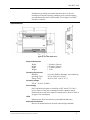
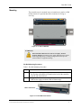
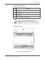
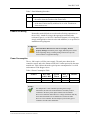
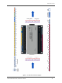
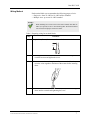
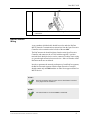
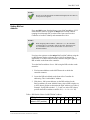
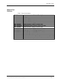
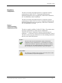
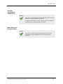
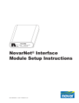
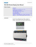
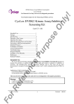
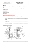
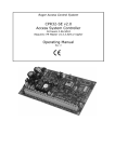
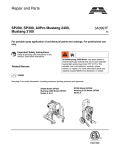
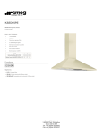
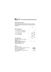
Part #RCC-1081
rcc.1081 BACnet® Case Controller
Mounting & Wiring Instructions
Table of Contents
Introduction ......................................................................................1
Specifications ...................................................................................2
Mounting ..........................................................................................3
Power & I/O Wiring.........................................................................5
Power Consumption .........................................................................5
Wiring Method .................................................................................7
BACnet Network Wiring .................................................................8
Setting BACnet Address ..................................................................9
Model & Part Numbers ..................................................................10
Regulatory Compliance .................................................................11
Introduction
Novar’s rcc.1081 BACnet® Case Controller consists of 10 user
configurable inputs and eight (8) outputs. The eight (8) outputs consist
of seven (7) form C relay outputs and one (1) pulse width modulated
solid state output plus one (1) 12VDC stepper motor output.
Figure 1. rcc.1081 BACnet Case Controller
The rcc.1081 is a multi-function controller that provides superheat
control when connected to EEV valves as well as suction pressure
regulation when connected to EEPR valves. The rcc.1081 can also
control display case and cold room ambient air temperatures and manage
defrost cycles for improved system energy consumption efficiencies.
RCC-1081-INS/B
For the latest technical documentation, visit www.novar.com/manuals
1
Part #RCC-1081
In addition to providing local control functions, the rcc.1081 will
continually monitor the operating conditions of its associated display
case and transmit the data via BACnet MS/TP to a higher level Opus®
Executive Controller.
Specifications
Figure 2. rcc.1081 Dimensions
Physical Dimensions
Width:
Height:
Depth:
Weight:
7.14 inches (181mm)
5.53 inches (141mm)
1.57 inches (40mm)
1.15 lbs
Operating Environment
Humidity:
Operating Temp:
Storage Temp:
5% to 95% Relative Humidity, non-condensing
32°F to 140°F (0°C to 60°C)
-40°F to 158°F. (-40° to 70° C)
Operating Voltage
22VAC - 28VAC, 50/60Hz
Power Supply
Power and universal inputs are classified as NEC Article 725 Class 2
(power limited.) Total power consumption of the controller and all
connected sensors and valves must be less than 100VA. Refer to Table 4
for typical VA consumption.
LEDs
Indicate power, BACnet connectivity and module health status
Safety and Precautions
Observe all national and local electrical codes during installation
RCC-1081-INS/B
For the latest technical documentation, visit www.novar.com/manuals
2
Part #RCC-1081
Mounting
The controller may be mounted in any orientation on a panel or a DIN
rail but must be in a position that allows clearance for wiring or
servicing.
Figure 3. rcc.1081 on DIN Rail
WARNING!
Electrical Shock Hazard! Can cause severe injury, death or
property damage. Disconnect power supply and load power sources
before beginning wiring or making wiring connections to prevent
electrical shock or equipment damage.
Din Rail Mounting Procedure
Table 1. Din Rail Mounting Procedure
Step
Procedure
1
Holding the controller with its top tilted in towards the DIN rail, hook
the top ridge of the DIN rail channel on the back of the controller
onto the top of the DIN rail.
Gently press down on the bottom half of the rcc.1081 to allow the
DIN latch to engage under the DIN rail bottom edge.
2
DIN Latch Release
Figure 4. rcc.1081 DIN Latch Release
RCC-1081-INS/B
For the latest technical documentation, visit www.novar.com/manuals
3
Part #RCC-1081
Din Rail Un-Mounting Procedure
Table 2. DIN Rail Un-Mounting Procedure
Step
Procedure
1
Remove all wiring connectors from the controller to expose DIN latch
release
Pull down DIN latch release with one hand to release the fastener
from the DIN rail.
Lift the bottom of the controller away from the DIN rail with your
other hand.
Unhook the top ridge of the DIN rail channel on the back of the
controller from the top of the DIN rail.
2
3
4
NOTE!
Please use caution when pulling the DIN latch release! Over
extending the DIN latch release can damage the resistance spring of
the mechanism.
Panel Mounting Procedure
Figure 5. rcc.1081 Mounting Hole Dimensions
RCC-1081-INS/B
For the latest technical documentation, visit www.novar.com/manuals
4
Part #RCC-1081
Table 3. Panel Mounting Procedure
Step
1
2
Procedure
Position the base of the product level against the panel wall and mark
the wall to show the location of the corner holes.
The controller mounts using four screws inserted through the corners
of the base. Fasten securely with four No. 6 or No. 8 machine or
sheet metal screws.
Power & I/O Wiring
Removable terminal blocks are used to make all wiring connections to
the rcc.1081. Attach all wiring to the appropriate terminal blocks
(reference Figure 6. rcc.1081 I/O Connection Diagram). All wiring must
comply with applicable electrical codes and ordinances, or as specified in
installation wiring diagrams.
WARNING!
Electrical Shock Hazard! Can cause severe injury, death or
property damage. Disconnect power supply and load power sources
before beginning wiring or making wiring connections to prevent
electrical shock or equipment damage.
Power Consumption
The rcc.1081 requires a 24Vac power supply. The total power draw for the
controller, sensors and valves cannot exceed 100 VA when powered by the same
transformer. Table 4 below shows the typical power consumption for a rcc.1081
and common 12Vdc Stepper valves.
Table 4. Power Consumption Table
Product
RCC-1081
w/RCC-RUI
Sporlan
CDS-8
CDS-9, 17
and 17
SEI/EEV
Typical VA Draw
< 10VA
10VA
5VA
10VA
NOTE!
For multiple RCC-1081 controllers operating from a single
transformer, the same side of the transformer secondary must be
connected to the same power input terminal on each controller.
RCC-1081 controllers utilize half-wave voltage rectification and may
not be mixed with full-wave rectified devices such as the older
RCC-521 Case Controller. Do not attempt to power both types of
controllers from the same transformer.
RCC-1081-INS/B
For the latest technical documentation, visit www.novar.com/manuals
5
Part #RCC-1081
Figure 6. rcc.1081 I/O Connection Diagram
RCC-1081-INS/B
For the latest technical documentation, visit www.novar.com/manuals
6
Part #RCC-1081
Wiring Method
Each terminal block can accommodate the following gauges of wire:
— Single wire: from 22 AWG to 14 AWG solid or stranded
— Multiple wires: up to two 18 AWG stranded
NOTE!
When attaching two or more wires to the same terminal, other than 14
AWG (2.0 sq mm), be sure to twist them together. Deviation from this
rule can result in improper electrical contact.
Table 5. Preparing wiring for terminal blocks
Step
1
Procedure
Strip 1/2 in. (13 mm) from wires to be attached at one terminal.
½”
2
Cut a single wire to 3/16 in. (5 mm). Insert the wire in the required
terminal location and tighten the screw.
3
If two or more wires are being inserted into one terminal location,
twist the wires together a minimum of three turns before inserting
them.
4
Cut the twisted end of the wires to 3/16 in. (5 mm) before inserting
them into the terminal and tightening the screw.
RCC-1081-INS/B
For the latest technical documentation, visit www.novar.com/manuals
7
Part #RCC-1081
5
Pull on each wire in all terminals to check for good mechanical
connection.
BACnet Network
Wiring
A two-conductor shielded cable should be used to make the BACnet
MS/TP Network Communications connections from the Opus Executive
Controller to the terminals on the left side of the rcc.1081.
The BACnet network should originate from the main Opus Executive
Controller and connect to the rcc.1081 with the supplied 5- position
terminal block. Multiple devices can be connected via daisy chain wiring
or a pass-through connection between devices. Stubs or branches off the
BACnet network are not allowed.
In order to guarantee the network performance of each BACnet segment,
the BACnet network segments from the Opus Executive Controller
should contain only rcc.1081 modules or other Novar approved BACnet
MS/TP devices.
NOTE!
Network termination and/or biasing resistors should NOT be applied
to any Opus BACnet installation.
NOTE!
The default baud rate for the rcc.1081 is 38400 baud.
RCC-1081-INS/B
For the latest technical documentation, visit www.novar.com/manuals
8
Part #RCC-1081
NOTE!
Do not exceed the maximum recommended length (1200 M / 4000 ft.)
for any BACnet segment.
Setting BACnet
Address
Every rcc.1081 comes from the factory set to a BACnet address of 255.
Each controller must be assigned an unique BACnet MAC address
(ranging from 4 through 254) in order for the Opus xcm Executive
Controller to be able to identify and communicate with it.
NOTE!
When assigning a MAC address – addresses 0, 1, 2, & 3 should be
avoided as they are commonly used for the router, diagnostic tools
etc, and addresses 255 is never used because it is reserved as a
broadcast address.
Users have the option to set the unique BACnet MAC address using the
rcc.RUI Remote display (reference the rcc.1081 User Manual for
instructions) or it can be entered into the controller using the eight (8)
DIP switches on the front of the controller.
To set the BACnet address of a rcc.1081 using the DIP switches on the
controller:
1. Find an unused address on the MS/TP network to which the
controller connects.
2. Locate the DIP switch bank on the front of the Controller for
addressing. This is labeled MAC Address
3. With the rcc.1081 powered down, set the DIP switches for the
BACnet address you want. Add the binary value of DIP switches set
to OFF (down) position to determine the MAC address (see Table 6).
Example: if only DIP switches 1, 3, 5, and 7 are in the OFF (down)
position the BACnet address would be 85 (1 + 4 + 16 + 64 = 85).
Table 6. DIP Switch Values for MS/TP MAC Address
DIP Switch #
VALUE
(when in OFF position)
1
2
3
4
5
6
7
8
1
2
4
8
16
32
64
128
RCC-1081-INS/B
For the latest technical documentation, visit www.novar.com/manuals
9
Part #RCC-1081
Model & Part
Numbers
Table 7. Novar Part Numbers
Part No.
RCC-1081
RCC-RUI
RCC-CBL-2
RCC-CBL-5
RCC-SP150-2
RCC-SP150-5
RCC-SP150-M
RCC-SP300-2
RCC-SP300-5
RCC-SP300-M
RCC-ST2K-2
RCC-ST2K-5
RCC-ST2K-8
RCC-ST2K-8-TJ
709031000
730090000
Product Description
Refrigeration Case/Circuit Controller Module
Remote Display
Remote Display Cable, RJ45, 2 meters
Remote Display Cable, RJ45, 5 meters
Sensor, Pressure, 150psig, w/2 meter Cable
Sensor, Pressure, 150psig, w/5 meter Cable
Replacement Sensor, Pressure, 150psig, No Cable
Sensor, Pressure, 300psig, w/2 meter Cable
Sensor, Pressure, 300psig, w/5 meter Cable
Replacement Sensor, Pressure, 300psig, No Cable
Sensor, Temperature, 2K NTC, w2 meter Cable
Sensor, Temperature, 2K NTC, w5 meter Cable
Sensor, Temperature, 2K NTC, w8 meter Cable
8 meter 2K Thermistor temperature probe with removable probe tip
Two-conductor shielded cable, RS-485 (1000 foot reel)
24-VAC Transformer (40 VA)
RCC-1081-INS/B
For the latest technical documentation, visit www.novar.com/manuals
10
Part #RCC-1081
Regulatory
Compliance
This device has been tested and found to be in compliance with the
requirements set forth in UL 873, Temperature-Indicating and
Regulating Equipment, and is recognized by Underwriters Laboratories,
Inc., for installations in the United States.
This device has been tested and found to be in compliance with the
requirements set forth in C22.2, No. 24-93, Temperature-Indicating and
Regulating Equipment, and is recognized by Underwriters Laboratories,
Inc., for installations in Canada.
Federal
Communications
Commission (FCC)
This device complies with Part 15 of the FCC Rules. The product meets
emissions requirements for product specific standards EN
55022/FCC/IC, Class A. Operation is subject to the following two
conditions: (1) This device may not cause harmful interference, and (2)
This device must accept any interference received, including interference
that may cause undesired operation.
NOTE!
This device has been tested and found to comply with the limits
established for Class A digital devices. It is intended to be used in a
commercial environment. Operation of this equipment in residential
environments may cause harmful interference, in which case the user
may be required to correct the interference at their own expense.
CAUTION!
Any changes or modifications not expressly approved by Novar could
void your authority to operate this equipment.
RCC-1081-INS/B
For the latest technical documentation, visit www.novar.com/manuals
11
Part #RCC-1081
Canadian
Department of
Comms (DOC)
NOTE!
This Class A digital apparatus meets all requirements of the Canadian
Interference-Causing Equipment Regulations.
Cet appareil numerique de la Classe A respecte toutes les exigencies
du Reglement sur le material broilleur du Canada.
Waste Electrical &
Electronic Equip
NOTE!
Customers are advised to dispose of this product at the end of its
useful life according to applicable local laws, regulations, and
procedures.
RCC-1081-INS/B
For the latest technical documentation, visit www.novar.com/manuals
12
Part #RCC-1081
Opus® is a Registered Trademark of Honeywell International
BACnet® is a registered trademark of American Society of Heating, Refrigerating and Air-Conditioning Engineers (ASHRAE)
The material in this document is for information purposes only. The content and the product it describes are subject to change
without notice. Novar makes no representations or warranties with respect to this document. In no event shall Novar be liable for
technical or editorial omissions or mistakes in this document, nor shall it be liable for any damages, direct or incidental, arising out of
or related to the use of this document. No part of this document may be reproduced in any form or by any means without prior
written permission from Novar.
Copyright © 2015 by Honeywell International, Inc. All Rights Reserved.
Novar
6060 Rockside Woods Blvd.,
Cleveland, OH 44131
Phone: 1.800.348.1235
www.novar.com
RCC-1081-INS/B
For the latest technical documentation, visit www.novar.com/manuals
13