1
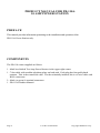
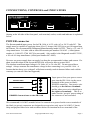
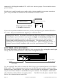
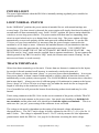
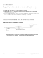
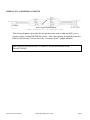
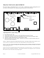
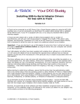
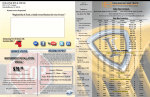
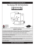
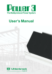
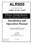
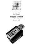
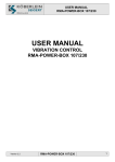
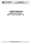
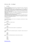
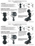
POWERHOUSE
TM
-- the finest in Digital Command Control --
PRODUCT MANUAL
FOR
PB-110A TEN AMP
POWER STATION
NCE Corporation
1260 CREEK STREET Suite 105
WEBSTER NEW YORK 14580
FAX : (716) 671-9337
E-mail: [email protected]
Last Revised 03/05/01
Copyright 1996-2000 NCE Corp.
1
PRODUCT MANUAL FOR PB-110A
10 AMP POWER STATION
PREFACE
This manual provides information pertaining to the installation and operation of the
PB-110A Power Station only.
COMPONENTS
The PB-110 comes supplied as follows:
1 - black box labeled Ten Amp Power Booster in the upper right corner.
1 - 7 foot cable with modular telephone plugs on both ends. Each plug has four gold-plated
contacts. This is the control bus cable. For the technically inclined, this is a 4-wire cable with
RJ-H connectors.
2 - black (or green) 4 terminal connectors
1 - PB-110A Product Manual.
Page 2
Last Revised 03/05/01
Copyright 2000NCE Corp.
CONNECTIONS, CONTROLS and INDICATORS
TEN AMP POWER BOOSTER
POWERHOUSE
FROM
NCE Corporation
CONTROL BUS
NORMAL
POWER
POWER
STATUS
TRACK
LOOP
22VAC/32VDC MAX.
PB110A
Starting at the left side of the front panel, each terminal, socket, switch and indicator is explained
below:
POWER connector
The Recommended input power for the PB-110A is 16-22 volts AC or 24-32 volts DC. The
supply must be capable of supplying about 10 to 12 Amps (180-250VA) to get full output from
the booster. We recommend the Hammond Manufacturing model 165T22. This is a 22 volt 12
Amp transformer. It is also sold as Allied Electronics part number 836-6185. (Allied phone
number is 1-800-433-5700 MC/Visa accepted). Also usable is the Magnetek model F-259U,
a 20 volt 10 Amp transformer (Allied part number 967-8442).
Do not a use power supply that can supply less than the recommended voltage and current. If a
short circuit develops on the layout the PB110A will not be able to protect itself.
The absolute maximum input voltage is 24 Volts AC or 36 volts DC. Do not exceed these
ratings! Always measure the transformer voltage before connecting it to your PB-110A. A
booster that has been ‘over voltaged’ will almost certainly result in booster failure and void the
warranty (we can tell if this has happened).
POWER WIRE
POWER WIRE
POWER Connections to the PB110A
Input power from your power source
goes into the PB-110A via the screw
terminals of the green (or black)
POWER connector. One power wire
should go to the left two terminals
and the other power wire should go to
the right two terminals. This is to
make sure the “per pin” power rating of
the connector is not exceeded.
We recommend #14 AWG stranded wires for connection to power but the screw terminals of
the black (or green) connectors are designed to accept wires only up to #16 AWG (1.3mm).
Strip and prepare forked wire ends as shown below for insertion in to two terminals of the
Last Revised 03/05/01
Copyright 2000 NCE Corp.
Page 3
connector by dividing the strands of #12 or #14 wire into two groups. Do not tin the wires to
prevent fraying.
If solid wire is used for track power, make a splice joint to stranded wire at some convenient
place. Only stranded wire should enter the terminals for reliable contact.
BARE STRANDED WIRE
INSULATION
Preparing wire for TRACK
or POWER Connectors
¼“
If you wish to purchase additional connectors you may use Digi-Key part number ED1962 or
277-1163. They are available from Digi-Key at 1-800-344-4539.
IMPORTANT NOTE: If you have more than one PB-110A, PB105, Powerhouse-Pro,
or any Digitrax power booster in your system we highly recommend grounding all the
power boosters together (except for any PB110A boosters used in “loop” mode) at a
central earth ground point such as a cold water pipe. You can use one of the cover
mounting screws as the ground point on your PB-110A. Failure to do this may result in
voltages at power district boundaries that exceed the specifications of DCC decoders.
CONTROL BUS SOCKETS
The control bus sockets on the front of the PB-110A are paired to allow wiring the control signal
coming from the command station to “daisy chain” through the booster.
FIVE AMP POWER BOOSTER
POWERHOUSE
NCE Corporation
FROM
CONTROL BUS
POWER
TRACK
18VAC/28VDC MAX.
LOOP
STATUS
NORMAL
To Other
Power Boosters
From Command
Station
7 Foot cable
Use the supplied 7 foot cable to connect the PB-110A to your command station’s CONTROL
BUS socket. The remaining (unused) socket on the PB-110 can be used to connect to other
boosters in daisy chain fashion. Use only the 4-wire RJ-H cable for this purpose. Longer cables
may be used if more distance is needed between power stations. The last power station at the
end of the daisy chain will have one empty socket.
The PB-110A will place a nominal 10mA
load on the command station control bus.
Page 4
Last Revised 03/05/01
Copyright 2000 NCE Corp.
POWER LIGHT
The power light indicates when the PB110A is internally making regulated power suitable for
normal operations .
LOOP/NORMAL SWITCH
In the “NORMAL” position, the power station is intended for use with normal trackage not
reverse loops. If a short circuit is detected, the power station will simply shut down for about 2-3
seconds and will then automatically reset. In the “LOOP” position, the power station should be
wired to a reverse loop power district. The power station will then sense an impending short
circuit as metal wheels arrive at or depart from the reverse loop. The power station will then
automatically reverse track polarity and the train proceeds without hesitation. To use the PB110A as a reverse loop controller it is necessary that the power booster connected to the
mainline be of 10 Amps or more. Otherwise the mainline booster will just shutdown when the
locomotive crosses the gaps into the 10 Amp powered reverse loop. YOU NEED TWO
BOOSTERS TO MAKE USE OF THE AUTOMATIC REVERSE LOOP FEATURE. Any
PB110A used in “loop” mode must be supplied from a separate transformer. Do not connect the
chassis ground of any PB110A used in “loop” mode, the booster must remain “floating” for the
auto-reverse feature to work correctly.
TRACK TERMINALS:
Wires from these terminals go to the track. If more than one booster is connected to the layout,
be sure the left track terminal on all boosters is consistently wired to the same rail.
This will ensure you have the same “phase” as you cross power district boundaries. In a reverse
loop power district, it doesn’t matter which terminal is wired to what rail since the booster will
automatically reverse polarity when required. The LOOP/NORMAL discussion above describes
this in more detail. Always use wire of sufficient gauge (#14 minimum) to connect to the layout.
Power “drops” of #18 or #20 wire to a larger wire bus under the track are fine as long as the
length of each drop to the main bus is less than 12”.
Use of a smaller bus will prevent the booster from detecting a short circuit and may be a fire
hazard.
Track wiring connects to the PB-110A via the screw terminals of the green (or black) TRACK
connector in the same manner as the power wires. One track wire should go to both the left
two terminals and the other track wire should go to both the right two terminals. This is to
make sure the “per pin” power rating of the connector is not exceeded.
The voltage to the track is dependent on the setting of the internal voltage adjustment, as
discussed above. The DCC track voltage is factory adjusted to the 16.0 (+/- 0.1) volts for O
and G Scales. The voltage is adjustable from 11.5 to 22 volts by means of a blue adjustment
potentiometer inside the PB110A. See page 8 for directions on setting the track voltage.
Last Revised 03/05/01
Copyright 2000 NCE Corp.
Page 5
STATUS LIGHT
This light will illuminate light steadily under normal operations. Flashing indicates an abnormal or
fault condition. Here is a description of the various conditions indicated by the status light.
⇒ Steady on - Track power is on and operations are normal.
⇒ Rapid flash - No DCC signal from command station (control bus cable is unplugged,
programming track in use, etc.)
⇒ Slower steady flash - Short Circuit (over current shutdown). The booster will shut down
for 2-3 seconds or until short or load of over 10.05 Amps is removed.
CONNECTING THE PB-110A TO OTHER SYSTEMS
WIRING TO A LENZ COMMAND STATION
Lenz LZ100
To PB105
Lenz to PB105 Booster cabling
This wiring diagram is provided for the operators that have switched from an Existing
LENZ system to NCE boosters. Lenz does not provide a ground point.
Page 6
Last Revised 03/05/01
Copyright 2000 NCE Corp.
WIRING TO A DIGITRAX SYSTEM
To PB105
NCE to Digitrax Booster cabling
This wiring diagram is provided for the operators that wish to add and NCE power
booster to their existing DIGITRAX system. This cable splicing is required to the first
DB100/150/200 only. Always leave the “Ground to Sync” Jumper installed.
Don’t forget to ground the PB-110 chassis to the ground terminal of the
DB100/150/200.
Last Revised 03/05/01
Copyright 2000 NCE Corp.
Page 7
TRACK VOLTAGE ADJUSTMENT
The track voltage is adjustable from 11.5 to 22 volts. Adjustment requires opening the case of
the booster and turning the blue adjustment potentiometer(s) as shown below.
DCC Voltage
Adjustment Pot
GROUND
VREG
measurement
location
Adjusting the DCC output voltage:
1)
2)
3)
4)
5)
Set voltmeter to DC volts
Touch minus (black) lead of meter to the GROUND pad on the PC Board
Touch plus (red) lead of meter to the rectangular silver circuit board pad marked VREG
Turn DCC voltage adjustment pot to desired output voltage
Adjust all boosters to the same voltage. Otherwise you will see a speed variation when you
cross power district boundaries
NOTE 1: Adjust the voltage with no appreciable load on track. The output voltage will rise slightly as more
current is drawn to compensate for the drop in the output MOSFETs and associated wiring.
NOTE 2: If you have a means of measuring the track voltage (a typical “True RMS” reading meter will NOT be
able to read the track voltage) the voltage can be adjusted through a hole in the back of the PB-110A chassis
without opening the cover.
NOTE 3: We do not recommend setting the track voltage above 16 volts for O-Scale. It is very hard on any
lights you may have installed in locomotives. Most O-Scale locomotives are designed to run on 14.25 Volts
DCC (about 12 volts to the motor) for prototype speed.
Page 8
Last Revised 03/05/01
Copyright 2000 NCE Corp.