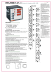
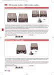
1
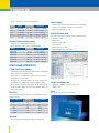
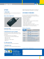
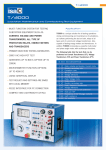
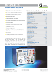
T 1000 PLUS
Secondary Injection Relay Test Set
•
• Microprocessor controlled
• With phase angle shifter
• Frequency generator
• Test results and settings are saved into local memory
• High power outputs
• Oscilloscope function for current and voltage
• Large graphical display
• Compact and lightweight
• Possibility to synchronize several T 1000 PLUS test sets
• USB and RS232 interface
• 2 auxiliary contacts for the test of autoreclosers
Designed for testing relays and transducers
A
P
P
L
I
C
A T
I
O
N
The relay test set T 1000 PLUS is suited for the
testing of the following types of relays:
RELAY TYPE
Distance relay (3 sets)
Synchronizing device
Under/over-voltage relay
Directional Power relay
Field relay
Reverse phase current relay
Phase sequence voltage relay
Incomplete sequence relay
Instantaneous over-current relay
Inverse time over-current relay
Power factor relay
Voltage balance relay
Ground detector relay
Directional over-current relay
Phase angle out of step relay
Automatic reclosing relay
Frequency relay
Pilot wire receiver relay
Lockout relay
Differential protection relay
Voltage directional relay
Power directional relay
Tripping relay
IEEE NO
21
25
27/59
32
40
46
47
48
50
51
55
60
64
67
78
79
81
85
86
87
91
92
94
Note: WINDOWS is a trademark of MICROSOFT inc.
1
T 1000 PLUS
The instrument contains three separate generators:
. Main generator, that generates either AC current, AC
voltage; DC voltage;
. Auxiliary AC voltage generator, that generates an
independent, phase shiftable AC voltage;
. Auxiliary DC voltage generator, that generates the DC
voltage that powers the relay under test.
All outputs are adjustable and metered at the same time on the
large, graphic LCD display.
T 1000 PLUS can operate without connection to a PC. With the
multi-purpose knob and the LCD display it is possible to enter
the MENU mode, that allows to set many functions, that make
T 1000 PLUS a very powerful testing device, with manual and
semi-automatic testing capabilities, and with the possibility to
transfer test results to a PC via USB or RS232 interface. These
results can be recorded, displayed and analysed by the powerful TDMS software, that operates with all WINDOWS versions,
starting from WINDOWS 98 included.
T 1000 PLUS Specification
Main generator
The main generator has three outputs: currents, voltage AC,
voltage DC. The following specifications apply to the separate
usage of these outputs.
AC current outputs
RANGE CURRENT
A
OUTPUT
AC
A
100
40
10
30
100
250
12
40
5
10
MAXIMUM
POWER
VA
300
800
1000
300
800
400
800
LOAD
TIME
s
steady
60
1
steady
60
steady
60
RECOVERY
TIME
min
15
5
15
15
DC voltage outputs
RANGE VOLTAGE
V
OUTPUT
DC
V
300
300
300
MAXIMUM
POWER
W
LOAD
TIME
s
300
500
RECOVERY
TIME
min
steady
10
45
Other features of main outputs
. Zero crossing control. Main AC outputs are generated and
stopped as the output waveform crosses zero.
. High resolution adjustment control.
. Overload alarm message.
. Thermal protection.
. Possibility to reduce the output power to one fifth for low burdens.
Auxiliary AC voltage output
. The auxiliary AC voltage output is isolated from the main
AC current and voltage.
. Range selection: software driven, by the multi-function knob
and LCD display.
. Auxiliary voltage power: 30 VA, continuous duty, at full
range; 40 VA for 1 minute.
. Push-button to enable or disable the output
Auxiliary AC voltage output
RANGE V
62.5
125
250
MAX POWER VA
40
40
40
Phase angle shifting
. Possibility to phase shift the auxiliary AC voltage output
with respect to the main current or voltage.
. Phase angle adjustment: via the multi-function knob.
. Phase angle range: from 0° to 360°.
. Adjustment resolution: 1° (degree).
Frequency generator & frequency r.o.c.
AC voltage outputs
RANGE VOLTAGE
V
OUTPUT
AC
V
250
2
250
250
MAXIMUM
POWER
VA
500
750
LOAD
TIME
s
steady
10
RECOVERY
TIME
min
45
. Possibility to change the frequency of the auxiliary AC
voltage output. Frequency generation characteristics:
. Frequency range: 40 Hz to 500 Hz.
. Frequency adjustment: 1 mHz.
. Rate of change: 1 mHz/s to 99.99 Hz/s.
T1000 PLUS S
T2000 T
T
ECONDARY INJECTION
RANSFORMER EST
RELAY TEST SET
SET
Auxiliary DC voltage output
Voltage measurement
. DC voltage range: 10...130 V or 20...240 V.
. DC voltage power: 90 W at full range, continuous duty,
with a current limit of 0.9 A @ 130 V and 0.45 A @ 240 V.
. Push-button to enable or disable the output
OUTPUT
Timer
The electronic digital timer has a fully automatic start and stop,
both for make and break of the input, that can be either a clean
(dry) contact or a contact under voltage (wet).
. Metering range, can also be performed in cycles.
RANGE
From 0 to 9.999 s
From 10.0 to 99.99 s
From 100.0 to 999.9 s
From 1.000 to 9.999 s
RESOLUTION
ACCURACY
1 ms
10 ms
100 ms
1s
± (1 ms + 0.005%)
± (10 ms + 0.005%)
± (100 ms + 0.005%)
± (1 s + 0.005%)
. Possibility to test automatic reclosers.
. Maximum number of reclosing commands: 99.
RANGE
250 V AC
19.99 V
199.9 V
299.9 V
300 V DC 19.99 V
199.9 V
399.9 V
65,130 V AC 19.99 V
199.9 V
260 V AC 19.99 V
199.9 V
299.9 V
130 V DC 19.99 V
199.9 V
260 V DC 19.99 V
199.9 V
299.9 V
RESOLUTION
10
100
300
10
100
300
10
100
10
100
300
10
100
10
100
300
mV
mV
mV
mV
mV
mV
mV
mV
mV
mV
mV
mV
mV
mV
mV
mV
ACCURACY
± (1% + 50 mV)
± (1% + 200 mV)
± (1% + 300 mV)
± (0.5% + 50 mV)
± (0.5% + 200 mV)
± (0.5% + 300 mV)
± (1% + 20 mV)
± (1% + 200 mV)
± (1% + 20 mV)
± (1% + 200 mV)
± (1% + 300 mV)
± (0.5% + 20 mV)
± (0.5% + 200 mV)
± (0.5% + 20 mV)
± (0.5% + 200 mV)
± (0.5% + 300 mV)
Angle and frequency measurement
. Via the multi-function menu knob it is possible to select the
measurement of angle or frequency.
. Readings, resolution and accuracy: see table.
2 auxiliary contacts are available
. Contacts range: 5 A; 250 V AC; 120 V DC.
OUTPUT CURRENT AND VOLTAGE
MEASUREMENTS
MEASUREMENT RANGE
Phase
Frequency
0-360
40.000-499.999
RESOLUTION ACCURACY
1°
1 mHz
1° ± 1 Digit
±(0.1% + 1 mHz)
. The following outputs are displayed at the same time on the LCD:
Other measurements
Current measurement
OUTPUT
10 A
40 A
100 A
RANGE
1.999 A
19.99 A
7.999 A
79.99 A
19.99 A
199.9 A
249.9 A
MEASUREMENT
RESOLUTION
1
10
4
40
10
100
100
mA
mA
mA
mA
mA
mA
mA
ACCURACY
± (1% + 5 mA)
± (1% + 20 mA)
± (1% + 20 mA)
± (1% + 80 mA)
± (1% + 50 mA)
± (1% + 200 mA)
± (1% + 200 mA)
Active Power, P = I*V*cos (j)
Reactive Power, Q = I*V*sin(j)
Apparent Power, S = I*V
Impedance, Z = V/I
Active Impedance Component, R = Z* cos(j)
Reactive Impedance Component, X = Z* sin(j)
UNIT
W
VAr
VA
Ohm, °
Ohm
Ohm
External inputs measurement
. It is possible to meter current or voltage input.
External current measurement
. Two inputs: 20 mA and 10 A.
3
T 1000 PLUS
Power supply
. Range, resolution, accuracy: see table below.
INPUT
20 mA
10 A
10 A
10 A
10 A
RANGE
0.02 A DC
1.999 A AC
9.99 A AC
1.999 A DC
9.99 A DC
RESOLUTION
0.1
1
10
1
10
mA
mA
mA
mA
mA
ACCURACY
± (0.5% + 0.1 mA)
± (1% + 2 mA)
± (1% + 20 mA)
± (0.5% + 2 mA)
± (0.5% + 20 mA)
External voltage measurement
. Maximum input voltage: 600 V, AC or DC.
. Range, resolution and accuracy: see table below.
RANGE
9.999 V AC
99.99 V AC
599.9 V AC
9.999 V DC
99.99 V DC
599.9 V DC
RESOLUTION
2
10
100
2
10
100
mV
mV
mV
mV
mV
mV
ACCURACY
. Mains supply to be clearly indicated in purchase order:
230 V ± 15% 50-60 Hz or 120 V ± 15%50-60 Hz
. Maximum supply current: 5 A.
Standard accessories
The instrument comes complete with the following items:
. Set of test cables;
. Mains cable;
. RS232 and USB cable;
. User’s manual;
. Spare fuses (no. 5), T5A.
. Software TDMS with serial cable.
± (1% + 10 mV)
± (1% + 20 mV)
± (1% + 200 mV)
± (0.5% + 10 mV)
± (0.5% + 20 mV)
± (0.5% + 200 mV)
OTHER CHARACTERISTICS
T 1000 PLUS local memory
. Test settings can be stored and recalled from the T 1000 PLUS
local memory: up to 10 test settings.
. Test results can be saved into a permanent local memory:
up to 500 test results saved.
. When the PC is connected setting can also be created and
transferred into T 1000 PLUS using the software TDMS.
. When the PC is connected test results can be transferred to
the PC via USB or RS232 port using the software TDMS, for
saving and printing.
POWER W
50
50
50
50
50
50
MAX CURRENT A
10
7
2.15
0.33
0.22
0.15
interface
. Interfaces for connection to PC: USB and serial RS232.
4
. Dimensions: 380 (w) x 300 (d) x 240 (h) mm.
. Weight: 19 kg.
Alluminium case with cover and handle.
A set of resistors is supplied for the test of low impedance relays.
Available values:
0,5
1
22
470
1000
2200
Weight and dimension
Case
Resistors
RESISTANCE OHM
TDMS - Relay Test Result
T1000 PLUS S
T2000 T
T
ECONDARY INJECTION
RANSFORMER EST
RELAY TEST SET
SET
OPTIONS
Maximum output power becomes 20 VA. The auxiliaru DC
voltage is removed. Other characteristics are unchanged.
T 1000 E PLUS
In this model, maximum main and auxiliary AC voltages are
500 V instead of 250 V.
Heavy duty transport case
APPLICABLE STANDARDS
The test set conforms to the EEC directives regarding
Electromagnetic Compatibility and Low Voltage instruments.
A) Electromagnetic Compatibility:
Directive no. 2004/108/EC
B)Low Voltage Directive:
Directive n. 2006/95/EC.
Applicable standards, for a class I instrument, pollution
degree 2, Installation category II:
. CEI EN 61010-1. In particular:
. Inputs/outputs protection: IP 2X - CEI 70-1.
. Operating temperature: 0 to 50°C; storage: -40°C to 70°C.
. Relative humidity: 10 - 80% without condensing.
Ordering information:
Connection cables
The kit includes 17 cables in all, for any kind of connection.
CODE
D 1000 Differential relay test module
91093
The differential relay test module D 1000 allows the test of
the differential relay curve and also of the harmonic restraint
characteristic.
The module performances are the followings:
. Input: from the test set auxiliary AC voltage output.
. Output: 0 to 5 A CA.
. Output power: 5 VA.
. Dimension: 325 x 290 x 290 mm.
. Weight: 7 kg.
81093
30093
71093
17093
18093
40093
41024
MODULE
T 1000 PLUS
T 1000 PLUS complete with Software
TDMS - 220V
T 1000 PLUS complete with Software
TDMS - 120V
T 1000 E PLUS (500V Aux Voltage outputs) 220 V complete with Software TDMS
T1000 PLUS 15 Hz
Heavy Duty Transport Case
Set of test cables for models T 1000 PLUS
D 1000 differential relay test module
FT 1000 PLUS Mains Filter Unit
FT 1000 current filter
This external module removes AC current distortions.
T 1000 PLUS-15 Hz
ISA Srl
Via Prati Bassi, 22
21020 Taino VA - Italia
Tel +39 0331 956081
Fax +39 0331 957091
Web site: www.isatest.com
E-Mail: [email protected]
The document is subject to change without notice.
GB - T 1000 PLUS - 10.08
In this model, the minimum auxiliary AC voltage frequency is
15 Hz.
5