1
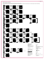
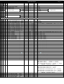
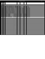
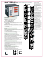
>>>> Page 1
MULTISER-01-PC Network Analyser (RS-485)
SET
Enter Pressing
for 3 Seconds
Increase
SET
Decrease
Increase
SET
Decrease
Increase
SET
Decrease
SPECIFICATIONS
Increase
■ Microprocessor based
■ Measurement of 3 phase electrical quantities
( VL-N, A, CosΦ, VL-L, Hz, W, VAr, VA
ΣW, ΣVAr, ΣVA, ΣWh, ΣVArh, ΣVAh)
■ 1-60 min. adjustable demand v alues
(VL-N, A, CosΦ, VL-L, W, VAr, VA)
■ Correct learning of current transf ormer polarity (ev en if (k,l) is connecte
in rev erse direction)
■ Setting of current and v oltage transf ormer ratios
■ Seperate or all together clearance of stored demand, peak and energy v alues
■ Easy access to menus
■ Reduces both number of measurement equipment used in the panel and
connection time
■ Lowers electrical panel costs
SET
Decrease
Increase
SET
Decrease
Increase
SET
Foreword
Decrease
All information and warnings about Network Analyser MULTISER are given in this User's Manual.
Please for your power network's and your own safety, read this manual carefully before commissioning
the system. Please contact us for unclear points.
KAEL Müh. Elektronik Tic ve San. Ltd Şti.
Atatürk mah. 78 sok. No:10 Büyükalan mevkii Ulucak/Kemalpasa -IZMIR – TÜRKİYE
Tel: +90-232-8771484, email: [email protected], web: www.kael.com.tr .
SET
ACCESSING PARAMETERS:
Using the direction buttons, it is pos sible
to move up and down in the menu. W hen
set button is pressed down for 3 sec onds,
parameter setting menu is accessed and
T o set any of the parameters, first set
button is pressed, then using the directions
buttons, value is increased/decreased.
When desired value is reached, it is stored
by pres sing the set button. Using the
direction buttons.
Ct: Current transformer v alue : (5...10000)
T he current tranformer's primary value
should be entered. For example if 500/5A
current isused then 500 must be entered.
Ut: Voltage transformer v alue : (1...1000)
If no voltage transformer is us ed, this
parameter must be left as 1.
denn tınE : Demand time : ( 5-60 min)
Demand time parameter, determines the
calculation period of demand and peak
values .
YOn Lrn: Current transformer polarity
direction learning: ( on – oFF)
If it is “ on ” then the device would learn the
direction automatically. If the device monted
in new panel or the polarity somehow
changed then it learns the new direc tion.
If off then the device would learn the
direction once and never learn it again.
Off pos ition is required for some loads.
If there would be a problem in the surrent
transformer direction then the current
transformer inputs shuld be switched.
SAYC tYPE : Counter type : ( nor-ELEC )
nor: Energies are calc ulated due the vectorial
sum of the phases.
ELEC: Energies are calculated for each
phase separately.
dEv no : device number ( 1 - 255 )
CLr: To clear demand, peak and
enegy v alues:
placed where the stored values like demand,
peak values and energies are cleared.
Values can be cleared either separately or all
together, from ALL section, under this menu.
In order to clear the stored values SET
buttonmust be pressed. T he following
parameters can be set:
CLr uL-n :Clears the demand and the peak
values of the phase-neutral voltages
CLr A
:Clears the demand and the peak
values of the c urrents
CLr uL-L :Clears the demand and the peak
values of the ğhase-phase voltages
CLr P
:Clears the demand and the peak
values of the active energies
CLr q
:Clears the demand and the peak
values of the reactive energies
CLr S
:Clears the demand and the peak
values of the apparent energies
CLr hr-- :Clears the stored active, reactive
and apparent energy s ums
CLr ALL : Clears all mentioned values
above
Note: If no button is pressed for 4 minutes
under this menu, device automatically quits
programming menu.
SET
Warnings:
clr.
1- The connection, operation and parameter settings of device must be done by authorised technical
service staff. Also, system checks must be done by this person when necessary.
2- Please do not open or do not let others open the device. There are no user serviceable parts inside.
3- Before making the connections to device's terminals, please be sure that there is no voltage
across the cables or terminals. Also be sure that the panel is de-energised.
4- Please fix the device to electric panel with apparatuses supplied.
5- Please press the buttons only by your fingers, do not contact anyother object with them.
6- Before cleaning the device, please be sure that it is de-energised and use only dry tissue-paper
to clean it. Water or any other chemicals used for cleaning may harm the device.
7- Before commissioning the device, please be sure that the terminal connections are made exactly
the same as in the connection diagram and avoid any connection problems, such as loose
connections or contact of different cables.
SET
clr.
SET
Exit
General
SET
Multiser gives the ability of tracking electrical parameters for 3 phase systems such as, phase
currents, phase-neutral & phase-phase voltages, frequency, power factor, active powers, reactive
powers and apparent powers. It also stores consumed energies. It also gives the opportunity of
tracking total, max. demand and peak values for stated quantities.Current and voltage transformer
ratios can be set by the user.
Using the directions buttons, desired parameters can be accessed easily. On the other hand, its
displays make it possible to track values from long distance.
Cleared
Installation Instructions :
1. A hole with 92mm x 92 mm must is needed on the panel for device installation
2. Remove the fixing apparatus before installing the device
3. Place the device in the prepared hole from the fromnt side.
4. Use the fixing apparatus to fix the device from the back side to the pannel.
CAUTION:
Leave at least 50mm space between the back side of the device and the internal wall of the pannel
Wall
for the airing purpose
80 mm
96 mm
92 mm
90 mm
Panel Hole Dimensions
71 mm
92 mm
50 mm
96 mm
SET
CLR Menu
>>>> Page 2
Measured Electrical Parameters
U 3N
I1
L2
I2
L3
I3
Current ( A )
P.F L1
PF 1
L2
PF 2
L3
PF 3
L1
U 12
L2
U 23
L3
U 31
f1
L2
f2
L3
f3
U 3N
V
L-N
A L1
I1
L2
I2
L3
I3
Peak ( A )
V
L-L
L1
U12
L2
U23
L3
U31
SET
L2
U2N
L3
U3N
I1
L2
I2
L3
I3
Max.Demand ( A )
P.F L1
PF 1
L2
PF 2
L3
PF 3
Ind.Peak (CosΦ)
SET
Peak ( V L-L )
SET
U1N
A L1
SET
Resultant (CosΦ)
SET
L1
Max.Demand ( V L-N )
SET
CosΦ
Voltage ( V L-L )
Hz L1
L3
Σ P.F
Peak
L-L
U 2N
SET
Power Factor (CosΦ)
V
L2
Peak ( V L-N )
SET
Peak
A L1
U 1N
V
L-L
L1
U12
L2
U23
L3
U31
SET
P.F L1
PF 1
L2
PF 2
L3
PF 3
Cap.Peak (CosΦ)
Max.Demand
L3
Voltage ( V L-N )
L1
SET
Max.Demand
U 2N
L-N
Peak
L2
V
Max. Demand
U 1N
Peak
L1
Max. Demand
L-N
Peak
V
Max. Demand
(VL-N, A, CosΦ, VL-L, Hz, W, VAr, VA, ΣW, ΣVAr, ΣVA, ΣWh, ΣVArh, ΣVAh )
These parameters can be reached using the direction buttons, with the related led on and with the measured v alues f or the three phases shown simultaneously .
Max.Demand ( V L-L )
SET
P.F L1
PF 1
L2
PF 2
L3
PF 3
Ind.Demand (CosΦ)
P.F L1
PF 1
L2
PF 2
L3
PF 3
Cap.Demand (CosΦ)
Frequency ( Hz )
W3
Active Power
W3
Σ Active Power
K
VAr L1
L2
M
SET
VAr2
c
Σ cap
i+c
Σ ind
Σi + Σ c
Σ Reactive Power
SET
K
M
VA L1
VA1
L2
VA2
Aparent Power
M
SET
W3
Peak (Active Power)
VA3
Σ Aparent Power
SET
SET
W L1
W1
L2
W2
L3
W3
Max.Demand (Active Power)
K
M
VAr L1
VAr1
L2
VAr2
L3
VAr3
Ind.Peak(Reactive Power)
M
VA1
VA2
SET
L3
K
Σ VA
VA3
L3
W2
M
i
Reactive Power
L2
K
VAr1 Σ VAr
VAr3
L3
M
L3
SET
Peak
M
W2
W L1
SET
K
VAr L1
L2
VAr2
L3
VAr3
Cap.Peak(Reactive Power)
K
M
VA L1
VA1
L2
VA2
L3
VA3
Peak (Aparent Power)
K
SET
VAr L1
VAr1
L2
VAr2
L3
VAr3
SET
Ind. Demand(Reactive Power)
K
M
VA L1
VA1
L2
VA2
L3
VA3
Max.Demand
(Aparent Power)
SET
Σ Wh
Σ Active Energy
M
K
M
Σ VAr
K
M
Σ VAr
Σ VArh
Σ VAr
Σ VArh
(İnd.)
(cap.)
hr
hr
Σ Ind.Reactive Energy
M
K
Σ VA
Σ VAh
Σ Apparent Energy
K
SET
Σ Cap.Reactive Energy
hr
SET
Σ Varhind + Σ VArh cap
Σ Reactive Energy
K
VAr L1
VAr1
L2
VAr2
L3
VAr3
Cap. Demand
(Reactive Power)
TECHNICAL DATA:
hr
K
M
VAr1
Σ W
hr
K
Max.Demand
L3
L2
M
W1
Max.Demand
W2
W L1
K
Max.Demand
L2
Σ
M
W1
Peak
W L1
K
Max.Demand
M
W1
Peak
K
Peak
M
Rated Voltage (Un)
Operating Range
Frequency
Supply Power Cons umption
Measurement Power Consumption
Voltage Measurement Range
:
:
:
:
:
:
230 VAC
(0.8 – 1.1)xUn
50 Hz
< 6 VA
< 1 VA
(Phase-Neutral)30-300 VAC, 45-90 Hz
(Phase-Phase) 30-600 VAC, 45-90 Hz
(Secondary current)
50mA – 6 Amp. AC
0 – 999.9 kV
0 – 999.9 M (W , VAr, VA)
(Cosφ) 0.00 – 1.00 ind. & cap.
50 mA, 30V
1% + digit
1 ......... 1000
5/5 ...... 10000/5 A
4 Digits LED display
Current Measurement Range
:
Display Range
:
Minimum Measurement Values
Measurement Sensitivity
Voltage T ransformer Ratio
Current T ransformer Ratio
Display
:
:
:
:
:
RS-485 (MODBUS-RTU)
Baud Rate
Parity
Device Number
: 9600 Kbps
: no parity
: 1 - 255
Measurement Category
Equipment Protection Clas s
Device Protection Class
Connector Protection Clas s
Ambient T emperature
Humidity
Connection T ype
Dimensions
:
:
:
:
:
:
:
:
CAT III
Double Insulation - class II (
)
IP20
IP00
-5°C....+50°C
15% ...... 95% (without condensation)
T o front panel tap
96x96x80 mm
REGISTER TABLE
PARAMETER
ADRES 1
(HEX )
ADRES 2
(HEX )
(R)read
(W)write
NO
FORMAT
MULTIPLIER
>>>> Page 3
UNIT
INSTRUCTION
1 0000 -----
R
COUNTRY CODE (TURKEY)
unsigned int
1
869
2 0001 -----
R
COMPANY CODE
unsigned int
1
7436
3 0002 -----
R
HW unsigned int
1
0x 0001
4 0003 -----
R
LW unsigned int
1
0x 59B2
5 0004 -----
R
BARCODE CONTROL
unsigned int
1
8
6 0005 -----
R
SOFTWARE VERSION
unsigned int
1
0x 0220
7 0006 -----
R/W DEVICE NUMBER
HW unsigned int
1
0x FFFF
-
0x 0000
8 0007 -----
R/W
LW unsigned int
1
0x FFFF
-
0x 0000
PRODUCT CODE
88498 decimal
INSTANTANEOUS VALUES
1 1000 E000 R
CURRENT TRANSFORMER RATIO (ATRF)
unsigned int
1
ATRF
1 - 2000
2 1001 E001 R
VOLTAGE TRANSFORMER RATIO
(GTRF)
unsigned int
0,1
GTRF
10 - 10000
3 1002 E002 R
PHASE 1 VOLTAGE Phase-Neutral
(VL1N )
unsigned int
0,1 x (GTRF)
VOLT
( (VL1N) x GTRF x 0,1); ex ample:If GTRF=1 ; 2200 x ( 1 x 0,1) = 220 Volt
4 1003 E003 R
PHASE 2 VOLTAGE Phase-Neutral
(VL2N )
unsigned int
0,1 x (GTRF)
VOLT
5 1004 E004 R
PHASE 3 VOLTAGE Phase-Neutral
(VL3N )
unsigned int
0,1 x (GTRF)
VOLT
6 1005 E005 R
PHASES 1-2 VOLTAGE Phase-phase (VL12 )
unsigned int
0,1 x (GTRF)
VOLT
7 1006 E006 R
PHASES 1-3 VOLTAGE Phase-phase (VL13 )
unsigned int
0,1 x (GTRF)
VOLT
8 1007 E007 R
PHASES 2-3 VOLTAGE Phase-phase (VL23 )
unsigned int
0,1 x (GTRF)
VOLT
9 1008 E008 R
PHASE 1 CURRENT
(I1)
unsigned int (ATRF) x 0,001 AMPER
(I1 x ATRF x 0,001); Ex ample:If 100/5A ; 5000 x ( 20 x 0,001) = 100 A
10 1009 E009 R
PHASE 2 CURRENT
(I2)
unsigned int (ATRF) x 0,001 AMPER
(I2 x ATRF x 0,001)
11 100A E00A R
PHASE 3 CURRENT
(I3)
unsigned int (ATRF) x 0,001 AMPER
(I3 x ATRF x 0,001)
(ATRF) x (GTRF)
12 100B E00B R
PHASE 1 ACTIVE POWER
(P1)
unsigned int
WATT
(P1 x (ATRF) x (GTRF) )
13 100C E00C R
PHASE 2 ACTIVE POWER
(P2)
unsigned int (ATRF) x (GTRF) WATT
(P2 x (ATRF) x (GTRF) )
14 100D E00D R
PHASE 3 ACTIVE POWER
(P3)
unsigned int
(ATRF) x (GTRF)
WATT
(P2 x (ATRF) x (GTRF) )
15 100E E00E R
PHASE 1 REACTIVE POWER
(Q1)
signed int
(ATRF) x (GTRF)
VAR
(Q1 x (ATRF) x (GTRF) )
16 100F E00F R
PHASE 2 REACTIVE POWER
(Q2)
signed int
(ATRF) x (GTRF)
VAR
(Q2 x (ATRF) x (GTRF) )
17 1010 E010 R
PHASE 3 REACTIVE POWER
(Q3)
signed int
(ATRF) x (GTRF)
VAR
(Q3 x (ATRF) x (GTRF) )
(ATRF) x (GTRF)
18 1011 E011 R
PHASE 1 APPARENT POWER
(S1)
unsigned int
VA
(S1 x (ATRF) x (GTRF) )
19 1012 E012 R
PHASE 2 APPARENT POWER
(S2)
unsigned int (ATRF) x (GTRF)
VA
(S2 x (ATRF) x (GTRF) )
unsigned int (ATRF) x (GTRF)
VA
(S3 x (ATRF) x (GTRF) )
20 1013 E013 R
PHASE 3 APPARENT POWER
(S3)
21 1014 E014 R
PHASE 1 COSØ
(COSØ1)
signed int
0,01
-
(COSØ1 x 0,01)
22 1015 E015 R
PHASE 2 COSØ
(COSØ2)
signed int
0,01
-
(COSØ2 x 0,01)
23 1016 E016 R
PHASE 3 COSØ
(COSØ3)
signed int
0,01
-
(COSØ3 x 0,01)
24 1017 E017 R
TOTAL COSØ
(COSØ)
signed int
0,01
-
(COSØ x 0,01)
unsigned int
(ATRF) x (GTRF)
WATT
signed int
(ATRF) x (GTRF)
VAR
0,1
Hz
25 1018 E018 R
TOTAL ACTIVE POWER
26 1019 E019 R
TOTAL REACTIVE POWER VECTOR
(ΣP)
27 101A E01A R
FREQUENCY
(f)
unsigned int
28 101B E01B R
TOTAL APPARENT POWER
(ΣS)
unsigned int (ATRF) x (GTRF)
(ΣQ)
VA
29 101C E01C R
REACTIVE POWER DIRECTION BITS
unsigned int
1
-
30 101D E01D R
CURRENT TRANSFORMERS DIRECTION BITS
unsigned int
1
-
31 101E E01E R
TOTAL INDUCTIVE POWER
(ΣQind)
signed int
(ATRF) x (GTRF)
VAR
32 101F E01F R
TOTAL CAPACITIVE POWER
(ΣQkap)
signed int
(ATRF) x (GTRF)
VAR
33 1020 E020 R
TOTAL REACTIVE POWER
(ΣQ)
unsigned int (ATRF) x (GTRF)
VAR
( (ΣP) x (ATRF) x (GTRF) )
(f x 0,1)
( (ΣS) x (ATRF) x (GTRF) )
Bit 0: Direction of phase 1 ( “1” = capacitiv e , “ 0” = inductiv e )
Bit 1: Direction of phase 2 ( “1” = capacitiv e , “ 0” = inductiv e )
Bit 2: Direction of phase 3 ( “1” = capacitiv e , “ 0” = inductiv e )
Bit 3: Direction of total reactiv e pow er ( “1” = capacitiv e , “ 0” = inductiv e )
NOT: Bit4,.......Bit15 reserv e READ “ 0”
Bit 0: Current direction of phase 1 (if it is “ 1” , rev erse)
Bit 1: Current direction of phase 2 (if it is “ 1” , rev erse)
Bit 2: Current direction of phase 3 (if is “ 1” , rev erse)
Bit 3: determination of current direction phase 1 (if it is “ 1” , determined)
Bit 4: determination of current direction phase 2 (if it is “ 1”, determined)
Bit 5: determination of current direction phase 3 (if it is “ 1” , determined)
NOT: Bit6,.......Bit15 reserv e READ ” 0”
PARAMETER
(R)read
(W)write
ADRES 1
(HEX )
ADRES 2
(HEX )
REGISTER TABLE
NO
FORMAT
MULTIPLIER
>>>> Page 4
UNIT
INSTRUCTION
DEMANDS
1 2000 ------
R
CURRENT TRANSFORMER RATIO (ATRF)
unsigned int
1
ATRF
1 - 2000
2 2001 ------
R
VOLTAGE TRANSFORMER RATIO
(GTRF)
unsigned int
0,1
GTRF
10 - 10000
3 2002 E021 R
PHASE 1 VOLTAGE Phase-Neutral
(VL1N )
unsigned int
0,1 x (GTRF)
VOLT
Demand Value
4 2003 E022 R
PHASE 2 VOLTAGE Phase-Neutral (VL2N)
unsigned int
0,1 x (GTRF)
VOLT
Demand Value
5 2004 E023 R
PHASE 3 VOLTAGE Phase-Neutral (VL3N)
unsigned int
0,1 x (GTRF)
VOLT
Demand Value
6 2005 E024 R
PHASES 1-2 VOLTAGE Phase-phase (VL12 )
unsigned int
0,1 x (GTRF)
VOLT
Demand Value
7 2006 E025 R
PHASES 1-3 VOLTAGE Phase-phase (VL13 )
unsigned int
0,1 x (GTRF)
VOLT
Demand Value
0,1 x (GTRF)
VOLT
Demand Value
8 2007 E026 R
PHASES 2-3 VOLTAGE Phase-phase (VL23 )
unsigned int
9 2008 E027 R
PHASE 1 CURRENT
(I1) demand
unsigned int (ATRF) x 0,001 AMPER Demand Value
10 2009 E028 R
PHASE 2 CURRENT
(I2) demand
unsigned int (ATRF) x 0,001 AMPER Demand Value
11 200A E029 R
PHASE 3 CURRENT
(I3) demand
unsigned int (ATRF) x 0,001 AMPER Demand Value
12 200B E02A R
PHASE 1 ACTIVE POWER
(P1) demand
unsigned int (ATRF) x (GTRF) WATT
Demand Value
13 200C E02B R
PHASE 2 ACTIVE POWER
(P2) demand
unsigned int (ATRF) x (GTRF) WATT
Demand Value
14 200D E02C R
PHASE 3 ACTIVE POWER
(P3) demand
unsigned int (ATRF) x (GTRF) WATT
Demand Value
15 200E E02D R
PHASE 1 REACTIVE POWER
(Q1) ind
signed int
(ATRF) x (GTRF)
VAR
Demand Value
16 200F E02E R
PHASE 2 REACTIVE POWER
(Q2) ind
signed int
(ATRF) x (GTRF)
VAR
Demand Value
17 2010 E02F R
PHASE 3 REACTIVE POWER
(Q3) ind
signed int
(ATRF) x (GTRF)
VAR
Demand Value
18 2011 E030 R
PHASE 1 REACTIVE POWER
(Q1) cap
signed int
(ATRF) x (GTRF)
VAR
Demand Value
19 2012 E031 R
PHASE 2 REACTIVE POWER
(Q2) cap
signed int
(ATRF) x (GTRF)
VAR
Demand Value
20 2013 E032 R
PHASE 3 REACTIVE POWER
(Q3) cap
signed int
(ATRF) x (GTRF)
VAR
Demand Value
(ATRF) x (GTRF)
21 2014 E033 R
PHASE 1 APPARENT POWER
(S1)
unsigned int
VA
Demand Value
22 2015 E034 R
PHASE 2 APPARENT POWER
(S2)
unsigned int (ATRF) x (GTRF)
VA
Demand Value
23 2016 E035 R
PHASE 3 APPARENT POWER
(S3)
unsigned int
(ATRF) x (GTRF)
VA
Demand Value
24 2017 E036 R
PHASE 1 COSØ
(COSØ1) ind
signed int
0,01
-
Demand Value
25 2018 E037 R
PHASE 2 COSØ
(COSØ2) ind
signed int
0,01
-
Demand Value
26 2019 E038 R
PHASE 3 COSØ
(COSØ3) ind
signed int
0,01
-
Demand Value
27 201A E039 R
PHASE 1 COSØ
(COSØ1) cap
signed int
0,01
-
Demand Value
28 201B E03A R
PHASE 2 COSØ
(COSØ2) cap
signed int
0,01
-
Demand Value
29 201C E03B R
PHASE 3 COSØ
(COSØ3) cap
signed int
0,01
-
Demand Value
REGISTER TABLE
PARAMETER
(R)read
(W)write
ADRES 1
(HEX )
ADRES 2
(HEX )
NO
FORMAT
MULTIPLIER
>>>> Page 5
UNIT
INSTRUCTION
PEAK VALUES
1 3000 -----
R
CURRENT TRANSFORMER RATIO (ATRF)
unsigned int
1
ATRF
1 - 2000
2 3001 -----
R
VOLTAGE TRANSFORMER RATIO
(GTRF)
unsigned int
0,1
GTRF
10 - 10000
3 3002 E03C R
PHASE 1 VOLTAGE Phase-Neutral
(VL1N )
unsigned int
0,1 x (GTRF)
VOLT
Peak v alue
4 3003 E03D R
PHASE 2 VOLTAGE Phase-Neutral (VL2N)
unsigned int
0,1 x (GTRF)
VOLT
Peak v alue
5 3004 E03E R
PHASE 3 VOLTAGE Phase-Neutral (VL3N)
unsigned int
0,1 x (GTRF)
VOLT
Peak v alue
6 3005 E03F R
PHASES 1-2 VOLTAGE Phase-phase (VL12 )
unsigned int
0,1 x (GTRF)
VOLT
Peak v alue
7 3006 E040 R
PHASES 1-3 VOLTAGE Phase-phase (VL13 )
unsigned int
0,1 x (GTRF)
VOLT
Peak v alue
0,1 x (GTRF)
VOLT
Peak v alue
8 3007 E041 R
PHASES 2-3 VOLTAGE Phase-phase (VL23 )
unsigned int
9 3008 E042 R
PHASE 1 CURRENT
(I1) peak
unsigned int (ATRF) x 0,001 AMPER Peak v alue
10 3009 E043 R
PHASE 2 CURRENT
(I2) peak
unsigned int (ATRF) x 0,001 AMPER Peak v alue
11 300A E044 R
PHASE 3 CURRENT
(I3) peak
unsigned int (ATRF) x 0,001 AMPER Peak v alue
12 300B E045 R
PHASE 1 ACTIVE POWER
(P1) peak
unsigned int (ATRF) x (GTRF) WATT
Peak v alue
13 300C E046 R
PHASE 2 ACTIVE POWER
(P2) peak
unsigned int (ATRF) x (GTRF) WATT
Peak v alue
14 300D E047 R
PHASE 3 ACTIVE POWER
(P3) peak
unsigned int (ATRF) x (GTRF) WATT
Peak v alue
15 300E E048 R
PHASE 1 REACTIVE POWER
(Q1) ind
signed int
(ATRF) x (GTRF)
VAR
Peak v alue
16 300F E049 R
PHASE 2 REACTIVE POWER
(Q2) ind
signed int
(ATRF) x (GTRF)
VAR
Peak v alue
17 3010 E04A R
PHASE 3 REACTIVE POWER
(Q3) ind
signed int
(ATRF) x (GTRF)
VAR
Peak v alue
18 3011 E04B R
PHASE 1 REACTIVE POWER
(Q1) cap
signed int
(ATRF) x (GTRF)
VAR
Peak v alue
19 3012 E04C R
PHASE 2 REACTIVE POWER
(Q2) cap
signed int
(ATRF) x (GTRF)
VAR
Peak v alue
20 3013 E04D R
PHASE 3 REACTIVE POWER
(Q3) cap
signed int
(ATRF) x (GTRF)
VAR
Peak v alue
(ATRF) x (GTRF)
21 3014 E04E R
PHASE 1 APPARENT POWER
(S1)
unsigned int
VA
Peak v alue
22 3015 E04F R
PHASE 2 APPARENT POWER
(S2)
unsigned int (ATRF) x (GTRF)
VA
Peak v alue
23 3016 E050 R
PHASE 3 APPARENT POWER
(S3)
unsigned int
(ATRF) x (GTRF)
VA
Peak v alue
24 3017 E051 R
PHASE 1 COSØ
(COSØ1) ind
signed int
0,01
-
Peak v alue
25 3018 E052 R
PHASE 2 COSØ
(COSØ2) ind
signed int
0,01
-
Peak v alue
26 3019 E053 R
PHASE 3 COSØ
(COSØ3) ind
signed int
0,01
-
Peak v alue
27 301A E054 R
PHASE 1 COSØ
(COSØ1) cap
signed int
0,01
-
Peak v alue
28 301B E055 R
PHASE 2 COSØ
(COSØ2) cap
signed int
0,01
-
Peak v alue
29 301C E056 R
PHASE 3 COSØ
(COSØ3) cap
signed int
0,01
-
Peak v alue
Connection :
Current Inputs
Voltage Inputs
L1
L2
L3
2A
2A
2A
N
k1
I1
k2
l2
k3
L3
X/5 A
L2
X/5 A
L1
N
X/5 A
MULTISER-01-PC
Current Measurement Range
Measurement Category
Equipment Protection Class
Current Direction
( NETWORK ANALYSER )
Supply Power Consumption
Measurement Power Consumption
Voltage Measurement Range
2A
L1
l3
: < 6 VA
: < 1 VA
: (Phase-Neutral)30-300 VAC, 45-90 Hz
(Phase-Phase) 30-600 VAC, 45-90 Hz
: 50mA – 6 Amp. AC
: CAT III
: Double Insulation - class II (
)
N
Auxiliary Supply
Un : 230 Vac, 50 Hz
ΔUn : (0.8 – 1.1)xUn
CON-1
RS485 – USB
Converter
RS-485
TR
A
B Gnd
B
A
USB
PARAMETER
ADRES 2
(HEX )
(R)read
(W)write
ADRES 1
(HEX )
REGISTER TABLE
NO
FORMAT
MULTIPLIER
>>>> Page 6
UNIT
INSTRUCTION
ENERGY C OUNTERS
1 4000 E057 R
TIMER
unsigned int
1
sec
HIGH WORD
2 4001 E058 R
TIMER
unsigned int
1
sec
LOW WORD
3 4002 E059 R
ACTIVE ENERGY COUNTER
unsigned int
1
GW/h
4 4003 E05A R
ACTIVE ENERGY COUNTER
unsigned int
1
MW/h MEGA WATT hour digits
5 4004 E05B R
ACTIVE ENERGY COUNTER
unsigned int
1
KW/h
KILO WATT hour digits
6 4005 E05C R
ACTIVE ENERGY COUNTER
unsigned int
1
W/h
WATT hour digits
7 4006 E05D R
ACTIVE ENERGY COUNTER
unsigned int
1
mW/h
mili WATT hour digits
8 4007 E05E R
ACTIVE ENERGY COUNTER
unsigned int
1
W/s
WATT second digits
9 4008 E05F R
REACTIVE (INDUCTIVE) ENERGY COUNTER
unsigned int
1
GVAR/h GIGA VAR hour digits
10 4009 E060 R
REACTIVE (INDUCTIVE) ENERGY COUNTER
unsigned int
1
MVAR/h MEGA VAR hour digits
11 400A E061 R
REACTIVE (INDUCTIVE) ENERGY COUNTER
unsigned int
1
KVAR/h KILO VAR hour digits
12 400B E062 R
REACTIVE (INDUCTIVE) ENERGY COUNTER
unsigned int
1
VAR/h
13 400C E063 R
REACTIVE (INDUCTIVE) ENERGY COUNTER
unsigned int
1
mVAR/h mili VAR hour digits
14 400D E064 R
REACTIVE (INDUCTIVE) ENERGY COUNTER
unsigned int
1
VAR/s
15 400E E065 R
REACTIVE (CAPACITIVE) ENERGY COUNTER unsigned int
1
GVAR/h GIGA VAR hour digits
16 400F E066 R
REACTIVE (CAPACITIVE) ENERGY COUNTER unsigned int
1
MVAR/h MEGA VAR hour digits
17 4010 E067 R
REACTIVE (CAPACITIVE) ENERGY COUNTER unsigned int
1
KVAR/h KILO VAR hour digits
18 4011 E068 R
REACTIVE (CAPACITIVE) ENERGY COUNTER unsigned int
1
VAR/h
19 4012 E069 R
REACTIVE (CAPACITIVE) ENERGY COUNTER unsigned int
1
mVAR/h mili VAR hour digits
20 4013 E06A R
REACTIVE (CAPACITIVE) ENERGY COUNTER unsigned int
1
VAR/s
21 4014 E06B R
REACTIVE ENERGY COUNTER
unsigned int
1
GVAR/h GIGA VAR hour digits
22 4015 E06C R
REACTIVE ENERGY COUNTER
unsigned int
1
MVAR/h MEGA VAR hour digits
23 4016 E06D R
REACTIVE ENERGY COUNTER
unsigned int
1
KVAR/h KILO VAR hour digits
24 4017 E06E R
REACTIVE ENERGY COUNTER
unsigned int
1
VAR/h
25 4018 E06F R
REACTIVE ENERGY COUNTER
unsigned int
1
mVAR/h mili VAR hour digits
26 4019 E070 R
REACTIVE ENERGY COUNTER
unsigned int
1
VAR/sn VAR second digits
27 401A E071 R
APPARENT ENERGY COUNTER
unsigned int
1
GVA/h
GIGA VA hour digits
28 401B E072 R
APPARENT ENERGY COUNTER
unsigned int
1
MVA/h
MEGA VA hour digits
29 401C E073 R
APPARENT ENERGY COUNTER
unsigned int
1
KVA/h
KILO VA hour digits
30 401D E074 R
APPARENT ENERGY COUNTER
unsigned int
1
VA/h
VA hour digits
31 401E E075 R
APPARENT ENERGY COUNTER
unsigned int
1
mVA/h
mili VA hour digits
32 401F E076 R
APPARENT ENERGY COUNTER
unsigned int
1
VA/s
VA second digits
GIGA WATT hour digits
VAR hour digits
VAR second digits
VAR hour digits
VAR second digits
VAR hour digits
PARAMETERS
1 5000 ----- R/W CURRENT TRANSFORMER RATIO (ATRF)
unsigned int
1
ATRF
1 - 2000
(GTRF)
10 - 10000
2 5001 ----- R/W VOLTAGE TRANSFORMER RATIO
unsigned int
0,1
GTRF
3 5002 ----- R/W ENERGY COUNTER TYPE
unsigned int
1
-
4 5003 ----- R/W DEMAND TIME
unsigned int
1
minute
5 5004 ----- R/W AUTOMATIC CURRENT DIRECTION
FUNCTION
unsigned int
1
-
6 5005 ----- R/W DEVICE ADRESS
unsigned int
1
-
1 – 255
7 5006 ----- R/W ERASING FUNCTION BITS
unsigned int
relating to bit if set “ 1” ,erase
If bit set “ 1” w hich is related v alues w ill be erase
1
-
Bit 0:If bit set then It erases phase-neutral v oltage demand and peak v alues.
Bit 1:If bit set then It erases current demand and peak v alues.
Bit 2:If bit set then It erases CosØ demand and peak v alues.
Bit 3:If bit set then It erases phase-phase v oltage demand and peak v alues
Bit 4:If bit set then It erases activ e pow er demand and peak v alues.
Bit 5:If bit set then It erases reactiv e pow er demand and peak v alues.
Bit 6:If bit set then It erases apparent pow er demand and peak v alues.
Bit 7:All energy counters w ill be erase.
Bit 8:All v alues w hich is giv en abov e w ill be erase.
NOT: Bit9,.......Bit15 reserv e READ “ 0”
1 = seperately , 0 =Vector sum
5 – 60 minutes
If this bit is “ 0” function is enable .
If this bit is “ 1” function is disable.