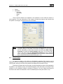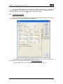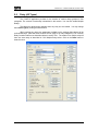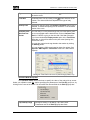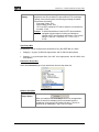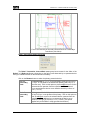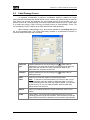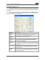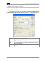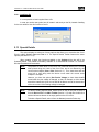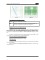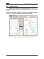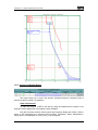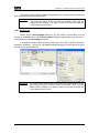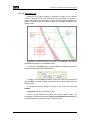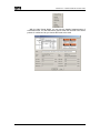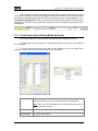
1
CYMTCC 5.0 Reference Manual and User Guide July 2009 © Copyright CYME International T&D Inc. All Rights Reserved No part of this publication may be reproduced, or transmitted in any form or by any means without the written permission of CYME International T&D. Possession or use of the CYME software described in this publication is authorized only pursuant to a valid written license agreement from CYME. CYME makes no warranty, either expressed or implied, including but not limited to any implied warranties of merchantability or fitness for a particular purpose, regarding these materials and makes such materials available solely on an "as-is" basis. CYME International T&D reserves the right to revise and improve its products as it sees fit. The information in this manual is subject to modification without notice. While every precaution has been taken in the preparation of this manual, CYME assumes no responsibility for errors or omissions, or for damages resulting from the use of the information contained herein. CYME International T&D Inc. 1485 Roberval, Suite 104 St. Bruno QC J3V 3P8 Canada Tel.: (450) 461-3655 Fax: (450) 461-0966 Canada & United States: Tel.:1-800-361-3627 Internet : http://www.cyme.com E-mail: [email protected] Other Trademarks: The names of all products and services other than CYME’s mentioned in this document are the trademarks or trade names of the respective owners. CYMTCC 5.0 – Reference Manual and User Guide Table of Contents Chapter 1 1.1 1.2 1.3 1.4 1.5 1.6 1.7 1.8 Chapter 2 2.1 2.2 2.3 2.4 Getting Started............................................................................................1 Overview of CYMTCC ..................................................................................1 Computer System Requirements .................................................................1 Running CYMTCC for Windows ...................................................................2 File Extensions .............................................................................................2 CYMTCC Graphic User Interface .................................................................3 Quick Reference ...........................................................................................5 1.6.1 CYMTCC Menus ..............................................................................5 1.6.2 CYMTCC Toolbars ...........................................................................5 1.6.3 Main Toolbar ....................................................................................6 1.6.4 Plot Toolbar ......................................................................................7 1.6.5 Diagram Toolbar...............................................................................8 1.6.6 Analysis Toolbar...............................................................................9 1.6.7 Drawing Toolbar .............................................................................10 1.6.8 Alignment Toolbar ..........................................................................11 1.6.9 Rotate Toolbar................................................................................11 1.6.10 Canvas Toolbar ..............................................................................12 1.6.11 Layout Toolbar ...............................................................................12 1.6.12 Special Details Toolbar ..................................................................13 1.6.13 Arc Flash Dist. Toolbar...................................................................13 1.6.14 Arc Flash Indu. Toolbar ..................................................................14 1.6.15 Database Toolbar...........................................................................14 1.6.16 Zoom/Pan Toolbar..........................................................................14 Mouse Commands......................................................................................15 1.7.1 Device Selection.............................................................................15 1.7.2 Pan and Zoom ................................................................................15 1.7.3 Information Tags ............................................................................16 1.7.4 Contextual Menus ..........................................................................17 1.7.5 Other Mouse Commands ...............................................................17 1.7.6 Message Window ...........................................................................18 Help Button in Dialog Boxes.......................................................................19 The One-Line Diagram .............................................................................21 One-Line Diagram Window ........................................................................21 2.1.1 OLD Workspace Elements.............................................................21 2.1.2 One-line Diagram Contextual Menu...............................................22 2.1.3 OLD Symbol Contextual Menu.......................................................24 Inserting and Connecting Symbols.............................................................25 2.2.1 Adding a Symbol ............................................................................25 2.2.2 Moving / Copying Symbols.............................................................25 2.2.3 Connecting Symbols ......................................................................25 Manipulating Components..........................................................................26 2.3.1 Selecting a Component ..................................................................26 2.3.2 Moving a Component .....................................................................27 2.3.3 Rotating / Flipping a Component....................................................28 2.3.4 Grouping and Ungrouping Components ........................................28 2.3.5 Ordering Components ....................................................................28 Drawing Capabilities ...................................................................................29 2.4.1 Drawing Lines and Shapes ............................................................29 2.4.2 Editing Vertices ..............................................................................32 CHAPTER 1 – GETTING STARTED 1 CYMTCC 5.0 – Reference Manual and User Guide Chapter 3 3.1 3.2 3.3 3.4 3.5 3.6 3.7 3.8 3.9 3.10 3.15 3.16 3.17 3.18 3.19 The File Menu............................................................................................33 Overview of the File Menu ..........................................................................33 New.............................................................................................................34 Open ...........................................................................................................34 Close...........................................................................................................34 Save............................................................................................................35 Save As.......................................................................................................35 Close All Studies.........................................................................................35 Open Workspace ........................................................................................35 Create Workspace ......................................................................................36 Preferences ................................................................................................36 3.10.1 Options ...........................................................................................36 3.10.2 Symbol Type...................................................................................40 3.10.3 Colors .............................................................................................41 3.10.4 Font for Grid and Font for Title Block .............................................42 3.10.5 Tags Customization........................................................................42 3.10.6 Keyword Format .............................................................................44 3.10.7 Default Line Properties...................................................................45 3.10.8 Diagram Measurements and Size..................................................45 3.10.9 Diagram Preferences .....................................................................46 3.10.10 Convert Study.................................................................................47 3.10.11 Direct Print......................................................................................47 Export Curve Plot to… ................................................................................48 Export All Opened Curve Plots...................................................................48 Print Diagram..............................................................................................48 3.13.1 Print ................................................................................................48 3.13.2 Print All Opened .............................................................................48 3.13.3 Print Preview ..................................................................................48 3.13.4 Print Setup......................................................................................49 Print Plot .....................................................................................................49 3.14.1 Print ................................................................................................49 3.14.2 Print All Opened .............................................................................49 3.14.3 Print Preview ..................................................................................49 3.14.4 Print Plot>Print Setup .....................................................................50 Print Setup ..................................................................................................50 Send............................................................................................................51 Properties ...................................................................................................51 List of Studies .............................................................................................52 Exit ..............................................................................................................52 Chapter 4 4.1 4.2 4.3 4.4 4.5 4.6 4.7 4.8 4.9 4.10 4.11 4.12 4.13 4.14 The Edit Menu ...........................................................................................53 Overview of the Edit Menu..........................................................................53 Undo ...........................................................................................................53 Redo ...........................................................................................................53 Cut ..............................................................................................................54 Copy............................................................................................................54 Paste...........................................................................................................54 Delete..........................................................................................................54 Select All .....................................................................................................54 Device Properties .......................................................................................55 Symbol Properties ......................................................................................55 Hidden.........................................................................................................57 Multi-Hide Selection....................................................................................57 Amps Multiplier ...........................................................................................58 Clipboard ....................................................................................................59 3.11 3.12 3.13 3.14 2 CHAPTER 1 – GETTING STARTED CYMTCC 5.0 – Reference Manual and User Guide 4.14.1 4.14.2 4.14.3 4.14.4 Chapter 5 5.1 5.2 5.3 5.4 5.5 5.6 5.7 5.8 5.9 5.10 5.11 5.12 5.13 5.14 Chapter 6 6.1 Paste to Plot ...................................................................................59 Copy Plot ........................................................................................59 Paste to Diagram............................................................................60 Copy Diagram ................................................................................60 The Create Menu.......................................................................................61 Device Creation ..........................................................................................61 Create Menu ...............................................................................................61 Common Window Elements and Commands.............................................62 5.3.1 Device Number...............................................................................63 5.3.2 Device ID ........................................................................................64 5.3.3 Device Voltage ...............................................................................65 5.3.4 Search ............................................................................................65 5.3.5 Param .............................................................................................66 5.3.6 Short Circuit & Full Load Amperes.................................................66 5.3.7 Location ..........................................................................................69 5.3.8 Coordination ...................................................................................69 5.3.9 Colors .............................................................................................71 5.3.10 Lib Editor ........................................................................................72 5.3.11 Symbol............................................................................................72 5.3.12 OLD Symbol ...................................................................................73 5.3.13 Edit Tag ..........................................................................................73 5.3.14 Add to Favorites…..........................................................................73 5.3.15 Apply...............................................................................................73 5.3.16 Draw ...............................................................................................73 5.3.17 Cancel ............................................................................................73 5.3.18 Information......................................................................................74 Fuse ............................................................................................................75 5.4.1 Vista Control ...................................................................................76 5.4.2 VFI Adjust .......................................................................................76 Recloser......................................................................................................77 5.5.1 Sequence .......................................................................................78 5.5.2 Electronic with TCC Setup .............................................................81 5.5.3 Electronic........................................................................................84 5.5.4 Single-Phase ..................................................................................86 5.5.5 Three-Phase Hydraulic...................................................................87 Relay (All Types) ........................................................................................88 5.6.1 Common Relay Creation Features.................................................89 5.6.2 Overtravel .......................................................................................98 5.6.3 Multiple Relay ...............................................................................100 Low Voltage Circuit Breakers (LVCB) ......................................................101 5.7.1 Electromechanical LVCB..............................................................102 5.7.2 Solid State LVCB..........................................................................103 5.7.3 Molded Case LVCB......................................................................105 5.7.4 Ground Fault LVCB ......................................................................106 Transformer ..............................................................................................107 Cable Damage Curves .............................................................................114 Motor Starting Curve.................................................................................115 Miscellaneous (User-defined)...................................................................116 Symbol ......................................................................................................118 5.12.1 Load from file................................................................................119 Special Details ..........................................................................................119 Special Details Toolbar.............................................................................122 The View Menu........................................................................................125 Introduction ...............................................................................................125 CHAPTER 1 – GETTING STARTED 3 CYMTCC 5.0 – Reference Manual and User Guide 6.2 6.3 6.4 6.5 6.6 6.7 6.8 6.9 6.10 6.11 Chapter 7 7.1 7.2 7.3 Customize Shortcuts.................................................................................125 Customize Toolbars..................................................................................126 Toolbar......................................................................................................127 Status Bar .................................................................................................127 Workbook..................................................................................................127 Multi Explorer............................................................................................128 Zoom.........................................................................................................128 Pan............................................................................................................128 One Line Diagram.....................................................................................129 Plot............................................................................................................130 6.11.1 Grid Options .................................................................................131 6.11.2 Layout Mode.................................................................................137 6.11.3 Other Plot Sub-Menu Options ......................................................137 The Mode Menu ......................................................................................139 Introduction ...............................................................................................139 Track .........................................................................................................139 Ruler .........................................................................................................139 Chapter 8 8.1 8.2 8.3 8.4 8.5 8.6 8.7 8.8 8.9 8.10 8.11 8.12 8.13 8.14 8.15 The Options Menu ..................................................................................141 Show Fault Arrow .....................................................................................141 Show Response Curve.............................................................................141 Show Response Curve Tag......................................................................141 Show Margin Anchor ................................................................................141 Display Device Number in Plot .................................................................141 Display Device Type in Plot......................................................................141 Display Device ID in plot...........................................................................142 Display Device Settings in plot .................................................................142 Display Device Number in OLD................................................................142 Display Device Type in OLD.....................................................................142 Display Device ID in OLD .........................................................................142 Display Device Settings in OLD................................................................142 Show Symbol Label ..................................................................................142 Show User Label ......................................................................................142 Title Block Information ..............................................................................143 8.15.1 Title Block Models ........................................................................144 8.16 Wheel Mouse Click ...................................................................................145 Chapter 9 9.1 9.2 9.3 9.4 9.5 9.6 9.7 The Reports Menu ..................................................................................147 Do Not Show Hidden Devices in Report ..................................................147 XML Format Reports ................................................................................147 9.2.1 Properties .....................................................................................148 9.2.2 Customize New ............................................................................149 9.2.3 Output examples ..........................................................................150 Summary (Tabular)...................................................................................152 Detail (Tabular) .........................................................................................154 View Custom Report.................................................................................154 Editor.........................................................................................................155 9.6.1 Report Editor ................................................................................156 View Custom Report.................................................................................156 Chapter 10 The Analysis Menu .................................................................................157 10.1 Protective Device Analysis .......................................................................157 10.1.1 Protective Device Loading Report................................................158 10.1.2 Protective Reach Report ..............................................................159 10.1.3 Interrupting Rating Report ............................................................160 10.1.4 Conductor Protection....................................................................161 4 CHAPTER 1 – GETTING STARTED CYMTCC 5.0 – Reference Manual and User Guide 10.2 10.3 10.4 10.5 10.6 10.7 10.8 10.1.5 Transformer Protection Report.....................................................162 10.1.6 Device Coordination Report .........................................................163 10.1.7 Device Coordination Options .......................................................165 Device Margin...........................................................................................166 10.2.1 Device Margin Modes...................................................................168 10.2.2 Display Options ............................................................................174 10.2.3 Margin Anchor ..............................................................................175 10.2.4 Draw Horizontal or Vertical Line between the Selected Devices.175 10.2.5 Draw Circle ...................................................................................176 10.2.6 Margin Report...............................................................................177 10.2.7 Device Description .......................................................................177 10.2.8 Other Useful Tips .........................................................................179 Margin Anchor ..........................................................................................179 Coordination Criteria.................................................................................181 10.4.1 Device Coordination Criteria – Window Elements .......................181 10.4.2 Device Coordination Criteria - Example .......................................185 Reach and Load Criteria...........................................................................186 Protection Criteria .....................................................................................187 Show Coordination Curves Based on Criteria..........................................188 Do Not Show Hidden Devices in Report ..................................................189 Chapter 11 The Arc Flash Analysis Menu................................................................191 11.1 Distribution Analysis .................................................................................191 11.1.1 NESC 2007...................................................................................191 11.1.2 Heat Transfer Model.....................................................................191 11.1.3 IEEE 1584-2002 Lee Method .......................................................192 11.1.4 Reports .........................................................................................192 11.2 Industrial Analysis.....................................................................................196 11.2.1 Standards .....................................................................................196 11.2.2 Data entry .....................................................................................196 11.2.3 Reports .........................................................................................197 11.2.4 Full Analysis .................................................................................200 11.2.5 View Existing Chart Report (CYMVIEW)......................................205 11.3 Arc Flash Parameters ...............................................................................206 11.3.1 General.........................................................................................206 11.3.2 Risk Category...............................................................................207 11.3.3 Protective Clothing Description ....................................................208 Chapter 12 12.1 12.2 12.3 12.4 12.5 12.6 12.7 The Tools Menu ......................................................................................209 Fast Adjust................................................................................................209 Clipping for all Curves...............................................................................209 Batch Modification in Opened studies ......................................................209 12.3.1 Coordination .................................................................................210 12.3.2 Colors ...........................................................................................211 12.3.3 Auto-Color ....................................................................................211 12.3.4 Short-Circuit .................................................................................212 12.3.5 Voltage .........................................................................................212 12.3.6 Tag ...............................................................................................213 12.3.7 Grid Options .................................................................................213 12.3.8 Recl. Sequence ............................................................................214 12.3.9 General Clipping...........................................................................214 12.3.10 Symbol Color ................................................................................215 Graphic Manager ......................................................................................215 Auto-Color List ..........................................................................................216 Backup Configuration Files (INI) Manager ...............................................217 Export Fuse Ranges .................................................................................218 CHAPTER 1 – GETTING STARTED 5 CYMTCC 5.0 – Reference Manual and User Guide 12.8 Export Settings to CYMDIST ....................................................................219 Chapter 13 13.1 13.2 13.3 The Database Menu................................................................................221 Overview of the Database Menu ..............................................................221 Change Library Database.........................................................................221 Library Editor ............................................................................................222 13.3.1 Views ............................................................................................225 13.4 Library On-line Update .............................................................................234 13.5 Import/Export ............................................................................................235 13.5.1 Overview.......................................................................................235 13.5.2 Export ...........................................................................................236 13.5.3 Export Modified Devices...............................................................236 13.5.4 Export Study Devices ...................................................................236 13.5.5 Export Studies Devices ................................................................236 13.5.6 Import ...........................................................................................236 13.6 Compact/Repair........................................................................................237 13.7 Convert (DBF to MDB)..............................................................................237 13.8 MDB Backup Manager .............................................................................238 13.9 Device Documentation Manager ..............................................................239 13.10 Settings Database Manager(TCS) ...........................................................240 Chapter 14 14.1 14.2 14.3 14.4 14.5 14.6 14.7 The Window Menu ..................................................................................241 Overview of the Window Menu.................................................................241 New Window.............................................................................................241 Cascade....................................................................................................241 Tile Horizontal...........................................................................................241 Tile Vertically ............................................................................................241 Arrange Icons ...........................................................................................241 Window List ..............................................................................................242 Chapter 15 The Help Menu ........................................................................................243 15.1 CYMTCC Contents ...................................................................................243 15.2 Readme.htm .............................................................................................243 15.3 What’s new (Part1 and Part2) ..................................................................243 15.4 Protection Key ..........................................................................................243 15.5 Check for Updates ....................................................................................244 15.6 Video Help ................................................................................................244 15.7 On-Line Help.............................................................................................244 15.8 Discussion Forum .....................................................................................245 15.9 CYME on the Web ....................................................................................245 15.10 About CYMTCC ........................................................................................245 Chapter 16 The Multi-Explorer ..................................................................................247 16.1 Overview ...................................................................................................247 16.1.1 Dock Windows..............................................................................248 16.1.2 Detach Tabs / Create New Multi-explorer Windows ....................249 16.1.3 Hide Tabs .....................................................................................250 16.2 Workspace Tab.........................................................................................250 16.2.1 Create Workspace........................................................................252 16.3 Settings Tab..............................................................................................253 16.3.1 Add a Device from an Existing Study...........................................257 16.4 Device Search Tab ...................................................................................259 16.5 Coordination Tab ......................................................................................261 16.6 Create Equipment Tab..............................................................................262 16.7 Favorites Tab............................................................................................263 16.7.1 Set up the Favorites .....................................................................263 16.8 Fast Adjust Tab.........................................................................................266 6 CHAPTER 1 – GETTING STARTED CYMTCC 5.0 – Reference Manual and User Guide Chapter 17 Library Editor Options ...........................................................................269 17.1 General Tab..............................................................................................269 17.1.1 Protective Type ............................................................................269 17.1.2 Characteristics..............................................................................270 17.2 Curve/Rating/Sensor Tab .........................................................................271 17.2.1 First Line.......................................................................................271 17.2.2 Curve Information.........................................................................271 17.2.3 Curve Data ...................................................................................272 17.3 Documentation Tab ..................................................................................276 17.4 Notes Field................................................................................................278 17.5 Warning Message.....................................................................................279 17.6 Time/Current Points Editor (Model as Points) ..........................................280 17.7 Model as Formula .....................................................................................281 17.8 Model as I2T .............................................................................................283 17.9 Range Editor.............................................................................................284 17.10 Curve Examples .......................................................................................285 17.10.1 Fuse..............................................................................................285 17.10.2 Relay Electromechanical..............................................................286 17.10.3 Relay Electronic ...........................................................................287 17.10.4 Motor Relay ..................................................................................288 17.10.5 Reclosers .....................................................................................289 17.10.6 LVCB Electromechanical..............................................................290 17.10.7 LVCB Static ..................................................................................291 17.10.8 LCVB Ground Fault ......................................................................292 17.10.9 LVCB Molded ...............................................................................293 17.10.10 Miscellaneous ........................................................................295 CHAPTER 1 – GETTING STARTED 7 CYMTCC 5.0 – Reference Manual and User Guide Chapter 1 1.1 Getting Started Overview of CYMTCC CYMTCC addresses coordination of protective devices in industrial, commercial and distribution power systems. • Use it to produce Time-current curve plots and device setting reports using any of the 15000 devices stored in the library. • If necessary, you can add new devices to the library, and edit the curves and setting ranges of the existing devices. • Plot curves on standard Keuffel & Esser log-log forms, or on plain paper. Export the one-line diagrams or the time-current curve plots to files for inclusion in reports. CYMTCC provides a CAD-like editor for the one-line diagrams. Click-and-drag device symbols from a menu onto the drawing surface (“canvas”), where you can move, rotate and connect the symbols. You can also draw parallel circuits. • Examine and change the settings of any device at any time. • Measure coordination margins on-screen using the mouse or the Device Margin function. • Ask CYMTCC to verify coordination automatically, according to your criteria. You have control over details such as current scale, plotting voltage, title block, curve colors, line thickness and device identification. • Customize the curve identification tags and move them around on the plot. • Insert special details such as company logos, title blocks and floating text balloons to enhance your drawings. The Coordination Wizard proposes settings for one or many protective devices of a given circuit. The proposed settings ensure that the protective devices are coordinated, i.e. that the device nearest to the fault will operate before its upstream device can function. 1.2 Computer System Requirements CYMTCC for Windows requires an IBM PC or compatible computer using Microsoft Windows 2000/XP/VISTA or later. The minimum hardware requirements are: • • • • • • An Intel Pentium or compatible processor. 512 MB of random access memory (RAM). 250 MB of hard disk space for the full version of CYMTCC. Mouse or other pointing device. Any printer or plotter supported by Windows. Screen resolution of 1024*768. CHAPTER 1 – GETTING STARTED 1 CYMTCC 5.0 – Reference Manual and User Guide 1.3 Running CYMTCC for Windows If you have a shortcut icon on your Windows desktop, double-click on it. Otherwise, CYMTCC is installed under Start > Programs > CYME > CYMTCC 5. Click on the CYMTCC icon. The usual procedure for performing a coordination study is to activate CYMTCC, open a new or existing study, and then either insert more devices (Create) or modify existing ones. You may open more than one study at a time. You may make copies of a study (File > Save As), and you may copy a device from one study to another (Edit > Copy). Make use of the Fast Adjust (Drag) mode to adjust the settings of devices by clicking and dragging the curves rather than editing them through the dialog boxes every time. Use the options under the Analysis menu when you want to check coordination margins or request a coordination verification according to your own criteria. When your work is done, save it via File > Save. Print it out via the File > Print command. View the device settings report via Tools > View Summary Report. Choose File > Exit to leave CYMTCC. 1.4 File Extensions The standard file extension for a CYMTCC study is “.TCC”. The .DAT extension identifies CYMTCC 3.x files – Users of CYMTCC 3.x can read their studies (“DAT” files) but if they save them, the files will be saved as “TCC files”. Users of the old CYMCOORD (DOS) program need to read and save their studies with CYMTCC 3.x before adopting CYMTCC 5. The .ETU extension identifies a study that had been created with the French version of the CYMTCC application, version 3.x. When a study with that extension is opened with an English version of CYMTCC, the data is displayed in English. Every time you open a study file (.TCC) a .BAK file with the same name is created in the same directory than its related .TCC file. So, if you need to go back to the same state the study was before you made your modifications, just rename the .BAK file to .TCC. Please note that if you reopen the study file (.TCC), you will not be able to go back to the previous state of the study. Remember that the .BAK file is created when the .TCC is open. The settings to protective equipment are stored as separate database files called Time Current Settings files (.TCS) in a database called the Database of Settings. This database is shared by CYMTCC and CYMDIST or PSAF. This database is sometimes called “Project Database”. Like a CYMTCC study, it will keep a link of the protective devices you entered in CYMDIST (or PSAF). It will also keep other information such as location and short-circuit values. You can define as many Databases of Settings as you want in CYMTCC. You can easily add a new Database of Settings from the CYMTCC using the Settings Tab of the Multi-Explorer (see 16.3). 2 CHAPTER 1 – GETTING STARTED CYMTCC 5.0 – Reference Manual and User Guide The CYMTCC.INI file comprises the various default parameters such as for visualization, precision, default information, etc. These defaults can be edited through various functions in CYMTCC. The equipment database, CYMTCC.MDB by default, contains all the time/current data points and other information related to each curve. (See Chapter 13 The Database Menu for more information.) The files with the extension .TCCWS contain the information related to the workspace. For more information see the Workspace Tab section 16.2. 1.5 CYMTCC Graphic User Interface The CYMTCC interface is basically composed of elements that will allow you accessing and displaying the data you want to work on, and using all the CYMTCC commands. When you open a study, the Curve Plot is shown in one window, and the associated One-line Diagram is displayed in another. Along the top of the screen is the Main Menu that provides all of the CYMTCC commands in pull-down menus. Immediately below that are the Toolbars, where icons provide instant access to frequently used menu commands. The various Toolbars are explained in the Quick Reference (Section 1.6). The Multi-Explorer pane appears to the left of the CYMTCC display. With it, you can access to the settings files (Settings Database), search devices, access the coordination options, access the create equipment option, and set-up a list of the devices you most often use. You will notice Tabs located at the bottom of the graphic displays. This the Workbook bar where all the study files currently opened are listed. The study names are indicated on the tabs. CHAPTER 1 – GETTING STARTED 3 CYMTCC 5.0 – Reference Manual and User Guide The Status Bar is located at the bottom of the window. The information that is displayed there depends on what you are doing. If you go to an option in the menu, for example, you will see in the Status Bar a description of the command that is selected. When you select a device, the Status Bar displays a description of that device. More explanation about the Curve Plot and The One-Line Diagram workspaces and about The Multi-Explorer pane are presented in Chapter 2 and Chapter 16 of this manual. 4 CHAPTER 1 – GETTING STARTED CYMTCC 5.0 – Reference Manual and User Guide 1.6 Quick Reference 1.6.1 CYMTCC Menus The MAIN MENU at the top of the CYMTCC screen gives access to all CYMTCC commands. The menu commands are enabled or disabled depending on whether there is an open study or not. Each menu item contains sub menu options. To display the sub menu click on the word in the menu with the left mouse button. Some sub-menu commands can be accessed by holding down the ALT key and the key corresponding to the letter underlined in the sub-menu item. You can assign or modify keyboard Customize Shortcuts to any of the menu commands. More about this can be found in section 6.2. 1.6.2 CYMTCC Toolbars The Toolbars contain icons, which give quick access to many menu commands. When you install CYMTCC without selecting the option of customizing the Toolbars, four will be installed by default: • Main Toolbar that includes icons for general commands such as file management, print, cut & paste, reports, zoom, pan, etc. • Plot Toolbar that includes commands used for the curve plots. • Diagram Toolbar that includes the most commonly used commands for the creation and editing of the one-line diagrams. • Analysis Toolbar that includes icons for accessing the dialog boxes used in defining the criteria of the analyses to run. CYMTCC comprises other Toolbars for more sophisticated diagram editing. To display those, customize your own, or hide a displayed toolbar, choose View > Customize > Customize Toolbars in the menu. (See section 6.3). The additional toolbars are: • • • • • • • • • • Drawing Toolbar Alignment Toolbar Rotate Toolbar Canvas Toolbar Layout Toolbar Special Details Toolbar Arc Flash Dist. Toolbar Arc Flash Indu. Toolbar Database Toolbar Zoom/Pan Toolbar CHAPTER 1 – GETTING STARTED 5 CYMTCC 5.0 – Reference Manual and User Guide Hint: You may rearrange the icons in the Toolbars. Press the “ALT” key and click and drag the icon to a new location. See also Section 6.3 Customize Toolbars. You may also move the Toolbars anywhere on the CYMTCC window. 1.6.3 Main Toolbar OPEN NEW STUDY. Opens a new study with the temporary name "Study1". Same as File > New. (Section 3.2) OPEN STUDY. Displays a list of available studies. Double-click on the one you want to open. If the screen already displays a study, new windows will open for the second study. Same as File > Open. (Section 3.3) SAVE STUDY. Updates the existing disk file or, if the study is a new one, creates a file with the name you specify. Same as File > Save. (Section 3.5). PRINT WINDOW. Opens the Direct Print Dialog Box allowing you to print the Plot and/or Onle line diagram. File > Print.... (see 3.13 Print Diagram). PRINT PREVIEW. A view that shows how the One-Line Diagram or the Plot will look like when you print them. OLD. Shows or hides the One-Line Diagram window. MULTI-EXPLORER. Shows or hides the Multi-Explorer pane. CUT. Removes the selected device and stores it in the CYMTCC clipboard. Same as Edit > Cut (Section 4.4) or the Shift-Delete key combination. COPY. Stores a copy of the selected device in the CYMTCC clipboard. Same as Edit > Copy (Section 4.5) or the Ctrl-Insert key combination. PASTE. Inserts a copy of the device in the CYMTCC clipboard into the one-line diagram, immediately upstream from the selected device. Same as Edit > Paste (Section 4.6) or the Shift-Insert key combination. MODIFY. Displays the Settings dialog box of the selected device. Same as Edit > Device Properties (Section 4.9) or the Shift-M key combination. Same as double-clicking anywhere in the plot or the one-line windows. Note: 6 CUT, COPY, PASTE and MODIFY require that you first select a device. (See Section 1.7.1 Device Selection) CHAPTER 1 – GETTING STARTED CYMTCC 5.0 – Reference Manual and User Guide PROPERTIES. Displays the Properties dialog box of the selected component. Same as Edit > Symbol Properties (See 4.10). UNDO. Cancels the last modification(s). Same as Edit > Undo. REDO. Repeats the last undone modification. Same as Edit > Redo. ZOOM / PAN. See Pan and Zoom (See 1.7.2 Pan and Zoom). RIGHT BUTTON MODE. See Pan and Zoom (See 1.7.2 Pan and Zoom). DEVICE LIST. Displays the selected device and allows selecting another device from the list of the devices in the active study. HIDE. Click here to hide the curve of the selected device. The device symbol remains in the one-line diagram. Useful if the curve plot is crowded. This button is highlighted when you hide a device curve, and each time you select a device which curve has been hidden. Same as the Shift-H key combination. Same as Edit > Hidden (Section 4.11) MULTI-HIDE. Opens the Multi-Hide dialog box. Lets you select the device curve(s) you would like to hide. The Protection column indicates if the device is used for phase or for ground protection if possible. XML REPORT. Displays the dialog box where you can select the reports you would like to see. Same as Tools > Summary (Tabular) (Section 9.3) Displays the Detailed Report. (See 9.4 Detail (Tabular)) 1.6.4 Plot Toolbar TRACK MODE. Puts the mouse pointer in Tracking mode. Displays the coordinates of the cursor position in the curve plot. Same as Mode > Track. (Section 7.2). RULER MODE. Calculates the distance (current and time) between any two points selected on the grid, and displays the results in the status bar. Same as Mode > Ruler. (Section 7.3). FAST ADJUST MODE (Drag Mode). To change the settings of a device by dragging its curve with the mouse. The Fast Adjust dialog box is available in the Multi-Explorer (see Chapter 16.8.) CHAPTER 1 – GETTING STARTED 7 CYMTCC 5.0 – Reference Manual and User Guide CURRENT SCALE. Multiplies the current scale by the chosen factor. See View > Plot (Section 6.11) PAGE LAYOUT. Shows the Curve Plot as it would appear if printed. See View > Plot (Section 6.11) GRID OPTIONS. See View > Plot (Section 6.11) DEVICE MARGIN. Detects curve intersections and measures time and current margins between curves. SECONDS / CYCLES. Displays time in cycles instead of seconds in the status bar. See View > Plot (Section 6.11) PLOTTING VOLTAGE. Selected voltage at which all time-current curves are plotted as if the devices were all in service at this voltage, to make it easy to compare the curves. See Options > Title Block Information (Section 8.15) Displays the Time (T:) and the Current (I:) mouse position in the plot. When in Ruler mode, the Delta values are displayed. Note: The same information is displayed in the status bar. 1.6.5 Diagram Toolbar The Diagram Toolbar comprises the main editing tools used for the creation and editing of the one-line diagrams. Please refer to Sections 1.6.7 through 1.6.11 for information on the additional drawing Toolbars. SELECT MODE. Normal selection mode. Changes the mouse pointer to an arrow to select one device at a time on the drawing. CONNECT MODE. Links and snaps a new symbol to an existing one. ORTHO. Links symbols with orthogonal vectors. GRID. Displays or hides the grid in the one-line diagram window. SNAP TO GRID. Snaps symbols to the drawing grid. PAGE BOUNDS. Displays the borders of the individual sheets on the canvas. FREE ROTATE. Allows rotating a component to any angle. 8 CHAPTER 1 – GETTING STARTED CYMTCC 5.0 – Reference Manual and User Guide ROTATE LEFT. ROTATE RIGHT. Rotates the selected symbol ninety degrees to the left or to the right, respectively. ALIGN TOP. ALIGN BOTTOM. Lines up multiple components to their top or their bottom edge, respectively. ALIGN MIDDLE. Centers multiple components horizontally. ALIGN LEFT. ALIGN RIGHT. Lines up multiple components to their left or their right edge, respectively. ALIGN CENTER. Centers multiple components vertically. 1.6.6 Analysis Toolbar RUN ANALYSIS. Verifies coordination, minimum clearing time and device loading level for all the devices of the current study. Same as Analysis > Protective Device Analysis. (section 10.1) MARGIN ANCHOR. Displays the Margin Anchor dialog box, from which you can set a line between two curves to calculate the gap between them. Analysis > Margin Anchor. (section 10.3) COORDINATION CRITERIA. Displays the Device Coordination Criteria dialog box, from which you may choose the criteria to verify coordination between devices. Same as Analysis > Coordination Criteria. (section 10.4) REACH AND LOAD CRITERIA. Displays the Protective Reach & Device Loading Criteria dialog box, from which you may choose the criteria to verify the clearing and loading of devices. Same as Analysis > Reach and Load Criteria. (section 10.5) PROTECTION CRITERIA. Displays the Device Protection Criteria dialog box, from which you may choose the criteria to verify the protection of transformers, cables and motors. Same as Analysis > Protection Criteria. (section 10.6) DISPLAY/HIDE CURVE. To display or hide the coordination curves on the plot view. Same as Analysis > Show Coordination Curves Based on Criteria > Display Curve (section 10.7) DISPLAY/HIDE HATCHING. To display or hide hatching between the device curve and the corresponding coordination curve. Same as Analysis > Show Coordination Curves Based on Criteria > Display Hatching (see section 10.7) CHAPTER 1 – GETTING STARTED 9 CYMTCC 5.0 – Reference Manual and User Guide 1.6.7 Drawing Toolbar Note: For the one-line diagram only. Section 2.4 Drawing Capabilities, provides details as to how to use these tools. SELECT. Normal selection mode. Changes the mouse pointer to an arrow to select one device at a time on the drawing. EDIT POINTS. Displays the vertices of a selected component so you can change the shape of that component. PROPERTIES. Displays the Component Properties dialog box for the selected symbol. (see section 4.10 Symbol Properties) LINE. To draw a straight line. POLYLINE. To draw a line with multiple angles. POLYGON. To draw a closed figure with three or more straight lines. RECTANGLE. To draw a rectangle or a square. POLYCURVE. To draw a line that curves smoothly at the inserted vertices. CLOSED CURVE. To draw a closed figure with two or more curves. ELLIPSE. To draw an ellipse or a circle. TEXT. To add new text or to edit existing text. IMAGE. To insert an existing .bmp or .dib image. 10 CHAPTER 1 – GETTING STARTED CYMTCC 5.0 – Reference Manual and User Guide 1.6.8 Alignment Toolbar Note: For the one-line diagram only. ALIGN TOP. ALIGN BOTTOM. Lines up multiple components to their top or their bottom edge, respectively. ALIGN MIDDLE. Centers multiple components horizontally. ALIGN LEFT. ALIGN RIGHT. Lines up multiple components to their left or their right edge, respectively. ALIGN CENTER. Centers multiple components vertically. NUDGE UP. NUDGE DOWN. Moves the selected component by one unit. With the SHIFT key pressed, moves by five units. NUDGE LEFT. NUDGE RIGHT. Moves the selected component by one unit. With the SHIFT key pressed, moves by five units. 1.6.9 Rotate Toolbar Note: For the one-line diagram only. FREE ROTATE. Allows rotating a component to any angle. ROTATE LEFT. Rotates the selected symbol ninety degrees to the left. ROTATE RIGHT. Rotates the selected symbol ninety degrees to the right. FLIP HORIZONTAL. Flips the selected component horizontally. FLIP VERTICAL. Flips the selected component vertically. CHAPTER 1 – GETTING STARTED 11 CYMTCC 5.0 – Reference Manual and User Guide 1.6.10 Canvas Toolbar Note: For the one-line diagram only. UNDO. Cancels the last modification(s). Same as Edit > Undo (Section 4.2). REDO. Repeats the last undone modification. Same as Edit > Redo (Section 4.3) GRID. Displays or hides the grid in the one-line diagram window. Same as View > One Line Diagram > Grid (section 6.10). SNAP TO GRID. Snaps symbols to the drawing grid. Same as View > One Line Diagram > Snap to Grid (section 6.10). ORTHO. Links symbols with orthogonal vectors. PAGE BOUNDS. Displays the borders of the individual sheets on the canvas. Same as View > One Line Diagram > Page Bounds (section 6.10). 1.6.11 Layout Toolbar Note: For the one-line diagram only. SPACE ACROSS. Evens the horizontal spaces between selected components. SPACE DOWN. Evens the vertical spaces between selected components. SAME WIDTH. Resizes the width of the symbols of selected components to the same width than the first symbol selected. SAME HEIGHT. Resizes the height of the symbols of selected components to the same height than the first symbol selected. SAME SIZE. Resizes the symbols of selected components to the same size than the first symbol selected. GROUP. Congregates two or more selected components into a single object. 12 CHAPTER 1 – GETTING STARTED CYMTCC 5.0 – Reference Manual and User Guide UNGROUP. Splits up the grouped components into individual components. BRING TO FRONT. SEND TO BACK. BRING FORWARD. SEND TO BACK. 1.6.12 Special Details Toolbar Note: For the time/current plot window only. ADD TEXT. To add a text label. Click on the icon and click on the plot to specify the location where you want to position the label. A Text Label dialog box will be displayed so you can enter your details. ADD CIRCLE. To add a circle on the plot. Click on the icon and click on the plot to specify the location where it will be displayed. ADD LINE. To add a line on the plot. Click on the Line button, and click on the plot with the left mouse button. The first click will indicate the X1,Y1 location. Hold down the mouse button, the mouse cursor will change to “Line”. Move the cursor to the desired X2,Y2 location and release the mouse button. 1.6.13 Arc Flash Dist. Toolbar Displays the NESC 2007 report. (See 11.1.1) Displays the Heat Transfer Model report. (See 11.1.2) Displays the Lee Method report. (See 11.1.3 IEEE 1584-2002 Lee Method) Opens the Arc Flash Parameters dialog box. (See 11.3) CHAPTER 1 – GETTING STARTED 13 CYMTCC 5.0 – Reference Manual and User Guide 1.6.14 Arc Flash Indu. Toolbar Displays the IEEE 1584 report. (See section 11.2 Industrial Analysis) Displays the NFPA report. (See 11.2 Industrial Analysis) Opens CYMVIEW. (See 11.2.5 View Existing Chart Report (CYMVIEW)) Opens the Arc Flash Parameters dialog box. (See 11.3) 1.6.15 Database Toolbar Opens the Change Library Database dialog box. Use it to set the path of your library MDB file. (See 13.2) Opens the Library Editor dialog box. (See 13.3) Opens the Library On-line Update dialog box. Use it to get the new curves available on our website. (See 13.4) Opens the Database Export dialog box. (See 13.5.2 Export) Opens the Database Import dialog box. (See 13.5.6 Import) 1.6.16 Zoom/Pan Toolbar See 1.7.2 Pan and Zoom, for all the details. 14 CHAPTER 1 – GETTING STARTED CYMTCC 5.0 – Reference Manual and User Guide 1.7 Mouse Commands 1.7.1 Device Selection You will need to “select” devices to perform a number of actions. There are four ways to select a device: 1. In the One-line Diagram workspace: Left-click once on the symbol. 2. In the Curve Plot workspace: With the cursor in Track Mode (see Section 7.2), leftclick once on the curve or the tag of the device. 3. In the Multi-Explorer pane, click on the Coordination Tab to see the list of devices, left-click once on the name of the device. 4. On the Main Toolbar Device combo box: Click on the (Ð) symbol to display the device list. Then click on the device name in the list to select it. When a device is selected: • its set-up data is displayed in the Status Bar, at the bottom of the CYMTCC application window. • its symbol is highlighted on the one-line diagram (when displayed). • its name appears in the Device list box in the Main Toolbar. You can select more than one device on your one-line diagram. In the One-Line Diagram workspace, left-click once on a symbol. To select the next devices, press the SHIFT key and leftclick once on the other symbols wanted while keeping the SHIFT key down. 1.7.2 Pan and Zoom There are two ways to pan: 1. Click once in the workspace (one-line or plot) to activate it. Click the Pan button in the Main Toolbar or in the Zoom/Pan Toolbar. Click the left mouse button once anywhere in the One Line Diagram workspace or the Plot workspace and hold the button down. Move the mouse to reposition the cursor and release the button of the mouse. 2. Click the right button hold it down and drag the mouse. Release the button. Note: For the One Line Diagram, you have to click the RIGHT BUTTON MODE icon in the Main Toolbar or in the Zoom/Pan Toolbar in order to use the right mouse button. The drawing will move the same distance in the same direction, as though you had pulled it with the mouse. CHAPTER 1 – GETTING STARTED 15 CYMTCC 5.0 – Reference Manual and User Guide You can zoom in your one-line diagram or your plot curves to get a close-up view of a selected area. There are two ways to do this: in the Main Toolbar. Then click the left button of 1. Click once on the Zoom icon the mouse pointing to a corner of the area you wish to zoom in. Keep the mouse button down and drag a rectangle over the area to zoom. Release the mouse button. 2. Point in the drawing to a corner of the area you wish to zoom in and press twice on the right button of the mouse. On the second click, hold the button down and drag a rectangle over the area to zoom. Release the mouse button. Note: For the One Line Diagram, you have to click the RIGHT BUTTON MODE icon in order to use the right mouse button. You can zoom in and out by increments. First, click once anywhere on the workspace or Zoom Out (one-line or plot) you wish to zoom, to activate it. Click on the Zoom In buttons in the Main Toolbar or in the Zoom/Pan Toolbar. Each time you will click on these buttons, your drawing will zoom in or out, by increments. It will work the same way whether you are in Right Button Mode or not. Finally, you can zoom in your workspace to the size of your drawing. Click once on the . The drawing will be fit workspace you wish to zoom. Click on the Zoom To Fit button once to the size of your workspace. It will work the same way whether you are in Right Button Mode or not. Note: 1.7.3 For the one line diagram, when the “Right-Button” icon is active, you have the ability to Pan and Zoom at all times, but you sacrifice access to the menus you otherwise obtain when you right-click. Information Tags When you move your mouse over the symbols on the one-line diagram or the curves in the plot, information tags will be displayed for each equipment. This will help you identify more easily the equipment in your drawings. 16 CHAPTER 1 – GETTING STARTED CYMTCC 5.0 – Reference Manual and User Guide 1.7.4 Contextual Menus You have access to a Contextual Menu when you right-click on symbols in the One-Line Diagram display, or in the background One-Line Diagram window. In the Plot window, several different contextual menus will be display. If the click was done on a tag, a curve, a graphic or in the background, the menu list will be different. Also, depending on the type of curve you have clicked on, the menu will display options related to this curve type. Notes: When the “Right-Button” icon is active, you cannot access to the contextual menus, in the one line diagram, by right-clicking on the symbols. If you put your mouse cursor on a curve, a tooltip will appear showing the curve name and its curve type. 1.7.5 Other Mouse Commands You will use your mouse for other types of actions in CYMTCC. See the following Sections for all details: • Inserting and Connecting Symbols (section 2.2) • Manipulating Components (section 2.3) CHAPTER 1 – GETTING STARTED 17 CYMTCC 5.0 – Reference Manual and User Guide 1.7.6 Message Window Located at the bottom of the CYMTCC screen, a message window will appear if you are opening a study containing a device that is not in the database or if a device contains a warning message. The window will also appear when the Draw button of the device dialog is press and that the selected device contains a warning message. This window will also show you different error messages, warnings or suggestions. Column 1 Row Number. 2 Type of Message. (Warning or Error) 3 Device Name. Click on the device name to open the Device Properties dialog box. 4 Name of the study. 5 Do not Show again. If you don’t want to see this message again, click the button. 1.7.6.1 Add a warning to a device type From the Device Properties dialog box, select the type you would like to add a warning on and click the Lib. Editor Button. The library editor will open; add a message in the warning field. Click the the warning field then click the … button to enter you message. (See Warning Message in chapter 17.5) 18 CHAPTER 1 – GETTING STARTED CYMTCC 5.0 – Reference Manual and User Guide 1.8 Help Button in Dialog Boxes If you need help about a specific dialog box, click the question mark icon located at the top right corner of the dialog box. CHAPTER 1 – GETTING STARTED 19 CYMTCC 5.0 – Reference Manual and User Guide Chapter 2 2.1 The One-Line Diagram One-Line Diagram Window The One-Line Diagram (OLD) Window is the workspace where the user will create and edit the one-line diagrams. 2.1.1 OLD Workspace Elements Canvas CYMTCC provides a drawing surface abstraction, also known as the canvas, onto which you can draw and manipulate symbols and graphics. Each canvas has a grid that can be shown behind the diagram. You can use the grid to align graphical components. Objects on the canvas encapsulate graphical elements that can be moved, rotated and connected. CYMTCC comes with predefined symbols that you can drag and drop into drawings, connecting and positioning them precisely to create your schematics. CYMTCC also provides a set of tools, such as lines, arcs, polylines, rectangles and circles, for drawing additional elements. Component A component is an object drawn onto the canvas. Device symbols and drawing entities (such as lines, text, ellipses, and rectangles) are examples of components. Components have a logical position and occupy a rectangular area on the canvas. Components can be assigned properties such as fill color, line color and font that determine their appearance. Symbol Each symbol has its own unique functionality and characteristics specific to the one-line diagram. Symbols are designed to be moved or connected in logical ways only. For example, when you drag the symbol “fuse” onto a canvas and drag it close to a target symbol, the fuse aligns correctly to connect with the target symbol. Symbols are designed to behave in specific ways suited to the one-line diagram they are intended for. Properties “Properties” provide a flexible and dynamic way of associating fonts, line style, colors, or other features to a component. Each symbol is defined by properties, some of which you can change to modify or format the symbol. To view or change the symbol’s properties, select the symbol on the canvas and right-click. Select Symbol Properties on the menu. Each time you drag a symbol from the symbol window to a drawing, you create a copy of the symbol that looks similar to the parent symbol. Control Handles Control handles (or anchors) are small boxes that appear on a symbol when you select it. A symbol always has eight control handles that define a box enclosing the symbol. CHAPTER 2 – THE ONE LINE DIAGRAM 21 CYMTCC 5.0 – Reference Manual and User Guide Links and Ports Links are lines or polylines that connect two symbols by snapping to ports. A port defines a location on a symbol at which other symbols can be connected. A link binds together two ports. Symbols have normally a port on either endpoint. Once you connect two symbols with a link, they remain connected when you move either symbol. The link changes shape and size to accommodate the move. Link uses the current line format. For example, if you want connectors to have a different color, change these properties in the Property dialog box when nothing in the one-line diagram is selected. See 2.2.3 Connecting Symbols. Labels Labels are text components that you can use to annotate a symbol. There are two of those labels: the Symbol Label (see 5.3.11 Symbol) and the Symbol User Label (see 2.1.2 Oneline Diagram Contextual Menu, below) 2.1.2 One-line Diagram Contextual Menu Right-clicking in the background of the One-Line Diagram window will display a contextual menu that provides page management options to make quick changes. This contextual menu concatenates commands you can access through the View > One Line Diagram menu item, and a quick zoom option. Complete Default Properties can also be accessed through File > Properties menu commands. (See section 3.10 Preferences for details). The commands include: 22 Page Bounds To display or hide the page boundaries of large drawings. Grid To display or hide the grid. Snap to Grid To align to the grid the top left handles of each component in your diagram. Angle Snap To limit the rotation of objects to fifteen-degree increments. CHAPTER 2 – THE ONE LINE DIAGRAM CYMTCC 5.0 – Reference Manual and User Guide Grid Properties To display the Grid Properties dialog box to change the distance between the points of the grid or to change the color of the grid. Zoom Provides an extra way to quickly zoom on your one-line diagram. As follows: Default Properties To define the overall properties of the components in the drawing. Note, however, that this will apply to the next components you will add to your one-line diagram. The properties that can be set are: Line, Fill and Font, refer to section 3.10 Preferences for more details. Note: If you want to change the properties of a component that is already in your drawing, left-click on that object and right-click to access its contextual menu, or through the corresponding Edit > Symbol Properties menu item. CHAPTER 2 – THE ONE LINE DIAGRAM 23 CYMTCC 5.0 – Reference Manual and User Guide 2.1.3 OLD Symbol Contextual Menu Selecting a symbol on the OLD and right-clicking on it will display a contextual menu that provides quick access to a number of commands to make changes to that symbol. The Label ID commands allow to show or hide the Label ID (symbol identification elements), the Symbol Label (entered through the Symbol command of the Device Settings dialog box (see section 5.3.11), or the User Label which is an extra function to describe your device. (see below) The Symbol User Label is a text component that you can use to annotate a symbol. Select the symbol and right click on it to get the menu for adding text via the command User Label. The Symbol Properties (section 4.10) and the equipment properties (see section 5.1 Device Creation) commands will display the corresponding dialog boxes. 24 CHAPTER 2 – THE ONE LINE DIAGRAM CYMTCC 5.0 – Reference Manual and User Guide 2.2 Inserting and Connecting Symbols 2.2.1 Adding a Symbol There are three ways to insert a symbol into your one-line diagram: 2.2.2 • Drag and Drop – Click a symbol in the Device Search, Create Equipment Favorite or Settings window of The Multi-Explorer (see Chapter 16), then drag the symbol over the canvas and drop it. • Double click on a symbol in the Device Search, Create Equipment, Favorite, Settings window of the multi-Explorer. • Select an equipment from the Create Menu. (Section 5.2) Moving / Copying Symbols You can do this two ways: 2.2.3 • Select the symbol and drag it to a new location. To keep a copy at the original location, hold down the CTRL key while dragging. • Select the symbol and right-click on it to select Copy or Cut from the menu. To paste, right click where you would like the symbol to be on the canvas, and select Paste from the menu. Connecting Symbols CYMTCC provides two methods to allow the user to connect two symbols on the one-line diagram: Link command method: 1. To connect two symbols, click on the Connect button located in the Diagram Toolbar (see 1.6.5) to activate the Connection mode. 2. Position your mouse over the first device until the mouse pointer changes to a red circle. When it does, click on the left button of the mouse and hold it down, the mouse pointer will change to a plus sign. 3. Still holding the button down, move your mouse to the second device to connect until the mouse pointer changes again to a red circle, click twice on the left mouse button to connect the two devices. CHAPTER 2 – THE ONE LINE DIAGRAM 25 CYMTCC 5.0 – Reference Manual and User Guide Drag-and–drop method: 1. Go to the Create Equipment Tab of the Multi-Explorer pane (see 16.6). Select your symbol by clicking on its name in the list with the left mouse button and hold the button down while you drag the symbol over the OLD workspace. 2. When the symbol approaches a target symbol, a mouse tooltip is displayed. 3. Allow the symbol to snap to the target symbol. Release the mouse button. 4. The Settings dialog box of the new device will be displayed. Complete it, and click the Draw button: the two symbols are connected. 2.3 Manipulating Components CYMTCC provides you with a range of actions that you can perform on the symbols. Before you can enable the actions, you must have the appropriate toolbar available. You must also be located on the One-Line Diagram workspace rather than on the Plot workspace. Left-click once on the One-Line Diagram window to activate it. To make the toolbars available, go to the View > Customize menu item. You will get a list of toolbars. Click on the ones you need. (see section 1.6.2 CYMTCC Toolbars) Once the toolbars are in place, you can easily enable: • • • • • • Selection Movement Rotation Scaling Alignment Cut, Copy, and Paste You can also perform these advanced actions: • • • • 2.3.1 Grouping/Ungrouping Stacking Order (Z-Order) Grid Alignment Defining relationships between symbols Selecting a Component By default, the application starts in Selection Mode. If you are not in Selection Mode, you can switch to it by clicking the Selection tool button . See 1.7.1 Device Selection about the various ways available to select a symbol. When a device is selected: • • • 26 its set-up data is displayed in the Status Bar, at the bottom of the CYMTCC application window. its symbol is highlighted on the one-line diagram (when displayed). its name appears in the Device List box in the Main Toolbar. CHAPTER 2 – THE ONE LINE DIAGRAM CYMTCC 5.0 – Reference Manual and User Guide You can select a single component by clicking it while the Selection Mode is activated. If you want to select multiple components, hold the CTRL key and then click each of the components you want to include in the selection, or click and drag in an empty space to draw a selection rectangle. The last component selected for a multiple selection is distinguished from the others by its grey selection handles. The grey handles are used to indicate that it is an anchor component. The editor uses anchor components as a reference for alignment operations. If you want another component to serve as the anchor, hold the CTRL key and then click on another component within the selection. The editor transfers the grey handles from the previous component to the selected component. To deselect a single component from a group, press the SHIFT key and click the component you want to exclude from the selection. 2.3.2 Moving a Component , you can move certain components by clicking them and When in Selection Mode dragging the mouse. When you place the pointer over a component that you can move, the If the Snap to Grid option in the canvas is mouse pointer changes to a “can move” pointer. enabled, the top left corner of the component’s bounding box aligns with the grid. You can easily line up multiple components using the alignment operations. The anchor component in a multiple selection, which is distinguished by its grey selection handles, is the point of reference to which all other components in the multiple selection align. You can align objects horizontally (top, center, bottom) or vertically (left, middle, right). You can slightly move the selected components using the “nudge” operations. These commands move the components by one unit by default and by five units if you are holding the SHIFT key. You can nudge an object up, down, left or right. CHAPTER 2 – THE ONE LINE DIAGRAM 27 CYMTCC 5.0 – Reference Manual and User Guide 2.3.3 Rotating / Flipping a Component To rotate the selected component to any angle, click the Rotate tool button . Now when you place the cursor over a component that can be rotated, the mouse pointer's shape . Click the component you want to rotate or one of the components in a changes to reflect this multiple selection and then drag the mouse to rotate the component in place. If you hold the SHIFT key while rotating, the rotation snaps to fifteen-degree increments. The same effect occurs automatically if you select the Angle Snap option in the canvas (right-click menu or the menu option View > One Line Diagram > Angle Snap). You can also rotate the component by ninetydegree increments using the Flip Left or the Flip Right toolbar commands; and also flip the component vertically or horizontally. 2.3.4 Grouping and Ungrouping Components You can group components together to form composites using the Group button . Select the components you want to group together by forming a rectangle around them and then clicking the Group button. Grouped components act like a single graphical component. Any change you make to a composite affects each of its components. Because a composite is also considered a component, you can create a composite that is composed of other composites. To ungroup a composite object, select the composite you want to ungroup and then click the Ungroup button 2.3.5 . Ordering Components The individual components in a diagram understand the concept of a stacking order, also known as z-order. Stacking order determines where each component is drawn in the stack. In other words, the order determines which component is drawn last. The last drawn component is shown over the components already on the canvas. Z-order is determined by the order in which the components are added to the diagram. The last component to be added will be on top. You can change the default order with the order commands. You can change the order of the components by moving a component either one place forward or backward, or by sending a component to the front or back of the stack. 28 CHAPTER 2 – THE ONE LINE DIAGRAM CYMTCC 5.0 – Reference Manual and User Guide 2.4 Drawing Capabilities CYMTCC contains the same graphic primitives available in most drawing applications: • Line • Polygon • Rectangle • Curve • Closed curve • Ellipse • Text • Image (bitmap) In CYMTCC, you insert a symbol into the canvas by selecting a tool button in the Drawing Toolbar (see 1.6.7), placing the pointer in the canvas, and then clicking the left mouse button. In addition to providing this functionality, CYMTCC also enables you to draw primitive components using the methods described below. You can assign line properties (color, width) to each graphical component, and fill properties to the closed shapes (rectangle, closed curve, etc.) 2.4.1 Drawing Lines and Shapes To Draw: You will: A component of equal proportions or at a 90 degrees angle. Hold the SHIFT key while drawing a component. For example, if you select the Rectangle tool button and then click in the canvas while holding the SHIFT key, the application will draw a square. A component centered on a point. Hold the CTRL key while drawing a component. A line A polyline CHAPTER 2 – THE ONE LINE DIAGRAM Click the Line button and then click and hold the mouse button in the canvas until the line is of the appropriate length. Click the Polyline button and then left-click on the canvas to place the first vertex. Release the mouse button and move the cursor to the location of the next vertex. Click again to place a vertex. Double-click to place the last vertex and finish the polyline. Click the right mouse button to cancel the action (before placing the last vertex). 29 CYMTCC 5.0 – Reference Manual and User Guide To Draw: A polygon A rectangle or a square A polycurve You will: and then left-click on the canvas Click the Polygon button to place the first vertex. Release the mouse button and move the cursor to the location of the next vertex. Click again to place a vertex, and so on. Double-click to place the last vertex and finish the drawing. Click the right mouse button to cancel the action (before placing the last vertex). and then click and hold the Click the Rectangle button mouse button in the canvas, positioning the pointer to a corner of the rectangle or the square you wish to draw. Drag the pointer until the rectangle is the width and length you want. (Press SHIFT to draw a square.) and then click in the canvas to Click the Polycurve button place the first vertex. Release the mouse button and move the cursor to the location of the next vertex. Click again to place a vertex, and so on. As you place the vertices, CYMTCC displays a dotted line that shows the shape of the finished line. Double-click to place the last vertex and finish the drawing. Click the right mouse button to cancel (before placing the last vertex). A closed curve Click the Closed Curve button and then click in the canvas to place the first vertex. Release the mouse button and move the cursor to the location of the next vertex. Click again to place a vertex, and so on. As you place the vertices, CYMTCC displays a dotted line that shows the shape of the finished line. Double-click to place the last vertex and finish the drawing. If you do not place the last vertex at the same position than the first one, CYMTCC will do that automatically. Click the right mouse button to cancel (before placing the last vertex). 30 CHAPTER 2 – THE ONE LINE DIAGRAM CYMTCC 5.0 – Reference Manual and User Guide To Draw: An ellipse or a circle To add text To insert an image CHAPTER 2 – THE ONE LINE DIAGRAM You will: and then click and hold the Click the Ellipse button mouse button in the canvas until the ellipse or the circle has the shape and the size you want. (Press SHIFT to draw a circle.) Click the Text button and then click in the canvas to position the box. Right-click on that box to access the Component Properties dialog box and type your text the Text field. Click OK when done. You can modify your text or adjust the text properties by right-clicking on the text component to access again the Component Properties dialog box. Click the Image button to open a standard Open dialog box from which you select an image in either .bmp or .dib format. Click OK, and then left-click once on the canvas at the position where you want the image to be inserted. 31 CYMTCC 5.0 – Reference Manual and User Guide 2.4.2 Editing Vertices When you select a primitive component such as a line or a rectangle, the editor places control handles at each vertex defining the shape. You can manipulate these vertices to change the shape of a component. However, these commands do not apply to all components. For example, if you had a line component with only two vertices, you would not be able to delete a vertex. Moving a Vertex – To move a vertex, position the mouse over a control handle. The cursor changes to signal that you can move this vertex. Click the control handle and keep the mouse button pressed while dragging the vertex to a new position. Release the mouse button to place the vertex at its new coordinates. Inserting a Vertex – To insert a vertex, move the mouse between two control points and hold down the CTRL key. The cursor changes to signal that you can insert a vertex. Click the mouse button to place the vertex on the line segment. Removing a Vertex – To remove a vertex, move the mouse over a vertex and hold down the CTRL key. The cursor changes to signal that you can delete the vertex. Click the mouse button to delete the vertex from the component. 32 CHAPTER 2 – THE ONE LINE DIAGRAM CYMTCC 5.0 – Reference Manual and User Guide Chapter 3 3.1 The File Menu Overview of the File Menu When you start working with CYMTCC, you will either create a new study or work on an existing one. A study consists of the following: 1. A Time-Current Curve Plot, 2. A One-line diagram, Studies may be opened, saved and printed by using the commands in the File menu. Commands may be activated by selecting them from the menu or, in some cases, by clicking on an icon. Several studies may be opened simultaneously. You may move from one to another by clicking in the window of the desired one, to make it the active window. The File Menu The Preferences sub menu The Export All opened Curve Plot to sub menu The Print Diagram and Plot sub menu CHAPTER 3 – THE FILE MENU 33 CYMTCC 5.0 – Reference Manual and User Guide 3.2 New This file command opens a new blank study. By default, CYMTCC opens the new study under the name "Study1.TCC". (if you open another new study, the name will be “Study2.TCC”, and so on). A window opens with one pane for the One Line diagram and another pane for the Curve Plot. All opened windows are automatically tiled. You may change the study name by using File > Save. 3.3 Open This command opens an existing study. A standard Windows Open dialog box appears, through which you can navigate through your directories and select the file to open. You may list all files in any directory and drive. The study file extension is .tcc Select one by any of these three methods: 1. Double-click on its name. 2. Click once on its name and click on the Open button. 3. Type its full name and path, and click on the Open button. 4. Select more than one file (with the mouse or by holding down the Shift or CTRL button on your keyboard) and click the Open button. 5. Double clicking on the file name. 6. Drag and drop one or more studies on the CYMTCC desktop icon or on the Cymtcc.exe file. A window opens with one pane for the One Line diagram and another pane for the Curve Plot. All open windows are automatically tiled. 3.4 Close This command closes the active study file. If you have modified the study since you last saved it, CYMTCC will ask you whether you want to save the study. If you close without saving, you lose any modifications made since the study was last saved. Clicking on the X icon at the top right corner of the window has the same effect. 34 CHAPTER 3 – THE FILE MENU CYMTCC 5.0 – Reference Manual and User Guide 3.5 Save Saves the active study under its file name. If the study is a new one, CYMTCC performs the Save As... command instead. Note: Old CYMTCC “DAT” files will be saved as “TCC” files. The old file is not changed. It is recommended that you Save regularly to reduce the risk of data loss in case of power failure. It is good practice to save the current study before opening another one. Note: You can use the Auto-Save Manager available in the Tools menu to enable the auto save and/or the auto recovery option. (See chapter 3.10.1.2). Also, CYMTCC creates a backup copy of your file for you. If the study to be saved already exists, the existing file is renamed with the ".BAK" extension before the Save is carried out. You can open the “BAK” file. 3.6 Save As Prompts for the name of a file in which to save the study, and then saves it there. This command is useful for making studies, which are very similar to others. You may type in the path and the name of your file in the File Name box and click on the Save button. You may also select a drive and directory, then type in or select a file name, and click Save. 3.7 Close All Studies This command closes all opened studies. If you have modified any studies since you last saved them, CYMTCC will ask you whether you want to save each one. If you close without saving, you lose any modifications made since the studies were last saved. 3.8 Open Workspace Allows you to open an existing workspace saved on your computer. This command is also available by right clicking on the workspace area located in the Multi-Explorer. (For more information see 16.2 Workspace Tab) CHAPTER 3 – THE FILE MENU 35 CYMTCC 5.0 – Reference Manual and User Guide 3.9 Create Workspace This command will open the Create Workspace dialog box. (For more information see 16.2 Workspace Tab) 3.10 Preferences 3.10.1 Options This menu command displays the following dialog box, which you use to define overall parameters. These settings are persistent, meaning that they will be used for all subsequent CYMTCC sessions. 3.10.1.1 System Tab 36 Plotting voltage When you open the program or a new study, this default value will be set as your study voltage. The new value becomes the new default. User name used by CYMTCC CYMTCC is saving the users name when a study file is saved (See 3.17 Properties) or when a modification is done in the library (See Library Editor in section 13.3). CHAPTER 3 – THE FILE MENU CYMTCC 5.0 – Reference Manual and User Guide Language You have the possibility to select from three different languages: English, French and Spanish. The default selection is based on the selection made during the software installation. To change the language, make your selection, click the Save button and restart CYMTCC. A number of different options are based on language; including the following. • CYMTCCRes.dll: Interface and messages • Readme.htm • Online Help • Arc Flash labels Tip info on curve When you move the mouse over a curve in the plot, a mouse tooltip is displayed. With this option, you can select if the tooltip will display the time-current position (Display x,y coordinate) or the equipment information (Display tag). Note: The time-current position is also displayed in the Status Bar regardless of the type of tooltip selected. Recent Files The Recent Files list is located at the bottom of the file menu. It shows the last six studies that were opened. You can select to display the files by study name (File Name) or by study name with full path (Full Path) Ini File check at startup At program startup, CYMTCC will verify if your Cymtcc.ini file is read-only. If this is the case, a warning message will let you know If you continue working with the Cymtcc.ini in read-only, your settings/ parameters, such as default curves color, default grid type and many more, will not be saved and you will have to select those settings every time a new study is created. Configuration File Path: Cymtcc.ini To select another location for your INI files. This is in case the user does not have the rights to modify files located in the Windows folder. In order to make this modification, you have to login with an account that as the rights to modify the registry. Once the modification is done, the user can login with its regular account and use the software knowing that all its settings will be saved. CHAPTER 3 – THE FILE MENU 37 CYMTCC 5.0 – Reference Manual and User Guide Configuration File Path: XML report Style sheet folder When the XML reports are generated, files are created, by default, in the CYME\CYMTCC\StyleSheet folder (See XML Format in section 9.2). If the user does not have the rights to modify or create files located in this folder, the report cannot be generated. This is why it might be necessary to modify the location of these files. In order to make this modification, you have to have the rights to modify the Cymtcc.ini file. 3.10.1.2 Auto-Save Manager Tab This option gives you the possibility to automatically save at a regular intervals all your opened studies that have been modified. Also, you can create a recovery file in case the program did not close normally. 38 1. Activate the Save Study Every … • Check the Save Study Every checkbox. • Enter a value in minutes. 2. Activate the Auto Recover • Check the Save Auto Recover checkbox. • Enter a value in minutes. • Specify the folder where you want your auto-recover file to be saved in. It is important to use a folder that you can create files in. Usually, the “temp” folder will work. If it is not the case, select the Create in other directory option and click the Browse button to select the folder. CHAPTER 3 – THE FILE MENU CYMTCC 5.0 – Reference Manual and User Guide How the Auto-Recover works • At the interval indicated, a copy of your opened studies will be saved in the specified folder. • If the program exits normally (i.e. closed by the user), the studies file located in the recovery folder will be deleted. • If the program does not close normally (power failure or crash), when you restart CYMTCC, you will have the possibility to reopen those studies. Note: A folder named Cymtcc_rec will be created under the selected recovery folder. 3.10.1.3 Error Manager Tab (More to come) CHAPTER 3 – THE FILE MENU 39 CYMTCC 5.0 – Reference Manual and User Guide 3.10.2 Symbol Type Displays the Symbol Type dialog box, with which you can assign a symbol to the each equipment type. 1. Select an equipment type from the list by clicking on its name. This will display the available symbols in the right part of the dialog box. 2. To select the desired symbol, click on the radio button underneath the symbol you want. Note: 40 The change will only apply to the next devices created. CHAPTER 3 – THE FILE MENU CYMTCC 5.0 – Reference Manual and User Guide 3.10.3 Colors This option applies to the colors of the curves of the devices displayed in the Plot workspace. It is also possible to set a specific color to each symbol. With the Colors dialog box, you can assign color, hatching, line type and line thickness to the curve of each type of equipment. You may also change the colors of the grid lines and the background (respectively “Grid” and “Background” in the Items list). You also have the possibility to change the one line diagram symbol color. 1. Select one or more item from the list by clicking on its name. Hold down the CTRL key on your keyboard to do a multiple selection. Notes: • If you have selected more than one item, check the settings you would like to change. • Use the Filter to list items specific to the selected device or curve type. 2. Select the Hatch and Line type you want by clicking on the appropriate choices. 3. Adjust the Line Width by clicking on the up and down arrows. 4. Click on the Select >> button to choose a color from the available ones. 5. Click on the OK button when you have finished. Note: The change will only apply to the next devices created. Existing curves are not affected. You can modify those individually (See 5.3.9 Colors.) CHAPTER 3 – THE FILE MENU 41 CYMTCC 5.0 – Reference Manual and User Guide 3.10.4 Font for Grid and Font for Title Block Displays the standard Windows Font dialog box through which you may choose the one font, style, and character size for all the text appearing in the Curve Plot Workspace (Grid) or the font size for the Title Block Information window. Click on OK to save your selections. The Effects group box commands are not used. Note: In the Time/Current plot, the text color is the same than the curve color. To change the font and the color of the text in the One-Line Diagram, right click on the text label and select Symbol Properties. 3.10.5 Tags Customization This option is used to access the dialog box through which you can edit the default contents of device tags. To edit the tag format, select the device tag you would like to modify then, in the user defined tab, type in text and insert keywords via the button and click Save. If you would like to use this new tag, make sure to select User Defined in the Active Tag group box. 42 CHAPTER 3 – THE FILE MENU CYMTCC 5.0 – Reference Manual and User Guide Note: If a variable is placed between quotes, its value will not be displayed if the variable returns an empty string, zero or if its option is not enabled. If extra text is placed between the same quotes, it will also not be displayed. Example: “SC max: $app_scmax” If the SC Maximum value is set to zero, the line will not be visible in the tag. Find Text Use this option to display a limited number of device tags based on your selection. All Keyword Allows viewing variables from specific categories such as: Coordination curves, Short-Circuit and location. Device type List To show all the tag types based on the Filter selection (see above). Default tab Shows the tag for the selected item that comes with the program. This window is read-only. User Defined tab To create your own custom tag. Copy/Paste the default tag if you simply want to make a small modification. Device Margin tab To define how the device name will be shown in the Device Margin result box. (See 10.2) Current Device tab When you edit the tag of a specific device in a study, the Current Device tab will also be visible. When editing through this box and clicking on Save, the changes will only apply to that specific device in your study. (See Create menu > Common > Edit Tag in section 5.3.13) Tag Display Options Lets you specified how you want your tag to be displayed. • Text Alignment: left, center or right. • Border Type: round rectangle, rectangle or no border. • Opaque: currently not active. • Hide: Will disable the tag on the plot, the curve will still be visible. • Text Fit: for the text will not extend outside the borders. Note: Those options are not available at the Default and the Device Margin tabs. Active Tag Lets you specify if you want the “Default” or the “User defined” tag to be displayed when a device is created. <<Variables Gets any variables from the CYMTCC list associated with the selected device. Undo Nullifies the last modification. Redo Cancels the last Undo. Save Saves the User Default tag and the Active tag selection in the cymtcc.ini file. CHAPTER 3 – THE FILE MENU 43 CYMTCC 5.0 – Reference Manual and User Guide Preview Lets you see the finished tag inside the dialog box, so that you may change it. 3.10.6 Keyword Format Keywords are variable names that represent text (“string”) or numerical values. (Select the File > Preferences > Keyword Format menu command to display the Keyword Modification dialog box. Select a keyword and click the Modify button to access the Real Format dialog box where you can change the: 1. Description of the keyword. 2. Length of these values (characters or digits). 3. Number of decimal places for numerical values. 4. Alignment (left or right) of the value in the tag. 44 CHAPTER 3 – THE FILE MENU CYMTCC 5.0 – Reference Manual and User Guide 3.10.7 Default Line Properties Allows you to set the line type and thickness and fill pattern for the line that connects symbols together on the one-line diagram. The default color of each symbol color can be changed using the Colors option located in the File > Preferences menu. (See chapter 3.10.3) The color of a symbol in a study can be changed by using the Colors > Symbol color option located in each Device Properties dialog box. (See Chapter 5.3.9) 3.10.8 Diagram Measurements and Size Allows you to define the size of the canvas for the One-Line Diagram workspace (Size and Units tab). The Diagram will be sub-divided into pages for printing if the diagram is larger than one sheet of paper. The paper sheet size is defined in the File > Print Setup dialog box (See 3.13.4). To view the borders of the individual sheets on the canvas, use the Diagram’s contextual menu Page Bounds option, or click the Page Bounds icon see the edges of the canvas as you zoom out the One-Line. CHAPTER 3 – THE FILE MENU in the Diagram toolbar. You will 45 CYMTCC 5.0 – Reference Manual and User Guide The Symbol Scale tab allows you to display the symbols in the one-line diagram at a magnification other than 100%. Make them smaller (50%) if the diagram is going to be large. In the example below, the one-line canvas is 11” x 17” and the page size is set to 8.5” x 11”, and the “Page Bounds” function is active. 3.10.9 Diagram Preferences Again for the One-Line Diagram workspace only, this function allows you to define the direction a new device symbol is facing when you create it. You can create sections that spread horizontally on your canvas (towards the left or the right) or vertically (towards the top or the bottom). For example, when you select Right, the next device created will be connected to the right of the previous device. You can also define the initial length of a new bus symbol, even giving a different length to a bus that is created vertically (top/bottom). The numbers shown are relative sizes (i.e., 200 is twice as long as 100). Likewise, you may define the initial length of new connections between symbols. 46 CHAPTER 3 – THE FILE MENU CYMTCC 5.0 – Reference Manual and User Guide 3.10.10 Convert Study When you open a study created with CYMTCC version, you will be asked if would like to make a backup of your file. The program provides you with three options: “Do not create”, “Create in Study Directory” (i.e. same folder than the study you are opening) or “Create Other Directory” (i.e. a different folder) that you can select by clicking the Browse button. If you check the Do Not Show Again box, the next time you open a study created with version 4, CYMTCC will execute the option selected without warning. Note: The studies created with CYMTCC version 5 are not compatible with previous versions of the software. 3.10.11 Direct Print When you click the Printer icon of the Main toolbar, CYMTCC will ask you if you want to print the Plot and/or the One Line Diagram. You can also choose to display or not the printer selection box before the job is sent to the printer. Make your selection and click the Print button. If you check the Do not show again checkbox, the next time you click the toolbar icon, CYMTCC will print the document(s) based on the selection made. CHAPTER 3 – THE FILE MENU 47 CYMTCC 5.0 – Reference Manual and User Guide 3.11 Export Curve Plot to… This function allows you to save the curve plot to a DWG, DXF or SVG graphic file format. DWG and DXF are formats supported by AutoCAD, while SVG is a language for describing two-dimensional graphics in XML that can be viewed in an Internet browser. 3.12 Export All Opened Curve Plots Same option as Export Curve Plot to except that it will export all the opened studies to the selected format (DXF, DWG and SVG). When the option is selected the user has to select a destination folder. CYMTCC will then create one file per study using the study name and the extension of the format selected. 3.13 Print Diagram 3.13.1 Print Selecting this command displays the standard Windows Print dialog box. Choose your printer from the list of those available to you, select the number of copies, and click OK. 3.13.2 Print All Opened Same as the Print command except that it will print all the opened studies. 3.13.3 Print Preview Display a full page view of your Diagram or Plot. You may zoom in or out of this preview by clicking on the Zoom buttons at the top of the screen. You may also print from this view, via the Print button. 48 CHAPTER 3 – THE FILE MENU CYMTCC 5.0 – Reference Manual and User Guide 3.13.4 Print Setup Displays the standard Windows Page Setup dialog box to allow you to choose the orientation of the paper, its size, etc., for the One-Line Diagram in your study. 3.14 Print Plot 3.14.1 Print Selecting this command displays the standard Windows Print dialog box. Choose your printer from the list of those available to you, select the number of copies, and click OK. 3.14.2 Print All Opened Same as the Print command except that it will print all the opened studies. 3.14.3 Print Preview Displays a full page view of your Diagram or Plot. You may zoom in or out of this preview by clicking on the Zoom buttons at the top of the screen. You may also print from this view, via the Print button. CHAPTER 3 – THE FILE MENU 49 CYMTCC 5.0 – Reference Manual and User Guide 3.14.4 Print Plot>Print Setup The Options group box contains various printing preferences. The first four are to indicate which Curve Plot elements you wish to print. The Colors check box when not checked will command the printer to print in black and white; this function is most useful when using certain types of plotters. Check the Keuffel and Esser check box when you will use pre-printed log-log grid paper in your printer. The One Line Diagram Window group box allows positioning the OLD in the Curve Plot area. The positions to indicate will be based on the scale of the curve. (see also section 6.11.3 Other Plot Sub-Menu Options). In the Margins group box, you can set the margins of the printout. The units utilized, (millimeters or inches) is set in the Units group box. 3.15 Print Setup Use this command to change printers or printer settings. To change printers, click on the desired one in the list. To change printer settings, click on the Setup button in the dialog box. Do not forget to specify the communication port, the communication parameter settings, and the printer options (colors, paper size, portrait / landscape etc...) 50 CHAPTER 3 – THE FILE MENU CYMTCC 5.0 – Reference Manual and User Guide 3.16 Send This command will open your e-mail program and attach your active study to it. Complete your message with the addresses and subject and click Send. 3.17 Properties With this option, you can see the log of every time the file was saved (Only one save per session will be listed, the last one). It shows the version of CYMTCC when the file was saved and shows the name of the user who saved it with the date and time. See the User Name option at the System tab of the File > Preferences> Options dialog box (chapter 3.10.1). When you see a “+” next to the user name, it means that an automatic update was done when the file was opened. Only the structure of the study database was modified, not the actual devices or settings. This only occurs when the study was opened with a more recent version of CYMTCC than the one with which the file was created. CHAPTER 3 – THE FILE MENU 51 CYMTCC 5.0 – Reference Manual and User Guide 3.18 List of Studies Lists the path and filename of the six (6) most recently studies accessed. You may open any of them by clicking once on its name in the list. You can specify if you want to see the file name only or with its full path. See File > Preferences > Options dialog box, at the System tab (chapter 3.10.1) 3.19 Exit Exits from CYMTCC. You will be asked to confirm your intent to exit. If you have made changes to a study and have not saved it, CYMTCC will ask whether you want to save the changes you have made. Clicking on the icon of the CYMTCC application will have the same effect than using the File > Exit menu command. 52 CHAPTER 3 – THE FILE MENU CYMTCC 5.0 – Reference Manual and User Guide Chapter 4 4.1 The Edit Menu Overview of the Edit Menu These menu commands provide the basic editing functions available for the One-Line Diagram and the Curve Plot drawings. The menu commands that will be available will first depend on which of the One-Line Diagram or the Curve Plot workspace is active. Also, in order to be able to perform most editing functions, the device in question must first be selected. Refer to Section 1.7.1 Device Selection. 4.2 Undo Reverses actions like changing a device setting, moving a symbol inside the One Line, creating a new device in your study, etc. You may undo actions in the reverse order only. 4.3 Redo Reverses the last “Undo”. May be used repeatedly if several actions have been undone. CHAPTER 4 – THE EDIT MENU 53 CYMTCC 5.0 – Reference Manual and User Guide 4.4 Cut Removes the selected device from the study but stores it in the CYMTCC clipboard. (Equivalent to pressing the CTRL and X keys together or the Shift and Delete keys together.) Use Paste (Section 4.6) to re-insert the device, elsewhere in the One-line diagram, or even in another open study. If you press the Delete key only, the element will not be stored in the CYMTCC clipboard; you will be able to retrieve it using the Undo command. 4.5 Copy Stores a copy of the selected device in the clipboard. (Equivalent to pressing the CTRL and the C keys together or the CTRL and Insert keys together.) Use Paste (Section 4.6) to insert the device again elsewhere in the one-line diagram, or even in another opened study. Hint: 4.6 You can make a copy of a device by selecting its symbol, holding down the CTRL key and dragging a copy of the symbol to another place in the one line. Paste Copies the selected device (symbol and curve) from the clipboard to the active study. (Equivalent to pressing CTRL and V keys together or the Shift and Insert keys together.) You may Paste the same device as many times as you like. See also Cut and Copy. Just click and drag the pasted symbols to the desired locations. 4.7 Delete Removes the selected device from the study, whether you select it from the One-Line Diagram or the Curve Plot. (You may also press the Delete key.) Note : 4.8 The deleted device can be retrieved with the Undo command. Select All Select all the devices in the CYMTCC. (Equivalent to pressing the CTRL and A keys together.) Hint: 54 You can select symbols by holding down the CTRL key, while left-clicking on each device you want. CHAPTER 4 – THE EDIT MENU CYMTCC 5.0 – Reference Manual and User Guide 4.9 Device Properties Displays the dialog box for the settings of the selected device, so that you may view and edit them. For more information on device settings and the Device Properties dialog box, please refer to Chapter 5 The Create Menu. The Device Properties dialog box is displayed when you select the Edit > Device , or by simply double-clicking on the selected Properties menu command, via the Modify icon device. 4.10 Symbol Properties The Edit > Symbol Properties menu command displays the Symbol Properties dialog box for a selected device. From this dialog box, you can edit the selected one line symbol itself (line thickness, color, etc.). You can also access this dialog box by selecting a component, and clicking on the in the Main toolbar, or by right-clicking to access the contextual Symbol Properties button menu, and from it, select Symbol Properties. Up to five tabs will be displayed in the Symbol Properties dialog box. The number of tabs depends on the display options that are selected from the Options menu. The number of tabs displayed will also depend on the type of component (i.e., for a device symbol, the five tabs will be displayed, for a line, only the Line and the Position and Size tabs will be displayed, etc.). The functions enabled in this dialog box depend on the type of symbol selected. • The Text tab lets you see the Symbol Label and align it. • The Line tab to define how the lines appear in the component selected. You can set color, style and width. • The Fill tab to define how the component is filled. The most commonly used fill is a solid fill, which is a foreground color with no hatching. You can also choose a hatched fill pattern with a background color. CHAPTER 4 – THE EDIT MENU 55 CYMTCC 5.0 – Reference Manual and User Guide • The Font tab to define how the text appears in a component. You can choose any True Type font and then apply any typographical effects such as italic or underline. Only True Type fonts are available since True Type fonts are the only fonts that support rotation. • The Position and Size tab provides the information about the position of the symbol in the drawing and its size. Hint: Set the default properties for the symbols via File > Preferences > Colors options (Section 3.10.3) The Apply button applies the changes leaving the dialog box open on the window, while clicking OK will apply the changes and close the dialog box. 56 CHAPTER 4 – THE EDIT MENU CYMTCC 5.0 – Reference Manual and User Guide 4.11 Hidden This command removes the curve of the selected devices in the One Line Diagram from the Curve Plot. The device symbol remains on the One-line diagram. Use this command for clarity if the Curve Plot becomes crowded. To hide a curve, click on it or click on the corresponding symbol in the one-line diagram or select it from the Device list drop down in the main menu, and then select Edit > Hidden, or click the Hide button in the Main Toolbar. You can hide more than one device at a time by making a multiple selection (by holding down the SHIFT key on your keyboard and clicking on the symbols in the one line diagram). in the Main Toolbar and in the Edit menu lights up when you hide a The Hide button device curve or when you select a device whose curve has been hidden. To re-display the curve, select the symbol on the one-line and select Edit > Hidden or click on the Hide button. You can select multiple devices (Shift-Left click) and click the Hide button to hide or show multiple curves at the same time. Note: A device curve may be hidden if CYMTCC cannot display it because: • You have changed the type name of the device or curve in the device library and you open a study that refers to it by the original name. Or • You have imported devices from the CYMDIST or PSAF programs and those devices do not yet have any settings defined for them. 4.12 Multi-Hide Selection The Multi-Hide Selection option facilitates the task of hiding and showing curves on the plot, and to easily view a list of the curves that are hidden. To display the Multi-Hide Selection dialog box, select the Edit > Multi-Hide Selection menu item, or click on the Multi-Hide button in the Main Toolbar (see 1.6.3). To hide a curve in the plot, enable the checkbox that appears to the left of its name in the Device list. You can use the command buttons located to the right of the dialog box to make multiple selections. CHAPTER 4 – THE EDIT MENU 57 CYMTCC 5.0 – Reference Manual and User Guide Each of the device names that appear in the list are of the same color than their corresponding curve on the plot. Click on a name in the list to edit it. This feature is useful when using the Device Margin option to hide ground and phase curves. The Coordination Analysis reports are automatically refreshed when a selection is changed. The View > Do not show hidden devices in reports has to be enabled to allow this. 4.13 Amps Multiplier Displays, at the top of the Curve Plot, the current scale multipliers for every voltage level represented in the study. (Example: “x10 at 12.47 kV and x259.792 at 0.48 kV”.) If this command is not active, then only the current scale multiplier appropriate to the Plotting Voltage (like in the Plot Toolbar) is shown. (Example: “x10 at 12.47 kV”). You know that this command is active when a dot appears on the left of the menu command. 58 CHAPTER 4 – THE EDIT MENU CYMTCC 5.0 – Reference Manual and User Guide 4.14 Clipboard 4.14.1 Paste to Plot Superimposes on the Curve Plot the information stored in the Windows clipboard as a graphic. You can use this feature to paste a company title block or an image such as logo. • You can move the graphic from its initial location by clicking on it and dragging it. • You may change the dimensions of the graphic by clicking on it to display the “handles” (little squares around the edges). Click on a handle, hold the button down and move the mouse. Release the mouse button when the dimension is appropriate. • Click outside the graphic to make the “handles” disappear. • To delete a graphic, click on it to make the “handles” appear, and then select Edit > Cut, or press the Delete key. • You can paste as many graphics as you like. Note: Use the Graphic manager to keep track of the graphics you most often use. (See Tools > Graphic Manager, section 12.4). You can also right click the the plot and select Edit>Copy/Pate to plot from the popup contextual menu. 4.14.2 Copy Plot Copies the complete Curve Plot drawing to the Windows clipboard. You can then paste the image into another application, such as a word processor document. Note: If the values identifying the x axis are not aligned correctly or the time in seconds is not centered on the y axis, you will have to change the orientation factor in the Cymtcc.ini file. This applies only when the scale is in full mode and/or the Y axis (Time in seconds). Depending on the software you paste your graphic to, the font rotation is not handled the same way. To make this modification, go to START>Run and type “Cymtcc.ini” in the Open text edit box then click OK. This will open the Cymtcc.ini file in your default text editor. See below the two different solutions you can use. Simply change the numbers of the “TimeInSecondsAngle” and “CurrentAngle” to either 900 or 2700. CHAPTER 4 – THE EDIT MENU 59 CYMTCC 5.0 – Reference Manual and User Guide 4.14.3 Paste to Diagram Superimposes on the One line Diagram the information stored in the Windows clipboard as a graphic. You can use this feature to paste text from another application, a company title block or an image such as logo. Note: Only ONE graphic may be pasted on the one line diagram. The full surface of the graphic is opaque. You can move the graphic from its initial location by clicking on it and dragging it. You may change the dimensions of the graphic by clicking on it to display the “handles” (little squares around the edges). Click on a handle, hold the button down and move the mouse. Release the mouse button when the dimension is appropriate. Click outside the graphic to make the “handles” disappear. To delete a graphic, click on it to make the “handles” appear, and then select Edit > Cut, or press the Delete key. 4.14.4 Copy Diagram Copies the complete One Line Diagram drawing to the Windows clipboard. You can then paste the image into another application, such as a word processor document. 60 CHAPTER 4 – THE EDIT MENU CYMTCC 5.0 – Reference Manual and User Guide Chapter 5 5.1 The Create Menu Device Creation The Create command allows you to add devices to the active study. The device symbol will be connected automatically to the device that is currently selected. If there is no device in the study, then the new symbol simply appears in the One Line window. An alternate way to create a device in a CYMTCC study is to double click or drag and drop a device from the Multi Explorer (see 6.7) into the One Line window. This way, you can more easily connect the symbol to another symbol already in the One Line. In either case, the Settings dialog box for that device type will appear. Select the specific device from the list available in the dialog box. Then define the settings, including color and line thickness, as desired. When you click on the Draw button in the dialog box, the time-current curve will appear on the Log-Log grid and the device symbol will appear in the One-line diagram. The new device is included in the Main Toolbar (see 1.6.3) device list and it becomes the selected device. 5.2 Create Menu The Create menu allows you to add devices to a study. When a device is created, • Its time-current curve is displayed on the Curve Plot. • Its symbol is added to the One-line diagram, upstream of the present selected device. • It is included in the Device List of the Main Toolbar. • Its settings are displayed in the Status Bar at the bottom of the screen. • It becomes the selected device. As illustrated below, the Create menu lists all the devices and symbols that may be included in the Curve Plot and in the One-line Diagram. CHAPTER 5 – THE CREATE MENU 61 CYMTCC 5.0 – Reference Manual and User Guide To select an item to add, simply click on it in the menu. Creating a Symbol affects only the One-line diagram. Creating a protective device affects both the Curve Plot and the One-line. 5.3 Common Window Elements and Commands When you create a device, a dialog box appears so that you may define the device settings. Each device dialog box includes at least the following features: • • • • • • • • • • • • • • • 62 Device Number Device ID Device Voltage Search SC&FLA: Short Circuit and Full Load Amps Location: description of the physical location of the Device Coordination Color: Curve and Symbol color and style. Lib Editor: Editing the device curve (exceptions: motors and transformers) Symbol: One Line Diagram Symbol Label OLD Symbol Edit Tag Add to Favorites Apply Draw CHAPTER 5 – THE CREATE MENU CYMTCC 5.0 – Reference Manual and User Guide • • Cancel Information - Curve No. - Description - Notes - Doc These common features are explained in this subsection of the reference manual, to avoid repetition. The next subsections of this chapter will detail the features and functions that are specific to each type of equipment that can be created. Note: 5.3.1 You will be able to access and edit the device settings window of any device by double-clicking on its symbol on the One-Line Diagram or on its curve on the Plot. Alternately, you can select the device and then select Edit > Device Properties to access the Device Settings dialog box. You can also rightclick on the device and select Equipment Properties from the contextual menu. Clicking on the Device Properties button in the Main Toolbar with the device selected will have the same effect (see 1.6.3). Device Number To assign a number to the device for identification purposes. This number can be displayed in the One Line diagram next to the device symbol (Section 8.9 Display Device Number in OLD) and in the tag in the Curve Plot (Section 8.5 Display Device Number in Plot). Each time you add a device to the study, the lowest available number will be assigned to it by default. If you delete a device, the numbers assigned to other devices do not change. These numbers do not necessarily indicate a sequence of devices. You can change that using the functions found under the Coordination Tab of the Multi-Explorer Pane (See section 16.5). CHAPTER 5 – THE CREATE MENU 63 CYMTCC 5.0 – Reference Manual and User Guide 5.3.2 Device ID This function allows you to assign some identification name to the device. Hint: You can create standard device settings in the Device Settings Tab of the MultiExplorer, where each standard device will be listed by its Device ID. (See section 16.3) Once entered, the Device ID will appear: 64 • in the Summary Report (Section 9.3 Summary (Tabular)). • in the Device Identification Tag if you wish (Section 8.7 Display Device ID in plot). • on the One Line Diagram if you wish (Section 8.11 Display Device ID in OLD). • on the Protective Device Report, Loading + Reach reports. See 10.1 Protective Device Analysis (the first two check boxes). CHAPTER 5 – THE CREATE MENU CYMTCC 5.0 – Reference Manual and User Guide 5.3.3 Device Voltage Is the Line to Line voltage (in kV) at the device location. 5.3.4 Search The Search option allows you to search through the database for a specific keyword. This search option works the same way as the Device Search Tab in the Multi-explorer pane except that it filters the protective type to the current device (see 16.4). In some cases, the Protection type can be changed. For example, for the fuse, you can choose to search for rating value. By double clicking on the type name in the result box, the company and type will automatically change. CHAPTER 5 – THE CREATE MENU 65 CYMTCC 5.0 – Reference Manual and User Guide 5.3.5 Param If the selected curve (Type) is based on a mathematical formula, this button will be enabled. Click on it to modify the time dial value. If other parameters are required, the necessary fields will be available. The formula is displayed at the top of the dialog box. Note : 5.3.6 When the device type is a relay, the time dial can be changed using the time dial field located in the General group box. Short Circuit & Full Load Amperes When you click on the SC & FLA button, the Short Circuit & Full Load Amperes dialog box is displayed. In the Short Circuit group box, you can enter the maximum and minimum values of the short circuit current available at the device location, in Amperes. (If your study is made by importing devices from the CYMDIST or PSAF programs, the fault currents and load current will be the ones provided by those programs.) 66 CHAPTER 5 – THE CREATE MENU CYMTCC 5.0 – Reference Manual and User Guide The Details button will display a dialog box that will allow you to enter the LL, LLL, LG and the LLG short-circuit values. The Draw Arrow group box displays vertical arrows at the minimum and maximum shortcircuit currents if you activate both the Draw Arrow (Min and/or Max) options AND Options > Show Fault Arrow (Section 8.1). Specify the height (Top) of each arrow by entering a time (Yaxis) value. Note: An arrow will not be drawn for a current of 0 A. In the Clipping group box, you can set the upper current limit beyond which the device curve will not be drawn. Choose Short Circuit to use the maximum short circuit current as this limit, or set your own limit with User defined. Choose None to display the entire curve. This Intersection option is mostly used with the Multi-function Relay. It is important to note that if you are using it in another situation, it might affect the validity of the coordination or the protection analysis. • Options: Intersection + With Upstream/Downstream Device – Allows you to clip the curve on the right or on the left at the intersection point of the upstream or the downstream device. • Options: Intersection + Right/Left – To clip the curve on the right or on the left at the intersection point of the selected device. Click the Browse button to select the device of your choice. • Option: or Range Area – Same as above except that no intersections are required. The curve will be clipped where the curves cover the same range on the Amp axis (x). At Intersection: before CHAPTER 5 – THE CREATE MENU 67 CYMTCC 5.0 – Reference Manual and User Guide At Intersection: After Note: Use Clipping to prevent the curve from extending unnecessarily beyond the maximum short-circuit current available at the device, thus avoiding clutter (of the tags for example) in other parts of the curve. Fault arrows shown, but no clipping Finally, the Full Load Current will be compared to the Load criteria (see section 10.5 Reach and Load Criteria). It is not shown on the Curve Plot, unless you add it to the device tag (See section 3.10.5 Tags Customization). 68 CHAPTER 5 – THE CREATE MENU CYMTCC 5.0 – Reference Manual and User Guide 5.3.7 Location You can identify the particular piece of equipment in the real circuit in the Location dialog box. If the device was imported from a CYMDIST study, this information would be filled in automatically. The Parent Equipment ID is the Device ID of the protective device immediately upstream in the circuit. You can build your own hierarchy of devices by typing in here the Device ID of the desired Parent Equipment. 5.3.8 Coordination This function allows you to account for variations in the device’s operating characteristics by displaying one or two additional curves. The example shown below displays a copy of the minimum melting curve that has been adjusted downward in time by 25% on the Coordination Curve #1. This adjustment may represent the increased sensitivity (“fatigue”) of the device caused by the passage of previous through-fault or inrush currents, and due to operation at a high temperature. 1. Type in the factor(s) in the field(s), (Current Multiplier, Time Multiplier and Time Adder). 2. Choose which of the two curves is to be adjusted. In the example above, we see Min Melting and Max. Clearing. Depending on the device type selected, the text will change to represent the curve name. CHAPTER 5 – THE CREATE MENU 69 CYMTCC 5.0 – Reference Manual and User Guide 3. In the Display Tag option, select if you want to display a tag that will point to the coordination curve. 4. In the Drawing Options group box, enable the Curve and/or Hatch checkboxes to select the type of curve(s) you would like to see. Also, you have the possibility to draw the coordination curve the same color as the device by checking Same color as device or if you unchecked the box, click on the color box right below to specify a different color. 5. Show Only coord Curves will hide the device curve and only display the coordination curve if the box next to it is checked. 6. Edit Tag allows you to modify the tag text of the coordination curve #1 and #2. Select the tag to edit from the drop down list showing when the button is clicked. 7. If you click the Set as Default button, the coordination drawing options will be set as currently selected every time you enter the coordination option of a new device. The Coordination curve #1 and #2 are saved separately. Copy of Minimum Melt curve adjusted for fatigue 70 CHAPTER 5 – THE CREATE MENU CYMTCC 5.0 – Reference Manual and User Guide Note: 5.3.9 Even if you do not place the check mark, CYMTCC will retain the adjustments in memory. Colors The appearance of the device curve is indicated in the Colors dialog box. You may modify the parameters: • Choose the line type and hatch pattern by clicking on the desired style. • Adjust the line thickness by clicking on the up/down arrows under Width [pixels]. • Change the color by clicking on the Select >> button. A dialog box will display the colors available. Click on a color and click OK. • If you click on the Set as Default button, options selected will be saved on your computer. These choices apply to the particular device only. To make them apply to every subsequent device by default, use File > Preferences > Colors (Section 3.10.3 Colors). CHAPTER 5 – THE CREATE MENU 71 CYMTCC 5.0 – Reference Manual and User Guide 5.3.10 Lib Editor The Lib Editor button appears in the dialog boxes of those devices whose characteristic curves are stored in the Device Library. It activates the Library Editor (See section 13.3), which permits you to modify the curve description stored in the database. 5.3.11 Symbol This feature is used to provide a short description of your device. This description will appear next to the device symbol (top right) in the One Line Diagram when if you select the Options > Show Symbol Label menu item to activate it (Section 8.13). For certain types of devices, the description elements are part of the symbol and can be edited; see the first dialog box below. For other types, you will need to enter that description; see the second dialog box below. If you activate the Symbol only checkbox, the program will display only the symbol of that device and the corresponding curve will be removed from the plot. The program retains the information related to the device, so if you want to re-display the curve or the symbol data, you need only to remove the check in that checkbox. 72 CHAPTER 5 – THE CREATE MENU CYMTCC 5.0 – Reference Manual and User Guide The Location button on this dialog box has the same function than the Location button of the main Device settings dialog box. The OLD Symbol button has the same effect than the main OLD Symbol button (see below). The Draw button will apply your changes to the diagram. Note: The Symbol Label is different from the Symbol User Label (see section 2.1.3 OLD Symbol Contextual Menu). 5.3.12 OLD Symbol The OLD Symbol button displays the Symbol Type dialog box for you to select your symbol among the ones available for that specific device. (see 3.10.2 for more information). 5.3.13 Edit Tag To edit the content of the device tag (See section 3.10.5 Tags Customization) 5.3.14 Add to Favorites… To add the selected protection device to your list of favorites appearing under the Favorites Tab of the Multi-Explorer. You will need to create a directory first. (See section 16.7 for more information.) The Help > Video Help menu comprises a file showing how to use the favorites (see 15.6). 5.3.15 Apply Will do the same thing as the Draw button, except that the dialog box remains opened. This is useful if you want to adjust the device but you are not sure what settings to use. 5.3.16 Draw Clicking on the Draw button draws the curve. 5.3.17 Cancel Closes the Device settings dialog box without applying changes. CHAPTER 5 – THE CREATE MENU 73 CYMTCC 5.0 – Reference Manual and User Guide 5.3.18 Information Gives extra information about the selected type. See below for a description of the four information fields. Curve No.: Is the number assigned to the curve by the manufacturer. Description Is a remark concerning the device. Notes This field shows some additional notes about the selected device. If the field is too small to show the entire text, click on the message box will open showing the full text. button and a The Notes can be added or modified by clicking the Lib Editor button. For more information see Notes Field (see17.4). Doc The Doc field (short for documentation) lets you know if documents related to the selected type are available. If so, a description of the available document will be displayed. Click on the button to open the Documentation Tab of the Library Editor to view, modify or add document. For more information see 17.3. 74 CHAPTER 5 – THE CREATE MENU CYMTCC 5.0 – Reference Manual and User Guide 5.4 Fuse Draws the curve(s) for a fuse, using the information entered through this dialog box. The VFI Adjust and the Vista Control buttons provide access to parameterization specific to that type of device. (see 5.4.2 and 5.4.1) For a description of the other functions, see section Common Window Elements and Commands in section 5.3). In the General group box: • Company identifies the manufacturer. Click on the • Type identifies the specific device. Click on the name. • Rating identifies the size or rating. Click on the symbol and then on the name. symbol and then on the device symbol and then on the rating. In the Options group box, the Fuse in Parallel option will display the curve of two identical fuses of the selected type, connected together in parallel to function as one fuse. In the Display Curve group Box: • Both: Displayed both the melting and the clearing curves on the Time/Current Plot. • Melting: Only the Melting Curve will be draw. • Clearing: Only the Clearing Curve will be draw. The Coordination and the Vista Control buttons have specific behaviors for the fuse, as follows. CHAPTER 5 – THE CREATE MENU 75 CYMTCC 5.0 – Reference Manual and User Guide 5.4.1 Vista Control This option supports the Vista control specific to the S&C Vista fuses. Click to activate the options and choose the setting(s). Click OK. 5.4.2 VFI Adjust This option allows you to move the curve by using the constant time adder and multiplier. You can also specify a minimum response time in seconds. Those three factors were added for compatibility with the Elastimold Switchgear Version 1. Please note that the Version 2 is also available in CYMTCC. The curves are modeled as a recloser with electronic TCC setup. 76 CHAPTER 5 – THE CREATE MENU CYMTCC 5.0 – Reference Manual and User Guide 5.5 Recloser Reclosers are grouped by Model type into four groups each one having different Control Types. New control types can be added by using the Library Editor > Views > Recloser Control Types (see 13.3.1.3). The Recloser Groups (including some of their control types) are: • • • • Electronic with TCC Setup (ABB PCD 2000, Cooper 4A, 4C, 5, 5/TS, 6, 6/TS, FX, FXA, FXB (Menu option: “Electronic with TCC Setup”). Electronic (Cooper 3A, GE, Lexington, Westinghouse (Menu options: “Electronic” and “Electronic Westinghouse”). Hydraulic single-phase (Electronic, Cooper hydraulic, Lexington hydraulic). Hydraulic 3-Phase. When creating any recloser, the functions available on the settings dialog boxes will be as illustrated here. • Coordination: When clicking on this button, a drop down menu will appear. Select the coordination curve you would like to modify. See Create > Common > Coordination for more information (section 5.3.8). • Sequence: This option allows you to enter the number of operations on the fast curves and the number of operations to lockout, and to specify the reset time and reclosing intervals. Also, you can generate curves based on this data (K-Factor and Cumulative. More functionalities described below) See Create > Recloser > Sequence (section 5.5.1) for more info. • Color: When clicking on this button, a drop down menu will appear. Select the curve type for which you want to modify the color. See Create > Common > Colors (section 5.3.9) for more information. • Edit Tag: When clicking on this button, a drop down menu will appear. Select the curve type for which you want to modify the tag. See File > Preferences > Tags Customization (section 3.10.5) for more information. • Cooper Cross reference: View a cross-reference table of the two ways to label curves. CHAPTER 5 – THE CREATE MENU 77 CYMTCC 5.0 – Reference Manual and User Guide The other functionality available is as described at section 5.3 Common Window Elements and Commands, except for the Coordination, Sequence, Color and Edit Tag buttons. Depending on the recloser selected some options in the drop down button menu will be activated or deactivated. 5.5.1 Sequence Here the user can specify the number of operations on the fast curve(s), and the number of operations to lockout. 78 Oper. First TCC(04) The number of operation(s) on the fast curve. (Phase and Ground) Oper. To lockout TCC(05) The total number of operations. Reset Time This value will be used when calculating the overtravel time of the relay. (See Create > Relay > Overtravel, section 5.6.2) Reclosing Time Those values will be used to generate the K-Factor curve(s). (See the table below) Always Use Cooper intervals The reset time and reclosing time will always default to the values recommended by Cooper. (For Hydraulic reclosers only) CHAPTER 5 – THE CREATE MENU CYMTCC 5.0 – Reference Manual and User Guide Drawing Options Based on the sequences entered, two types of curves can be drawn, the K-Factor and the Cumulatives Sequences. To draw the selected curve(s) enable the Curve and/or Hatch checkbox. It is also possible to specify a color different than the color of the device curve itself by un-checking the use device color checkbox and clicking the color box to select a different one. If a tag is required to identify the curve on the plot, the Draw Tag checkbox needs to be checked. K-factor option (refer to Cooper Power Systems Electrical Distribution System Protection): • If there is a fuse upstream of the recloser, choose Draw Source-Side. The time values of the recloser’s “slow” curve are multiplied by the K-factor. See the table below. • If there is a fuse downstream of the recloser, choose Draw Load Side. The time values of the recloser’s “fast” curve are multiplied by the K-factor. See the table below. • In both cases, the intersection of the modified curve and the minimum-melt curve of the fuse determines the maximum coordinating current. Reclosing Time in cycles Source-side Source-side Source-side Load-side Load-side 2 Fast, 2 Slow 1 Fast, 3 Slow 4 Slow 1 Fast 2 Fast 25 2.70 3.20 3.70 1.25 1.80 30 2.60 3.10 3.50 1.25 1.80 50 2.10 2.50 2.70 1.25 1.35 90 1.85 2.10 2.20 1.25 1.35 120 1.70 1.80 1.90 1.25 1.35 240 1.40 1.40 1.45 600 1.35 1.35 1.35 60 K-factors from Cooper Electrical Distribution System Protection CHAPTER 5 – THE CREATE MENU 79 CYMTCC 5.0 – Reference Manual and User Guide Application of “K” factor to load-side fuse coordination 80 Cumulative Sequences This option generates a curve showing the total time for the complete open-close sequence for the fast curve (Fast curve x #operations) for both the phase and the ground curves. The same goes for the slow curves (Slow curve x #operations to lockout-Oper. first). It can also generate a curve based on the total number of operations on the fast and slow cumulative curves. Coordination Adds a coordination curve based on the K-Factor or Cumulative curves. Select the curve you would like to apply a coordination factor on from the drop down menu. (See Create > Common > Coordination, section 5.3.8) K-Factor Info Shows the K_Factor table from the Cooper Electrical Distribution System Protection Edit Tag Personalizes the tag that identifies the K-Factor and Cumulative curves. (See File > Preferences > Tags Customization, section 3.10.5, for more info). Legend Gives a full description of the wording used to describe the different curves in the cumulative drawing option. Set As Default The values entered will be saved on your computer. The next time you create a device, those options will use the values from the last time you pressed the Set as Default button. CHAPTER 5 – THE CREATE MENU CYMTCC 5.0 – Reference Manual and User Guide 5.5.2 Electronic with TCC Setup This creation dialog box applies for the creation of electronic reclosers. This includes reclosers such as ABB PCD 2000, Cooper 4A, 4C, 5, 6, FX, FXA, FXB, and more. In the General group box you will be able to specify the characteristics of the recloser: Type Identifies the specific device. Select from the list by clicking on the symbol and then on the device name. Group Identifies the group of curves to be used. Select from the list by clicking on the symbol and then on the Group. This field is not used by all the control types. It is mostly used by the ones similar to the Cooper form 4C. Phase and Ground The Phase and the Ground group boxes allow you to adjust the phase and the ground curves that will displayed on the Curve Plot workspace: • TCC#1 and TCC#2 curves represent respectively the ‘Fast’ and the ‘Slow’ total clearing time of the Phase or the Ground trip units, including the interrupting time. To display the curve(s), click on the checkbox(es) marked TCC#1 and TCC#2 so as to place a check mark (;). Then, for each (selected) one, click on the symbol, and then on the desired curve. The curves denominations are the ones from the manufacturers and are included in the CYMTCC Device Library. Hint: If you do not find a particular curve in the list, select another Group from the drop down list in the General group box. Response Response curve represents the reaction time of the control unit only. To display this curve, enable the Response checkbox (;). CHAPTER 5 – THE CREATE MENU 81 CYMTCC 5.0 – Reference Manual and User Guide Note: You must also activate Options > Show Response Curve (Section 8.2), so the curves will appear on the Curve Plot workspace. Param See Create > Common > Param (see 5.3.5). Trip Rating Is the pick-up current rating. The Phase and Ground trip units have separate ratings. A multiplier is applied to the rating to find the Pick Up current. You may type in the Trip rating (in Amperes) directly, or click on the symbol and select it from the list. Note: The numbers in parentheses next to items in the dialog box refer to codes used in the programming of the recloser. They are meant as a guide only. The Options group box regroups commands to allow adjusting the curves. 82 Setup TCC Clicking on this button displays the following dialog box. You will be able to adjust the TCC#1 (Fast) and TCC#2 (Slow) curves of the Phase and/or Ground units. Click on the checkboxes next to each curve to be adjusted. Constant Time Adder Is the time (in seconds) by which the curve will be shifted upwards. Multiplier Shifts the curve upwards if it is greater than 1.0, downwards if less than 1.0. (This is an alternative to the Constant Time Adder.) Minimum Response Time Introduces a lower time limit on the response curve. It is expressed in cycles, and applies to the response curve only. CHAPTER 5 – THE CREATE MENU CYMTCC 5.0 – Reference Manual and User Guide High current trip You may click on the High current trip... button of the Options group box if the instantaneous tripping accessory is installed on the recloser. This will allow you to define the instantaneous trip current and delay for some or all of the curves. The following dialog box will appear. Enable the checkbox next to each affected curve, as shown below for TCC#1 of Phase (130). Multiple of Trip Rating (132) Defines the instantaneous trip current. Trip Time Delay (133) Is the instantaneous delay due to the control only. The instantaneous portion of the response curve will be horizontal at this time value. High Current Lockout Is the same as the High Current Trip but without the Trip Time delay. Defines the Multiple of Trip rating (142) only. Alternate Finally, clicking on the Alternate button in the Options group box will allow you to enter an Alternate Trip Rating in this dialog box. It will be used in place of the rating shown in the main dialog box only if the checkbox next to the Alternate button is activated. Otherwise, the Trip Rating value shown in the main dialog box will be in effect. CHAPTER 5 – THE CREATE MENU 83 CYMTCC 5.0 – Reference Manual and User Guide 5.5.3 Electronic This creation dialog box applies for the creation of standard electronic reclosers and of Westinghouse electronic reclosers. This includes reclosers such as Cooper 3A, GE, Lexington, Westinghouse. The Create > Reclosers sub-menu provides two options: Electronic and Electronic Westinghouse. The General group box will allow you to specify the characteristics of the recloser: 84 Device Voltage Is the Line-to-Line Voltage at the recloser location, in kV. Type Identifies the specific device. Select from the list by clicking on the symbol and then on the device name. Phase and Ground The Phase and the Ground group boxes allow you to adjust the phase and the ground curves that will displayed on the Curve Plot workspace. Param Create > Common > Param (see 5.3.5). Trip Rating Is the current rating. The Phase and Ground trip units have separate ratings. A multiplier is applied to the rating to find the Pick Up current. Type in the Trip rating (in Amperes) directly, or click on the symbol and select it from the list. CHAPTER 5 – THE CREATE MENU CYMTCC 5.0 – Reference Manual and User Guide Fast and Slow curves Fast and Slow curves represent respectively the ‘Fast’ and the ‘Slow’ total clearing time of the Phase or the Ground trip unit, including the interrupting time. To display the curve(s), activate the checkbox(es) marked Fast and/or Slow (;). Then, for each selected one, click on the symbol and then on the desired curve. Response curve Response curve represents the reaction time of the control only (i.e., not including the interrupting time). To display this curve, enable the Response checkbox (;). Note: You must also activate Options > Show Response Curve (Section 8.2), so the curves will appear on the Curve Plot workspace. In the Options group box, you have two options. To access any of those, first activate the checkbox next to the button, and then click on the button to display the related dialog box. Instantaneous... To indicate that the Instantaneous accessory is installed on the recloser, enable the checkbox next to the button (;). To set the accessory, click on the button itself. A dialog box will appear, in which you may enter the instantaneous trip current in Amperes for the Phase and the Ground units. Beyond the instantaneous trip current, the curve will be a horizontal line drawn at the interrupting time because there is no delay due to the control. Response Time Accessory To indicate that the Minimum Response Time accessory is installed on the recloser, enable the checkbox next to this button (;). To set the accessory, click on the button itself. A dialog box will appear, in which you may enter the minimum time for the response of the recloser controls. Any portion of the curve drawn below this minimum time will be replaced by a horizontal line at the minimum time. (The Switch Selector position, that you can specify here, is for information only.) Note that this option will not appear in the dialog box for the Westinghouse electronic recloser). CHAPTER 5 – THE CREATE MENU 85 CYMTCC 5.0 – Reference Manual and User Guide 5.5.4 Single-Phase This creation dialog box applies for the creation of single-phase reclosers. The General group box will allow you to specify the characteristics of the recloser: Type Identifies the specific device. Select from the list by clicking on the symbol and then on the device name. Protection Lets you choose if the device is installed on a Line-to-Line or a Line-to-Ground segment. Used only with the Coordination Analysis report. (See Analysis > Protective Device Analysis > Coordination, section 10.1) The Single Phase group box allows you to adjust the phase curves that will displayed on the Curve Plot workspace: 86 Fast and Slow Represent respectively the ‘Fast’ and ‘Slow’ total clearing time of the recloser, including the interrupting time. To display the curve(s), enable the Fast and/or Slow checkbox(es) (;). Next, for each one, click on the symbol and then on the desired curve. Response Represents the reaction time of the control unit only. To display this curve, enable the Response checkbox (;). Note: You must also activate Options > Show Response Curve (Section 8.2), so the curves will appear on the Curve Plot workspace. CHAPTER 5 – THE CREATE MENU CYMTCC 5.0 – Reference Manual and User Guide Finally, the Coil group box is to adjust the recloser current rating. A multiplier is (internally) applied to it to find the Pick Up current. Type in the coil rating (in Amperes) directly, or select it from the list by clicking on the symbol and then on the rating. 5.5.5 Three-Phase Hydraulic This creation dialog box applies for the creation of three-phase reclosers. This includes reclosers such as the Cooper 3A and Joslyn PowerMax 100. See explanations under Single-Phase Recloser (Section 5.5.4). The only difference is that the 3-Phase device adds similar settings for ground fault protection. You may set different colors for the phase and ground protection curves. CHAPTER 5 – THE CREATE MENU 87 CYMTCC 5.0 – Reference Manual and User Guide 5.6 Relay (All Types) The CYMTCC application provides for the creation of various relays grouped in four categories. The common functionality is described in this section. You can also create Multiple Relays. The dialog box shown below appears when any relay is to be created. You may change the Control Type by clicking as shown below. When creating any relays, the parameters available on the settings dialog boxes will be as illustrated here. (Note that some features do not apply to all relay categories). The Common Relay Creation Features are described below in section 5.6.1. The creation of a multiple relay will have one extra step, as described in 5.6.3 Multiple Relay below. Click on the Draw button to draw the curve. 88 CHAPTER 5 – THE CREATE MENU CYMTCC 5.0 – Reference Manual and User Guide The functionality available with the buttons is as described at section 5.3 Common Window Elements and Commands, except for the Overtravel and Multiple Relay buttons. Overtravel, is described below in this subsection. The Multiple Relay button will be active only for cases where a multiple relay have been created from the Create > Multirelay menu option. See section 5.6.3 Multiple Relay below. 5.6.1 Common Relay Creation Features Device Group Box Control Type Select one of the four different types of relay. General Group Box Protection Allows you to set the relay for phase or ground protection, even as a second relay connected to the secondary of the phase protection relay’s current transformers. You can also select Phase fast or Ground fast when you have a reclosers upstream and you would like to verify its coordination, using the analysis report, with the fast curves. 51N denotes ground time-overcurrent relay Company Identifies the manufacturer. Click on the name. CHAPTER 5 – THE CREATE MENU symbol and then on the 89 CYMTCC 5.0 – Reference Manual and User Guide Type Identifies the specific device. Click on the the device name. Time Dial Is selected from a list by clicking on the symbol and then on the number. The choices listed here depend on the type of relay selected. Pickup Time This field is used only when the Definite Time Relay control type is selected. It defines the opening time of the device. The horizontal portion of the curve. Compute Time Dial and Test Points You can verify if a curve pass through one to four test points. Enter the current multiple and the desired time. Click on Compute Time Dial for CYMTCC to give you the time dial. Click Yes to accept it. If you have checked the Display marker option in the Test Points dialog box, a circle will be drawn on the plot at the Opening time, Check Point value. You can also customize the tag related to that marker by clicking the Edit tag button. You can generate a XML report based on those four points. (See Reports > XML Report > Test Points. Refer to 9.2 XML Format Reports) symbol and then on Finding the Time Dial for the curve to pass through (240A; 12s) Operation Mode Group Box The Operation mode determines how to specify the value of the relay pick-up current. Select your operation mode first, before specifying the parameters of the Pick Up group box, by clicking on the name of the mode. This will enable the relevant fields in the Pick Up group box. Tap with tap range 90 Will require setting a Tap Range, Tap, and Current Transformer ratio in the Pick Up group box fields. CHAPTER 5 – THE CREATE MENU CYMTCC 5.0 – Reference Manual and User Guide Tap without tap range Will require setting only a Tap and Current Transformer ratio in the Pick Up group box fields. Primary Amps Will allow you to type the pick-up current in the Primary Pick Up field. Instantaneous only Disables the fields associated with the time-current portion of the device curve. You may activate the instantaneous element only (see below). Multiple of Motor FLC 1. Click on the Multiple… radio button. 2. Go to the SC & FLA settings box and enter the Full Load Current of your Motor. 3. Click Compute, to transfer the Full Load value of the Motor in the Primary Pick Up field. For more information see the section on the “Overload curve Set points” in the Multilin 269 manufacturer User Manual. Pick Up Group box Tap Range May be selected from the list by clicking on the symbol and then on the desired tap range. Note that the list shows every tap range available in the database, not just the ones normally available for a particular relay. Tap L May be selected from a list by clicking on the symbol and then on the desired tap. You may also type in a tap value which is not listed, as long as it lies within the tap range. Current Transformer Ratio (P:S) Is the ratio of rated primary current P to rated secondary current S of the current transformer to which the relay is connected. Delta connection Enable this checkbox if the CT’s are connected in Delta. This will introduce a factor of 1/√3 to the calculation of Pick-up Amps below. (It also affects the pick-up current for the Instantaneous option.) Compute Click this button to calculate the Pick-up Amps = (CT ratio) × Tap. Primary Pick Up Is the minimum current which will cause the relay to act. Pick Up Time For Definite Time Relays, type the pick-up time in seconds. CHAPTER 5 – THE CREATE MENU 91 CYMTCC 5.0 – Reference Manual and User Guide Options Group Box Tap Legend This option displays near the top of the Curve Plot a series of short vertical lines indicating the pick-up current for all the taps in the tap range. Use this feature to visualize the available margin for tap setting without having to display the Relay Settings dialog box. The lines are drawn at a certain distance from the top of the page. By default the distance is 0.3 inches (7.6 mm), but you may change it by typing the desired value in the dialog box. Give a different distance for each relay, so as to avoid overlapping legends. Note: The Tap Legend may be easier to read in the Print Preview mode. (See 3.14.3) Tap Legend indicates the range of available taps 92 CHAPTER 5 – THE CREATE MENU CYMTCC 5.0 – Reference Manual and User Guide Settings Table Enable the Short Time checkbox (;). Then click on the button. This option displays the same dialog box as when clicking the Compute Time dial & Test point button of the Relay Settings dialog box. Short Time Enable the Short Time checkbox (;). Then click on the button. This will display the dialog box shown below. Click on the desired method of determining the short-time pick-up current in the Short Time mode group box. The following operating modes are supported: CHAPTER 5 – THE CREATE MENU 93 CYMTCC 5.0 – Reference Manual and User Guide CT ratio x Tap S CT ratio x Tap S x Tap L Primary Amps requires a Tap range, Tap within the range, and Current Transformer ratio. Enter these values or choose them from the lists. Click on the Compute button to calculate the pick-up value as the product of the short-time tap and the CT ratio, and display it in the Shorttime field. makes the short-time pick-up a function of the long-time pick-up tap setting, the short-time tap and the CT ratio. Click on the Compute button to calculate the pick-up current and display it in the Shorttime field. allows you to enter the short-time pick-up current directly, by typing it in the Shorttime field. Select in the Short Time Pick Up group box the values required by the operation mode selected: Tap range may be selected from the list of available tap ranges for the short-time element by clicking on the symbol and then on the desired range. Only the ranges for the short-time option are displayed in this list. Tap (Short-time) may be selected from the list by clicking on the symbol and then on the desired tap. You may enter any tap value, not just the ones shown, as long as it is within the tap range shown. The C.T. Ratio group box displays the ratio of rated primary current P to rated secondary current S of the current transformer to which the relay is connected. The next group box displays: Shorttime (Pick Up) is the current at which the short-time portion of the relay curve begins. Delay is the maximum reaction time of the short-time element, in seconds. Finally, checking the Display both inst and original curve checkbox at the bottom of the dialog will draw the two curves on the plot. 94 CHAPTER 5 – THE CREATE MENU CYMTCC 5.0 – Reference Manual and User Guide Instantaneous Enable the Instantaneous checkbox (;). Then click on the button. This will display the dialog box shown below. Click on the desired method of determining the instantaneous pickup current. The following operating modes are supported: CT ratio x Tap I requires a tap range, tap within the range, and Current Transformer ratio. Enter these values or choose them from the lists. Click on the Compute button to calculate the pick-up value as the product of the instantaneous tap and the CT ratio, and display it in the Instantaneous field. CT ratio x Tap I x Tap L makes the instantaneous pick-up a function of the long-time pick-up tap setting, the instantaneous tap and the CT ratio. Click on the Compute button to calculate the pick-up current and display it in the Instantaneous field. Primary Amps allows you to enter the instantaneous pick-up current directly, by typing it in the Instantaneous field. CHAPTER 5 – THE CREATE MENU 95 CYMTCC 5.0 – Reference Manual and User Guide Select in the Instantaneous Pick Up group box the values required by the operation mode selected: Tap range may be selected from the list of available tap ranges for the instantaneous element by clicking on the symbol and then on the desired range. Only the ranges for the instantaneous option are displayed in this list. Tap(Instantaneous) may be selected from the list by clicking on the symbol and then on the desired tap. You may enter any tap value, not just the ones shown, as long as it is within the tap range shown. The C.T. Ratio group box displays the ratio of rated primary current P to rated secondary current S of the current transformer to which the relay is connected. The next group box displays: Instantaneous (Pick Up) is the current at which the instantaneous portion of the relay curve begins. Delay is the maximum reaction time of the instantaneous element, in seconds. Finally checking the Display both inst and original curve check box at the bottom of the dialog will draw the two curves on the plot. Intantaneous/Delay list. You can add as many “levels” as you want in the Instantaneous. Just make sure that they are sorted properly. Inst field should increase and the Delay should decrease. 96 CHAPTER 5 – THE CREATE MENU CYMTCC 5.0 – Reference Manual and User Guide Auxiliary Device Enable the Auxiliary Device checkbox (;). Then click on the button to display the following dialog box. You may enter a Pick Up Time (in seconds) which represents an additional delay introduced by some other device (lock-out relay, circuit breaker, etc.). The relay curve will be shifted upwards by this delay. Unajusted Curve Options • To display the unadjusted relay curve as well, click on the check box marked Draw Curve and/or Draw Hatching Area. • Color: Use the same color as the device if the check box is selected. If not, click on the Modify button to specify a different color. • Tag: To display a tag on the unadjusted curve, click the Display Tag checkbox. To customize the tag text, click the Modify button. CHAPTER 5 – THE CREATE MENU 97 CYMTCC 5.0 – Reference Manual and User Guide 5.6.2 Overtravel Overtravel applies to electromechanical relays (induction disc type). When you are coordinating a Recloser with an upstream (source-side) electromechanical relay, this feature accounts for the ratchet effect, in which the relay does not fully reset during a circuit interruption by the recloser. 98 CHAPTER 5 – THE CREATE MENU CYMTCC 5.0 – Reference Manual and User Guide Reset Time – Relay Type Group Box Time for the relay disk to return to its original position after deenergization. Impulse Margin Group Box The time for which the relay disk will continue to “coast” after the fault is interrupted by the downstream device. Downstream Recloser Group Box Select the Downstream Recloser to allow the program to calculate the overtravel curve with the relay curve. Clicking Browse will display the Protective Device Browser dialog box to allow selection. Draw Group Box Adjusted Relay Curve The overtravel curve will be drawn to adjust the relay curve. Adjusted Recloser Curve The overtravel curve will be drawn to adjust the Recloser curve. Worst Case When this option is on, we assume that the fault currents are different for all operations of the downstream device. Always Visible Check this option if you still want to see the curve on the plot even if the reclosers are hidden. We use the Worst Case possible for each operation under a downstream device in order to accomplish a minimum number of substation operations for downstream device operations. For the worst case, the relay travel is calculated with the maximum value. Then for a given current we use the maximum relay travel calculated for all the currents of the downstream device. For the normal case, we use the relay travel value calculated for the given current. Color/Tag Group Box You have the possibility to select the color of the overtravel curve that will appear on the plot. If you want your curve to be of a different color than the device, uncheck the Same as color checkbox then click on the Color box to specify a new one. You can also display a tag identifying the curve by checking the corresponding box in the Draw Tag column. Edit Tag To customize the tag identifying the curve. Set As Default If you click on the Set as Default button, the options selected will be saved on your computer. The next time you create a relay, the overtravel options will have the same selection as when you clicked the button. CHAPTER 5 – THE CREATE MENU 99 CYMTCC 5.0 – Reference Manual and User Guide 5.6.3 Multiple Relay The Create Multi-relay command allows phase and ground relays to be regrouped into a single device. When you select that menu option, the following dialog box is displayed. The Type Selection group box provides a shortcut to some predefined types. After selecting one, when you click New, the dialog opens with the selected type. • To Add a new type to the drop-down list, select one type from the list of relays (Check the box next to it) and click Add. If the type already exists, you will be asked if you want to replace it with a new type. • You can also Rename or Delete any selection except “None”. To rename, type in the new name directly in the combo box and click Rename. To add a new relay in the List of Relays, click New. If a type is selected, the dialog box will open on the selected type. If “None” is selected in the Type Selection, then the relay dialog box will open: • For the first relay added to the list, the default relay will be selected. • For the second relay, the dialog box will show the same type as relay #1. Note: If you already have more than one relay, you can select a specific existing type by clicking the checkbox appearing to the left of its name in the list. The dialog box will open displaying this selection. To edit a relay, click on its name in the list. If the Instantaneous (Inst) and/or the Short time (ST) is enabled (shown as a green dot in the dialog box) you can double-click on the dot to open the related Instantaneous or Short time dialog box. 100 CHAPTER 5 – THE CREATE MENU CYMTCC 5.0 – Reference Manual and User Guide On the One-line diagram, the Multiple Relay will be displayed as relay symbols attached to one unique Relay&CT symbol. 51 51N 51N 600:5 5.7 Low Voltage Circuit Breakers (LVCB) The LVCBs that you can create are grouped into four categories: 1. Electromechanical LVCB 2. Solid State LVCB (microprocessor trip) 3. Molded Case LVCB 4. Ground Fault LVCB When creating any LVCB, the functions available on the settings dialog boxes will be as illustrated on the right. The related functionality available is as described at section 5.3 Common Window Elements and Commands. The LVCB settings dialog box displayed is specific to each type of LVCB. You may change the Control Type by clicking as shown below. CHAPTER 5 – THE CREATE MENU 101 CYMTCC 5.0 – Reference Manual and User Guide 5.7.1 Electromechanical LVCB General Group Box Company Identifies the manufacturer. Choose it first. Type Identifies the specific device. Sensor Is the reference quantity used in conjunction with multiplying factors to find the Long Time, Short Time and Instantaneous Pick-up currents. Select it from the list by clicking on the symbol and then on the rating, or type in the rating (in Amperes) directly. Long-Time Group Box Multiplier Is applied to the Sensor rating to give the Long Time Pick Up current, at which the long time portion of the device curve begins. Select it from the list by clicking on the symbol and then on the number, or type in a value which is not shown. Delay Band Determines the vertical shift of the long-time portion of the curve. Select it from the list by clicking on the then on the band. 102 symbol and CHAPTER 5 – THE CREATE MENU CYMTCC 5.0 – Reference Manual and User Guide Short-Time Group Box This feature is optional. To activate it, you must enable the Short Time checkbox (;). Multiplier Is applied to either the Sensor rating or the Long Time Pick Up current to determine the Short Time Pick Up current, at which the short time portion of the curve begins. Select the Multiplier from the list by clicking on the symbol and then on the number. You may also type in a value which is not shown. Delay Band May be selected from the list by clicking on the then on the band. symbol and Instantaneous Group Box This feature is optional. To activate it, enable the Instantaneous checkbox (;). Multiplier is applied to either the Sensor rating or the Long Time Pick Up current to determine the Instantaneous Pick Up current, at which the instantaneous portion of the curve symbol and then on the number. begins. Select the multiplier from the list by clicking on the You may also type in a value which is not shown. 5.7.2 Solid State LVCB These devices are also known as microprocessor-trip low voltage circuit breakers. CHAPTER 5 – THE CREATE MENU 103 CYMTCC 5.0 – Reference Manual and User Guide General Group Box Company Identifies the manufacturer. Choose it first. Type Identifies the specific device. You may select from a list by clicking on the symbol and then on the device name. Sensor Is the reference quantity used in conjunction with multiplying factors to find the Long Time, Short Time and Instantaneous Pick-up currents. You may type in the sensor rating (in Amperes) directly, or select it from the list by clicking on the symbol and then on the rating. Long-Time Group Box Current Setting Is an additional multiplier applied to the Sensor rating for certain devices. Select it from the list by clicking on the symbol and then on the number. You may also type in a value which is not listed. Delay Band May be selected from the list by clicking on the then on the band. Multiplier Is applied to the Sensor rating to give the Long Time Pick Up current, at which the long time portion of the device curve begins. Select it from the list by clicking on the symbol and then on the number, or type in a value which is not listed. symbol and Short-Time Group Box This feature is optional. To activate it, enable the Short Time checkbox (;). Multiplier Is applied to either the Sensor rating or the Long Time Pick Up current to determine the Short Time Pick Up current, at which the short time portion of the curve begins. Select the multiplier from the list by clicking on the symbol and then on the number, or type in a value which is not shown. Delay Band May be selected from the list by clicking on the then on the band. symbol and Instantaneous Group Box This feature is optional. To activate it, enable the Instantaneous checkbox (;). Multiplier is applied to either the Sensor rating or the Long Time Pick Up current to determine the Instantaneous Pick Up current, at which the instantaneous portion of the curve begins. Select the multiplier from the list by clicking on the symbol and then on the number, or type in a value which is not shown. The High Range Instantaneous Option, in which the pick-up is equal to the product of the Instantaneous Multiplier and the Short Time Rating, is also supported. 104 CHAPTER 5 – THE CREATE MENU CYMTCC 5.0 – Reference Manual and User Guide 5.7.3 Molded Case LVCB This breaker differs from the solid state and electromechanical breakers in that it does not usually provide any long time settings. It is equipped with user-defined settings for short time or instantaneous tripping. For some devices a list of Plug (sensor) sizes is available. Other devices are provided with pick-up settings for the short time or instantaneous band. Others have simple characteristics resembling those of fuses, without any controls. Company Identifies the manufacturer. Choose it first. Type Identifies the specific device. Select from the list by clicking on the symbol and then on the device name. Plug Is the Long Time Pick Up current. You may type in the sensor rating (in Amperes) directly, or select it from the list by clicking on the symbol and then on the rating. Adjustable Pick Up Is a multiplier applied to either the Plug rating or the Frame size to determine the threshold at which the Short Time or Instantaneous portion of the curve begins. Select the Pick Up multiplier from the list by clicking on the symbol and then on the number, or type in a value, which is not shown in the list. CHAPTER 5 – THE CREATE MENU 105 CYMTCC 5.0 – Reference Manual and User Guide 5.7.4 Ground Fault LVCB Some low voltage breakers may also provide an option for ground fault. These devices are normally equipped with settings for Pick Up Current and Time Delay. 106 Company Identifies the manufacturer. Choose it first. Type Identifies the specific device. Select from the list by clicking on the symbol and then on the device name. Multiplier Is applied to the Sensor rating to determine the Pick Up current. Select the multiplier from the list by clicking on the symbol and then on the number. You may also type in a value that is not shown in the list. Sensor Is multiplied by the Multiplier to determine the Long Time Pick Up current. You may type in the sensor rating (in Amperes) directly, or select it from the list by clicking on the symbol and then on the rating. Delay Band Identifies the delay band in use. Select the band from the list by clicking on the symbol and then on the number. CHAPTER 5 – THE CREATE MENU CYMTCC 5.0 – Reference Manual and User Guide 5.8 Transformer Create > Transformer draws the damage curve for a transformer, based on information you enter through the dialog box shown below. Click on the Draw button to draw the curve. According to ANSI/IEEE Standard C57.109 (and C37.91), the curve may take into account both thermal and mechanical stresses. General Group Box Primary voltage Is the rated Primary Line to Line transformer voltage (in kV). Impedance Is given in % (not in per-unit), based on the kVA rating (not fancooled). Rating Is the base power rating of the transformer in KVA. For a singlephase transformer, enter the single-phase rating and choose Single Phase L-L or L-G from the list in the Connection group box. CHAPTER 5 – THE CREATE MENU 107 CYMTCC 5.0 – Reference Manual and User Guide Fan Cooled Rating Is the power rating when all stages of cooling and permitted temperature rise are considered. It determines the Full Load Amps. Typically, forced cooling gains the following percentage increases over the base kVA rating: • First stage of fans: 33% • Second stage of fans: 25% o o o • 10 C rise (65 C instead of 55 C above ambient, for transformers so rated): 12.5% o Example: A 1000 kVA transformer rated for 55 C above ambient, equipped with two stages of cooling and allowed to o operate at 65 C above ambient would have a Fan-cooled rating of 1705 kVA = 1000 kVA x (1 + 0.33 + 0.25 + 0.125). Type Group Box A transformer can be configured as Liquid-filled or Dry. (Ref: IEEE Std 141-1993) • Category I, dry type, (5-500 kVA single-phase, and 15-500 kVA three-phase) • Category II, dry and liquid filled, (501-1667 kVA single-phase, and 501-5000 kVA three-phase) Connection Group Box Select the Connection type of your transformer from the drop down list. Options Group Box Full Load Amps Option When you mark the Full Load Amps check box, the application draws a vertical line indicating the current drawn when the transformer is carrying its Fan-cooled kVA rating. The line is identified by an Identification Tag on the curve plot. 108 CHAPTER 5 – THE CREATE MENU CYMTCC 5.0 – Reference Manual and User Guide Magnetization Inrush Option Group Box Draws a circle at 0.1 second to indicate the high current drawn for a few cycles when the transformer is energized. You may define this current as a multiple of the normal load current (computed from the base kVA rating). Curves: Model Typical: Alternatively, you may represent the inrush as a piecewise-linear curve passing through the following 5 points: (100s; 200%), (10s; 300%), (1s; 600%), (0.1s; 1200%) and (0.01s; 2500%), where the current is expressed in per-unit of the base current (i.e., the base kVA rating). Edit: Create your own damage curve using the Library Editor > Views > Transformer InRush. (see Transformer In Rush in chapter 13.3.1.7 for more information). Curve CEE: (more details to come) Circle: This inrush curve may be useful for accounting for cold-load pickup, where load remains connected to the secondary of the transformer upon de-energization, and is therefore energized at the same time as the transformer. If the transformer is reenergized after a prolonged outage (several hours or more), then normally intermittent thermostatically-controlled loads (such as air-conditioning) may come on continuously until they once again satisfy their temperature settings. Load diversity is eliminated temporarily because all such loads will be on during this time. CHAPTER 5 – THE CREATE MENU 109 CYMTCC 5.0 – Reference Manual and User Guide The inrush is identified by an Identification Tag. Inrush modeled as a TCC curve Through Fault Curve Option Group Box Through Fault Curve provides four possibilities. 110 Infrequent Infrequent through-fault (meaning typically fewer than 10 secondaryside faults during the transformer’s life) accounts only for thermal damage to the insulation. Frequent Frequent through-fault (meaning typically 10 or more faults on the secondary side during the transformer’s life) accounts also for cumulative mechanical damage to the winding insulation due to movement of the windings under short-circuit magnetic forces. This mechanical damage is more pronounced at high currents. Hence, the curve is shifted down at high currents. Frequent & Infrequent Draws both curves described above. CHAPTER 5 – THE CREATE MENU CYMTCC 5.0 – Reference Manual and User Guide Damage Point An alternative defined by the 1975 version of the IEEE Buff Book (IEEE Std. 242-1975) is to plot a Damage Point at coordinates (A,T) given by: A = (100 / Z%) × Base curent T = (Z% – 2) seconds Example: The Full Load Amps, Inrush and Frequent Through-fault curve of a transformer are illustrated below. The fuse curve shown is coordinated with all three of these elements. The fuse protects the transformer against three-phase faults, does not blow when the transformer is energized, and does not blow when the transformer is fully loaded. In fact, the possibility to overload the transformer remains, which may be desirable. Protecting a Transformer from 3-phase faults CHAPTER 5 – THE CREATE MENU 111 CYMTCC 5.0 – Reference Manual and User Guide Fuse is less sensitive to secondary Ground Faults on a Delta-Wye Transformer (see below) Delta-Y Connection Option Group Box The Delta-Y Connection, draw shifted curve group box accounts for the effect of the Delta-Y or Y-Delta transformer connection on the fault current observed by an upstream device during an unbalanced fault on the transformer secondary. Click on the Browse button to select the primary protective device. 112 For L-L secondary fault A line-line fault of 1.0 p.u. on the secondary produces a current of 1.16 p.u. in one phase of the transformer primary (and 0.58 p.u. in the other two). Click on this option to plot an additional curve for the selected device upstream from the transformer. This additional curve represents the device curve shifted to the left by a factor of 0.87 (= 1/1.16). for L-G secondary fault A line-ground fault of 1.0 p.u. on the secondary produces a current of only 0.58 p.u. in two phases of the primary. Click on this option to plot an additional curve for the selected device upstream from the transformer. This additional curve represents the device curve shifted (to the right) by a factor of 1.73 (= 1/0.58). (This option applies only to the Delta-Y solidly grounded connection.) CHAPTER 5 – THE CREATE MENU CYMTCC 5.0 – Reference Manual and User Guide Pickup Marker Display a small vertical line at the top of the plot show the pickup of the primary protective device. This is to facilitate the visual verification of the transformer protection. It helps in making sure that the curve stand between the Full Load curve and the damage curve. How D-Y and Y-D Transformers transform unbalanced faults Shifted Curve Option The Shifted Curve option shifts the transformer curve (to the left) by a factor of 0.58. This may be useful in ground fault coordination if the transformer connection is Delta-Y. In that case, it is an alternative to the Shift device option described above. Mechanical Damage Shows the Mecanical damage curve for Category 1 Transformer. (Less or equal to 500 KVA). CHAPTER 5 – THE CREATE MENU 113 CYMTCC 5.0 – Reference Manual and User Guide 5.9 Cable Damage Curves An important consideration in protection coordination studies is whether the feeder cables are able to withstand the thermal effects of fault currents until protective devices clear the fault. Taking into account the conductor size and material as well as the insulation type, it is possible to arrive at curves specifying the maximum permissible exposure time of a given cable to a certain fault current. These curves are commonly known as “cable damage” curves. The curves drawn by CYMTCC adhere to the IEEE standard 242-1986 (Buff book). When creating a cable damage curve, the functions available on the Settings dialog box will be as illustrated below. The related functionality available is as described at section 5.3 Common Window Elements and Commands. 114 Conductor Type May be selected from a list by clicking on the symbol and then selecting the size. Note that European and North American sizes are listed. Note also that the unit ‘kcmil’ has replaced ‘MCM’ as the abbreviation for “thousand circular mils”. Insulation May be selected from a list by clicking on the selecting the type. Cable / Phase Allows you to enter the number of conductors per phase. Note: In the case of overload protection for a circuit of two or more cables per phase, enter the number of cables per phase. For shortcircuit protection where one cable only might be faulted, you may want to plot the curve of only one cable per phase, because it will carry almost all of the fault current. Material Allows you to select aluminum or copper conductors. Click on your choice. Lib Ed. Library Editor. The Library Editor button appears twice: one for the conductor type and one for the Insulation. Click the button to open the Library Editor with either the Insulation or the Conductor type selected. symbol and then CHAPTER 5 – THE CREATE MENU CYMTCC 5.0 – Reference Manual and User Guide 5.10 Motor Starting Curve Based on the full load current (rated current), the acceleration time and the locked rotor current, it is possible to trace a conservative motor starting curve, for the purpose of protection coordination. When creating a motor starting curve, the functions available on the Settings dialog box will be as illustrated below. The related functionality available is as described at section 5.3 Common Window Elements and Commands. Rating Unit Select hp or kW. Rating Is the value which will be indicated next to the motor symbol in the One-line diagram. It must be greater than or equal to 1. Full Load Current Is the rated current of the motor, in Amperes. Locked Rotor Current Is the current drawn by the motor when energized at standstill. The motor is (conservatively) assumed to draw this current until the Acceleration Time has elapsed. Acceleration Time Is the number of seconds which the motor requires to accelerate itself and its load to full speed. When that is accomplished the motor current falls to nominal. Hot Stall Time Is the number of seconds during which the motor may be allowed to draw its locked rotor current without being damaged, if it is already warm when started. Cold Stall Time Is the number of seconds during which the motor may be allowed to draw its locked rotor current without being damaged, if it is at ambient temperature when started. CHAPTER 5 – THE CREATE MENU 115 CYMTCC 5.0 – Reference Manual and User Guide 5.11 Miscellaneous (User-defined) This category includes time-current curves for devices not modeled in the other categories supported by CYMTCC. When creating a user-defined curve, the functions available on the Settings dialog box will be as illustrated below. The related functionality available is as described at section 5.3 Common Window Elements and Commands. 116 Company Identifies the manufacturer. Choose it first. Note: This field might be different than the actual company: it also identifies a group or a category. Type May be selected from the list by clicking on the desired curve description. Number Is the specific curve within the selected type. You may select it in the same way. symbol and then on the CHAPTER 5 – THE CREATE MENU CYMTCC 5.0 – Reference Manual and User Guide Custom Points Gives the possibility to enter a time-current curve (Enter Minimum and/or Enter Maximum) in a spreadsheet-mode that can be stored in a study. You can enter up to 40 Time/Current Points for each the minimum and the maximum. Click on the up and down arrows to increase or decrease the number of points, which will add or remove a row in the spreadsheet. Alternatively, to insert a row, place your cursor on the list below where you would like to insert a row and click Insert Row. To delete a row, place your cursor on the row to delete and click Delete row. The Import button lets you import time/current points from a comma-delimited text file. The << T / I >> button switches the value from the Time to the Current column or from the Current to the Time column. Curve Modifier Allows you to shift the curve by entering a Current Multiplier and/or Time Multiplier and/or a Time Adder. CHAPTER 5 – THE CREATE MENU 117 CYMTCC 5.0 – Reference Manual and User Guide 5.12 Symbol This menu command inserts a symbol into the One-line diagram, upstream from the selected device. When you click on this menu command, another menu of symbols appears, from which you may select the symbol. When creating a symbol, the functions available on the Settings dialog box will be as illustrated below. The related functionality available is as described at section 5.3 Common Window Elements and Commands. Symbols available include: • • • • • • • • • • • • • • • • Bus Bus Duct Capacitor Circuit Breaker Box Contactor Feeder Tie Generator Line Load Panel Motor Control Center Rectifier Regulator Switch Transformer 3 winding Load from file Sometimes, a symbol such as a Lighting Panel is the first item entered in a new study because it represents the equipment furthest downstream (i.e., the load). Often, it is desirable to include Bus symbols in the One-line Diagram to indicate the nominal voltage at their locations. All symbols can be assigned a description, which can be displayed next to them in the One Line via Options > Show Symbol Label (Section 8.13) Note: 118 These symbols have no effect on the Curve Plot. Use them to provide additional details in the One-line Diagram. CHAPTER 5 – THE CREATE MENU CYMTCC 5.0 – Reference Manual and User Guide 5.12.1 Load from file It is now possible to load a symbol from a file. In case you need a new symbol; we will create it and send you the file; instead of waiting for the next release. Use this function to load it. 5.13 Special Details This option displays a sub-menu of three options that allow you to customize the Curve Plot by adding Circles, Lines and Text to it. The Special Details Toolbar features the same options (see section 1.6.12). When creating a detail, the functions available on the Settings dialog box will be as illustrated below. The related functionality available is as described at section 5.3 Common Window Elements and Commands. Note: The position of these items on the Curve Plot is defined relative to the current scale printed along the X-axis of the Curve Plot, and is not affected by the current scale multiplier (View > Plot, Section 6.11). Thus, these items will not move left or right along with the device curves when the current scale multiplier is changed. However, you have the option (Use Device Voltage) to have these details moved when the plot voltage is changed, so that, for example, a circle drawn around the intersection of two curves will still be drawn around the intersection of the curves even if the Plotting voltage is changed. Note: To edit an existing Special Detail, double click on item on the plot or select it from the Device List in the Main Toolbar (Section 1.6.3) and then double-click with the left-mouse button on an empty spece on the Curve Plot. To delete a Special Detail, select it from the List and press the Delete key. CHAPTER 5 – THE CREATE MENU 119 CYMTCC 5.0 – Reference Manual and User Guide 120 Device Voltage Clicking the check box, the curve will be drawn based on the factor of the plotting voltage vs device voltage. Center X Is the X coordinate (in Amperes) of the center of the circle. Center Y Is the Y coordinate (in seconds) of the center of the circle. Radius Is the radius of the circle. Units for the radius may be either millimeters or inches. Click to select. Text Allows you to enter the text of the Tag associated with the circle. This Tag is displayed only if a check mark (;) appears in either of the Draw Tag check boxes. Draw Tag (Device # + Text) Displays the tag on the plot with its device number on top of the text. Draw Tag (Text Only) Display the tag with the text only. Draw Arrow from Tag to Circle Enabling or disabling this option will draw, or not, an arrow between the tag and the circle. Set as Default Clicking on that button will save a number of options selected, as shown in the picture above. (circled items) CHAPTER 5 – THE CREATE MENU CYMTCC 5.0 – Reference Manual and User Guide Device Voltage Clicking the check box, the curve will be drawn based on the factor of the plotting voltage vs device voltage. X1 Is the X coordinate (in Amperes) of the starting point of the line. Y1 Is the Y coordinate (in seconds) of the starting point of the line. X2 Is the X coordinate (in Amperes) of the ending point of the line. Y2 Is the Y coordinate (in seconds) of the ending point of the line. Slope The slope of the selected line. To recalculate the slope, click the Apply button. Text Allows you to enter the text of the Tag associated with the line. This Tag is displayed only if a check mark (;) appears in either of the Draw Tag check boxes. Draw Tag (Device # + Text) Displays the tag on the plot with its device number on top of the text. Draw Tag (Text Only) Displays the tag with the text only. Set as Default Clicking on that button will save a number of options selected, as shown in the picture above. (circled items) CHAPTER 5 – THE CREATE MENU 121 CYMTCC 5.0 – Reference Manual and User Guide Lower Left X Is the X coordinate (in Amperes) of the lower left corner of the text box. Lower Left Y Is the Y coordinate (in seconds) of the lower left corner of the text box. Text Is the text to appear in the Tag. Draw Tag (Device # + Text) Displays the tag on the plot with its device number on top of the text. Draw Tag (Text Only) Displays the tag with the text only. Set as Default Clicking on that button will save a number of options selected, as shown in the picture above. (circled items) 5.14 Special Details Toolbar The Special Details Toolbar (section 1.6.12) is useful for adding a text label, or drawing a circle or a line where needed on the plot. If the Specials Details Toolbar is not displayed, go to the View > Customize > Toolbar menu option and select Special Details from the list of available toolbars. To add a Text label or a circle, click on the appropriate button in the toolbar and click on the plot to specify the location where it will be displayed. To add a line, click on the Line button, and click on the plot with the left mouse button. The first click will indicate the X1, Y1 location. Hold down the mouse button, the mouse cursor will change to “Line”. Move the cursor to the desired X2, Y2 location and release the mouse button. After this operation is done, the proper dialog box will open displaying the appropriate coordinate(s). 122 CHAPTER 5 – THE CREATE MENU CYMTCC 5.0 – Reference Manual and User Guide CHAPTER 5 – THE CREATE MENU 123 CYMTCC 5.0 – Reference Manual and User Guide Chapter 6 6.1 The View Menu Introduction You may control the way information is displayed on the screen by selecting options in the View menu. Most View commands remain active until you click on them again. Note that the Curve Plot workspace always remains active. 6.2 Customize Shortcuts This option allows you to set your own short-cut key combinations for menu commands. When you set a short cut for a command that is included in the menus, it will be shown next to the menu command. To remove one of the pre-set shortcuts, click to highlight the Assigned Shortcut and click on Remove. Setting “F8” as a third short-cut for Edit > Undo CHAPTER 6 – THE VIEW MENU 125 CYMTCC 5.0 – Reference Manual and User Guide 6.3 Customize Toolbars Displays the Customize dialog box that allows you to: • Add icons in toolbars (Section 1.6.2 CYMTCC Toolbars) and remove any, as desired. • Hide or display toolbars. • Display the tooltips that identify the icons by function when you place the cursor over them. • Eliminate the dividers between icons (“cool look”) or use larger buttons. Hint: 126 While this command is active, you can click-and-drag icons from one toolbar to another, or to a different location in the same toolbar. (No need to the press ALT key.) CHAPTER 6 – THE VIEW MENU CYMTCC 5.0 – Reference Manual and User Guide Click on the Reset button to put the modified toolbar back to its default icon content. Note: 6.4 While the Customize dialog box is open, you can change the length of the combo boxes (Devices and plotting voltage) and mouse time/current position field. Select the item then click, with the left mouse button, on the right side of the item. Keep the mouse button pushed down and move on either side to resize. Toolbar Displays or hides the Main Toolbar. (See Section 1.6.3) 6.5 Status Bar Displays or hides the Status Bar (at the bottom of the screen). 6.6 Workbook Displays or hides the tabs of the Workbook Bar that identifies the opened studies. You gain a little working room if you hide them while you work in one study. CHAPTER 6 – THE VIEW MENU 127 CYMTCC 5.0 – Reference Manual and User Guide 6.7 Multi Explorer Hides or displays the Multi Explorer Pane. Toggle the Multiple Explorer on or off via the menu: View > Multiple Explorer, or by clicking the clicking on the “x” located at its upper right corner. icon. You can also close the pane by See Chapter 16 The Multi-Explorer for a complete description of all the options included in the multi-Explorer. 6.8 6.9 Zoom Zoom All Reduces the view magnification until all window contents are visible. Zoom In Magnifies the view of the active window. May be used repeatedly. Note: Window Zoom is an alternative to Zoom In. See Section 1.7 Mouse Commands. Zoom Out Reduces the view magnification of the active window. May be used repeatedly to include more and more of the window contents in the view. Zoom-Pan on right mouse button Activates the zoom and pan functions to be done with the right mouse button. See 1.7.2 Pan and Zoom. Pan These commands move the contents of the active Curve Plot window in the indicated direction (Right, Left, Up, Down) by a distance equal to one half the width or height of the area shown in the window. Thus the Pan will move the drawing less when you have magnified the view via the Zoom In or Window Zoom commands (see Section 6.8 Zoom). Note: 128 Panning with the mouse is an alternative to these commands. See Section 1.7.2 Pan and Zoom. CHAPTER 6 – THE VIEW MENU CYMTCC 5.0 – Reference Manual and User Guide 6.10 One Line Diagram The One-Line Diagram command includes page management options. Page Bounds Displays the one line “canvas” divided into “pages”. If you make your one line diagram larger than one page, it would be printed on two or more pages. Use this command if you have defined a large canvas size, to see what part of the one line would print on which page and thus help you arrange your one line so that it divides nicely into pages. File > Preferences > Diagram Measurements and Size (See 3.10.8) allows you to define the canvas dimensions to be larger than those of a standard page (defined using File > Page Setup Diagram). Grid To display or hide the grid (small dots at regular intervals) to help you align symbols. Snap to Grid To align to the grid the top left handles of each component in your diagram. Angle Snap To limit the rotation of objects to fifteen-degree increments. Grid Properties To display the Grid Properties dialog box to change the distance between the points of the grid or to change the grid’s color. CHAPTER 6 – THE VIEW MENU 129 CYMTCC 5.0 – Reference Manual and User Guide 6.11 Plot The commands in this View sub-menu allow you to adjust the appearance of the Curve Plot through parameterization of your workspace. Two options in this menu will display dialog boxes for adjustments; these are the Grid Options and the Plot Aspect Ratio. Most of the other elements in this menu are options that you activate or de-activate by clicking on them. The selections are marked with a dot on the left of the menu item when activated. Note that the menu items ending with three dots open a dialog box. 130 CHAPTER 6 – THE VIEW MENU CYMTCC 5.0 – Reference Manual and User Guide 6.11.1 Grid Options When Grid Options is selected, the following dialog box is displayed. This dialog box contains all the options available to adjust your grid. You will notice that several of them are also available as menu options for quick toggling after you have prepared your plot workspace. Apply To apply the changes without closing the dialog box. OK To apply the changes made in the dialog box. Cancel To close the window without applying changes. Save as Default The next time you create a study all the Grid options selected will be used. Load Default Loads the default values that were saved the last time Save as default was clicked. Useful for existing studies in which you would like to use the default values you set. Color To adjust the colors of the background, the grid, the contour and the Title Block. Make your selection from the drop down menu. See also File > Preferences > Color (see section 3.10.3 Colors). CHAPTER 6 – THE VIEW MENU 131 CYMTCC 5.0 – Reference Manual and User Guide Fonts To change the font of the grid elements (scale and tags) and of the title block information. Make your selection from the drop down menu. See also File > Preferences > Font (see section 3.10.4) Aspect Ratio Ratio y/x : Ratio for each decade. Screen Enlargment Factor : Not used. Clipboard Ratio y/x : Not used. Scale Group Box (and Plot Sub-Menu Options) Simple Scale Shows the value of each tenth grid line in the scale of the grid. This is the default setting. Full Scale Shows the value of every grid line of the Full Grid. To avoid overlap, you may have to choose a small character size under File > Preferences > Font (Section 3.10.4). Grid Group Box (and Plot Sub-Menu Options) Simple Grid To hide the grid lines, and show only tick marks along the X and Y scales. Standard Grid To show grid lines at every tenth value of the scale. Full Grid To show ten grid lines per decade. K & E Grid To show 100 grid lines per decade, mimicking the Keuffel & Esser paper. Simple Grid 132 Standard Grid CHAPTER 6 – THE VIEW MENU CYMTCC 5.0 – Reference Manual and User Guide Full Grid K&E Grid X Scale Group Box (and Sub-Menu Options) Amperes Displays the current scale in Amperes. MVA Displays the current scale in MVA (MVA = current *device voltage * √3). The current is expressed in kA and the device voltage in kV. X Multiplier Group Box (and Sub-Menu Options) X Multiplier allows you to multiply the printed scale (0.5 to 10000 A) by any of the five factors shown (0.1 to 1000). The Display Amps Multiplier check box allows displaying at the top of the Curve Plot the study Plotting Voltage with the selected multiplier. (The Plotting Voltage for the study can be modified through the Options > Title Block Information dialog box (section 8.15) Note that the corresponding Plot sub-menu options provide x1, x10 and x100. The Plot Toolbar (section 1.6.4) comprises icons for x1, x10 and x100 as well. Cycle Factor Group Box (and Sub-Menu Options) Cycle Factor allows choosing between 50 or 60 Hz. Y Scale Group Box To display the Y scale of the graphic in Seconds only or in Seconds with Cycles (shown on the left of the graphic). Checking the checkbox next to Display cycle legend, will display the Y scale to the right of the graphic as well. CHAPTER 6 – THE VIEW MENU 133 CYMTCC 5.0 – Reference Manual and User Guide Seconds only (left) Seconds + Cycles (left) Display cycle legend (right) 134 CHAPTER 6 – THE VIEW MENU CYMTCC 5.0 – Reference Manual and User Guide X Limits and Y Limits Group Boxes X limits and Y limits allow you to change the minimum and maximum values on the current and time scales respectively. Example: Current Scale ranges from 100 A to 100000 A Highlight Selected Curve(s) Group Box If that option is set to Yes, the selected curve will be drawn based with the Color selected. CHAPTER 6 – THE VIEW MENU 135 CYMTCC 5.0 – Reference Manual and User Guide Line Thickness Group Box This option is used to modify the line thickness between the tag and the curve of all the tags in the current study. The line thickness can be set from 1 to 10 units. This parameter is saved directly in the study. So the next time you open that study, the line thickness will be as set before. Curve Display Mode Opaque Ensures that where two or more curves overlap, the more recently created curve is displayed on top. The others are hidden behind it. As well, the grid lines are not visible behind any curve. Transparent Makes all overlapping curves visible where they overlap. Grid lines are visible behind all curves. Curve Opaque Curve Transparent Display Time Unit Gives you the possibility to add a marker at 1 minute, 1 hour or 2 hours on the Y scale. 136 CHAPTER 6 – THE VIEW MENU CYMTCC 5.0 – Reference Manual and User Guide One Line Diagram Window Plot in Window Group Box (and sub-menu command) The commands in this group box allow showing or hiding the one-line diagram in the Curve Plot workspace (mainly for printing purposes). The group box commands allow adjusting where within the Curve Plot space the OLD will be shown. The measurements indicated are based on the scale of the curve. 6.11.2 Layout Mode Selecting Layout Mode shows the Curve Plot as it would appear if printed. The device tags are shown at their proper size, shape and contents. When not in Layout Mode, the tags appear with a summarized content and with a larger font for better readability on the computer screen. The Layout Mode can also be activated by selecting the Page Layout toolbar button . 6.11.3 Other Plot Sub-Menu Options Cursor Sub-Menu Commands Cursor (Seconds) To display the time coordinate of the cursor position in seconds. Cursor (Cycles) To display the time coordinate of the cursor position in cycles. CHAPTER 6 – THE VIEW MENU 137 CYMTCC 5.0 – Reference Manual and User Guide Chapter 7 7.1 The Mode Menu Introduction This menu controls what the cursor modes applicable in the Curve Plot workspace. These commands are also available through icons on the Plot Toolbar (Section 1.6.4); selecting a mode option in the menu has the same behavior and effect than selecting the corresponding icon in the Plot Toolbar. All modes allow you to select devices by left-clicking on the One Line symbols. 7.2 Track Returns the mouse mode to Tracking. The coordinates of the position of the cursor are continuously displayed in the Status Bar at the bottom right corner of the screen. The coordinates are {Time; Current} when the cursor is in the Curve Plot window, and they are (x; y) when the cursor is in the One Line window. Left-clicking on a curve selects it. The selection is reflected in the Status Bar and in the Device List located in the Main Toolbar (section 1.6.3). 7.3 Ruler Puts the mouse mode to Ruler. In this mode, the mouse becomes a measuring device. It is used to measure the difference in time and/or current between two points on the curve plot. The results are displayed in the Status Bar. 1. Click the left mouse button once at the first point and hold it down. 2. Slide the mouse to the other point. (A dashed line extends to the cursor location) 3. Read the difference in time and current in the Status Bar. CHAPTER 7 – THE MODE MENU 139 CYMTCC 5.0 – Reference Manual and User Guide As long as you hold down the mouse button, the difference in time and current between the original point and the cursor location is displayed in the Status Bar and in the Main toolbar. This mode offers a quick way to evaluate coordination margins manually. Hint: Ortho Mode. To make the cursor move horizontally and vertically only, press and hold down the Shift key before you click and drag the mouse. Note: In Ruler mode, you cannot select a device by clicking on its Identification Tag or curve in the Curve Plot window. Select the Track mode when you want to exit the Ruler mode. 140 CHAPTER 7 – THE MODE MENU CYMTCC 5.0 – Reference Manual and User Guide Chapter 8 8.1 The Options Menu Show Fault Arrow Globally enables and disables the display of vertical arrows which indicate the maximum fault current defined for each device (see section 5.3.6 ). Arrows will be displayed only for those devices for which you have requested them. 8.2 Show Response Curve Globally enables and disables the plotting of the response curves of reclosers. Response curves will be displayed for the Reclosers for which you have enabled the Response curve option in the respective dialog box (See section 5.5). 8.3 Show Response Curve Tag Globally enables and disables the tags on the response curves of Reclosers (Section 5.5). Response curves tags will be displayed for those reclosers for which you have activated them. 8.4 Show Margin Anchor Globally enables and disables the Margin Anchor (See 10.2.3). 8.5 Display Device Number in Plot Includes the device number (1, 2, 3...) in the identification Tags when the option page Layout Mode is not selected. (See 6.11.2) 8.6 Display Device Type in Plot Includes the type of device (e.g., fuse) in the identification Tags when the option page Layout Mode is not selected. CHAPTER 8 – THE OPTIONS MENU 141 CYMTCC 5.0 – Reference Manual and User Guide 8.7 Display Device ID in plot Includes the Device ID (Section 5.3.2) in the identification Tags when the option page Layout Mode is not selected. 8.8 Display Device Settings in plot Includes the device settings in the identification Tags when the page Layout Mode (Section 6.11.2) is selected. 8.9 Display Device Number in OLD Displays the device numbers in the One-line diagram next to the symbols. 8.10 Display Device Type in OLD Displays the type of device (e.g., fuse) next to the symbols in the One-line diagram. 8.11 Display Device ID in OLD Displays the Device ID (Section 5.3.2) next to the symbols in the One-line. 8.12 Display Device Settings in OLD Displays the Device settings (e.g., relay tap, etc.) next to the symbols in the One-line. 8.13 Show Symbol Label Displays device descriptions next to symbols in the One-line. (e.g., transformer kVA, switch description, motor HP, bus voltage). See the Symbol Label button (Section 5.3.11). 8.14 Show User Label Globally displays the User Labels you may have defined for symbols on the One Line. (Right-click on the symbol to see a menu from which you may choose to define a label.) Alternatively, use Edit > Symbol User Label (see section 2.1.3 OLD Symbol Contextual Menu). 142 CHAPTER 8 – THE OPTIONS MENU CYMTCC 5.0 – Reference Manual and User Guide 8.15 Title Block Information Displays the dialog box into which you enter the title block information for the Curve Plot. Four formats are available, two of which may be used when plotting on Keuffel & Esser preprinted log-log forms. First, use Options > Title Block (Section 8.15.1) to select a format. Note: Plotting Voltage You set the normal plotting voltage in the Plot Toolbar (Section 1.6.4), where there is a list of one or more voltages defined by transformer primary voltages in your study. That list allows you to plot according to currents on one side or the other of each transformer. You may define an alternate plotting voltage via Options > Title Block Information. CYMTCC automatically shifts device curves left or right along the current axis according to the following formula: Iplot = Idevice × Device Rated Voltage Plotting Voltage Display the Title Block Information dialog box by selecting the menu command or by double-clicking on the title block area on the curve plot area. The following four models are available. Use the Title Block menu command to switch from a format model to another. K & E Simple format K & E Full format CHAPTER 8 – THE OPTIONS MENU 143 CYMTCC 5.0 – Reference Manual and User Guide General (GE) format User-defined format 8.15.1 Title Block Models Four models are available for the Title Block that is placed at the bottom of the Curve Plot. You can select the model you want from the menu. You can always select another one from any of the Title Block dialog boxes. Refer to Section 8.15 Title Block Information for illustrations of the formats. 144 CHAPTER 8 – THE OPTIONS MENU CYMTCC 5.0 – Reference Manual and User Guide Hint: To apply your company’s standard title block style: • Draw your title block in AutoCAD, MS Paint, etc. • Copy your drawing to the Windows clipboard. • Choose User Title Block so that the title block area is left blank. • Paste your title block. See Edit > Clipboard > Paste to Plot (Section 4.14.1). • Double click in the title block on the plot to open it. Alternatively, you can use the Draw toolbar in CYMTCC’s One Line editor to make your title block. Then you can copy and paste it into your Curve Plot and into other studies as well. Use the Graphic Manager to save your graphic if you want to use it in other studies (see chapter 12.4) Example of User Title Block pasted in from elsewhere 8.16 Wheel Mouse Click Enables and disables the functionality of the wheel mouse click. The wheel mouse click enables the zoom in/out on some mice. Note: This will not work will all mouse brands. CHAPTER 8 – THE OPTIONS MENU 145 CYMTCC 5.0 – Reference Manual and User Guide Chapter 9 9.1 The Reports Menu Do Not Show Hidden Devices in Report Select this option if you do not want the devices that are currently hidden to be listed in the reports. 9.2 XML Format Reports Select this menu command to view the XML Reports dialog box. Check the reports checkbox(es) to select the report(s) you would like to view. You can change the titles and the look of the reports by clicking on the Properties link next to the report name. (Reports > XML Format > Properties, section 9.2.1) Click OK to view the selected report(s). The reports are immediately displayed each in a window of its own. The windows are usually “docked” at the bottom of the screen, but you can relocate them and change their size individually. Right-click inside the report to display the contextual menu and de-activate the “docking view”. CHAPTER 9 – THE REPORTS MENU 147 CYMTCC 5.0 – Reference Manual and User Guide 9.2.1 Properties You can change the look of all the reports (Color, graphics, etc) by editing the XLS files located in the stylesheets folder (Same folder as your Cymtcc.exe installation). Some basic knowledge of XML is necessary. 148 Caption bar The title on the caption bar will display the name of the report you have clicked on the Properties link in the XML Reports dialog box. Title To enter the title for your report. Mode Two choices: XML View will output the report within a window in CYMTCC and XML File will prompt you to save the report in a file. Save As This field is enabled when the XML File mode is selected. Stylesheets Is a file where custom colors and tiles are saved. Add Inserts an existing style sheet. Remove Click on an existing style sheet located in the list and click Remove to delete the entry from the list. Customize New Opens the Customize dialog box that allows you to change the output colors of the report. (see 9.2.2 below for more info) Edit Click on an existing style sheet to enable the button and click Edit to modify it. This opens the same window as Customize new. CHAPTER 9 – THE REPORTS MENU CYMTCC 5.0 – Reference Manual and User Guide 9.2.2 Customize New Logo Path Click the Browse button to select your logo. Supported formats include JPEG and BMP. Note that the graphic will not be resized to fit the available space. Try not to exceed 180x80 pixels. Column Header Color To select the color of the background and of the font to be used in the column headers (Device Voltage, Device ID, Protection Type, Option, Settings and Range) Device Title Color To select the color of the background and of the font to be used for the names of the devices listed in the report. Table Color To select the color of the background and of the font to be used for the results table Bottom Text To type in the text of the report footer. CHAPTER 9 – THE REPORTS MENU 149 CYMTCC 5.0 – Reference Manual and User Guide 9.2.3 150 Output examples CHAPTER 9 – THE REPORTS MENU CYMTCC 5.0 – Reference Manual and User Guide CHAPTER 9 – THE REPORTS MENU 151 CYMTCC 5.0 – Reference Manual and User Guide 9.3 Summary (Tabular) Select this menu command to create a spreadsheet report listing the settings of all the devices in the active study. Each device is numbered according to its position in the One Line of the study. The report is immediately displayed in a window of its own. This window is usually “docked” at the bottom of the screen, but you can relocate it and change its size. Right-click inside the report to display the contextual menu and de-activate the “docking view”. Sample Summary Report, docked next to the study window 152 CHAPTER 9 – THE REPORTS MENU CYMTCC 5.0 – Reference Manual and User Guide You can change the width of the columns by clicking and dragging the edges of the column headers. With the commands in the contextual menu, you can print, export and save the report. Copy Allows you to copy portions of the text to the Windows clipboard. Select entire rows by clicking (left) and dragging the mouse cursor over the row labels (A, B, C,.etc.) at the extreme left. Select entire columns by clicking on the column header. Print To print your report. Find Allows you to search a column for a text. Select a column by clicking on any cell inside it. Choose Find and enter the text you want to find. You can specify that the search proceeds upwards or downwards from the selected cell. Export Sends the table to Microsoft Excel or Internet Explorer, where you may save the report as an Excel spreadsheet or HTML format document. Docking View Fixes the location of the report window, fitting it below or to one side of other windows. De-activate this option to make the window “float” so that you may re-size and move it. Zoom Allows you to magnify the text inside the window or make it smaller to fit better. Format Lets you align (left, right, center), change style (bold, italic, underline). Avoid using the row and column resize functions: you are better off clicking and dragging the edges of row and column headers. Save Will save to comma-separated-variable format. Use the Export to Excel instead. Close Will close the report (page). Close All will close all open reports. (Actually, the reports appear as separate pages in a spreadsheet.) CHAPTER 9 – THE REPORTS MENU 153 CYMTCC 5.0 – Reference Manual and User Guide 9.4 Detail (Tabular) Creates a spreadsheet report containing the: 9.5 • Details of all the protective devices in your study (like the Summary Report) • Location information (Substation, Feeder and Section names) • Minimum and maximum fault currents View Custom Report Creates a spreadsheet report containing the information contains in the selected custom report. (See section 9.6 Editor) Note: 154 The report will display the information of one study. Make sure the proper study is selected before displaying the desired report. CHAPTER 9 – THE REPORTS MENU CYMTCC 5.0 – Reference Manual and User Guide 9.6 Editor This function is used to create custom reports. The left side of the dialog box allows you to create the Equipment Reports, which are the subdivisions of the Report. You need to create an equipment report for each device type you would like to see in your custom report. Once done, you can transfer them to the right side, Report, using the button or by double clicking on the equipment report name. A custom report is composed of one or several equipment reports. 1. Enter a Report Name in the box below the Report fields. 2. Click the New button right underneath it; this will be the report that will contain all the equipment sub-reports you will specify in the next steps. 3. To create an Equipment sub-report, select a type in the drop down list. 4. Click the New button at the bottom left to open the Custom Data Report dialog box corresponding to the equipment selected. (See 9.6.1 Report Editor to learn how to do this customization). Other functions in the Protective Device Reports dialog box 5. List of all custom reports. 6. Displays each Equipment type report (sorted by type (select “all” at #3 to see the complete list) 7. Display all equipment sub report attach to a custom report. 8. Edit the selected equipment sub report, this will open the Custom Data Report dialog box with the proper structure. (see 9.6.1 Report Editor). 9. Delete the selected equipment sub report (if the selected item is included in a custom report, this operation will not be valid). 10. Delete the selected custom report. 11. Display the selected custom report. CHAPTER 9 – THE REPORTS MENU 155 CYMTCC 5.0 – Reference Manual and User Guide 9.6.1 Report Editor The Custom Data Report dialog box is displayed when you click the Edit button in the Protective Device Reports dialog box (or the New button if creating a new one). This dialog box is used to define the values you want to have in your custom report for each device type. 1. Enter a Report name. 2. Increase or decrease the number of Rows and Columns. 3. Enter or modify the equipment type report parameters. 4. To insert keywords, position the cursor in a cell and click the Select key button. This will display the Keyword Selection dialog box. Highlight the keyword wanted and click OK in that dialog. The keyword will be displayed in the selected cell. 5. Click on Insert to add a line or column. 6. Click on Delete to remove a line or column. 7. Press Save to validate. 9.7 View Custom Report The entries below the Reports > Editor command are the reports created with the Custom report editor (see 9.6). Note: 156 The report will display the information of one study. Make sure the proper study is selected before displaying the desired report. CHAPTER 9 – THE REPORTS MENU CYMTCC 5.0 – Reference Manual and User Guide Chapter 10 The Analysis Menu 10.1 Protective Device Analysis Use the Analysis > Protective Device Analysis menu command to verify whether the device curves in the study are coordinated, according to the criteria defined for them. Enable the checkbox(es) (;) of the different criteria to select those that you want to evaluate. You can evaluate phase and ground protection coordination independently. Ground (neutral) relays and recloser curves are compared with each other only. Their curves are not compared to the phase protection device curves. Click Run to run the analysis. To Make a Manual Adjustment In any of the reports, click on the device name (in blue) to open the corresponding device settings dialog box, where you can modify the device as needed. When the Draw or the Apply button is clicked, the report will be automatically updated to reflect the modification. You can also use the Fast Adjust Tab of the Multi-Explorer to change the settings of the curve (See chapter 16.8 for more information). CHAPTER 10 – THE ANALYSIS MENU 157 CYMTCC 5.0 – Reference Manual and User Guide 10.1.1 Protective Device Loading Report For the devices where the FLA exceeds the device loading (%), their description will be shown in red in the report. To modify the device loading allowed value, select the menu option Analysis > Reach and Load Criteria (Section 10.5). Select the device type and enter the % in the device loading field. The device must contain its Full Load Current value. To enter it, use the SC&FLA button available in the Device Properties dialog box. Errors are displayed in red the Description column. 158 CHAPTER 10 – THE ANALYSIS MENU CYMTCC 5.0 – Reference Manual and User Guide 10.1.2 Protective Reach Report For the device that exceeds the maximum permitted operating time ("Reach"), its description will be shown in red the report. To modify the protective reach value, select the menu option Analysis > Reach and Load Criteria (Section 10.5). Select the device type and enter the value in cycles in the protective “Reach” field. The verification is done at the Short-Circuit maximum set in the device. To enter it, use the SC&FLA button available in the Device Properties dialog box. Errors are displayed in red the Description column. CHAPTER 10 – THE ANALYSIS MENU 159 CYMTCC 5.0 – Reference Manual and User Guide 10.1.3 Interrupting Rating Report It verifies that the short circuit current of a device does not exceed the Interrupting Rating. The Interrupting value can be added using the Library Editor (see 13.3). The Short-Circuit maximum value needs to be added in the device using the SC&FLA button available in each of the Device Properties dialog box. 160 CHAPTER 10 – THE ANALYSIS MENU CYMTCC 5.0 – Reference Manual and User Guide Note: Since the Interrupting rating is not yet available in the database, this report will not give the right results. 10.1.4 Conductor Protection The Analysis ensures that the cable curve is protected on all its width. Note: The device protecting the conductor is the device with the number following the cable number. You can specify a separation criteria in the Device Protection Criteria dialog box displayed when selecting the Analysis > Protection Criteria menu item (section 10.6). CHAPTER 10 – THE ANALYSIS MENU 161 CYMTCC 5.0 – Reference Manual and User Guide 10.1.5 Transformer Protection Report Verifies if the device curve protecting your transformer is passing the full load and the in rush and if it will interrupt the current before the damage curve is reached. You need to make sure that you have selected your Primary protective device in the Transformer dialog box. You can see the results in the protection report, as shown below. 1. The device curve protecting your transformer is passing the Full Load. 2. The device interrupts the current before the Damage curve is reached. 3. The device curve protecting your transformer is passing the Inrush. 162 CHAPTER 10 – THE ANALYSIS MENU CYMTCC 5.0 – Reference Manual and User Guide 10.1.6 Device Coordination Report This option allows you to view if the desired, clearances between successive pairs of devices (by device number), is respected. Order of the devices To make the analysis, CYMTCC will start by using the smallest device number in the study and verify it against the next smallest number available. Only the “Protective devices” will be used (Fuse, Reclosers, Relays and LVCB). When a device is not categorized as a protective device (Cable, Transformer, Motor, Miscellaneous, margin Anchor or GraphInfo(Line, circle, text) ), it will be skipped. CHAPTER 10 – THE ANALYSIS MENU 163 CYMTCC 5.0 – Reference Manual and User Guide To change the order, use the renumbering option under the Coordination Tab (see section 16.5) of the Multi Explorer. How the analysis is done For each pair to be analyzed, CYMTCC finds the proper criteria (See Coordination Criteria in chapter 10.4), applies the values on each curve and verifies if the modified curves intersect. It also makes sure the downstream device will operate first. Important: Note: The curves will be analyzed as they are shown on the plot. If you used the clipping options (See Chapter 5.3.6) to remove part of the curve, the portion you have removed will not be analyzed. The curves in your study will not be modified when you run an analysis, everything is done in memory. It is possible to view the modified curves by using Show Coordination Curves Based on Criteria (see 10.7). Report Description Each line of the report gives you an analysis of each pair of device: • The Protection column identifies if the pair analyzes is from a Phase or Ground Analysis. • The Pair column is increased by one at each line. For information purposes. • The Status column will display a red dot for “failed” or a green dot for “passed” depending on the result of the device pair analysis. • The Sections column displays the name of the section ID (see Create > Common > Location, section 5.3.7) of the downstream and upstream devices of the pair. • The Device Pair Names is showing the name of the actual downstream and upstream devices. • The Protection Range shows the range where the curves are analyzed. It is usually the pickup of the downstream device and the maximum point of the upstream curve. • The Description column gives the intersection where you might have a coordination problem. That description will be displayed in blue as it is a link that when clicked will display the time-current point of the problem directly on the Plot. If the analysis was successful, the message will display “No Intersection Found”. • In the Anchor column you will find a margin anchor button. Click on it to open the margin anchor option. The proper devices are selected and the option is automatically set to “User defined” and uses the downstream “Short-Circuit maximum” as the anchor point. Of course, you can change any of the parameters before clicking the Draw button. See Analysis > Margin Anchor (section 10.3) for more information. 164 CHAPTER 10 – THE ANALYSIS MENU CYMTCC 5.0 – Reference Manual and User Guide 10.1.7 Device Coordination Options Phase Check to verify the phase element in your current study. Ground Check to verify the ground element in your current study. Check Fast Curves This option is used for when you have a downstream fuse and upstream reclosers. Fuse Clearing CYMTCC will make sure that the fuse curve will operate before the reclosers. Fuse Saving CYMTCC will make sure that the reclosers fast curve will operate before the fuse does. CHAPTER 10 – THE ANALYSIS MENU 165 CYMTCC 5.0 – Reference Manual and User Guide 10.2 Device Margin This option detects the curve intersections and measures time and current margins between the curves. A dialog box is displayed with, at the top, a toolbar that allow you to perform several operations. Toolbar A drop-down list appears when you click on the button, from which you must select one of the nine modes. • Mouse (See 10.2.1.1) • Intersection (See 10.2.1.2) • Sequence of Operation - Short-Circuit (See 10.2.1.3) • User-Defined (See 10.2.1.4) • Minimum Time Separation (See 10.2.1.5) • Sequence of Operation - User Defined (See 10.2.1.6) • Sequence of Operation - Range (See 10.2.1.7) • Opening Times – Range (See 10.2.1.8) • Opening Times - % Pickup (See 10.2.1.9) Display Options: A drop-down list appears when you click on the button. Each option is described below. (See 10.2.2) Anchor: Creates a Margin Anchor between those two curves. (See 10.3) Note: This button is enabled only when two curves are selected in the Result window. Draw on plot: Creates a “special detail” line or circle. (See 5.13 Special Details). Report: Creates a tabular report, docked at the bottom of the application, with the contents of the Result window. Like any other tabular reports, many operations can be done such as exporting it to Excel or printing it. (See 9.3 Summary (Tabular)) 166 CHAPTER 10 – THE ANALYSIS MENU CYMTCC 5.0 – Reference Manual and User Guide Device Description: Allows you to change the way each device type is displayed in the Result box. The option used to do this modification is the same as the tag customization (See 3.10.5 Tags Customization). Exit. Closes the device margin dialog box. Curve(s) selection and Data entry This portion of the dialog box will change depending on the Mode you are using. The description for each of them can be found in the descriptions of each of the modes in this chapter. Result Window The Device Margin Result window will display the intersection points (Time/Current) for the curves crossing the time and/or current and/or curve(s) depending on the mode used and the data entered. A description of the result is explained in each of the mode described below. Note: You can change the width of each column. The widths will be saved in the settings file by mode type. In other words, you can have different column widths for each Mode. Status Bar The status bar is divided in two parts: • The right part displays the selected mode. • The left portion displays the Margin between two curves. To see the margin, select the two curves by holding down the CTRL key on your keyboard. It will display the difference in time and/or in current between your selections. CHAPTER 10 – THE ANALYSIS MENU 167 CYMTCC 5.0 – Reference Manual and User Guide 10.2.1 Device Margin Modes 10.2.1.1 Mouse In the Mouse mode, the mouse position defines both the time and the current. With the time and current value, the intersection points are calculated for the two selected devices current coordinates. and displayed in the Result window with the time and The Time separation is automatically displayed in the Status Bar. 10.2.1.2 Intersection With the Intersection mode, CYMTCC finds the points where the selected curve intersects with any other devices and displays the time and current coordinates. 168 CHAPTER 10 – THE ANALYSIS MENU CYMTCC 5.0 – Reference Manual and User Guide 10.2.1.3 Sequence of Operation - Short-Circuit In the Sequence of Operation Short-Circuit mode, all the devices (note that only intersecting at the short-circuit value of the selected device the device with a Short-Circuit are listed) will be displayed in the list with the time and current coordinates. To get a device margin result, select any two devices from the list . The result is displayed in the Status Bar below the device list. The Time column gives the opening time of each device part of your study at that current. The Delta column displays the margin between the consecutive devices. The Current box below to the selected device selected device. CHAPTER 10 – THE ANALYSIS MENU is the Short-Circuit of the 169 CYMTCC 5.0 – Reference Manual and User Guide 10.2.1.4 User-Defined With the User-defined mode, you type in a time then click on the Calc button. and a current , and The intersecting points for the time and/or current will be displayed in the list with the time and current coordinates. The intersection between the entered time and the curves are established with the time and the current . The intersection between the entered current and the curves are established with the current and the time . To get a device margin result, select any two devices from the list. The result is displayed below the device list in the Status Bar. Use the up and down arrow buttons, next to the time and current field, to change the current or the time by increments of 1/10 of a decade. Activate the Fine checkbox to adjust by 1/100 of a decade instead. 170 CHAPTER 10 – THE ANALYSIS MENU CYMTCC 5.0 – Reference Manual and User Guide 10.2.1.5 Minimum Time Separation In the minimum time separation mode, the current where the time separation is the smaller will be displayed. Simply select two different devices to get the result. The intersecting points at the current where the time separation is the minimum will be displayed in the list with the time and current coordinates. The Time separation is automatically displayed in the Device Margin result boxes in the Status Bar . If you want the program to calculate the closest point between the two curves even if it is outside the plot (i.e.: greater than the maximum X value), check the box. 10.2.1.6 Sequence of Operation - User Defined Same as the S.O.O. Short Circuit but you can specify the Current (in Amp) of your choice and the last column of the result window shows the delta value between each curve. CHAPTER 10 – THE ANALYSIS MENU 171 CYMTCC 5.0 – Reference Manual and User Guide 10.2.1.7 Sequence of Operation - Range To get the device margin with this option you enter the minimum (Min), maximum (Max) and Step of the desired currents for which you want to verify the Sequence of Operationc. Click the Calc button when done. All the current points in between your Minimum and Maximum range appear in the drop down list. Select a specific current in it or use the Up/Down arrow to go to the next or previous pointd. The Delta Time column displays the margin between each consecutive curvee. 10.2.1.8 Opening Times – Range To get the opening times of a device for a specific range in amp., select the device from the device drop down listc. Then, enter the Min, Max and Step values or click the Get SC Values button. The Min and Max field will be filled with the Short-Circuit Min and Maxd. Click the Calc button to get the resultse. The Result box will display all the opening times for all the values within the rangef. 172 CHAPTER 10 – THE ANALYSIS MENU CYMTCC 5.0 – Reference Manual and User Guide 10.2.1.9 Opening Times - % Pickup To get the opening times based on user-defined or a range of current points in % of Pickup of a specific device. This is similar to relay test points. Instead of the limitation of four points, you have the possibility of “n”. c Select the device from the device drop down list. The value next to the device name is the pickup of the selected device. d Enter the % of Pickup in the field below the device name. e Click the Calc button or press the Enter key to get the results. Note: If you press Enter, the value in the filed will automatically be selected allowing you to enter a new value right away. f The Result box will display all the opening times for each of the values you typed in. g To clear the list, click the Clear % list button. There is no limitation on the number of pickups entered. CHAPTER 10 – THE ANALYSIS MENU 173 CYMTCC 5.0 – Reference Manual and User Guide 10.2.2 Display Options “not found” device If checked, the curves that are not in the selected range will not be displayed. When not checked, the curve name will be displayed in the list with “not found” in the time/current column. Draw circle(s) When checked, will draw a circle at all the locations displayed in the list. When not checked, only the device that is selected in the list will have a circle. Draw Horizontal Line Draws an horizontal line at the selected time (second or cycles). Draw Vertical Line Draws a vertical line at the selected current (Amp). Change On Curve Click 1st and 2nd Instead of changing the curve selection using the combo box, you simply have to click on the curve directly on the plot. To facilitate to use of device margin, the Display group box contains options to change the first and/or the second curve selection just by clicking directly on the curve plot. If both options are checked, to change the 2nd curve, the Shift key needs to be pressed down when the curve is clicked. If only one of the two options is checked then, just click on the desired curve. You can always use the combo box to change your selection. For Fuse and LVCB curves, to change from the min/max curves, you need to click twice on the curve, i.e., the first time you click on a fuse curve, the min curve will be selected if you click a second time on it, the max curve will be selected. Vertical / Horizontal Line Creates a “special detail line” based on the device margin result. (make sure that you have a separation margin first) (see 5.13 Special Details) Color Gives you the possibility to change the line and circle color, line type or line width. Do not show hidden device When this checkbox is enabled, the devices for which the curves are Cycles When this checkbox is enabled, the results are displayed in cycles, when it is disabled, the results are displayed in seconds. Precision You can select the number of decimals you want to see for the Cycles (Seconds) and for the Current(A) results shown in the dialog box. Note: 174 hidden will not be listed in the Results window. The options are enabled or disabled depending on the mode of operation selected. CHAPTER 10 – THE ANALYSIS MENU CYMTCC 5.0 – Reference Manual and User Guide 10.2.3 Margin Anchor Directly from the device margin, you can create a “margin anchor” line by selecting two devices from the Result window and clicking on margin anchor icon on the toolbar. The Margin Anchor dialog box will open with some of the data already selected, such as the upstream and downstream device and the current value. If you would like to adjust any other parameters, do so and click Draw when you are done. For more information on the Margin Anchor see chapter 10.3. 10.2.4 Draw Horizontal or Vertical Line between the Selected Devices Directly from the device margin, you can create a “special detail” line by clicking on the Vertical Line or Horizontal Line button. (Below, “vertical” was clicked) 1. Select two devices from the list. 2. Click on Vertical Line or Horizontal Line 3. As you can see, the values were transferred to the dialog box automatically. Click Draw to display the line in your plot. CHAPTER 10 – THE ANALYSIS MENU 175 CYMTCC 5.0 – Reference Manual and User Guide The buttons will be enabled or disabled depending on the “tracking mode” selection and when two devices from the list are selected. Important: The line is static; meaning that it will remain at the same position unless you modify the values. It will not follow the selected curves. Use the Margin Anchor (Chapter 10.3) option to have a line that will follow the curves when they are moved. 10.2.5 Draw Circle Directly from the Device Margin dialog box, you can create a “special detail” circle by clicking on the Circle button. The Circle Parameters Dialog will automatically open with the X,Y values taken from the Device Margin result box. It is possible to select multiple points by holding down the CTRL or SHIFT button while making the selections. If you do so, the Circle parameters dialog box will be opened as many times as you have lines selected. Important: 176 The circle is static; meaning that it will remain at the same position unless you modify the values. It will not follow the selected curves. Use the Margin Anchor (Chapter 10.3) option to have a circle that will follow the curves when they are moved. CHAPTER 10 – THE ANALYSIS MENU CYMTCC 5.0 – Reference Manual and User Guide 10.2.6 Margin Report When the Report toolbar icon is clicked, the Result window currently visible will be exported to a tabular report docked at the bottom of the CYMTCC application. See the Summary (Tabular) report (section 9.3) to get a description of all the operations you can accomplish with this report. 10.2.7 Device Description By clicking the Device Description button, you can change the way that the device name (Device column in the Result window) will be displayed. For example, if you are in a situation where you have more than one fuse of the same type but with a different rating in the same study. By default, the device margin result box will only display the device number and the device type. CHAPTER 10 – THE ANALYSIS MENU 177 CYMTCC 5.0 – Reference Manual and User Guide When you click on the Device description icon, the Tag customization dialog box will open. Notice that the tab selected in the dialog box is Device Margin. You can now add variables as you would have done in the Tags Customization option (see section 3.10.5). To get access to all the variables, click the Variables button. For your information, the $app_category$ variable is the one used by default. In the example below, we have added the $app_category$ variable and added the Fuse Rating variable between parentheses ($fus_rating_name$). Click Save and then Close when you are done. Note: Only the first line will be used. Now, as you can see below, the rating is now included the device name description. Note: 178 You might have to click in the plot window to refresh the Device Margin result box. CHAPTER 10 – THE ANALYSIS MENU CYMTCC 5.0 – Reference Manual and User Guide 10.2.8 Other Useful Tips The window is resizable. Use the lower right corner to resize. Next time you open the Device Margin dialog box, the dialog box will be the same size. You can change the settings of any of your device and keep the Device Margin dialog box open and the Result window will refresh itself automatically to reflect the changes. You can use the Fast Adjust (section 12.1) to move your curves. 10.3 Margin Anchor This option allows you to add a line between two curves at X current, so you can verify the margin in time between them even if they are shifted. 1. Select the Upstream and Downstream device from the drop down list. 2. Select the curve to apply the anchor on. 3. Select the Option you would like to use to define the current level at which the line will be drawn. • User Defined: Manually enter a value in Ampere. • Short-Circuit (Downstream/Upstream for the SC min or max): If the device has a Short-circuit value, it will be use. • Minimum Time Separation: The current will be where the curves are the closes to each other. 4. In the Drawing group box, you can choose to add circles (on both tips of the anchor line) and draw a tag showing the delta in seconds between the two curves. The draw tag with device # shows the device# at the beginning of the tag. You can customize the tag by using the Edit Tag button. CHAPTER 10 – THE ANALYSIS MENU 179 CYMTCC 5.0 – Reference Manual and User Guide 5. In the Warning group box, you can choose to display the line in a different color when the delta value is smaller or greater than the value entered. Use the Normal Color and Warning Color buttons to select the colors. 6. The Set as Default button will remember the Options, Drawing and warnings selection for the next time you use this option. 180 Note: To open an existing margin anchor, double click on the line or select the margin anchor from the device list and choose Device Properties from the Edit menu. Note: Under the Options menu you will find an option to hide or unhide all the margin anchors. CHAPTER 10 – THE ANALYSIS MENU CYMTCC 5.0 – Reference Manual and User Guide 10.4 Coordination Criteria This option allows you to define the desired clearances between successive pairs of devices (that is, between a device and its upstream neighbor in the One Line Diagram.) CYMTCC uses these criteria only when you ask it to evaluate device coordination in a study. Refer to the Analysis > Protective Device Analysis command (Section 10.1). Note: The order of devices is important. You may define different criteria for a fuse downstream of a relay and for a relay downstream of a fuse. 10.4.1 Device Coordination Criteria – Window Elements This dialog box allows you to define desired clearances between successive pairs of devices. You can enter separation criteria for each possible pair of device types (e.g. fuse-fuse, hydraulic reclosers-fuse). The leftmost columns refer to the downstream device while the rightmost columns refer to the upstream device of a pair. To help you find your device pair faster, set the filter to Downstream or Upstream and select a device type from the combo box. The list will be limited to the selection you’ve made. The adjustment of each of the four columns is described below. • Clearing Time (CT) page 182 • Current Multiplier (CM) page 183 • Time Multiplier (TM) page 183 • Time Adder (TA) page 184 To set the criteria, enter separation criteria for each possible pair of devices. Select the clearing time curve (min/max) and enter one or more separation parameters (Current Multiplier, Time Multiplier or Time Adder). Click OK when finished. The Filter options are used to view the criteria for only a specific device. The Reset Button will change all the visible fields to CT=1, CM=1, TA = 0, Downstream CT to Min, and upstream CT to Max. CHAPTER 10 – THE ANALYSIS MENU 181 CYMTCC 5.0 – Reference Manual and User Guide The Scheme option is used to create different coordination criteria file settings and to change the selected scheme. To create a new Scheme, type a new name in the combo box and click New. The new criteria Scheme will have the same data as the one that was active. If the name you entered is the same than an existing criteria file, the existing file will be loaded, not overwritten. To rename, change the name in the combo box and click Rename. Click Delete to remove a Scheme. 10.4.1.1 Clearing Time (CT) This column allows selecting which curve (minimum or maximum) will be used for comparing each device of the pair with respect to its device type. The minimum and maximum curve may refer to a different curve according to the device type selected, as follows: Device Min Curve Fuse Minimum melting Curve Relay Electromechanical Total clearing curve Relay Electronic Recloser Hydraulic Recloser Electronic Max Curve Total clearing curve 1 Auxiliary device 2 1 Auxiliary device 2 Total clearing curve Response curve 3 Total clearing curve Response curve 3 1 Total clearing curve 1 Total Clearing Curve (note 1) Represents total clearing time of the Phase or Ground trip unit, including the interrupting time. Set in the Device Settings dialog box. Auxiliary Device (note 2) Represents an additional delay introduced by some other device (lock-out relay, circuit breaker, etc.). The relay curve is shifted upwards by this delay. 182 CHAPTER 10 – THE ANALYSIS MENU CYMTCC 5.0 – Reference Manual and User Guide Response Curve (note 3) Represents the reaction time of the control unit only (of the reclosers). 10.4.1.2 Current Multiplier (CM) The current multiplier shifts the curve horizontally (current axis) in order to simulate a smaller or greater pick up value. The multiplier creates a “virtual” coordination curve. On the example shown, a current multiplier of 75% (0.75) was applied on the second fuse curve. Consequently, each point of the upstream curve was shifted to the left. Note that a multiplier greater that 100% (1.0) would have shifted the curve to the right. 10.4.1.3 Time Multiplier (TM) Shifts the curve vertically (time axis) in order to make the curve operate slower or faster. On the example shown, the total clearing curve of the downstream curve is made 25% slower that the real curve. CHAPTER 10 – THE ANALYSIS MENU 183 CYMTCC 5.0 – Reference Manual and User Guide 10.4.1.4 Time Adder (TA) Adjusts the curve using a margin in seconds (or cycles). In the example below the clearing curve of the downstream fuse now takes into account a desired 200 millisecond time margin, to make sure that any downstream fuse always completely clears 0.20 second before any immediately upstream fuse begins to melt. By default, the criteria you enter are stored in an initialization file (namely CRITERIA.INI) located in your Windows folder. You can use the Scheme option to create different coordination criteria file settings and to change the selected scheme. To create a new coordination scheme, type a new name in the combo box and click New. The newly created scheme will have the same data as the one that was active. To rename the scheme change the name in the combo box and click Rename. Click Delete to remove an existing scheme. There is no link between the criteria file and any specific study. The coordination schemes set through the Device Coordination Criteria dialog box are global and will be applied to all your CYMTCC studies. 184 CHAPTER 10 – THE ANALYSIS MENU CYMTCC 5.0 – Reference Manual and User Guide 10.4.2 Device Coordination Criteria - Example Example showing fuse-to-fuse coordination criteria In the example shown above, on the first line, the melting curve of the upstream fuse is made 25% more rapid, to reflect the fuse “fatigue”. The clearing curve now of the downstream fuse takes into account a desired 200 millisecond time margin, to make sure that any downstream fuse always completely clears 0.20 second before any immediately upstream fuse begins to melt. These particular criteria are used to draw the resulting curves (illustrated below). Use the Analysis > Show Coordination Curves Based on Criteria menu option (section 10.7) to enable this. If you use Analysis > Protective Device Analysis (Section 10.1), CYMTCC will check for intersection of the “coordination” curves within the available range of short circuit currents (defined using the SC & FLA button, Section 5.3.3 Device Voltage. Such an intersection is circled in the picture below. It does not mean that the two fuses do not coordinate; it simply means they do not maintain the 0.2 second margin at all fault currents. CHAPTER 10 – THE ANALYSIS MENU 185 CYMTCC 5.0 – Reference Manual and User Guide Illustration of Coordination Criteria example 10.5 Reach and Load Criteria This option allows you to define the maximum permitted operating time (“Reach”) for each type of device as well as the maximum permitted continuous load current. The latter value is expressed as a percentage of the device’s pick-up current. Hint: Whether or not a device responds quickly enough to small fault levels determines how much of the downstream circuit is in its protective “reach”, since there may be some location downstream where a fault would cause so little current to flow through the device that it would not react. If you activate the Analysis > Protective Device Analysis menu command, CYMTCC will report all devices which do not respect one or both of these criteria. Note that the minimum and maximum fault currents, as well as the load current may be defined for a device through the SC & FLA button in the Device dialog box (See Section 5.3.3 Device Voltage). If the fault currents are specified, the “Reach” criteria will be applied within that range of currents only. 186 CHAPTER 10 – THE ANALYSIS MENU CYMTCC 5.0 – Reference Manual and User Guide Click on the cell spaces next to the device name. In the PR (Protective Reach) column type is the maximum desired opening time in cycles. In the next column, DV (Device Loading), enter the desired maximum loading in percent of the device’s pick-up current. 10.6 Protection Criteria This option allows you to define the desired clearances between the device to protect (Transformer or cable damage curve) and the Protective Device. To open the Device Protection Criteria dialog box, go to the Analysis menu and select Protection Criteria or click on the corresponding icon of the Analysis Toolbar. For the transformer protection, enter the separation criteria for the device that is protecting the transformer for the different “curves” of the transformer. Select the clearing time curve (min/max) and enter one or more separation parameters (Current Multiplier, Time Multiplier or Time Adder). CYMTCC will also makes sure that device curve passes the transformer full load, the inrush (point or curve) and clears transformer damage curve. CHAPTER 10 – THE ANALYSIS MENU 187 CYMTCC 5.0 – Reference Manual and User Guide In the transformer dialog box, select the device protecting the transformer. 10.7 Show Coordination Curves Based on Criteria Coordination curves will be drawn based on the criteria entered in the coordination input box. If you already have coordination curves set directly in a device, these curves won’t be displayed. This is a quick and easy way to verify if you have any coordination problems. To activate this option, go to the menu option Analysis > Show Coordination Curves Based on Criteria and select Display Curves or/and Display Hatching or, click on the corresponding icon(s) in the Analysis Toolbar. The curves and the hatching that will be displayed are based on the criteria entered using the Coordination Criteria (see 10.4) menu option. Note: 188 If you have a coordination curve on a device and you enable that command, it will disable the coordination you have set in the device to show the one that is based on the coordination criteria set. CHAPTER 10 – THE ANALYSIS MENU CYMTCC 5.0 – Reference Manual and User Guide 10.8 Do Not Show Hidden Devices in Report Select this option if you do not want the devices that are currently hidden to be listed in the reports. See 4.11 Hidden and 4.12 Multi-Hide Selection for more information. CHAPTER 10 – THE ANALYSIS MENU 189 CYMTCC 5.0 – Reference Manual and User Guide Chapter 11 The Arc Flash Analysis Menu The Arc Flash Hazard Analysis module is primarily designed to analyze and promote the electrical safety for employees working on or near electrical equipment. It computes the necessary parameters required to assess the risk level and adopt the adequate safety procedures, thus minimizing the risks of burns and injuries. The Arc Flash module complies with industry recognized standards and methods for performing the calculation of arc flash hazards for different types of equipment in various power systems. This includes the Electrical Safety Requirements for Employee Workplaces (NFPA-70E) and the Institute of Electrical and Electronic Engineers (IEEE-1584) for the industrial-type analyses. To account for the differences in distribution networks, CYME has introduced two new algorithms in the module. The first one is based on NESC-2007 tables and the other one, called Heat Transfer Model, is based on the Heat Flux calculations1. These new methods are based on line-ground fault which represent about 80% of the faults occurring on a distribution system. 11.1 Distribution Analysis The main objective of the analysis of arc flash hazards in distribution systems is to identify the Cal System. The value calculated represents the personnel protective equipment to use by the workers. A secondary objective is to determine the minimum approach distance and the flash hazard boundary. For this end, the module uses two methods: the NESC 2007 and the Heat Transfer Model. These two methods are based on Line-Ground faults only. 11.1.1 NESC 2007 In NESC 2007 analysis, the Cal system is determined by analyzing the phase-to-phase voltage, the fault current and the opening time of the protective device for a fault for a device. These parameters are compared with NESC 2007 tables – Clothing and clothing systems. The standard does calculate the Incident Energy; it will be indicated as “N/A” in the results. Since the Flash Hazard boundary directly derives from the Incident Energy, it will also be shown as “N/A” in the results. 11.1.2 Heat Transfer Model In the Heat Transfer Model analysis, the Cal System is determined by calculating the Incident Energy based on a physical model of the arc blast. Based on the NESC 2007, the Cal System will be set to 2, 4, 8, 12 or > 12. The Cal System will always be equal to the upper boundary in function of the Incident Energy calculated. This method is based on the Heat Flux algorithm. With this method, CYMTCC calculates the amount of incident energy released from a line-to-ground fault. This incident energy is based on the following parameters: 1 This complex model was published in Electrical Safety Handbook, By John Cadick, Mary Capelli-Schellpfeffer, Dennis K. Neitzel, Published by McGraw-Hill Professional, 2001, Chapter 3.52. CHAPTER 11 – THE ARC FLASH ANALYSIS MENU 191 CYMTCC 5.0 – Reference Manual and User Guide ISC Larc a tp : Fault current : Arc Length : Distance of victim form the arc : Arc Duration [A] [in] [in] [s] 11.1.3 IEEE 1584-2002 Lee Method Theoretically-derived Lee method is included in the IEEE-1584-2002 standard. Note that it can be applied for voltages over 15kV. At this voltage, the arc fault current is considered to be equal to the bolted fault current. With this method the bolted fault current will be considered as a 3-phase fault. ⎛ t ⎞ E = 2.142 × 10 6 VI bf ⎜ 2 ⎟ ⎝D ⎠ Where E V t D Ibf : Incident Energy : System Voltage : Arcing Time : Distance from the arc Point to Person : Bolted Fault Current [J/cm2] [kV] [s] [mm] [A] 11.1.4 Reports Distribution > NESC Distribution > Heat Transfer and Lee Method 11.1.4.1 Fields Description Protective Device Shows the name of the protective device that will interrupt the fault. Note: Click on its name to open the Device Properties dialog box. Note: On mouse over, a tooltip showing the settings of the device is displayed. 192 CHAPTER 11 – THE ARC FLASH ANALYSIS MENU CYMTCC 5.0 – Reference Manual and User Guide Device ID The device ID of the protective device detecting the fault. This field can be left blank: it is used for information only. Device Voltage The Device Voltage of the protective device detecting the fault. Bolted Fault The Max Short-Circuit of the device detecting the fault. (See Create > Common > Short Circuit & Full Load Amperes, section 5.3.6) Bolted Fault Override If the Bolted fault is not the same than the Bolted fault entered directly in the device detecting the fault, click on the value in the column. A dialog box will allow you to override the value. Click recalc to close the dialog box. The Arc flash calculation will now use this new value. To go back and use the “Normal” bolted fault, click on the override value and enter 0 (zero) as the override value. Clearing Time The time it will take for the protective device to interrupt the current at the bolted fault or override bolted fault value. Note: You can click on the opening time value to display a circle on the Time/Current plot curve at the Bolted fault current and opening time. Note: The Time format can be changed in the parameters option. (See Set Time Format in chapter 11.3.1.2) Minimum Approach Distance (more details to come) CHAPTER 11 – THE ARC FLASH ANALYSIS MENU 193 CYMTCC 5.0 – Reference Manual and User Guide Arc Flash Boundary (For the heat transfer method only) Incident Energy (For the heat transfer method only) Cal System The Cal System result based on your settings/values. (more details to come) (more details to come) Note: The cell background color changes depending on the result. It is set to the color defined in the parameters. It can be changed using the Parameters option. (See Set Color for NESC cal system in chapter 11.3.1.5) Standard / Method Shows the name of the type of analysis that the current report is displaying. Show Graphic button to see a graphical view of Click on the all the Cal System in the Time/Current plot. The graphic is based on the plotting voltage value currently selected. The colors can be changed using the Parameters option. (See Set Color for NESC cal system in chapter 11.3.1.5) 194 CHAPTER 11 – THE ARC FLASH ANALYSIS MENU CYMTCC 5.0 – Reference Manual and User Guide 11.1.4.2 Error Codes in Reports Unable to find an opening time. The Bolted Fault is probably smaller than the pickup of the protective device. The device voltage too high or not covered. The Device Voltage value is displayed in red. The maximum voltage is 800 kV. Also, some values are not covered by the standard. See the NESC table by clicking the View details button in the Set Color for NESC cal system (see chapter 11.3.1.5). CHAPTER 11 – THE ARC FLASH ANALYSIS MENU 195 CYMTCC 5.0 – Reference Manual and User Guide 11.2 Industrial Analysis 11.2.1 Standards The standard methods utilized when computing the potential arc flash characteristics of equipment in an industrial system are either IEEE-1584 or NFPA-70E. There are two exceptions where this choice is overridden. In the advent that the equipment is in open air, NFPA-70E falls back to the Lee method instead. Second, in the event that the equipment base voltage is higher than 15,000 volts, IEEE-1584 falls back to Lee method also. 11.2.2 Data entry All buses have “Arc Flashes” parameters. Four different types of information are related to arc flash hazards and must be specified. Bus Environment Connected Equipment Type: The possible values are: Open air, Switchgear, MCC or panel, Cable. Exposed Circuit: The possible values are: Movable or Fixed. 196 CHAPTER 11 – THE ARC FLASH ANALYSIS MENU CYMTCC 5.0 – Reference Manual and User Guide Bus Gap The default value for this parameter depends on the voltage and on the type of device connected. The IEEE standard provides typical values for this field. The user can manually enter the value in the field. The value can be expressed in millimeters or in inches. Working Distance The default value calculated here depends on the voltage and on the type of device connected. The IEEE standard provides typical values for this field. The user can override the default by manually entering the value in the field. This value can be expressed in millimeters or in inches. Bolted Fault Current 1. Select the device that will detect the fault by clicking the Browse button. A list showing all the protective devices of the active study will be displayed. Make your selection and click OK. 2. Specify the max bolted fault current at the device. You can either use the Maximum short-circuit available directly within the device or override the default value and manually enter a value. 3. If the device detecting the fault is on the other side of a transformer, check the nRatio box and type in the ratio between your bus and the device detecting the fault. If the values were entered correctly in the device and in the Bus Device dialog boxes, simply click the Calculate button to get the result. 4. If the device has a path to ground, make sure that the box is checked. Note: Conversion between inches and millimeters is done automatically when jumping from one field to another. 11.2.3 Reports Fields Description Checkbox All the checked items will be included when the full analysis is run. Bus Id The ID of the bus that include the arc flash settings. If the field is blank, the device number followed by “-bus” will be displayed. CHAPTER 11 – THE ARC FLASH ANALYSIS MENU 197 CYMTCC 5.0 – Reference Manual and User Guide Device Detecting Fault Shows the name of the protective device that will interrupt the fault. Note: Click on its name to open the Device Properties dialog box. Note: On mouse over, a tooltip showing the settings of the device is displayed. Arc Fault Mult This value can be 100% or 85%. Note: The 85% is added below the 100% line when the bus voltage is lower than 1 kV. Arcing Fault Is calculated base on the bolted fault and the settings you entered in the Bus arc flash section. (See Data entry in chapter 11.2.2) Max Opening Time The time it will take the device detecting the fault to open at the Arcing fault value. Note: You can click on the opening time value to display a circle on the Time/Current plot curve at the Bolted fault current and opening time. Note: The Time format can be changed using the Parameters Set Time Format option.(See chapter 11.3.1.2) Risk Category This value will be between 1 and 4 or greater than 4 (>4). This is the result based on the incident energy calculated based on your input. Note: The cell background color changes depending on the result. It is set to the color defined in the parameters. It can be changed using the ArcFlash menu option at Analysis > Parameters > Risk Category (see chapter 11.3.2). You can also change the energy range using the same option. 198 Standard / Method NFPA, IEEE or Lee method depending on the analysis you are running or if the some parameters make the analysis defaulting to the Lee method as mentioned in chapter 11.2.1 Standards. Full Analysis button to launch the full analysis module Click the that gives you access to the tabular report, the warning labels and three different charts. (See Full Analysis at chapter 11.2.4 below.) CHAPTER 11 – THE ARC FLASH ANALYSIS MENU CYMTCC 5.0 – Reference Manual and User Guide Energy Curve Click on the Show button to view the curves showing the different risk categories. This is to help you find the best settings for the device in order to obtain a smaller risk category . Note that the colors used are the ones defined in the Risk category settings. (See Risk Category in chapter 11.3.2 for more information) CHAPTER 11 – THE ARC FLASH ANALYSIS MENU 199 CYMTCC 5.0 – Reference Manual and User Guide 11.2.4 Full Analysis Click the button, located in the last cell of the industrial reports, to display the following dialog box. Make your selections and click OK to launch the full analysis. The tabular report cannot be customized and comes with a predetermined set of columns. The Warning stickers document is one kind of report. Choose its format. They can also be sent to Excel. The chart reports associate three different types of data together: • Energy vs. Distance for a constant opening time. • Energy vs. Time for a constant distance. • Flash hazard boundary vs. Time. For all charts, choose the X-axis data sampling. This interval of data has a beginning, an end and a step value. Default values are suggested. For the first two types of charts, there is a constant value. This will have the effect of generating many curves for the same chart. Each constant has a customizable set of data, defined by a minimum, a maximum and a step value. 200 CHAPTER 11 – THE ARC FLASH ANALYSIS MENU CYMTCC 5.0 – Reference Manual and User Guide 11.2.4.1 Chart Selector Dialog The chart selector dialog will show up if any of the three types of chart has been selected. All three have a set of curves created for them. Be careful, because many charts can be stored in a single set of curves. It is up to the user to select the curves that will be shown in a single chart. In the figure below, pay attention to the name of each curve. Each and every one of them starts by the bus identifier (ID) and ends by the constant name and its value; should it apply. Clicking the “PLOT” button will create a single chart document with the selected curves data. The user decides which curves are grouped in a single chart. 11.2.4.2 Tabular Report The tabular report lists all buses chosen for simulation with their own characteristics and their significant arc flash results. This table is in read-only mode. Result columns are at the end. They include: the flash hazard boundary in inches, the incident energy in calories per centimeters squared and the risk category. CHAPTER 11 – THE ARC FLASH ANALYSIS MENU 201 CYMTCC 5.0 – Reference Manual and User Guide 11.2.4.3 Chart Report – Energy vs. Distance for a Constant Opening Time Here is an illustration of the first type of chart generated: 11.2.4.4 Chart Report – Energy vs. Time for a Constant Distance Here is an illustration of the second type of chart. Incident-energy vs. opening-time (arcing-time) curves. Each curve is related to the specified distance from arc. 11.2.4.5 Chart Report – Boundary vs. Time Below is an illustration of the third type of chart. Arc Flash Hazard Boundary vs. opening-time (arcing-time) curves. Each curve is related to the specified PPE level [cal/cm2] 202 CHAPTER 11 – THE ARC FLASH ANALYSIS MENU CYMTCC 5.0 – Reference Manual and User Guide 11.2.4.6 Warning Sticker View The last type of report consists of warning stickers that can be printed onto special weatherproof adhesive paper. Various standard formats of paper can be chosen. You can buy them from Avery Office Products. In the context of Arc Flash Hazards, only four of the most relevant formats are made available right now: one-by-one portrait, one-by-one landscape, twoby-two landscape and one-by-two portrait. These are tailor-made to fit very specific Avery’s paper products, identified by a product code. It is possible to choose a format and to print it onto a different paper size than the one it was initially designed. In which case, the labels will automatically and proportionally stretch to the actual paper size. The same thing happens when a different paper orientation is chosen instead of the original one. Once the labels are printed, they can easily be tagged onto the field equipments to help lower the risk of electrical hazards. Visual information on those stickers includes: • The flash hazard boundary in inches. • The energy density in calories per centimeters squared. • The working distance in question. • The PPE level and detailed clothing. • The potential shock hazard current. • The recommended boundaries. • The equipment name identification. limited, restricted and prohibited approach Here are the mouse actions and their corresponding effect in the Warning Sticker View: • Mouse Double Left-Click: opens the label format dialog. • Mouse Single Right-Click: pops up the contextual menu. • Mouse Wheel: zooms the actual view in and out. • Mouse Right-Click Drag: pans the actual view in any direction. From the contextual menu, you can do several operations: changing the label format, zooming in and out, zooming to fit the entire page, printing directly, previewing the printout or adjusting the page setup. CHAPTER 11 – THE ARC FLASH ANALYSIS MENU 203 CYMTCC 5.0 – Reference Manual and User Guide With the label format dialog, you can see the detailed measurements of each label format. You will also have a glance at the look and feel of the actual printout. A combo box lets you choose the format to be used. 204 CHAPTER 11 – THE ARC FLASH ANALYSIS MENU CYMTCC 5.0 – Reference Manual and User Guide 11.2.5 View Existing Chart Report (CYMVIEW) CYMVIEW is a complementary module that allows viewing the graphical results of the industrial analyses prepared using Arc Flash. CHAPTER 11 – THE ARC FLASH ANALYSIS MENU 205 CYMTCC 5.0 – Reference Manual and User Guide 11.3 Arc Flash Parameters 11.3.1 General 11.3.1.1 Parameters The Parameters group box allows the user to indicate two values that will apply to the whole analysis: • The Maximum arcing duration will override the clearing time of any protective device when the opening time of the protective devices is over this value. The IEEE Standard proposes 2 s and this value will be used as the default. This parameter is used with the hypothesis that an arc flash will not sustain itself for more than the maximum arcing duration value. • The Incident Energy at Boundary Distance value is the energy density protection expressed in calories per centimeters squared. The default value of 1.2 is equivalent to a second-degree burn for bare skin. This parameter is used to calculate the flash hazard boundary which is an approach limit at a distance from exposed live parts within which a person could receive a 1.2 cal/cm2 electrical arc flash. 11.3.1.2 Set Time Format Will change the maximum opening time format, for all the arc flash analysis reports, to the selection. 11.3.1.3 Print Options Check the Print Cal System checkbox if you would like to print the cal system graphic when you print your study. To display the cac system graphic in the background of your study, click the Show Graph button located in the NESC report. (See the Fields Description in chapter 11.1.4.1) 206 CHAPTER 11 – THE ARC FLASH ANALYSIS MENU CYMTCC 5.0 – Reference Manual and User Guide 11.3.1.4 Arc Gap and Working Distance The options in this group box are available with the Heat Transfer Model to calculate the incident energy. The NESC-2007 tables are based on standard values. NESC 2007 Default User Defined Values Click on to display the Arc Gap and Working Distance window that shows the values utilized by the module’s algorithm (IEEE Std-4, 1995). Use the table to enter your own arc gap and working distance. 11.3.1.5 Set Color for NESC cal system Select the color you would like to see for each cal system. Those colors will be used in the Reports (see chapter 11.1.4.1) and on the NESC background plot graphic (See Fields Description /Show Graph in chapter 11.1.4.1). 11.3.2 Risk Category You can specify the lower and higher energy (cal/cm2) limits and the label color associated to its risk category. The colors will also be used in the reports. Those settings are used only by the Industrial analysis. Click the Get Default button to go back to the original text that CYMTCC’s providing. Note that these colors are also used when the Show Energy graph option in the report is activated. CHAPTER 11 – THE ARC FLASH ANALYSIS MENU 207 CYMTCC 5.0 – Reference Manual and User Guide 11.3.3 Protective Clothing Description You can change the label text for clothing description that will appear on the label generated when running an industrial IEEE or NFPA analysis. Select the Risk level category and change the text associated with the body part. Make sure you click Save after you are done with the modifications. You’ll be prompted if you don’t. Click the Get Default button to go back to the original text that CYMTCC is providing. 208 CHAPTER 11 – THE ARC FLASH ANALYSIS MENU CYMTCC 5.0 – Reference Manual and User Guide Chapter 12 The Tools Menu 12.1 Fast Adjust Activates the Fast Adjust drag mode allowing you to move the selected curve directly on the plot. Note: The Fast Adjust dialog box is located in the Multi-Explorer. (See Fast Adjust Tab in chapter 16.8 ) 12.2 Clipping for all Curves Allows you to clip all the curves from your study at a certain current and / or time. Note: If this option is enabled, the short-circuit clipping will not be working. 12.3 Batch Modification in Opened studies This option allows you to modify the device voltage, the coordination values, the curves color, the short-circuit values, the tags of one or more device type and the grid options, etc. in the current study or in all the opened studies. This feature is very useful when you have many studies for the same project and you would like all your studies to look the same. For example, to use the same look for the grid or make all your fuse curves color the same. Or, if you add the short-circuit current in your tags and would like to apply this change to your existing studies, this is the tool to use. Basically, it can modify almost any parameter of the devices included in all your opened studies. How does it work? 1. Select the action you would like to perform. 2. Specify if you would like to apply the changes to all the opened studies or only the current study. 3. Depending on the action selected, you might have to enter extra information, located below the Actions group box. The extra fields are specific to the selected action. CHAPTER 12 – THE TOOLS MENU 209 CYMTCC 5.0 – Reference Manual and User Guide 4. Select one or many Equipment type(s) you would like to apply the modification (action) to. You can use the CTRL or SHIFT key on your keyboard to do a multiple selection. 5. Click the Apply button to launch the modification. If you have selected an action different than the voltage or the tag, a dialog box will appear to allow you to choose or modify the equipment type’s parameters. 6. In the New dialog box, you will have to check box(es) of the properties you would like to modify. 12.3.1 Coordination With the Set Coordination action, when Apply is clicked, the Coordination Curve dialog box appears. Enable the checkboxes next to the settings you would like to modify. Make your modification and click OK. 210 CHAPTER 12 – THE TOOLS MENU CYMTCC 5.0 – Reference Manual and User Guide 12.3.2 Colors The Set color action changes the color of the curves in your studies. When Apply is clicked, the Colors dialog box will appear. Check the boxes next to the settings you would like to modify. Make your modification and click OK. Note: The items that are not checked will not be changed in the existing devices. For example, you can choose to change only the line width so the curves keeps all there other settings (Hatch, color and line type). 12.3.3 Auto-Color The Set Auto-Color function is used to change the color of the curves in your studies. The color list can be defined using the Tools > Auto-Color dialog box (see 12.3.3) or by clicking the Edit Color List button. The device with the smallest device number will be change to the first color found in the list; the second smallest number will be changed to the second color from the list and so on. If you would like the symbol color to match the curve color, check the box Set Symbol Color. CHAPTER 12 – THE TOOLS MENU 211 CYMTCC 5.0 – Reference Manual and User Guide 12.3.4 Short-Circuit The Set Short-Circuit action allows you to change any of the parameters available in the Short Circuit & Full Load Amperes dialog box (see 5.3.6 for details about the functions in this dialog box). 12.3.5 Voltage The Set Voltage action will change the device voltage of the selected type of devices to the value you have entered in the Device Voltage group box that is displayed once selecting this action. 212 CHAPTER 12 – THE TOOLS MENU CYMTCC 5.0 – Reference Manual and User Guide 12.3.6 Tag The Set Tag action displays three choices. You can reset your tags to use the User defined or the default tag parameters, or change the tag parameters using Set Display Option. If the Display option is selected, when the Apply button is clicked, the Tags customization dialog box will open but only the portion related to the display options will be enabled. (See File > Preferences > Tags Customization, section 3.10.5). 12.3.7 Grid Options This option allows you to change any parameters of the grid. Once selected, the dialog box will display the Set Grid Options group box where you will be able to select more specific features. General Options will open the Grid Options dialog box (see 6.11.1). Enable the checkboxes next to the settings you would like to modify, make your modifications and click OK when done. CHAPTER 12 – THE TOOLS MENU 213 CYMTCC 5.0 – Reference Manual and User Guide The Background, Grid, Contour and Title block color options will open a color properties dialog box. The two font options will open the font dialog box when apply is clicked. See 3.10.4 Font for Grid and Font for Title Block for details. 12.3.8 Recl. Sequence The Set Recl. Sequence action allows you to change the drawing options (curves colors) of the Recloser Cumulative and K-Factor curves, not the actual settings. When Apply is clicked the Recloser Sequence dialog box will open, the top portion is disabled (see 5.5.1). 12.3.9 General Clipping Allows you to clip all the curves of all the opened studies in any direction. See Tools > Clipping for all Curves, section 12.2, for more information. 214 CHAPTER 12 – THE TOOLS MENU CYMTCC 5.0 – Reference Manual and User Guide 12.3.10 Symbol Color Use the Set Symbol Color action to apply changes to the symbols of the opened studies: • Use the same color as the curve for the symbols. • Set the default color for the symbols. (See File > Preferences > Colors, section 3.10.3) • The Choose color option opens a Color preferences dialog box when the Apply button is clicked. • Set the color of the One line diagram tag to the color of the symbol. 12.4 Graphic Manager The Graphic Manager gives you the possibility to add graphics to a list. This list is saved in your initialization file so it is always available. To add a new graphic to the list, first paste it to the plot (See Edit > Clipboard > Paste to plot Clipboard, section 4.14) and then double-click on it. This will open the Graphic Manager dialog box. Click the Add Selected Graphic button, the Save as dialog box will open; select where you would like to save your graphic. The position and the size of the graphic are also saved. Select the graphics you want to open automatically when creating a new study by checking the Auto Add checkbox. CHAPTER 12 – THE TOOLS MENU 215 CYMTCC 5.0 – Reference Manual and User Guide Use the Add button to insert the graphic to the plot. The Remove button deletes the entry from the list, not the graphic from the plot. To remove the graphic from the plot, select the graphic in the plot and press the Delete key on your keyboard. To change the name in the Name field, double click on it and type in the new name. To change the position of a graphic that uses the Auto add option, add the graphic to the plot, use the Add button and close the Graph Manager dialog box. On the plot, move your graphic to its new location and right-click on it. Select Set new position in the popup menu. 12.5 Auto-Color List This option is used in conjunction with two others options. 1. If you are using the interface between CYMTCC and CYMDIST or PSAF, you can specify in the CYMTCC Project Database Properties dialog box that you would like to use this color list when devices are exported to CYMTCC. (See 13.10 Settings Database Manager(TCS)) 2. It is also used it with the Set Auto-Color option in the Batch Modification in Opened studies window (section 12.3). Click Add to insert a new color. The same dialog as the Create > Common > Colors will open (see 5.3.9). Make your selection and click OK in that dialog box when you are done. A new line will be added to the list. To remove it, click the Delete button at the right end of the line. To make a modification, click the Edit button. You can also directly click on the color button in the Color column to modify it. If the Use Different Color for Recloser Ground option is checked, when a recloser ground curve is modified, it will take the next color in the list. If the Use Recloser Ground Color for Symbol Color is checked, the symbol will be of the same color than the ground curve(s). Note that the option Use curve color for symbol needs to be selected at the Settings Tab (also called Project window) of the Multi-Explorer (see 16.3) or at the Batch Modification in Opened studies window (section 12.3) in order for this to work. 216 CHAPTER 12 – THE TOOLS MENU CYMTCC 5.0 – Reference Manual and User Guide 12.6 Backup Configuration Files (INI) Manager This option allows you to make a backup of your configuration files which are: • Cymtcc.ini CYMTCC • Cyme.ini • Criteria.ini Coordination, reach, loading and protection analysis criteria. Protection key setup Your file(s) are automatically saved in the active library file (See Database > Change Library Database, section 13.2). Note: This option is very useful when you have many users sharing the same database and you want them to use the same settings and criteria. Note: Entries below the criteria.ini in the Create popup button are extra criteria files. (See Analysis > Coordination Criteria, section 10.4, for more information.) Create Select in the popup menu the file that you want to backup. You will be prompted to enter a title to identify your backup. Delete Remove the selected line after the validation confirmation. Get … Replace your existing file with the selected one. Before the operation is completed, you will be prompted to make a backup of your existing file. Save … As Retrieves the selected file. You have the possibility to specify a new path and name through a Save as dialog box. Close Exits the dialog box. Title The name that was entered when the backup was performed. Type Name of the INI file that was backed up. Username The name of the user that performed the backup. If your database is shared, you might see a different name. Date The date and time when the backup was executed. CHAPTER 12 – THE TOOLS MENU 217 CYMTCC 5.0 – Reference Manual and User Guide 12.7 Export Fuse Ranges Hint: This function is mostly useful to the CYMDIST users who want to evaluate candidate fuse ratings for lateral circuits in their distribution feeders. This function identifies the range of short circuit current (minimum to maximum) for which a series of fuses coordinates. It helps you standardize on certain fuse makes and ratings. You may save in a CSV (comma-separated variable) file the fuse ratings and the range of short-circuit current for which each fuse will coordinate with the next fuse upstream. CYMDIST users will import this CSV file and it will become the basis for color-coding the feeder diagram. Please refer to the CYMDIST Reference Manual (version 3.04 and later). Note: It takes into account your Coordination Criteria (section 10.4) Example: The user places four candidate fuse ratings in the study. See the illustrations below. Study with Coordination Criteria drawn explicitly Report of fault currents for which the fuses coordinate Conclusion: The 25 A fuse coordinates with the 50 A fuse for fault currents up to 549 A. The 50 Afuse will not coordinate with the 100 Afuse beyond 880 A, and the 100 A fuse will not coordinate with the 200 A fuse beyond 2932 A. 218 CHAPTER 12 – THE TOOLS MENU CYMTCC 5.0 – Reference Manual and User Guide 12.8 Export Settings to CYMDIST This function sends the Settings for the devices in the active study to CYMDIST for information purposes. Please refer to the CYMDIST manual. CHAPTER 12 – THE TOOLS MENU 219 CYMTCC 5.0 – Reference Manual and User Guide Chapter 13 The Database Menu 13.1 Overview of the Database Menu The Database menu comprises functions that allow you to manage the contents of the library of devices and manage the databases you may need to create for your needs. 13.2 Change Library Database The Change Library Database menu command allows changing the Device Library file (MDB extension). Note: All devices used in a study must be present in the same Library file. To copy missing devices to a Library directory during a study, see Section 13.5.2 Export. Use the Browse button to select the library file, or type in the full path and the file name. Use the History list to get the list of previously used files. CHAPTER 13 – THE DATABASE MENU 221 CYMTCC 5.0 – Reference Manual and User Guide 13.3 Library Editor The Library Editor is used to manage the library file that contains all the devices used by CYMTCC. The Graphic User Interface in the Protective device view: • A: Toolbar • B1: Device Type Selection • B2: Company Selection Box • B3: Type Selection Box. • C: Tabs Æ switch between General, Curves or Rating or Sensor/Band/Multiplier and Documentation. See General Tab in chapter 17.1, Curve/Rating/Sensor Tab in chapter 17.2 and Documentation Tab in chapter 17.3. Note: The second tab text will change depending on the device type selected. The information shown at this tab is about the curves or rating of a device. Toolbar View Allows you to switch between the different Views (See chapter 13.3.1 for more information). Insert Allows you to add a new Device type or a Curve depending which tab is selected. Note: 222 When View is in a different mode than Protective Device, no dialog box will open. Instead, you will have to change the name in the Name field. CHAPTER 13 –THE DATABASE MENU CYMTCC 5.0 – Reference Manual and User Guide On the first image below, Insert was clicked while on the General tab. Enter the new Type and Rating Name. On the second image, Insert was clicked while on the Rating tab. Enter the new Rating Name. Click OK to confirm the insertion. Click the Save button to complete the operation. Remove Deletes the selected Type or Curve depending which tab is selected. Below, in the first image, the Type is completely deleted including all the ratings. In the second image, the Remove button was clicked while on the Rating tab. Only the selected rating is deleted. Click OK to confirm the operation. When OK is clicked the item will be definitely deleted. CHAPTER 13 – THE DATABASE MENU 223 CYMTCC 5.0 – Reference Manual and User Guide Duplicate Creates a copy of the selected device or selected curve, depending on the tab selected. This function is very useful when you want to test an existing curve and you don’t want to modify the existing data. On the first image below, the Duplicate button was clicked while on the General tab. Enter the New Type name and click OK to confirm the operation. In this case, all the ratings of the selected fuse will also be duplicated. On the second image, the Rating tab was selected. Enter the new Rating Name. Only the selected rating will be duplicated. In the two cases, make sure you don’t enter a name that already exists. 224 CHAPTER 13 –THE DATABASE MENU CYMTCC 5.0 – Reference Manual and User Guide Saves the modified device to the database file. Save Note: The button will be enabled when a modification to the database has being made. Restore Cancels the modification that was made to the selected item. It will be reset to the state before the modifications were made. Note: The button will be enabled when a modification to the database has been made. Add To Export Will add the selected type to the Export list used by the Export option (see chapter 13.5.2for more information). Close Closes the Library Editor dialog box. If you have made a modification to the library, you will be prompted to save your changes. 13.3.1 Views 13.3.1.1 Protective Devices Manage Fuses, Relays, Reclosers and Low voltage circuit breakers. Navigation All the protective devices are listed in the drop down box on the top left corner, below the toolbar. To see all the Manufacturers and the Types of a particular device, select it from the list. The Manufacturers will be listed below the drop down list. When a Manufacturer is selected, all its types will be shown in the list located below. You can also list all the devices and types of a particular manufacturer by choosing All Protective Devices, and then selecting a company in the list box below the drop down list of protective devices. Below the Manufacturer, the list is presented as a two-level tree view. The first is the Protective Device and its children, with the related types at the second level. To modify an existing curve, click on the curve type in the list at the bottom left corner of the dialog box. The right-hand portion of the dialog box will display the information about the type selected. CHAPTER 13 – THE DATABASE MENU 225 CYMTCC 5.0 – Reference Manual and User Guide Tabs General The top portion contains information on the selective device such as company, name, curve number, catalog number, description, creation date, modification date, name of the user who did the last modification, notes, and warning message. Notes: If the device was never modified by a user, the Modification date and Last modification by fields will not be shown. The Characteristics group box contains general information for the type of device (Fuse, Relay, Reclosers and relay) that is currently selected. For example, if a fuse is selected, I2T, Let thru and the Category fields are available. The information contained within those fields are for the selected type only. Curves/Rating The top portion contains the list of available curves and parameters. The parameters include: interrupting rating, minimum and maximum kV and the X/R ratio. The bottom portion is related to the selected curve. Here, the fields will be different depending on the type of device and the type of curve(s) used by the devices. Documentation The documentation option allows you to store documents such as PDF files of curves, pictures of the device or a website URL about a specific device. The top portion shows the documents for the selected type. The bottom is a preview of the selected document. Only the directory and image file type will show something. 226 CHAPTER 13 –THE DATABASE MENU CYMTCC 5.0 – Reference Manual and User Guide Add Select the Files, Directory or URL from the drop down menu. A dialog box will show up so you can make your selection. If you have selected File, you can make a multiple selection. Remove To remove the line from the list. It does not delete the file from your computer. Set Description To change the description of the selected document. This is the string that will be visible in the device dialog box. More info below. View Opens the selected document. This documentation (Doc) field is located at the bottom of every Device Properties dialog box. It is showing the description you have entered previously. Clicking button will open the Library Editor at the the Documentation tab. CHAPTER 13 – THE DATABASE MENU 227 CYMTCC 5.0 – Reference Manual and User Guide 13.3.1.2 Manufacturer Manage the manufacturer list. You have the possibility to add two web links along with each a description. If one link is present, the Device Properties dialog box will show its description in the document (Doc) information field. In the protective device view, the manufacturer can be changed by clicking the button. A list containing all the manufacturer names will appear from which you can make your selection. 228 CHAPTER 13 –THE DATABASE MENU CYMTCC 5.0 – Reference Manual and User Guide 13.3.1.3 Recloser Control Types Use this view to add, delete, rename or modify your control types used with the reclosers. Name The name that will appear in the Recloser settings dialog box. Alias The name that was used in the CYMTCC version 4. This field can not be modified. Notes Information field. Recloser Mode Select one of the four models available. (See Recloser in chapter 5.5 for more information) Range To specify the different ranges for the setup TCC and High Current Trip (for the reclosers with the TCC setup only) (see 5.5.2 Electronic with TCC Setup). Min Resp Fixed Check this box if the Minimum response time is not modified by the multiplier. For now, only the Schweitzer control types behaves this way. Type list Displays the name of the the type included in the selected Control type. Click the Edit button to edit the selected type. CHAPTER 13 – THE DATABASE MENU 229 CYMTCC 5.0 – Reference Manual and User Guide Adding a Control Type to existing reclosers 1. Select a recloser type. button on the Recloser Control 2. Under the General tab, click the Type line. 3. A dialog box containing all the control type available for this recloser model will be listed. Check the box next to the new control type you would like the selected type to be listed in. 4. Uncheck the box to remove the type from the control type. 13.3.1.4 Cable Insulations 230 Type Is the name of the insulation type that will appear in the list. Description Is a space for a remark concerning the insulation. Continuous Temp. Is the rated maximum continuous temperature (in °C). Short-Circuit Temp. Is the temperature (in °C) reached during a short circuit. CHAPTER 13 –THE DATABASE MENU CYMTCC 5.0 – Reference Manual and User Guide 13.3.1.5 Cable Sizes Name Is the name that will appear in device lists. Give a unique, meaningful name. Description Is a space for a remark concerning the cable. Value The value entered here is used for sorting purposes. Enter the same value entered in the Name field without the unit. If no numerical value can be used, just enter 1. Circ. Mils Is the cross-sectional area of the conductor, expressed in circular mils. (Note that 100 mm2 = 197350 cmil = 197.35 kcmil)) Units Is used by CYMTCC to filter the size list by unit. 13.3.1.6 Relay Tap Ranges This dialog box is obtained when clicking on the Range line. button on the Tap Name Is the identifier that will appear in the list in the Relay dialog box in CYMTCC. Inst. range Defines whether the tap range applies to long time ( ) or instantaneous (;) operation. CHAPTER 13 – THE DATABASE MENU 231 CYMTCC 5.0 – Reference Manual and User Guide Tap Range Click the Model As Defines whether the tap range has all taps evenly distributed or fixed at discrete values. Taps List of fixed taps in a discrete model. Min. Value Is the lowest tap in a continuous model. Max. value Is the highest tap in a continuous model. Increment Is the interval between each tap in a continuous model. button to edit/enter the tap range. 13.3.1.7 Transformer In Rush To manage your Inrush curves. By default, the typical curve is available in the Transformer dialog box. This curve can only be modeled as points. Click the 232 icon on the Points line to edit the points. CHAPTER 13 –THE DATABASE MENU CYMTCC 5.0 – Reference Manual and User Guide The curves you have created will be available in the Transformer Settings dialog box in the Model combo box located in the Magnetization In Rush group box. CHAPTER 13 – THE DATABASE MENU 233 CYMTCC 5.0 – Reference Manual and User Guide 13.4 Library On-line Update This command allows you to download new curves to your Device Library (database) by automatically connecting the CYME web site. This feature is designed to keep your library up-to-date between the releases of new versions of CYMTCC. Also, if you request a new curve from CYME, we will place it on our web site. You will be able to obtain it from there via this menu command. Note: 234 Your computer must be connected to the Internet before you choose this function. • The curves are grouped by device type in a tree view style. • You can select many items at once by clicking on a parent item (Company level or device-type level). • All the selected items will be added when the Import button is clicked. • You can view all the devices that are available or view only the new entries or the curves that are not available in your database by choosing the proper option in the Show Items section. • If you click the Remove New button, the flag (new) on the devices will be removed. So, if you have selected the Only new option in the Show items group box, no items will be listed until a new device is added by CYME. • If you position the mouse cursor over an item, a tooltip will give you more information about this item. • You can use the Search option to help you locate a specific type. • Click on the Proxy Settings button to enter the Address, Port, User Name and Password needed to access the Internet through a proxy server. CHAPTER 13 –THE DATABASE MENU CYMTCC 5.0 – Reference Manual and User Guide 13.5 Import/Export 13.5.1 Overview These options are used to copy curve data from one database file (MDB) to another. • You have to specify a source or a destination database file by using the Browse button to select an existing file or you can enter a non-existing file name to create a new empty database file. • You can use the drop down list to select a database file. The last files used will be displayed. • You can export or import the entire list of devices by clicking the Select All button and then Export or Import. You can also select only one specific element, fuse rating for example. • When you are done exporting, your can click the Clear List button to remove all the items so they will not be listed the next time you use this function. You can also use the Remove Sel button to remove only the selected item or Remove to remove all the checked items. (Only when using the Export option) • If you are looking for a specific device, use the Search option. • You can right click on the list of devices and select one of the following commands: Expand All, Collapse All, Check All and Uncheck All. CHAPTER 13 – THE DATABASE MENU 235 CYMTCC 5.0 – Reference Manual and User Guide 13.5.2 Export Before using this option, you will have to add the curve to the Export List. This can be done from the Library Editor by clicking Add to Export or from the Search Results window when selecting Add to export from the popup menu obtain by right clicking on a device name. 13.5.3 Export Modified Devices This option works the same way as the Export command except that only the curves that were modified by users in the Library Editor will be listed. Note: This is a good tool to use to make a backup of the curves you have created or modified. 13.5.4 Export Study Devices This option works the same way as the Export command except that only the curves in the current study will be listed. Note: Useful if you want to keep the curve data along with the study. 13.5.5 Export Studies Devices This option works the same way as the Export Study Devices command except that the curves of all the opened studies will be listed. 13.5.6 Import Very similar to the Export option, except that you have to specify a source file instead of a destination file. 236 CHAPTER 13 –THE DATABASE MENU CYMTCC 5.0 – Reference Manual and User Guide 13.6 Compact/Repair If you experiment problems with the database, you can try to use this option. It will reindex the database file and compact it. 13.7 Convert (DBF to MDB) This option will convert your CYMTCC V.3 or V.4 databases to the new CYMTCC V.5 format (MDB). The CYMTCC 5.0 installation package includes a database file containing all the existing devices. If you have created devices, use this tool to convert your database to the new format. How does it work? 1. Browse for your DBF Library Path. 2. Browse for your MDB Database Path. 3. Select the device(s) to convert; you can also use the Select All button. 4. Click the Convert button. CHAPTER 13 – THE DATABASE MENU 237 CYMTCC 5.0 – Reference Manual and User Guide 13.8 MDB Backup Manager This option allows you make a backup of your active database file. You can also make CYMTCC prompt you at regular intervals to perform it. To enable the prompt option check the box and enter the interval you want CYMTCC to ask you if you want to perform a backup. The prompt occurs at the program startup, when the number of days past since the last prompt is greater or equal to the number of days specified. Note: The backup will not be done automatically; You have to go to the Backup MDB database options. Click the button in the message window to open the dialog box. To make a backup, click on the Backup MDB button. A Save as dialog box will open. Select the folder and the file name you would like to use and click Save to perform the operation. Note: The default file name will be the date of the day followed by the actual database file name. A list displaying all the backups performed is there for information purposes. To remove an entry from the list, click the Delete button of the actual line. To completely clear the list, click the Delete all button. Click the Use button to change the active database to the one listed on the line the button was clicked. 238 CHAPTER 13 –THE DATABASE MENU CYMTCC 5.0 – Reference Manual and User Guide 13.9 Device Documentation Manager The Device Document Manager option allows you to manage your documents stored in your database. When using this tool, you will see all the documents available for all the devices, along with the type of document, the user who added it and the device company and type it is attached to. You have the possibility to filter the list by user name or by document type. The Verify option will make sure that the folders and file paths are valid. If an invalid entry is found, the document field will have a red background. The Rename option allows you to change the document path of the selected item (line) or all the item currently listed. The Rename Selection command will open a dialog box where the path is displayed in an edit box. Make your modification a click OK to validate. The Rename All Filtered option opens a dialog box where you have to enter the text you would like to replace and the text you would like to replace it with. Click Rename All to perform the modifications. CHAPTER 13 – THE DATABASE MENU 239 CYMTCC 5.0 – Reference Manual and User Guide The Lib Editor option will open the Library Editor on the selected type (line) at the documentation tab so you can make a modification if necessary. The View option will open the document of the selected line. 13.10 Settings Database Manager(TCS) Opens the CYMTCC Project Database Properties dialog box of the current active project, if there is one, otherwise you can browse for an existing TCS file or create a new one. See Multi-Explorer > Settings Tab for more information (section 16.3). 240 CHAPTER 13 –THE DATABASE MENU CYMTCC 5.0 – Reference Manual and User Guide Chapter 14 The Window Menu 14.1 Overview of the Window Menu These commands allow you to arrange the study windows automatically. You may also move, close, maximize and minimize the windows just as in any other Windows program. A list of opened windows appears at the bottom of the Windows menu. A check mark identifies the active window. 14.2 New Window Opens another window on the active study, allowing you to have an alternate view of it. For example, use the second view to maintain a zoomed-out view while you work on a zoomed-in view of the same study in the other window. The title bar of the window includes the number of the window (1, 2, etc.) when there is more than one. 14.3 Cascade Makes all open windows overlap, showing only the title bar of each. 14.4 Tile Horizontal Displays all opened windows from top to bottom, occupying all the available screen space, and assigning to each window an equal area. The active window will be uppermost. 14.5 Tile Vertically Displays all opened windows from left to right, occupying all the available screen space, and assigning to each window an equal area. The active window will be left-most. 14.6 Arrange Icons Aligns the icons representing minimized windows along the bottom of the screen. CHAPTER 14 – THE WINDOW MENU 241 CYMTCC 5.0 – Reference Manual and User Guide 14.7 Window List Lists the currently opened windows. You may make any one the active window by selecting its name in this list. 242 CHAPTER 14 – THE WINDOW MENU CYMTCC 5.0 – Reference Manual and User Guide Chapter 15 The Help Menu 15.1 CYMTCC Contents Displays the Users and Reference manual in the form of an index of subjects and key words about which you may display information. 15.2 Readme.htm Displays the readme file into your web browser. The readme file normally contains: • A list with short description of the new features, fixes and enhancements since the last release. • A short description of the installation procedures and platform requirements relevant to the current release. • A history of the most recent versions. • CYME contact information. 15.3 What’s new (Part1 and Part2) Opens a PDF file showing the modifications and improvement made to CYMTCC 5. Note that some of the dialog boxes in part 1 have been modified. For more information on a specific option, remember that you can always use the Help function by clicking the Question mark icon located on the caption bar of every dialog box. 15.4 Protection Key Will open the HASP Admin Control Center program. See the Protection key setup User Guide for more information. CHAPTER 15 – THE HELP MENU 243 CYMTCC 5.0 – Reference Manual and User Guide 15.5 Check for Updates This option will let you know if a new version is available to download. The verification is automatically done at program startup unless specified otherwise. Note: This option only works when you have a working Internet connection. It might also not work if some special settings are required to connect to the Internet such as a proxy server or a proxy firewall. When a newer version is available, a message invites you to send a request to obtain information on how to get it. When the Send Request button is clicked, your default email program should open with the email address and subject already filled in. Complete the body text as indicated and send the email. We will send you the information requested as soon as possible. If your email program is not opening or you don’t have any email program installed on your computer, please send us an email, fax or call us through the regular channel. When the Readme button is clicked, the latest version of the read me file will open in your default web browser. Check the Do not check at start up box to prevent CYMTCC to verify if a new version is available. 15.6 Video Help In order to show you how to perform some of the more complex functions, we are now including a menu option that provides some animated demos. More subjects will be added with the next releases. Note: A download manager will be available soon. 15.7 On-Line Help Will open your Internet Browser to a page where it is possible for the technical support person to view your computer screen or for you to see the screen of the technical support person. 244 CHAPTER 15 – THE HELP MENU CYMTCC 5.0 – Reference Manual and User Guide 15.8 Discussion Forum To better communicate with its users, CYME has created a discussion forum, where the users have access to the latest news regarding the software you’re using like: New release, known bugs and exchange with us and with other users. You will have the possibility to Subscribe to a discussion group to receive an email as soon as a new message is posted. 15.9 CYME on the Web To get directly to the main page of the CYME web site. From there, you can go to the Download section to get the most recent version of our software and much more. 15.10 About CYMTCC Displays the version number, revision number within that version and the date of the revision. This is helpful information to include in any communication with CYME. CHAPTER 15 – THE HELP MENU 245 CYMTCC 5.0 – Reference Manual and User Guide Chapter 16 The Multi-Explorer 16.1 Overview using The Multi-Explorer pane can be activated or hidden by the menu command View > Multi-Explorer or the corresponding toolbar icon . It comprises seven tabs: • The Workspace Tab: To view all your workspace and studies included in them (see 16.2). • The Settings Tab: to access the settings files (see 16.3). • The Device Search Tab: to access the window for searching devices in the database (see 16.4). • The Coordination Tab: to access the coordination options (see 16.5). • The Create Equipment Tab: to access the create equipment option (see 16.6). • The Favorites Tab: to create a list of the devices you most often use, and share it (see 16.7). • The Fast Adjust Tab: to adjust the settings of the selected device without having to open its dialog box. (see 16.8) Associated functionality is described below. CHAPTER 16 – THE MULTI-EXPLORER 247 CYMTCC 5.0 – Reference Manual and User Guide 16.1.1 Dock Windows You can dock the Multi-Explorer on both sides of the application. It is also possible to keep it floatable. Click on the top of the Multi-Explorer window and hold the mouse button down; move the window to its new location. 248 CHAPTER 16 – THE MULTI-EXPLORER CYMTCC 5.0 – Reference Manual and User Guide 16.1.2 Detach Tabs / Create New Multi-explorer Windows This option allows you to remove a tab from the Multi-Explorer so it can be in a new Multi-Explorer window by itself. To do so, right click on the tab to detach and select detach from the popup menu. A new Multi-Explorer window will be created with the selected tab in it. If you would like to transfer tabs from one multi-explorer to the other, simply drag and drop the tabs. CHAPTER 16 – THE MULTI-EXPLORER 249 CYMTCC 5.0 – Reference Manual and User Guide 16.1.3 Hide Tabs Right click on the tab you would like to remove and select Hide (image on the left) from the popup menu. To put it back, simply right click in the tab area, below the last tab, and select the tab from the add (image on the right) sub menu. 16.2 Workspace Tab This option allows you to store many studies under one group. This is where all your workspaces will be listed. Each workspace can contain “n” studies. When right-clicking in the workspace area of the Multi-Explorer, you will see a popup menu showing different options. Those options can be enabled or disabled depending on if you have clicked on the Workspace name or a Study name. 250 CHAPTER 16 – THE MULTI-EXPLORER CYMTCC 5.0 – Reference Manual and User Guide Open workspace studies To open all the studies of the selected workspace. Expand All/Collapse All To expand or collapse the tree structure. Refresh List To refresh list of workspaces. Properties Opens the same dialog box than the File > Create Workspace command with all the studies listed. New Opens the Create Workspace dialog box without any study listed (see 16.2.1). Add Existing If you have removed a workspace you can put it back. Rename To change the name of the selected workspace by using the Rename dialog box that opens. Remove To remove the entry from the list. The workspace project file will not be deleted. Add current study To add the current study to the selected workspace. Open selected study Opens the study that you right clicked on. Remove selected study Removes the study you right clicked on from the list. The study will not be deleted. Add study… Opens the Open dialog box so you can browse for a study that is not opened in order to add it to the selected workspace. Add a description to a study When the study name is highlighted, the description is visible at the bottom of the workspace list and in the tooltip when the mouse cursor is placed over the study name. Find Use the Find option if you can’t locate a study. The description field is also included in the search criteria. Save workspace tab The Save workspace tab option should be used if you have added a description or if you have renamed a workspace. If you close the Multi-Explorer or exit the application without doing so, the software will display a prompt asking you if you wish to save your changes. CHAPTER 16 – THE MULTI-EXPLORER 251 CYMTCC 5.0 – Reference Manual and User Guide 16.2.1 Create Workspace Use the Create Workspace command, from the file menu, when you want to create a new workspace. You can also right click in the Multi-Explorer window and select Create workspace from the popup menu. Note: This window will also open if you right click on a workspace in the multiexplorer and you select workspace properties from the popup menu. 1. You need to specify a name for your workspace. 2. You can also add a comment (Description). 3. Click the Add button and select from the drop down list what you want to add: • Studies: Browse to select studies. • Opened studies: Select from the current opened studies. • Folder: Select a folder containing study(ies) file(s). If you want to include all the sub folders, check the Sub box from the list of Studies/Folders. 4. When you are done, click the Save button to specify the location of your workspace file. (.tccws) • 252 The workspace will be automatically added to the Multi-Explorer Workspaces tab. You might have to refresh the list to make it visible. You can do that by clicking the tab key and pressing the F5 key. CHAPTER 16 – THE MULTI-EXPLORER CYMTCC 5.0 – Reference Manual and User Guide 16.3 Settings Tab Also called the Project window, the database of your project is displayed here in a tree structure, which branches can be expanded or collapsed. It is primarily used when importing network circuits from the CYMDIST and PSAF programs. It can also be used to create predefined settings of a particular device or a sub database. Each databse is contained in a file called “SettingsDatabase.tcs” by default, but you can rename that file as long as it has the .TCS extension. You have access to a shortcut menu when you right-click in the window for further functions: Insert an Existing Project… Allows you to add an existing project to the Settings windows. Create a new Project… Allows you to add a new project to the Settings windows. Set as Active Project… To activate the selected project. Note: Only one project at a time can be active. Remove Project Removes the selected project from the Settings window. New Creates a new device, and opens the corresponding Device Settings dialog box. Duplicate Creates a new device as a copy of the selected device. CHAPTER 16 – THE MULTI-EXPLORER 253 CYMTCC 5.0 – Reference Manual and User Guide 254 Delete To remove a setting from the list. Rename Lets you change the Device ID (see 5.3.2). Add Child Equipment… Lets you creates a new child relays (Multi-Relay) Only available when a relay is selected. Select Child Equipment Opens a dialog box from where you can select existing orphan relay and add it as child relay of the selected one (Parent). Detach child Equipment This option is only enabled when clicking on a child relay. It changes the state of the relay from a child to an orphan. Refresh To update the list displayed with the information contained in the database of settings. Batch Change To change different options (See image on the right) for all the settings or for the settings of a specific device type (depending on the level of the tree view the option was called from). Import Database Lets you select another TCS file to import the settings from. If the settings already exist, you will be prompted to overwrite. Set Device Voltage Set the devices “Device Voltage” to the new value entered. Set Coordination Allows you to modify the coordination. Set Short Circuit Values Allows you to modify the Short Circuit option. Set Color Allows you to modify the curve color. Depending on the level or the device type, the sub menu listing the curve type will change. Find Device… To find a particular setting using its full name or a string. Properties If you were positioned on the ID name of a device when you rightclicked, Properties will allow you to modify or inspect the settings of the selected device (see descriptions in Chapter 5 The Create Menu). CHAPTER 16 – THE MULTI-EXPLORER CYMTCC 5.0 – Reference Manual and User Guide Note: Even if the Auto-save option in the project properties is not checked, the modifications to the device will be saved. Also, if you position your mouse on the name of a project in the tree list, then, selecting properties in the contextual menu will display the CYMTCC Project Database Properties dialog box. Project Information The fields in this group box are for information purposes only. The Name field will be appearing in the Multi-Explorer. Color Management • Use Curve color for symbol: When the devices are received from PSAF or CYMDIST, the symbol color will be the same as its curve. • Use auto-color when importing data from CYMDIST: When the devices are received from PSAF or CYMDIST, the curves color will be generated using the Color List. • Edit Color List: Opens the option that lets you choose the colors to create the list that will be used when the auto-color is enabled. Auto Save Flag • Synchronize active study with project database (Auto save): When checked, any modification done to the device in a study, that has an ID, will be the same in the project database file. • Prompt before overwriting existing device in project: When checked and with the auto-save option also checked, if you modify a device with an ID, a warning box will ask you if you want to save the changes. Database File • In the dialog box that opens, you may specify which database to use. CHAPTER 16 – THE MULTI-EXPLORER 255 CYMTCC 5.0 – Reference Manual and User Guide 256 Create branch Allows you to create instantly a study featuring all protection devices between the source (Highest level of the selected branch) and the selected device. It is available only if you have used Sort by Connectivity. The device symbols will appear in the One Line and their curves in the curve plot. Network analysis… Network Analysis performs Coordination, Loading and/or Reach analysis on the branch consisting of all devices from the source down to the selected device. It does not change the existing One Line at all. See Analysis > Protective Device Analysis (Section 10.1). This command is available only if you have used Sort by Connectivity (see below). Sort by type Displays by categories all devices in the network by their type (fuses, relays, etc.) This setting makes it easy to create studies by clicking and dragging individual devices from the Project window into the One Line Window. Sort by location Displays in alphabetical order the location of the devices in the network. These locations are the Section ID names from CYMDIST and Branch ID names from PSAF. You may expand the list to inspect the device at each location, by clicking on the + sign. This mode requires that you identify the Location of the device in the Device Settings dialog box (see Chapter 5 The Create Menu). CHAPTER 16 – THE MULTI-EXPLORER CYMTCC 5.0 – Reference Manual and User Guide Sort by connectivity Displays the circuit in a tree structure, so that you may see which devices are upstream or downstream from others. This mode requires that you identify the Parent Equipment ID (the name of the device upstream from each device). (see Chapter 5 The Create Menu). Expand All To display all subfolders, and all entries in subfolders, under the selected folder. Collapse All To collapse all subfolders under the selected folder. 16.3.1 Add a Device from an Existing Study You can add devices that you already have in existing studies. 1. Go to the CYMTCC Project Database Properties dialog box. 2. Check the Auto-Save option. CHAPTER 16 – THE MULTI-EXPLORER 257 CYMTCC 5.0 – Reference Manual and User Guide 258 3. Open your study. 4. Open the Device Properties dialog box of the device you would like to add. 5. 6. Enter an ID. Click Draw to close the dialog box. 7. Refresh the settings list of the MultiExplorer. CHAPTER 16 – THE MULTI-EXPLORER CYMTCC 5.0 – Reference Manual and User Guide 16.4 Device Search Tab The associated window provides the means to search for a device through the database using a sub-string. (This is an easy way to find a particular device when you have only the curve number information for example.) Type in your keyword and click Find or press the Enter key to get the result. If the search yielded no result, an error message will be displayed. If you are looking for a particular type of devices, select it from the Protective Types combo box. You also have the possibility to search for Fuse rating, a specific value included within a formula used by CYMTCC to generate the curves or want to search through devices that were modified by users. The results of the search result are grouped by device type and company. When you position the mouse cursor over a device in the list, information about it is displayed in a tooltip. (Company, Type, Curve number and Description). Enter * in the Find field to display all available devices based on your protective type selection included in the active database of CYMTCC. (This is not a search operation.) To insert a device selected in this window into the active study, drag and drop the device onto the One Line Diagram or double click on its name to insert it at the top of the diagram. When you right click on an item in the result window you get this popup menu. Find in Result Allows you to search within your search result. Edit Device Will open the Library Editor dialog box (see 13.3) with the selected item. View Documentation Opens the Library Editor dialog box at the Document tab for the selected device. Add to Export Adds the item to a list the can be exported using the Export option. (see 13.5.2) Expand All/ Collapse All Expands or collapses the tree structure. CHAPTER 16 – THE MULTI-EXPLORER 259 CYMTCC 5.0 – Reference Manual and User Guide Show Doc Icon When you use the Search option, you can see if there are Documents available for the devices listed in the Search result box. Make sure that that the Show Doc icon option is selected in the popup menu. If this option is not checked, the Result box will not show the colored dots indicating the presence of document(s). A green dot specifies that documentation is available for the device. You can go directly to the documentation option by right clicking on the device name and selecting the View Documentation option from the popup menu. A red dot means that there are no documents available for that item. 260 CHAPTER 16 – THE MULTI-EXPLORER CYMTCC 5.0 – Reference Manual and User Guide 16.5 Coordination Tab The top part of the Coordination Tab window shows the devices listed in the order they were drawn. To renumber the devices in the order they are actually connected, highlight a device and click the Up or Down arrow until it is in the position wanted. Note: It is very important to have the devices listed in the order of their connection to one another when you do a coordination analysis. When you double-click on the name of a device in the list, its corresponding Device Settings dialog box will be displayed. The bottom part of the Coordination Tab window comprises the Coordination Wizard. The Wizard window lists all the available devices in the active TCC study. For each device, its modifiable settings are displayed. It is also possible to prevent one or more settings of a protective device to be adjusted by the Wizard by clicking on the next to the setting. lock icon The module proposes settings for one or many protective devices of the given circuit. The proposed settings ensure that the protective device are coordinated i.e. that the device nearest to the fault will operate before its upstream device can function. This tool also ensures that the proposed protective device settings will prevent damage to apparatus to be protected (such as transformer, cable and motor) in your circuit. Alternately, you can right-click on the name of the device in the list of devices above, which will display the adjustment option(s) available for that device. CHAPTER 16 – THE MULTI-EXPLORER 261 CYMTCC 5.0 – Reference Manual and User Guide 1. Make sure you have your device in the proper order. The devices in your circuit must be numbered in order, starting with the downstream device and progressing upstream. Use the Up and Down arrows to renumber the devices. 2. Select the device to adjust. 3. It is possible to prevent one or more settings of a protective device to be adjusted by the procedure. Click on the Lock icon next to the setting to lock it. 4. Click on the Coordinate Device button and select Adjust Phase or Adjust Ground from the menu in order to start the automatic adjustment operation. The program will search for the best adjustment possible. The search is based on the criteria that you entered in the Device Coordination Criteria dialog box for the protective device pairs and on the Protection criteria for the devices to protect (i.e. transformer, cable, generator or cable) (see 10.4). 5. The proposed device settings are displayed in bold when an adjustment respecting your criteria is found. 6. Click Apply to adjust the device curve to reflect the proposed settings. The Curve Plot window will be refreshed. 16.6 Create Equipment Tab The list of devices available will be displayed in a treelike fashion based on the device type. Double click on a device category to expand or collapse it. You can drag and drop devices from this list onto your one-line diagram, or double-click on the name to insert it. Once the device is “dropped” onto the drawing, its corresponding equipment dialog box will be displayed to adjust its settings. The Create Equipment Tab comprises the same device definition capabilities than what is available in the Create menu (Chapter 5 The Create Menu). See that section for further details on the functionality. Note: You cannot insert a device category (Recloser, Relay, LVCB, Symbol Only) or the Multi-Relay. 262 CHAPTER 16 – THE MULTI-EXPLORER CYMTCC 5.0 – Reference Manual and User Guide 16.7 Favorites Tab With the functionality available under the Favorites Tab, you can keep a list of the devices you most often use. Note: Only the device type, company, type and coordination factor will be saved. For the fuses, the rating and the fuse in parallel will also be saved. To keep a list of devices that include all the settings, use the Settings option also located in the Multi-Explorer. 16.7.1 Set up the Favorites The first time you will start CYMTCC, the favorites list will be empty. Right click in the window and select Properties from the popup menu. From the Favorites Tree Properties dialog box click the Add button. Enter the name to give to the favorite “node” and click CHAPTER 16 – THE MULTI-EXPLORER to set the destination folder where to keep your favorites. 263 CYMTCC 5.0 – Reference Manual and User Guide The current What’s new (Part1 and Part2) (see 15.3) comprises a file showing how to use the favorites. 16.7.1.1 Share your Favorites It is possible to share your favorites with other users over the network. To do so, open your standard Windows files browser and right click on the name of the favorites folder you want to share and select sharing from the standard popup menu. This is very useful for a company that has many users. For example, all the users can share a favorite folder set on the server containing a list of the most common devices and create themselves a personal list locally on there computer. The list on the server can be managed (add/delete) by only one user, and all the others will only have the possibility to insert the device from the list. All the management for sharing the permissions is handled by Windows. The Sharing Permissions dialog box can be different from the one shown below. It depends on your Windows version. 264 CHAPTER 16 – THE MULTI-EXPLORER CYMTCC 5.0 – Reference Manual and User Guide When you are sharing your favorites with other users, make sure that you set the sharing permissions only to Read (see above). If you do not, anybody will be able to modify your list. 16.7.1.2 Add Devices to your Favorites List In each Create dialog box, an Add to Favorites button is available so you can add a device to the favorites list. When you click the button, a new dialog box is displayed. 1. You can change the Name (default is type) of the device. 2. Select in the Create in box the location of the folder where the device will be added. 3. Create a new folder if needed. 4. Collapse all the branches. 5. Expand all the branches. 6. Click OK when done. CHAPTER 16 – THE MULTI-EXPLORER 265 CYMTCC 5.0 – Reference Manual and User Guide 16.7.1.3 Manage the Favorites List Right click in the Favorite list to display the pop up menu with the available options to manage the favorites list. Double click or select Add to Study to insert the selected item in your study. To move items within the list, drag and drop those items inside the list or use the Copy, Paste or Delete options. Notes: When you select an item, you will see a description of it at the bottom of the list. You will also an icon next to the device name that represents its type. If you see a folder Icon with an “R” in it, this folder is read only, you will only be able to add to a study or copy items to another folder. 16.8 Fast Adjust Tab Allows you to adjust your devices, without having to open its Properties dialog box, make the changes and click Draw. At the top of the window, you will find the name of the device currently selected. To adjust a different device, select another one. Use the available adjustments. button to iterate through the list of Depending on the type of device selected, the field type will change. There can be up to three different fields by mode. The mode combo box allows you to select different portions or type of curves of the selected device. For example, with a relay you can adjust the normal curve, the instantaneous and the short time. For some devices, the button will be visible. In this case, you can type in a value and click the Use button to adjust the device. Note: 266 The great advantage of using the Fast Adjust mode is that you can see the effect of the adjustments as you make them. You don’t have to use trial-anderror. CHAPTER 16 – THE MULTI-EXPLORER CYMTCC 5.0 – Reference Manual and User Guide Puts the cursor into Fast Adjust mode. This mode allows you to adjust the settings of a device by moving its curve on the Curve Plot. To do so: 1. Click the left mouse button once on the curve and hold the mouse button down. (The cursor will change to the symbol of a hand, and a dialog box will appear.) 2. Move the mouse. The curve will move with the mouse, jumping from one discrete setting to the next. In this way, you may arrange devices to coordinate by inspection. The settings are recorded by CYMTCC as displayed in the dialog box. See below. 3. Release the mouse button. You may subsequently inspect and change the settings as usual. Hint: The Fast Adjust mode remains active until you choose another mode. CHAPTER 16 – THE MULTI-EXPLORER 267 CYMTCC 5.0 – Reference Manual and User Guide Chapter 17 Library Editor Options 17.1 General Tab 17.1.1 Protective Type Displays information on the selected device. The same fields are displayed for the protective device types. Protective Device The device type name. (Fuse, Relay, Recloser, LVCB, etc.) Manufacturer Is the manufacturer's name, for sorting and filter purposes. (Required information) Type Is the name that will appear in device lists. Give a unique, meaningful name. (Required information) Curve Number Is the number assigned to the curve by the manufacturer. It will be displayed in the device dialog box in CYMTCC, so that you may verify that the correct device curve is in use. Description Is a space for a remark concerning the device. The text entered here will be displayed at the bottom of the Device Properties dialog box. (not compulsory) Creation Date The date the device was added by CYME. Modification Date The last time the device was modified. Last Modif By The name of the user who last modified the device. (See System Tab > Username at chapter 3.10.1.1). Notes See Notes Field at chapter 17.4 (not compulsory) Hide Warning See Warning Message at chapter 17.5 (not compulsory). Warning See Warning Message in chapter 17.5 (not compulsory). CHAPTER 17 – LIBRARY EDITOR OPTIONS 269 CYMTCC 5.0 – Reference Manual and User Guide 17.1.2 Characteristics Displays information on the selected device. Different fields are displayed for each the protective device types. Fuse I2T Minimum not currently used by CYMTCC. Fuse I2T Maximum not currently used by CYMTCC. Fuse Category Select the fuse category. This information is only used for Arc Flash calculations. Select From: None, Expulsion, Current Limiting (Class L or Class RK1) LVCB Static and Electromechanical Current Rating Is the nominal current (in Amperes) of the breaker. LVCB Static and Electromechanical Short Time Rating Is used in calculating the Instantaneous Pick-up current if the HIRANGE instantaneous option is selected. LVCB Static and Electromechanical Voltage Rating Is given in kV. (For information, not used by CYMTCC.) LVCB Molded Adjustable Trip Indicates whether the adjustable Short Time or Instantaneous option is active (;) or not ( ). LVCB Molded Per Unit Defines whether the current coordinates in the curve data points are going to be defined in per-unit of the Plug size (;) or in Amperes ( ). LVCB Molded Breaker Frame Size Is the rated full load current of the breaker, not the Plug. LVCB Molded Voltage Rating Is given in kV. (Information field, not used by CYMTCC.) LVCB Molded Band Mode Defines whether the trip multiplier is applied to the Plug Rating or the Frame Size. LVCB Ground Voltage Rating Is given in kV. (Information field, not used by CYMTCC.) LVCB Ground Band Mode Follow multiplier: The time value of the curves will be multiplied by the value selected in the multiplier field of the Device properties dialog box. Fixed in Time: The curve will always be drawn at the values entered. Reclosers Multiplier The product of the coil rating or Pickup, and this factor defines the starting point of the device curve. Reclosers Response time Is the delay (in seconds) due to interrupting. The Response curve is the Fast or Slow curve shifted downwards or upward by this time Note: Next to the value, it will be indicated if it’s adding or subtracting the value. Reclosers Reclosers 270 Number of phase 1 or 3. Range Click the … button to display the Range Editor dialog box in which you can enter the coil or pickup value and the sequence reclosing values. (see 17.9) Note: Not available for the 1-phase and the 3-phase hydraulic models. CHAPTER 17 – LIBRARY EDITOR OPTIONS CYMTCC 5.0 – Reference Manual and User Guide Reclosers Recloser Control Type Click the … button to select the control type the device will be listed in. Check the boxes next to the control type and click OK when you are done. (See 13.3.1.3 Recloser Control Types for more information on how to add new control types) Relay Electronic and Electomechanical Mode defines how the instantaneous pick-up current is calculated. There are three modes: CT Ratio, CT Ratio x Tap, and Primary Amps. Relay Electronic CT Factor Is a multiplier applied to the C.T. Ratio. It is used with relays whose rated current is different from the rated secondary current of the current transformer (e.g., GEC MIDOS). Relay Motor Unit Base Is either "Actual Amps" or "P.U.". Relay (all) Tap Range Click the … button to select the tap range(s) associated with the relay type. Note: If none are selected, the full list will be shown in the relay properties dialog box. 17.2 Curve/Rating/Sensor Tab This tab is divided in three portions: • On the first line, you can select the curve from a list by clicking the … button. • The second portion contains information related to the selected curves such as Interrupting rating minimum and maximum voltage. • The third portion, located at the bottom, contain the curve(s) information such as the time/Current points, the Formula or the Calibration point and the Slope of a band. 17.2.1 First Line All Rating Name Allow you to select a different curve for the selected type. Curve Name If more than 1 curve is available, click on the … button and select another curve from the list. Sensor ID 17.2.2 Curve Information Common Interrupting Rating is given in kA. (For information, not used by CYMTCC.) Common Minimum kV is given in kV. (For information, not used by CYMTCC.) Common Maximum kV is given in kV. (For information, not used by CYMTCC.) Common X/R (For information, not used by CYMTCC.) Common Alias Information on the name the device was used in the previous version of CYMTCC. Fuse Rating Name Is the name of the rating that will appear in the Device Properties dialog box, the tag and the reports. Fuse Rating Value Is the fuse rating in Amperes. CHAPTER 17 – LIBRARY EDITOR OPTIONS 271 CYMTCC 5.0 – Reference Manual and User Guide Fuse LetThru 1 and 2: Avail. RMS not currently used by CYMTCC Fuse LetThru 1 and 2: Peak LetThru not currently used by CYMTCC LVCB Sensor ID Is the list of sensors. Click the … button to display the Range Editor dialog box. In it, you have the possibility to enter the sensor values as Continuous or Discrete. For Discrete, enter the sensors separated by a semi colon. For Continuous, enter the minimum, maximum and a step value. (see 17.9) Relay Curve Name Is the name that will appear in the Properties dialog box Time Dial field, the tag and the reports. Note: When the curve is formula based, the name will be DEFINED_IN_FORMULA and cannot be rename unless the curve definition type is set to Points. Miscellaneous Curve Name Is the name of the rating that will appear in the Device Properties dialog box, the tag and the reports. Reclosers Curve Name Is the name of the curve that will appear in the Device Properties dialog box, the tag and the reports. Reclosers Protection Type Is to select if the curve will appear in the Phase Fast / Phase slow / Ground Fast / Ground Slow combo box. Note: For 1 phase recloser, the selection will be Phase and Ground. 17.2.3 Curve Data Fuse Mode Clearing and Opening Note: You can enter only one of the two curves. When you just have the Clearing curve or for an average melting curve for example. If the two curves are used, it will display a curve with a tolerance. Fuse Model As Points. (Cannot be changed) Fuse Points Click the … button to enter the Time/Current Points Editor (Model as Points) (see 17.6). LVCB Long Time Multiplier Mode Pick-up: LPTU = Sensor ∗ Long Time Multiplier Electromechanical Range Click the … button to open the Range Editor and enter the multiplier values. Those values can be modeled as Continuous or Discrete. (see 17.9) Long Time Band Model As Formula: See Model as Formula (see 17.7). Short Time Multiplier Mode Points: See Time/Current Points Editor (Model as Points) (see 17.6). Short Time Band Sensor: SPTU = Sensor ∗ Short Time Multiplier Pick-up: SPTU = LTPU ∗ Short Time Multiplier Range 272 Sensor: LPTU = Sensor Click the … button to open the Range Editor and enter the multiplier values. Those values can be modeled as Continuous or Discrete. (see 17.9) Formula: See Model as Formula (see 17.7). Points: See Time/Current Points Editor (Model as Points) (see 17.6). CHAPTER 17 – LIBRARY EDITOR OPTIONS CYMTCC 5.0 – Reference Manual and User Guide Instantaneous Mode Sensor: Inst.PU = Sensor ∗ Instantaneous Multiplier Pick-up: Inst.PU = LTPU ∗ Instantaneous Multiplier Range Override Click the … button to open the Range Editor and enter the multiplier values. Those values can be modeled as Continuous or Discrete. (see 17.9) The override setting is an alternative way to define the Instantaneous Pick-up current. If the option is available, it is associated with either the frame or the sensor. Mode Allows you to choose None, Frame or Sensor. If you choose Frame, give one value (in kA) for the Instantaneous Pick-up current. If you choose Sensor, give one value for each sensor rating available. None deactivates the option. LVCB Static Long Time Multiplier Current Settings Current Settings: Defines the values this additional multiplier may take Mode Sensor: LTPU = Sensor ∗ Long Time Multiplier Current Setting: LTPU = Sensor Multiplier ∗ Current Setting Actual Pick-up: LTPU = Sensor Multiplier ∗ Long Time Multiplier. ∗ Current Setting Note: Although you can set the mode for both the Long Time Multiplier and Current Settings, if the long Time multiplier is set to something different than “none”, it will apply the same mode to the current settings. Long Time Band Range See Range Editor (see 17.9). Model As I2T: See Model as I2T (see 17.8). Formula: See Model as Formula (see 17.7). Points: See Time/Current Points Editor (Model as Points) (see 17.6). Short Time Multiplier Mode Defines the values this multiplier may take. Sensor: STPU = Sensor ∗ Short Time Multiplier Current Setting: STPU = Sensor Multiplier ∗ Short Time Multiplier ∗ Current Setting Actual Pick-up: STPU = LTPU ∗ Short Time Multiplier Short Time Band Range See Range Editor. (see 17.9) Model As Multiplier: Enter values for each horizontal step using the Range Editor. (see 17.9) Points: See Time/Current Points Editor (Model as Points) (see 17.6). I2T Model As I2T: See Model as I2T (see 17.8). Mode Sensor: I = Sensor rating ∗ Calibration Point Current Setting: I = Sensor ∗ Current Setting Multiplier ∗ Calibration Point Actual Pick-up: I = LTPU ∗ Calibration Point CHAPTER 17 – LIBRARY EDITOR OPTIONS 273 CYMTCC 5.0 – Reference Manual and User Guide Type Fixed in Time: there is only one band. Follow STBthere is one I2T band for each Sh ort Time Band. Follow Inst. the I2T band follows the Instantaneous. Unless you choose "Follow Inst.", you will be asked for the following information. Instantaneous Slope Hi Is the slope of the maximum clearing edge of the band. It is normally equal to -2. Slope Low Is the slope of the minimum clearing edge of the band. It is normally equal to -2. Calibration Point Is that multiple of Long Time Pick-up current at which the time value of each I2T delay band applies exactly. Range Click the … button to open the Range Editor and enter the multiplier values. Those values can be modeled as Continuous or Discrete. (see 17.9) Mode Sensor: Inst.PU = Sensor ∗ Instantaneous Multiplier Current Setting: Inst. PU = Sensor ∗ Current Setting Multiplier ∗ Inst. Multiplier Actual Pick-up: Inst.PU = LTPU Multiplier ∗ Instantaneous HI-Range Inst.: Inst.PU = Short Time Rating ∗ Instantaneous Multiplier OverRide Range Click the … button to open the Range Editor and enter the multiplier values. Those values can be modeled as Continuous or Discrete. (see 17.9) Mode The override mode is an alternative way to define the Instantaneous. Frame: give one value (in kA) for the Instantaneous Pick-up current. Sensor: one value for each sensor rating available. LVCB Molded Range Click the … button to open the Range Editor and enter the multiplier values. Those values can be modeled as Continuous or Discrete. (see 17.9) Multiplier Range Click the … button to open the Range Editor and enter the multiplier values. Those values can be modeled as Continuous or Discrete. (see 17.9) Long Time Opening Model As The four curves can only be modeled as Points. But only one long time curve is necessary for the curve to plot on the screen. Long Time Clearing The Short Time curves are required only when adjustable pickups are used. Short Time Opening See Time/Current Points Editor (Model as Points). (see 17.6). Short Time Clearing LVCB Ground Multiplier Range Click the … button to open the Range Editor and enter the multiplier values. Those values can be modeled as Continuous or Discrete. (see 17.9) Bands Model As Points: Time/Current Points Editor (Model as Points) (see 17.6). I2T: See 17.8 Model as I2T. Note: When the Bands are modeled as I2T, you will need to enter long time bands and I2T values. See Below. 274 CHAPTER 17 – LIBRARY EDITOR OPTIONS CYMTCC 5.0 – Reference Manual and User Guide Long Time Band Range I2T Click the … button to open the Range Editor and enter the Long Time band values. Those values can be modeled as Continuous or Discrete. (see 17.9) See 17.8 Model as I2T. Note: If no values are entered, the option in the LVCB properties dialog box will be grayed out and the band will be horizontal. Miscellaneous Mode Opening and Clearing You can enter one or both curves. Model As Points Can not be changed. Points Reclosers Model As Points: See Time/Current Points Editor (Model as Points) (see 17.6). Points Formula All the reclosers curves can be modeled as points. The TCC setup and Electronic model can also be defined as formulaes. Points: See Time/Current Points Editor (Model as Points) (see 17.6). Formula: See Model as Formula (see 17.7). Group For the Recloser with TCC setup, you can specify the group(s) the curves are in. Note: This is not used by all control types. If your control type does not use this feature, just select the number one entry. Relay Electromechanical Define Instantaneous Opening / Clearing Lower and upper edge of the instantaneous portion of the curve. When used, the vertical portion of the instantaneous will use this data instead. Not all the curves use this functionality. For an example see the General Electric IAC-53 curve. Model As Points The Electromechanical relay has only one curve and can only be modeled as points. See Time/Current Points Editor (Model as Points) (see 17.6). Relay Electronic Model As Formula The electronic relay curves can be defined as Formula or Points. Click the … button to change its model. Points Formula: See Model as Formula (see 17.7). Points: See Time/Current Points Editor (Model as Points) (see 17.6). Relay Motor Mode Opening / Clearing You can enter two sets of curves (Opening and Clearing) for the motor relay. You can enter one or the other or both (tolerance). Model As Points Points: See Time/Current Points Editor (Model as Points) (see 17.6). CHAPTER 17 – LIBRARY EDITOR OPTIONS 275 CYMTCC 5.0 – Reference Manual and User Guide 17.3 Documentation Tab The Documentation option allows you to store documents such as PDF files of curves, pictures of the device or a website URL about a specific device. 276 Add When the Add button is clicked, a drop down list will appear. Select the type of document you would like to add to the selected type. Choose from File, Directory of URL. When the selection is made, a new window will appear from which you can selected the file(s), folder or URL. Remove Remove the selected document from the list located on the left side. Set Desc. The second column of the top pane is the description. Before clicking Set description button, select an item from the list. Then enter a brief description of the document. This description will also be shown in the information window of the Device Properties dialog box. View Select a document from the list and click the View button to open the file with the program associated with this type of file. Top Pan Shows the type of document, a short description and the full path of the document. CHAPTER 17 – LIBRARY EDITOR OPTIONS CYMTCC 5.0 – Reference Manual and User Guide Bottom Pane The bottom pane will display information about the document selected in the top pane, or show a preview of it. If a folder type document is selected, all the files located in that folder will be display. If a graphic file such as a JPG is selected, the graphic will be displayed. Note: Not all the file types can be shown. For example, the URL type will not show a preview. Document field of the Device Properties dialog box. This Documentation (Doc) field is located at the bottom of every Device Properties dialog box. It is showing the description you have entered previously. Clicking the button will open the Library editor at the Documentation tab. Furthermore, when you use the Search option, you can see if there are documents available for the devices listed in the Search result box. Make sure that that the Show Doc icon option is selected in the popup menu. If this option is not checked, the Result box will not show the colored dots indicating the presence of document(s). CHAPTER 17 – LIBRARY EDITOR OPTIONS 277 CYMTCC 5.0 – Reference Manual and User Guide A green dot specifies that documentation is available for the device. You can go directly to the documentation option by right clicking on the device name and selecting the View Documentation option from the popup menu. A red dot means that there is nothing available. 17.4 Notes Field The Notes field allows you to add extra information about a specific device. For each device you can insert up to 64000 characters! This field is visible in each device Properties dialog boxes. If the note is too long to be completely visible on one line, click the 278 button to view it in the text window. CHAPTER 17 – LIBRARY EDITOR OPTIONS CYMTCC 5.0 – Reference Manual and User Guide 17.5 Warning Message This option is use to warn a user about the device type he’s adding or a device included in the study he’s opening. The warning could be that a new type is replacing the one used in the study or an important aspect of the device for example. To add a Warning message, use the library editor, under the General tab you will find the Warning Line. Click on it and click the … button. An Edit dialog box will open; just write your message into it. Also, notice that there is a Show warning selection drop down box. Three choices are available. Show, Hide and Always Show. • Show: When the warning is shown, the user will have the possibility to click the Do not show again button changing the selection to Hide • Hide: The message will not appear. • Always Show: Similar to Show but the Do not show again button will not be available. CHAPTER 17 – LIBRARY EDITOR OPTIONS 279 CYMTCC 5.0 – Reference Manual and User Guide When the user open an existing study containing a device type with a warning or creates a new device containing a warning, a message box docked at the bottom of the screen will open. It contains the warning message, the device name and the study name it’s associated with. If the Do Not Show Again button is clicked, it will activate the Hide warning option of the library editor, as shown above, and for as long as the hide warning is checked, the warning message will never be displayed. 17.6 Time/Current Points Editor (Model as Points) This option allows you to enter the time/current points that will compose a curve. The top portion of this dialog box is sometimes showing a combo box listing different curves available. To insert Time/Current points, scroll down to the bottom of the list, an empty line is available. As you enter your values, a new empty line will be added. Sort Points If you’ve entered a time/current point and would like it to be inserted at its right position in the list (Time Descending), click this button. Note: When you click the OK button to exit the dialog box, all the points will be sorted. 280 Delete To delete the selected line. Clear Points To remove all the points. CHAPTER 17 – LIBRARY EDITOR OPTIONS CYMTCC 5.0 – Reference Manual and User Guide Copy Points To copy all the points to the clipboard. They can be then copied to an Excel or a text file. Paste Points Paste points that are in the clipboard. It can be points taken for Excel for example. < -- > Switch the Time and points columns. Useful if you have pasted points that were copied from a Current/Time format. Import Add points from a tab- or comma-delimited text file. Adjustment Allows you to modify the Time or the Current column by a factor. 17.7 Model as Formula Indicates the mathematical formula defining the Curve. Model As The type of curve used for the selected curve. (Points, Formula or I2T) Note: The choices available for selection depend on the device type. Some device curve types cannot be changed. Formula Is the mathematical expression defining the time-current curve. It calculates the time coordinate from the current. Type it in, using the functions listed below. Example of a relay formula: 80∗TD / ((IN^2) -1 ) Reserved key words: TD: time dial. IN : current in per-unit of pick-up. A,B,C,D,E: Extra variables. Available operators: + − / ^ ∗ () ABS(x) ACOS(x) ASIN(x) ATAN(x) COS(x) COSH(x) CHAPTER 17 – LIBRARY EDITOR OPTIONS Addition Subtraction Division Exponentiation Multiplication operation grouping Absolute value of x. Arc-cosine (radian) Arc-sine (radian) Arc-tangent (radian) Cosine (radian) Hyperbolic cosine 281 CYMTCC 5.0 – Reference Manual and User Guide EXP(x) LOG(x) LOG10(x) POW10(x) ROUND(x) SIN(x) SINH(x) SQR(x) SQRT(x) TAN(x) TANH(x) TRUNC(x) Range Click the … button display the Range Editor dialog box and enter the range. (see 17.9) Amp range Defines the validity range of the relay and the precision with which the curve is drawn. If the curve does not begin until current (IN in the Formula, above) reaches 1.01 p.u., set Min Value = 1.01. Similarly, Max Value defines the end-point of the curve. Increment defines the current at some intermediate point. Time Dial range Defines the possible values of the time dial (TD in the Formula, above). Give the minimum and maximum values and the step size between values. CYMTCC will list all the intermediate values in the Relay dialog box. A,B,C,D,E Are extra variables that can have there own range (Min, Max and Increment). You can also specify a name for the variable. This name will be used in the Device Properties dialog box under the Param option. Note: 282 Exponential function ex. Natural logarithm, ln (x) = loge(x) Logarithm to base 10, log10(x) 10x Round x to the nearest integer Sine (x in radians) Hyperbolic sine Square, x2 Square root, √x Tangent (x in radians) Hyperbolic tangent Integer part of x Those variables are mostly used for user defined curves available in some devices. CHAPTER 17 – LIBRARY EDITOR OPTIONS CYMTCC 5.0 – Reference Manual and User Guide 17.8 Model as I2T A curve modeled as I2T is created from a calibration point and a slope. Basically, it is a straight line that has a slope of the value entered in the slope field and crosses a point (Amp, Time). The Ampere value is the calibration point and the Time value is defined in the Range Editor. (see 17.9) Model As The type of curve of the selected curve. (Points, Formula or I2T) Note: The selection choice depends on the device type. Some device curve type can not be changed. Mode Offers a choice among up to four ways of defining the Long Time Pickup current. Note: This field may or may not be available for all the device types. Also, the selection choices may not include all the following. Sensor: LTPU = Sensor ∗ Long Time Multiplier Current Setting: LTPU = Sensor ∗ Current Setting Multiplier Actual Pick-up: LTPU = Sensor ∗ Current Setting Multiplier ∗ Long Time Multiplier None: XXX Slope Hi XXXXXXXXXX Is normally equal to -2. You may calculate the slope using two points (I1, T1) and (I2, T2) on the curve, as follows: slope = [log(T1) - log(T2)] / [ log (I1) - log (I2)] Slope Low No longer used. Calibration Points Is that multiple of Long Time Pick-up current at which the time value of each delay band applies exactly. Range Click the … button to enter the band values and the minimum and maximum tolerance. You can choose to model the band as continuous or discrete. CHAPTER 17 – LIBRARY EDITOR OPTIONS 283 CYMTCC 5.0 – Reference Manual and User Guide 17.9 Range Editor The options listed below may or may not be available when you use the Range dialog box. Those depend on the option that was selected in the Library Manager. Only the required fields for that particular option will be available. Furthermore, the contents of the dropdown list and the table where the values can be entered also depend on that same option. 284 Unit Select between Percent and Seconds. Model As The range can be defined as Continuous (Min, Max, Step) or Defined (i.e.: 1, 2, n). The With tolerance option is to indicate that a tolerance is required for the value(s) Mode Switch between the different modes of the option that was selected in the Library Manager main window. Table This is the box were the required values will be entered. divided in columns. Add To add a new line to the table. Delete To delete the selected line from the table. Clear To remove all the lines from the table. Adjustment Allows you to modify the Time or the Current columns by a factor. Usually, CHAPTER 17 – LIBRARY EDITOR OPTIONS CYMTCC 5.0 – Reference Manual and User Guide 17.10 Curve Examples 17.10.1 Fuse CHAPTER 17 – LIBRARY EDITOR OPTIONS 285 CYMTCC 5.0 – Reference Manual and User Guide 17.10.2 Relay Electromechanical Relay with defined instantaneous points and the instantaneous option selected on the device. 286 CHAPTER 17 – LIBRARY EDITOR OPTIONS CYMTCC 5.0 – Reference Manual and User Guide 17.10.3 Relay Electronic CHAPTER 17 – LIBRARY EDITOR OPTIONS 287 CYMTCC 5.0 – Reference Manual and User Guide 17.10.4 Motor Relay 288 CHAPTER 17 – LIBRARY EDITOR OPTIONS CYMTCC 5.0 – Reference Manual and User Guide 17.10.5 Reclosers CHAPTER 17 – LIBRARY EDITOR OPTIONS 289 CYMTCC 5.0 – Reference Manual and User Guide 17.10.6 LVCB Electromechanical 290 CHAPTER 17 – LIBRARY EDITOR OPTIONS CYMTCC 5.0 – Reference Manual and User Guide 17.10.7 LVCB Static CHAPTER 17 – LIBRARY EDITOR OPTIONS 291 CYMTCC 5.0 – Reference Manual and User Guide 17.10.8 LCVB Ground Fault Curves Modeled As: Points Curves Modeled As: I2T 292 CHAPTER 17 – LIBRARY EDITOR OPTIONS CYMTCC 5.0 – Reference Manual and User Guide 17.10.9 LVCB Molded The image above shows two curves of the same type, but with two different pickup Adjustments. The two long time curves are overlapping up to the dotted line identified as maximum length of long time curves for adjustable pickup = 5. The bottom portion of the curves, the short Time curves, shows two pickup adjustments 5 and 10. CHAPTER 17 – LIBRARY EDITOR OPTIONS 293 CYMTCC 5.0 – Reference Manual and User Guide The curve above shows one device type using only the Long Time opening and clearing curves. 294 CHAPTER 17 – LIBRARY EDITOR OPTIONS CYMTCC 5.0 – Reference Manual and User Guide 17.10.10 Miscellaneous CHAPTER 17 – LIBRARY EDITOR OPTIONS 295 CYMTCC 5.0 – Reference Manual and User Guide INDEX About CYMTCC .......................................245 Close......................................................... 34 Add a Device from an Existing Study ......257 Close All Studies....................................... 35 Add a warning to a device type .................18 Colors.......................................... 41, 71, 211 Add devices to your favorites list.............265 Common Relay Creation Features ........... 89 Add to Favorites….....................................73 Adding a Symbol .......................................25 Common Window Elements and Commands .............................................................. 62 Alignment Toolbar .....................................11 Compact/Repair...................................... 237 Amps Multiplier ..........................................58 Component .............................................. 21 Analysis Toolbar ..........................................9 Computer System Requirements ............... 1 Apply..........................................................73 Conductor Protection .............................. 161 Arc Flash Dist. Toolbar ..............................13 Connecting Symbols................................. 25 Arc Flash Indu. Toolbar .............................14 Contextual Menus..................................... 17 Arc Flash Parameters..............................206 Control Handles ...................................... 21 Arc Gap and Working Distance ...............207 Convert (DBF to MDB)............................ 237 Arrange Icons ..........................................241 Convert Study ........................................... 47 Auto-Color................................................211 Coordination...................................... 69, 210 Auto-Color List .........................................216 Coordination Criteria............................... 181 Auto-Save Manager...................................38 Coordination Report................................ 163 Backup Configuration Files (INI) Manager .............................................................217 Coordination Tab .................................... 261 Batch Modification in Opened studies .....209 Copy Diagram ........................................... 60 Cable Damage Curves ............................114 Copy Plot .................................................. 59 Cable Insulations .....................................230 Create Equipment Tab............................ 262 Cable Sizes..............................................231 Create Menu ............................................. 61 Cancel........................................................73 Create Workspace ............................ 36, 252 Canvas ......................................................21 Current Multiplier (CM) ........................... 183 Canvas Toolbar .........................................12 Curve Data.............................................. 272 Cascade...................................................241 Curve Examples ..................................... 285 Change Library Database .......................221 Curve Information ................................... 271 Characteristics.........................................270 Curve/Rating/Sensor Tab ....................... 271 Chart Report – Boundary vs Time...........202 Customize New....................................... 149 Chart Report – Energy vs Distance.........202 Cut ............................................................ 54 Chart Report – Energy vs Time ...............202 CYME on the Web .................................. 245 Chart Selector Dialog ..............................201 CYMTCC Contents ................................. 243 Check for Updates...................................244 CYMTCC Graphic User Interface ............... 3 Clearing Time (CT) ..................................182 CYMTCC Menus......................................... 5 Clipboard ...................................................59 CYMTCC Toolbars ..................................... 5 Clipping for all curves ..............................209 Data entry ............................................... 196 INDEX Copy.......................................................... 54 297 CYMTCC 5.0 – Reference Manual and User Guide Database Toolbar ......................................14 Draw Circle ............................................. 176 Default Symbol Properties.........................45 Draw horizontal or vertical line ............... 175 Delete ........................................................54 Drawing Capabilities ................................. 29 Detach Tabs / Create New Multi-explorer Windows ..............................................249 Drawing Lines and Shapes....................... 29 Detail (Tabular)........................................154 Edit Tag..................................................... 73 Device Coordination Criteria - Example ..185 Editing Vertices ......................................... 32 Device Coordination Criteria – Window Elements ..............................................181 Editor....................................................... 155 Device Coordination Options...................165 Device Creation .........................................61 Device Description...................................177 Device Documentation Manager .............239 Device ID ...................................................64 Device Margin..........................................166 Device Margin Modes..............................168 Device Number..........................................63 Device Properties ......................................55 Device Search Tab ..................................259 Device Selection........................................15 Device Voltage ..........................................65 Diagram Measurements and Size .............45 Diagram Preferences.................................46 Diagram Toolbar..........................................8 Direct Print .................................................47 Discussion Forum....................................245 Display Device ID in OLD ........................142 Display Device ID in Plot .........................142 Display Device Number ...........................141 Display Device Number in OLD...............142 Display Device Settings...........................142 Display Device Settings in OLD ..............142 Display Device Type in OLD....................142 Display Device Type in Plot.....................141 Display Options .......................................174 Distribution Analysis ................................191 Do Not Show Hidden Devices .................189 Do Not Show Hidden Devices in Report .147 Dock Windows.........................................248 Documentation Tab .................................276 Draw ..........................................................73 298 Drawing Toolbar ....................................... 10 Error Codes in Reports ........................... 195 Error Manager Tab ................................... 39 Exit ............................................................ 52 Export...................................................... 236 Export All Opened Curve Plots ................. 48 Export Curve Plot...................................... 48 Export Fuse Ranges ............................... 218 Export Modified Devices ......................... 236 Export Settings to CYMDIST .................. 219 Export Studies Devices........................... 236 Export Study Devices ............................. 236 Fast Adjust .............................................. 209 Fast Adjust Tab....................................... 266 Favorites Tab .......................................... 263 Fields Description ................................... 192 File Extensions............................................ 2 First Line ................................................. 271 Font........................................................... 42 Full Analysis............................................ 200 Fuse .................................................. 75, 285 General ................................................... 206 General Clipping ..................................... 214 General Tab ............................................ 269 Graphic Manager .................................... 215 Grid Options.................................... 131, 213 Grouping and Ungrouping Components... 28 Heat Transfer Model ............................... 191 Help Button in Dialog Boxes ..................... 19 Hidden....................................................... 57 Hide Tabs................................................ 250 IEEE 1584-2002 Lee Method ................. 192 Import...................................................... 236 Import/Export .......................................... 235 INDEX CYMTCC 5.0 – Reference Manual and User Guide Industrial Analysis....................................196 Mouse – Device Margin .......................... 168 Information.................................................74 Mouse Commands.................................... 15 Information Tags........................................16 Moving / Copying Symbols ....................... 25 Inserting and Connecting Symbols............25 Moving a Component................................ 27 Interrupting Rating Report .......................160 Multi Explorer .......................................... 128 Intersection - Device Margin....................168 Multi-Hide Selection.................................. 57 Keyword Format ........................................44 Multiple Relay ......................................... 100 Labels .......................................................22 NESC 2007 ............................................. 191 Layout Mode ............................................137 New........................................................... 34 Layout Toolbar...........................................12 New Window ........................................... 241 LCVB Ground Fault .................................292 Notes Field.............................................. 278 Lib Editor....................................................72 OLD Symbol.............................................. 73 Library Editor ...........................................222 OLD Symbol Contextual Menu ................. 24 Library Editor Options..............................269 OLD Workspace Elements ....................... 21 Library On-line Update ............................234 One Line Diagram................................... 129 Links and Ports........................................22 One-line Diagram Contextual Menu ......... 22 List of Studies ............................................52 One-Line Diagram Window ...................... 21 Load from file ...........................................119 On-Line Help........................................... 244 Location .....................................................69 Open ......................................................... 34 Low Voltage Circuit Breakers (LVCB) .....101 Open Workspace ...................................... 35 LVCB Electromechanical.................102, 290 Opening Times - % Pickup – Device Margin ............................................................ 173 LVCB Ground Fault .................................106 LVCB Molded...........................................293 LVCB Molded Case .................................105 LVCB Solid State .....................................103 LVCB Static .............................................291 Main Toolbar................................................6 Manage the favorites list..........................266 Manipulating Components.........................26 Manufacturer ...........................................228 Margin Anchor .................................175, 179 Margin Report..........................................177 MDB Backup Manager ............................238 Message Window ......................................18 Minimum Time Separation – Device Margin .............................................................171 Opening Times – Range – Device Margin ............................................................ 172 Options...................................................... 36 Ordering Components .............................. 28 Other Mouse Commands.......................... 17 Other Plot Sub-Menu Options................. 137 Other Useful Tips.................................... 179 Output examples..................................... 150 Overtravel ................................................. 98 Overview of CYMTCC ................................ 1 Overview of the Database Menu ............ 221 Overview of the Edit Menu........................ 53 Overview of the File Menu ........................ 33 Overview of the Window Menu ............... 241 Miscellaneous ..................................116, 295 Pan and Zoom .......................................... 15 Model as Formula....................................281 Pan Curve Plot........................................ 128 Model as I2T ............................................283 Param ....................................................... 66 Motor Relay .............................................288 Parameters ............................................. 206 Motor Starting Curve ...............................115 Paste......................................................... 54 INDEX 299 CYMTCC 5.0 – Reference Manual and User Guide Paste to Diagram.......................................60 Risk Category ......................................... 207 Paste to Plot ..............................................59 Rotate Toolbar .......................................... 11 Plot...........................................................130 Rotating / Flipping a Component .............. 28 Plot Toolbar .................................................7 Ruler ....................................................... 139 Preferences ...............................................36 Running CYMTCC for Windows ................. 2 Print .....................................................48, 49 Save.......................................................... 35 Print All Opened ..................................48, 49 Save As..................................................... 35 Print Diagram.............................................48 Search....................................................... 65 Print Options ............................................206 Select All ................................................... 54 Print Plot>Print Setup ................................50 Selecting a Component ............................ 26 Print Preview........................................48, 49 Send.......................................................... 51 Print Setup ...........................................49, 50 Sequence.................................................. 78 Print… (Print Diagram or Print Plot) ..........49 Sequence of Operation – Range – Device Margin ................................................. 172 Properties ...................................21, 51, 148 Protection Criteria....................................187 Protection Key .........................................243 Sequence of Operation - Short-Circuit – Device Margin ..................................... 169 Protective Clothing Description ...............208 Sequence of Operation - User Defined – Device Margin ..................................... 171 Protective Device Analysis ......................157 Set Color for NESC cal system............... 207 Protective Device Loading Report...........158 Set Time Format ..................................... 206 Protective Devices...................................225 Set up the Favorites................................ 263 Protective Reach Report .........................159 Settings Database Manager(TCS) ......... 240 Protective Type........................................269 Settings Tab............................................ 253 Quick Reference..........................................5 Share your favorites................................ 264 Range Editor............................................284 Short Circuit & Full Load Amperes ........... 66 Reach and Load Criteria..........................186 Short-Circuit ............................................ 212 Readme.htm ............................................243 Shortcuts................................................. 125 Recl. Sequence .......................................214 Show Coordination Curves ..................... 188 Recloser.....................................................77 Show Fault Arrow ................................... 141 Recloser Control Types ...........................229 Show Margin Anchor .............................. 141 Recloser, 3-phase / Ground Hydraulic ......87 Show Response Curve ........................... 141 Recloser, Electronic...................................84 Show Symbol Label ................................ 142 Recloser, Electronic with TCC Setup ........81 Show User Label .................................... 142 Recloser, Single-Phase .............................86 Special Details ........................................ 119 Reclosers.................................................289 Special Details Toolbar..................... 13, 122 Redo ..........................................................53 Standards................................................ 196 Relay (All Types) .......................................88 Status Bar ............................................... 127 Relay Electromechanical .........................286 Summary (Tabular)................................. 152 Relay Electronic.......................................287 Symbol ....................................... 21, 72, 118 Relay Tap Ranges...................................231 Symbol Color .......................................... 215 Report Editor............................................156 Symbol Properties .................................... 55 Reports ............................................192, 197 300 INDEX CYMTCC 5.0 – Reference Manual and User Guide Symbol Type..............................................40 Undo ......................................................... 53 System Tab................................................36 User-Defined – Device Margin ............... 170 Tabular Report.........................................201 VFI Adjust ................................................. 76 Tag...........................................................213 Video Help .............................................. 244 Tags Customization...................................42 View Custom Report....................... 154, 156 Tile Horizontally .......................................241 View Existing Chart Report (CYMVIEW) 205 Tile Vertically ...........................................241 Views ...................................................... 225 Time Adder (TA) ......................................184 Vista Control ............................................. 76 Time Multiplier (TM).................................183 Voltage.................................................... 212 Time/Current Points Editor (Model as Points) ..................................................280 Warning Message................................... 279 Title Block Information .............................143 What’s new (Part1 and Part2) ................ 243 Title Block Models ...................................144 Wheel Mouse Click ................................. 145 Toolbar.....................................................127 Window List............................................. 242 Toolbars...................................................126 Workbook................................................ 127 Track........................................................139 Workspace Tab....................................... 250 Transformer .............................................107 XML Format Reports .............................. 147 Transformer In Rush................................232 Zoom....................................................... 128 Transformer Protection Report................162 Zoom/Pan Toolbar .................................... 14 INDEX Warning Sticker View.............................. 203 301