1
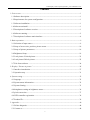
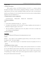
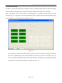
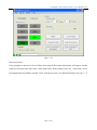
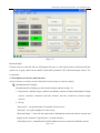
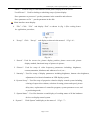
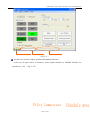
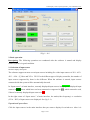
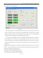
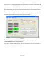
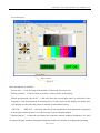
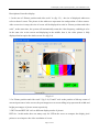
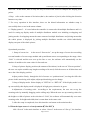
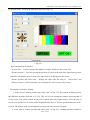
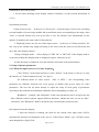
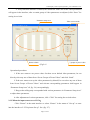
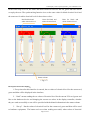
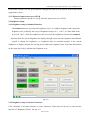
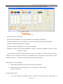
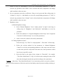
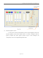
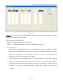
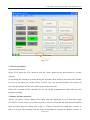
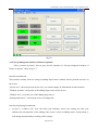
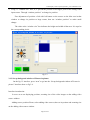
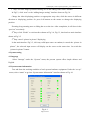
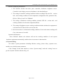
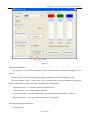
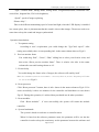
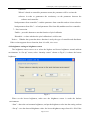
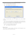
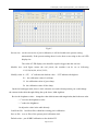
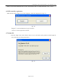
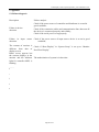
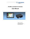
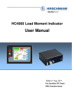
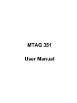
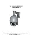
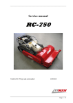
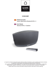
LED Display Control System
Software
User’s Manual V3.4.X
NO: QS2.436.0038ENSS
June, 2007
LED Display Control System_Software_User’s Manual V3.4.X
Copyright statement
LED controller software Uni-Master Ver3.4.X is valid from 1992 to 2007.
reserves their own rights.
This computer software is protected by Copyright Law and international pact.
Anyone who deliberately copies or spreads the part or whole of this program without
prior authorization shall be severely punished by civil and criminal laws. For those
who have violated it shall be punished within the scope of laws.
I
LED Display Control System_Software_User’s Manual V3.4.X
contents
1. Prior to use-------------------------------------------------------------------------------------------------- 1
1.1Software description------------------------------------------------------------------------------------ 1
1.2 Requirements for system configuration ------------------------------------------------------------- 1
1.3 Software installation ----------------------------------------------------------------------------------- 1
1.4 Software uninstall -------------------------------------------------------------------------------------- 1
1.5 Description of software version ---------------------------------------------------------------------- 1
1.6 Software running --------------------------------------------------------------------------------------- 2
1.7 Description of software main interface-------------------------------------------------------------- 4
2. Basic operation--------------------------------------------------------------------------------------------- 9
2.1 Selection of input source ------------------------------------------------------------------------------ 9
2.2 Setup of screen size, position, picture zoom------------------------------------------------------ 10
2.3 Setup of picture parameters ------------------------------------------------------------------------- 16
2.4 Brightness Setup ------------------------------------------------------------------------------------- 19
2.5 Lock picture /Unlock picture ----------------------------------------------------------------------- 23
2.6 Lock picture/Unlock picture ------------------------------------------------------------------------ 25
2.7 Exit from software ----------------------------------------------------------------------------------- 26
3. Display “Picture in picture”---------------------------------------------------------------------------- 26
3.1 Interface introduction-------------------------------------------------------------------------------- 27
3.2 Operation step ---------------------------------------------------------------------------------------- 31
4. System setting--------------------------------------------------------------------------------------------- 32
4.1 language ----------------------------------------------------------------------------------------------- 32
4.2 System status information--------------------------------------------------------------------------- 32
4.3 System Setting---------------------------------------------------------------------------------------- 33
4.4 bringhtness setting on brightness sensor ---------------------------------------------------------- 36
4.5 pixels correction-------------------------------------------------------------------------------------- 37
4.6 LED controller registration ------------------------------------------------------------------------- 39
4.7 Product ID--------------------------------------------------------------------------------------------- 39
5. Appendix--------------------------------------------------------------------------------------------------- 40
5.1 Failure diagnosis ------------------------------------------------------------------------------------- 40
5.2 Contact us --------------------------------------------------------------------------------------------- 40
I
LED Display Control System_Software_User’s Manual V3.4.X
1. Prior to use
1.1Software description
LED controller software(QS-TECH Uni-Master Ver3.4.X.X)is a customer platform
developed from display control system by Qingsong technology. It provides a convenient and
simple interface for the user, easily controlling the display content and its effect. Its main functions
include set-up of display size, device detection, input source detection, picture zooming, brightness
adjustment, video color adjustment, etc.
1.2 Requirements for system configuration
operational system:
Windows2000
Windows XP
Windows2003
1.3 Software installation
Install :
1.
In the software installation file folder, run “setup.exe”;
2. According to the instruction, click “Next Step” for software installation; after the interface of
“Installation Completed” appears, click “Close”;
3.
After the installation is completed, the icon for Uni_Master V3.4.X can be seen both in the
user’s desktop and “Start/Program”
。
1.4 Software uninstall
Description:
The deletion of Microsoft .NET Framework 2.0 can depend on the user’s need.
Uninstall:
Method 1: Run“setup.exe”in the installation program directly; select the option of “Remove
Uni_Master V3.4..X” and click “Complete” .
Method 2: Use “Add or Delete Program” in “Control Panel” and select “Uni_Master V3.4.X.” for
deletion.
1.5 Description of software version
Since Ver 3.4 can support different kinds of display control system,the function of V3.4 software
can vary with different control systems. This manual is the general description of V3.4 software.
The customer maybe find that some functions cannot be used in certain version because the
corresponding type of display control system cannot support those functions. In specific version,
those specific functions will not be described.
Page 1 of 43
LED Display Control System_Software_User’s Manual V3.4.X
1.6 Software running
In order to ensure the normal run of software, prior to running, firstly make sure that the display
control system has been properly connected with the computer and it has been electrified.
Run “Uni_Master 3.4.X”,in the menu of “Start/Program” or desktop shortcut mode, the start
interface (fig. 1-1) will appear:( because the hardware device shall be detected and initialized at the
start of software, it will take about one minute to start.)
(Fig.1- 1)
After software is started, the main interface will be entered. The software program will detect
the device automatically when started. When the detection on device and input source is
correct, both the functional buttons on the main interface and input source connected with the
system can be used. The main interface is shown as (fig. 1-2):
Page 2 of 43
LED Display Control System_Software_User’s Manual V3.4.X
(Fig. 1--2)
Search processor:
If the program is detected to be in failure when started, the hinted information will appear. and the
software will shown the demo state ,at the demo state all the buttons can’t use ; at this time, device
for manual detection shall be needed. Click “Search processor” for manual detection. See (fig.1-- 3)
Page 3 of 43
LED Display Control System_Software_User’s Manual V3.4.X
(Fig.1--3)
Research input:
If input sources on the left side are all displayed in gray or some input sources connected with the
system are in gray, input sources shall be detected by manual. Click “Research Input Source” for
re-detection.
1.7 Description of software main interface
The main interface of software provides standard and advanced options of interface display.
Standard interface display:
Standard interface display provides normal setup as shown in (fig.1-2).
1. Input source:display of type, mode(or resolution), position or status information of input
sources currently connected with the software and the switch-over between input
sources;
2. Set up:
“Screen size”: set up the number of modules for the screen
“Intensity”: set up the brightness for the screen
“Research Input ”: detect all the input source information connected with the system and
display in the column of “Input Source” of main interface;
“Search processor”: manually detect all the hardware devices connected with the system;
Page 4 of 43
LED Display Control System_Software_User’s Manual V3.4.X
“Black”:used for setup or cancellation of black picture displayed in the screen.
“Lock Picture”:Used for locking or unlocking setup of picture display.
“Save parameter to processor”: put the parameter in the controller and software.
“Save parameter to file ” : put the parameter in the disk.
Advanced interface display:
The advanced operation of screen setup is provided in the advanced interface. The interface
display is different from that of standard interface. see(fig. 1-4):
(Fig.1--4)
1. Input source :display of type, mode(or resolution), position or status information of input
sources currently connected with the software and the switch-over between input sources;
2. Set up:
“Screen…”, “Picture…”,“Intensity…”,“System Set up…” have the same functions
as those in the menu of “Set up” .
“Research Input”:used for detection on all the input source information connected with the
system and display in the column of “Input Source” of main interface;
“Search processor”:Used for manual detection on all the hardware device connected with
the system.
Page 5 of 43
LED Display Control System_Software_User’s Manual V3.4.X
“Black”:Used for setup or cancellation of black picture displayed in the screen.
“Lock Picture”:Used for locking or unlocking setup of picture display.
“Save parameter to processor”: put the parameter in the controller and software.
“Save parameter to file ” : put the parameter in the disk.
Main interface menu display:
¾ “File”:Click “File” and display “Exit” as shown in (fig. 1-5)for exiting from t
he application procedure;
(Fig.1--5)
¾ “Set up”:Click “Set up” and display as shown in the menu of (Fig.1-6);
(Fig.1-6)
1. “Screen”:Used for screen size, picture display position, picture zoom scale, picture
display method, functional setup of pictures in picture;
2. “Picture”:Used for setup of video frequency parameters including: brightness,
contrast,saturation, blackness and whiteness Level, etc.;
3. “Intensity”:Used for setup of display parameters including brightness, bottom color brightness,
adjustment of revision information on LED display system;
4. “System Set up”:Used for setup of properties related to display control system including,
coloring of supervision column, selection of testing picture and speed, picture
delay time, replacement of controller program, system parameter reset, and
re-positioning mode;
5. “System Status”:Used for detection on and display of working status of all the hardware
devices on display control system
¾ “System”: Click“System” and display as the menu of (Fig.1--7)
Page 6 of 43
LED Display Control System_Software_User’s Manual V3.4.X
(Fig. 1-7)
1. “Language”:selection of language used in the current interface. The
languages which can support currently are simple Chinese and English;
2. “Intensity sensor”: the Brightness Acquisition Device will collect the lowest and the
maximal brightness data when system have self-acting
collection function.
3. “Pixels correction”:set up the emendation information of every lamps on screen.
(It will show this option when the function of “single pixels correction”is using.)
4. “Picture in picture”: setup the superposition display about non-Video input source and
Video input source.;
¾ “help”: click “help” show in (Fig. 1-8)menu:
图 1-8
1. “ Register”: Register the LED controller;
2. “about”: display software system information and authorization;
The state bar
Three parts:
1. There are three lamps, ”C” ”D” ”B” are shown controller; distributer; Brightness
Acquisition Device, if is right, green show right .
2. Shown the speed of control operation.
3. If the operation is successful
Page 7 of 43
LED Display Control System_Software_User’s Manual V3.4.X
(Fig.1--9)
Switch-over between simple interface and standard interface:
In the top of input source of interface, select simple interface or standard interface for
switch-over;See (Fig.1--10);
Page 8 of 43
LED Display Control System_Software_User’s Manual V3.4.X
(Fig. 1--10)
2. Basic operation
Description:The following operations are conducted after the software is started and display
control system is in good condition.
2.1 Selection of input source
Interface display description:
The software supports at most seven input sources including five video input sources of AV1、AV2、
AV3、AV4、S_Video and VGA,DVI. For the different types of display controller, the number of
input sources supported by them is also different. When the software is started, input sources
connected with the system will be automatically detected.
In “Input source” of main interface, currently displayed input sources in high-green, displayed input
sources in green, those which have not been connected or supported in gray, which cannot be used,
if haven’t currently displayed input sources in red.
In the right corner of “Input source” of main interface, the mode(video frequency) or resolution
(VGA、DVI) of input sources are displayed. See (fig. 2-1).
Operational procedure:
Click the input sources in the main interface that you want to display for switch-over. After it is
Page 9 of 43
LED Display Control System_Software_User’s Manual V3.4.X
done successfully, the input source which is switched to is displayed in high-green, otherwise, the
current input source does not change.
(Fig.2-1)
Show all input sources:whether put all the input sources are set to be in the use status; if the
setup is in non-choose status, the system will automatically detect the input sources currently
connected with the controller. Non-existent input sources shall be set to be in the prohibited
status in gray and existing input sources in the usable status in green;
If the status is choosing status, the system will display that all the input sources are usable no
matter whether they are existing or not, and the input sources in red. If the user sets up a
non-existent input source, the system will indicate that this input source does not exist. If the user
sets up an existent input source, the system will set this input source as the current input source in
high-green;
Caution:After the input source is switched successfully, if the input source does not exist for other
reasons (eg. Power disconnection), the status column will suggest that the current input source
does not exist and the color will show in red.;
2.2 Setup of screen size, position, picture zoom
2.2.1 Setup of screen size in the standard interface
Page 10 of 43
LED Display Control System_Software_User’s Manual V3.4.X
Setup of screen size in the standard interface only needs setup of the number of range module of
screen as shown in fig. 2-2. The system will set up the screen size according to the number of range
module. If the input source is of video information, the video size will be automatically zoomed into
the designated module. The screen size set up in the simple interface will not change the starting
position of input source.
If “Link” in the size of module is selected, the number of module ranges will the same. Otherwise.
the number of module ranges and columns will be effect with each other.
(Fig.2-2)
2.2.2 Setup of screen size, position and zooming position of advanced interface
a. When the input sources are of video frequency
Click “Screen” of main interface or select “Screen” in the menu of “Set up”, the interface of
“Screen Set up” will pop up from the system (fig. 2-3):
Page 11 of 43
LED Display Control System_Software_User’s Manual V3.4.X
Zoom rolling strip
Status column
(Fig.2-3)
Brief introduction of interface:
“Screen Size”:Used for setup of the number of line mode for screen size;
“Picture position”:Used for setup of position of video picture in the display.
“Picture position and video scale”
:valid only when the current input source is selected as video
frequency. Used for adjustment of zooming scale of video picture in the display and at the same
time display of effect after the picture is actually zoomed and deviated.
“DPT On”, “DPT Off”:valid only when the picture dynamism or non-dynamism is supported
in the display control system. It is used for setup of picture display method
“Display pattern”:it cannot be used unless the controller connects multiple distributors. It is used
for setup of display method of multiple distributor module sets includes overlapping and jointing;
Page 12 of 43
LED Display Control System_Software_User’s Manual V3.4.X
Description of interface display:
1. In the area of “Picture position and video scale” in (fig. 2-3),the size of displayed white area
refers to that of screen. The picture in the white area represents size and position of video sources.
After screen size is setup, the size of screen will be displayed in scale in “Picture position and video
scale”, at the same time, the system will automatically zoom the video frequency, enabling it to be
in the same size as the screen and displaying in the middle, that is, the video picture is fully
displayed and occupies the whole screen. See (fig.2-4)
(Fig.2-4)
2. In “Picture position and video scale” (fig. 2-4), X and Y refer to the position of left top corner of
current input source in the screen, the percentages next to zoom rolling strip represent the width and
height percentages of picture zoom respectively
3. DPT On and DPT Off: refer to different display modes of picture.
DPT On:in this mode, there are many ways for LED in the screen to compose the display pixel
points so as to improve the video resolution of screen.
Page 13 of 43
LED Display Control System_Software_User’s Manual V3.4.X
DPT Off:in this mode, there is only one way for LED in the screen to compose the display pixel
points.
4. Step:refers to the amount of deviation (that is, the number of pixels) after clicking the direction
buttons every time.
5. For every operation in this interface, there are the hinted information on whether setup is
successfully done or nor in the status column.
6. “Display pattern”:it is used when the controller is connected with multiple distributors and it is
used for setting up display mode of multiple distributor module sets including overlapping and
joining modes. Overlapping means the same content of multiple distributors and joining means that
the whole picture is displayed by joining multiple distributor module sets which individually
display one part of the whole picture;
Operational procedure:
1. Setup of screen size: in the area of “Screen size”, set up the range of screen size according
to actual number of screen range module and up and down arrows corresponding to the range; when
“Link” is selected and the user sets up the line or row, the software will automatically set the
number of module as the same value for line and row.
2.Setup of picture display position (the amount of deviation): in the area of “Picture position”,
the user sets up the suitable step length according to his need, click the arrows at all directions and
move the video display position
Adjust position fleetly: through the left of mouse on “position/zoom”, moving the full-color
picture in this area doing wide adjust, adjust position doing precise change.
3.Setup of display mode: Select display of “DPT On” or “DPT Off”. If the display mode is set
up successfully, this display mode is displayed in high-green, otherwise in green.
4.Adjustment of zooming scale:According to the requirements, the user can set up the
zooming scale by manually dragging on the rolling strip. When the user sets up zooming values for
the height or width of picture at the selection of “Link”, the software will automatically set a same
zooming value for height and width, that is zoom them in the same scale.
5.After the setup is completed, close this interface and return to the main interface.
b. When the input source is of on-dynamism(VGA/DVI)
click “Screen” in the main interface or select “Screen” in the menu of “Set up”, the interface
Page 14 of 43
LED Display Control System_Software_User’s Manual V3.4.X
of “Screen Setup” will pop up from the system. See( fig.2-5):
(Fig.2-5)
Brief introduction of interface:
“Screen Size”:Used for setup of the number of range module for the screen size;
“Picture position”
:Used for moving the position of screen in the non-video input source picture
and make sure that the area for non-video input sources is displayed in the screen.
“Picture position and video scale”
:Display the effect after the setup of
“Screen Size” and
“Picture position”, which means the screen displays the area for non-video picture.
Description of interface display:
1. In the area of “Picture position and video scale” of (fig. 2-5), the content of display picture
has different meaning from that in 2.2.2.a. The size of red rectangular column represents that of
set-up screen. The picture stands for the size of whole non-video input sources. After the size of
screen is set up, the size of screen will be displayed in the area of “Picture position and video scale”
in scale. The picture in the red rectangular area represents the content of display.
2. In the area of “Picture position and video scale” of (fig.2-5), zooming operation cannot be
Page 15 of 43
LED Display Control System_Software_User’s Manual V3.4.X
conducted for non-video picture.
3. For the other meanings of the display content of interface, see the relevant information in
2.2.2.a.
Operational procedure:
1.Setup of screen size: in the area of “Screen size”, set up the range of screen size according
to actual number of screen range module and up and down arrows corresponding to the range; when
“Link” is selected and the user sets up the line or row, the software will automatically set the
number of module as the same value for line and row.
2. Displayed picture area for non-video input sources: in the area of “Picture position”, the
user sets up the suitable step length according to his need, click the arrows at all directions and
move the video display position
3.Setup of display mode: Select display of “DPT On” or “DPT Off”. If the display mode is
set up successfully, this display mode is displayed in green, otherwise in red.
4.After the setup is completed, close this interface and return to the main interface.
2.3 Setup of picture parameters
2.3.1 When the input sources are of video frequency;
Click “Picture” in the main interface or select “Picture” in the menu of “Set up” to enter
the interface of “Video Parameter Set up”. See fig.2-6
For different modes of video sources (PAL or NTSC),the corresponding video
parameters are different. Software has seven groups of default video preset values for video
parameters. The user can use them directly or adjust the setup of each group of parameters
according to his need and environmental conditions such as daylighting, weather, etc.
“Brightness”, “contrast” and “Saturation” in the video parameters can be set up by the user.
Since different control systems support different functions, whether the user can set up “Hue”,
“blackness” and “Whiteness” shall be decided by the current display control system.
Description of interface display:
1. After the software is running, the mode for the current video input source will be
automatically detected and displayed in the area of “Video Source Mode” (fig. 2-6)Video source
mode displayed in (fig2-6) PAL.
Page 16 of 43
LED Display Control System_Software_User’s Manual V3.4.X
2. Every time this interface is entered, the current set values for all the video parameters
will appear in the interface; after a certain group of video parameters are adjusted, click “Store” for
storing its revision.
Parameter setup area
Status column
Video source mode
7 groups of preset value
(Fig.2-6)
Operational procedure:
1. If the user wants to use preset values for those seven default video parameters, he can
directly select any one of them from “Seven Groups of Preset Values” and click “Send”.
2. If the user wants to set up the video parameters by himself, he can select any one of them
from Seven Groups of Preset Values” and relevant corresponding parameters shall appear in
“Parameter Setup Area” of( fig. 2-6) correspondingly.
3. Drag on the rolling strip corresponded with various parameters in “Parameter Setup Area”
to adjust these parameters.
4. After adjustment of various parameters, click “Click” for storing the revised values.
2.3.2 When the input sources are of VGA;
Click “Picture” in the main interface or select “Picture” in the menu of “Set up” to enter
into the interface of “VGA picture Set up”. See (fig. 2-7).
Page 17 of 43
LED Display Control System_Software_User’s Manual V3.4.X
In the color setup of VGA, the white and black electrical levels for the red, green and blue can be
set up by the user. The synchronizing function is to set the same value for black electrical level and
the same one for white electrical level for these three colors;
Red for black and
white electrical level
Green for black and
white electrical level
Blue for black and
white electrical level
Status column
(Fig.2-7)
Description of interface display:
1. Every time after this interface is entered, the set values of electrical level for the current red,
green and blue will be displayed in the interface;
2. “Send”means sending the set values of electrical level for the current VGA red, green and
blue to the hardware device and changing the current set values in the display controller; whether
they are send successfully or not will be provided with the hinted information in the status column.
3. “Set up”: Put the values of electrical level for the current red, green and blue will be send
to hardware equipment;The button can’t use when sending successful, when values of electrical
Page 18 of 43
LED Display Control System_Software_User’s Manual V3.4.X
level for the current VGA red, green and blue changed the software will send the setup to hard ware
equipment by itself.
2.3.3 When the input sources are of DVI;
Picture parameters needn’t be set up when the input sources are of DVI;
2.4 Brightness Setup
2.4.1 Brightness setup of standard interface
On standard interface just setup the brightness (fig. 2-8), offshoot brightness and component
brightness scale of display, the scope of brightness setup is 0%-100%, 0%show dark at the
best of all, 100% show the brightness at the best of all, the brightness which at the standard
interface show the current brightness for display, through cursor beat the brightness data add and
minish to change the brightness, The brightness data on standard interface is the current
brightness of display, through the moving mouse adjust the brightness data, it has hint information
on the status bar to show whether the brightness is ok.
fig. 2-8
2.4.2 Brightness setup of advanced interface
Click “Intensity” in the main interface or select “Intensity” in the menu of “Set up” to enter into the
interface of “Brightness Table”. See fig. 2-9.
Page 19 of 43
LED Display Control System_Software_User’s Manual V3.4.X
Brightness control includes manual control, timing control and automatic control.
Status column
fig. 2-9
Brief introduction of interface:
RGB:adjust the brightness of red, green and blue in the display individually.
Gamma: adjust the correction indexes of red, green and blue in the display individually.
Brightness: Adjust the brightness of display.
Backcolor: Adjust the brightness of color base of display.
Brightness control: Select manual brightness control or automatic brightness control or timer
brightness control.
Timer:Valid only when the timing control is set up. Preset all the correction parameters and their
starting time. The software will send the corresponding corrected parameters to the display control
system according to the preset correction information and starting time.
Description of interface display:
1. Values under the rolling strips are the currently set parameters;
2. Whether they are sent successfully or not is hinted in the status column.
Operational description:
Operational procedure:
1.
Set up the component brightness scale:Drag on red, green and blue rolling strips in
Page 20 of 43
LED Display Control System_Software_User’s Manual V3.4.X
“RGB” in (fig 2-9) individually to revise the corresponding parameters; if “Link” is
selected, any parameter from “RGB” can be selected and other components will change
with it and their values are same.
2. Set up component correction coefficients:Drag on red, green and blue rolling strips in
“Gamma” in (fig 2-9) individually to revise the corresponding parameters; if “Link” is
selected, any parameter from “Gamma” can be selected and other components will change
with it and their values are same.
3. Brightness setup:
a. Manual brightness setup:
¾
Select "Manual Brightness” from “Adjust pattern” in (fig2-9) and drag on
rolling strips of “Brightness” and “Backcolor” individually to revise the
parameter.
¾
Follow the methods of “Component Brightness Scale Setup” and “Component
Correction Coefficient Setup” to revise their parameters;
¾
After revision, the software will send by automatism.
b. Timing brightness control
Choose the (fig. 2-9) “Timer” in “Adjust pattten”, “Time-table” will be using.
¾
Follow the revision method for the parameters in “Manual Brightness
Control” to revise the corresponding parameters. After setup, move the cursor
to other time period for setup and at the same time, those parameters which
have been set up will be stored.
¾
Select the block to the right of time column in “Time-table”, for example,
“Time Start Identification” in fig.2-10 which means starting the setup of this
time and selecting the started time period according to the requirement.
Caution:
Only when “Time Start Identification” for a certain time period is set up, the software
will send all the parameters of this time period to the display control system according to timing, or
won’t.
Page 21 of 43
LED Display Control System_Software_User’s Manual V3.4.X
Currently selected
time period
Starting identification
of time period
Fig. 2-10
(3)
Automatic brightness control:
¾ If the system is connected with brightness collector, then the brightness collector has
automatic brightness control and the display interface is as follow. “Intelligent” under the
control of “Manual” and “Timer” appears as shown in fig.2-11. Select “Intelligent” and
“Timing Setup” turns to be in inapplicable/applicable status.
Page 22 of 43
LED Display Control System_Software_User’s Manual V3.4.X
Fig. 2-11
Caution: Only when it is of fiber and brightness collector works normally, “Interlligent” can work,
otherwise, “Interlligent” will not appear;
2.5 Lock picture /Unlock picture
“Black”sets up the black color for LED display;
“Unblack” means canceling black color when LED display is in black;
Operational description:
1. Click “Black” in the main interface (fig. 2-12). Whether the setup is successful or not will be
hinted in the status column. If the setup is successful, the screen is black and at the same time,
the button of “Black” turns to be “Unblack”, see (fig. 2-13), otherwise, the display does not
change and “Black” will not appear to be “Unblack ”
2. Click “Unblack” in the main interface (fig. 2-13). Whether the setup is successful or not will
be hinted in the status column. If the setup is successful, the screen will directly display the
currently selected input source picture and at the same time, the button of “Unblack” turns to
be “Black”, see (fig. 2-12), otherwise, the display is black and “Unblack” will not appear to
be “Black”.
Page 23 of 43
LED Display Control System_Software_User’s Manual V3.4.X
Status column
(Fig.2-12)
Status column
(Fig.2-13)
Page 24 of 43
LED Display Control System_Software_User’s Manual V3.4.X
2.6 Lock picture/Unlock picture
Lock picture is to make the current picture in the screen static;
Unlock picture enables the picture in the screen to be played normally when locked;
Operational description:
1. Click “Lock picture” in the main interface (fig. 2-14) to lock the picture. Whether the setup
is successful or not will be hinted in the status column. If the setup is successful, the screen will
have a static display and at the same time, the button of “Lock picture” turns to be “Unlock picture”,
see (fig.2-15), otherwise, the display is not static and “Lock picture” will not
become “Unlock
picture”.
Status column
(Fig.2-14)
2. Click “Unlock picture” in the main interface (fig. 2-15) to unlock the picture. Whether the
setup is successful or not will be hinted in the status column. If the setup is successful, the screen
will play the picture and at the same time, the button of “Unlock picture” turns to be “Lock
picture”, see( fig. 2-14), otherwise, the display is static and “Unlock picture” will not become
“Lock picture”.
Page 25 of 43
LED Display Control System_Software_User’s Manual V3.4.X
Status column
(Fig.2-15)
2.7 Exit from software
Operation introduction:
Select “Exit” under the “File“ menu or click the “close” button on the main window to exit the
software.
If you change the parameter or setting during the operation, there will pop out prompt info whether
to save it or not when you exit the system. If select “save” the present parameter, the system will
save into the software and into the control system at the same time.
Notice: Do not swith off the controller, do not cut off the communication cable while save the
parameter setttings.
3. Display “Picture in picture”
“Picture in picture” means adding video input onto the displaying area of Non-video input
(VGA/DVI). If you want to set “picture in picture”, there is a need that the Non-video(VGA/DVI)
input and video input are existing refer to fig. 3-1. If there is one doesn’t exiting, there “picture in
piture” is in grey color meaning it can not work. If both input are existing, the “picture in piture” is
Page 26 of 43
LED Display Control System_Software_User’s Manual V3.4.X
in Green color.
(fig.3-1)
3.1 Interface introduction
3.1.1 Swith “picture in picture” on main interface
When the “picture in picture” is existing, select the “Pip” button to swith.
If the present input is not “Pip”, that button is in green color.
If the present input is “Pip”, that button is in brighter green color. And the input for forground
and background are in brighter green color shown as fig.3-2
Page 27 of 43
LED Display Control System_Software_User’s Manual V3.4.X
(fig.3-2)
3.1.2 Set up backgroud window of Picture in picture
Select “picture in picture” then it goes into the interface of “Set up backgroud window of
Picture in picture” show as fig.3-3
Interface introduction:
This interface mainly focus on setting of adding input sourse window and its position and size on
the screen
“Screen size”: show the present screen size, you cannot change its information on this interface.
“Window position”: the positio of the adding input source on the screen
“Window size”: to set the size of the adding input source
“background source”: select input source as background
Interface displaying introduction:
1. in fig.3-3, “window size” area, the white part indicates screen size setting, the blue part
indicates the size/position of the adding video source. After set adding source size/position, it
will change automatically according to the settings.
Page 28 of 43
LED Display Control System_Software_User’s Manual V3.4.X
2. in fig.3-3 “window size” area, X, Y present the position of left upper point of the adding video
input source. Through “window position” to change its position.
Fast adjustment of position: click with left button on the mouse on the blue area in that
window to change its position to large extent, then use “window position” to make small
change.
The value at the “window size” bar indicates the height and width of that area. It’s eaqul to
the corresponding pixels.
fig.3-3
3.1.3 Set up backgroud window of Picture in picture
On the fig.3-3 interface, press “next” to go into the “Set up backgroud window of Picture in
picture” interface show as fig.3-4.
Interface introduction:
It serves as to set displaying position, zooming size of the video images on the adding video
source window.
Adding source position/Zoom:select adding video source, then set its positon and zooming size
on the adding video source window
Page 29 of 43
LED Display Control System_Software_User’s Manual V3.4.X
“Picture in picture Preview”: preview the effect after setting.
Interface displaying introduction:
1. In fig.3-4 “video source selection”, the system will detect existing video input source.
Non-existing video input source is shown in grey color which means it’s invalid. The existing
input is shown in green color. Present selection of the adding input source is shown in brighter
green.
If the system has only one video input source, then it will set this video input source as adding
input source.
2. In fig. 3-4 “zoom” area, the blue part indicates the size of video source window, the part below
this window indicates the adding input source.
3. After setting the video position, the “fore” area in the “preview” area will change automactially
according to the setting.
4. When after setup the zooming of VGA picture, the “fore”picture will adjust by itself setup data
in”adding the preivew”area.
5. After set all the info. in this interface, there will pop up info. whether it’s saved successfully in
the Status column.
6. “Set up”: send the value to the hardware. When it’s sent successfully, the buttom presents
invalid. When the setting changes, the system will send parameter automatically.
(Fig.3-4)
Page 30 of 43
LED Display Control System_Software_User’s Manual V3.4.X
3.1.3
Main interface
After setting on the “picture in picture” shown in Fig 3-4., click “Finish” back to main interface
shown as Fig. 3-5.
Fig. 3-5.
Interface display introduction:
In fig.3-5 “input source”, the non-video input source and adding video source will be in green
color. It indicates that the present displaying is in “picture in picture”.
3.2 Operation step
1st Step: select input source as background
click “Set up backgroud window of Picture in picture” interface to choose “DVI” or “VGA”as
background.
2nd Step: set size/position of video source window
According to user’s requirement, drag the Height & Width sliding bar to set the size in the
“Window size” area. In the “Window position” area, set approporite step value, click arrows in
different direction in order to set the position.
Page 31 of 43
LED Display Control System_Software_User’s Manual V3.4.X
3rd Step: set video images position/zooming size on the adding video source window
In Fig3-3, click “next” to the “adding images setting” interface shown as Fig 3-4.
Change the video displaying position: set appropriate step value, click the arrows in different
direction to displaying position. Or press left buttom on the mouse to change the displaying
position.
Zooming: drag zooming area or sliding bar to set the size. After completion, it will show in the
“preview” area timely.
4th Step: click “Finish” to exit interface shown as Fig.3-4, Fig.3-3, then back to main interface
shown as Fig.3-5
5th Step: cancel “picture in picture” displaying
In the main interface Fig.3-5, click any valid input source at randam, it cancels the “picture in
picture”, the selected input source will display on the screen at the same time. Or switch the
“picture in picture” button.
4. System setting
4.1 language
Select “lanuage” under the “System” menu, the present system offers simple chinese and
English.
4.2 System status information
Test and show the working condition of each system hardware equipment. Under the “set up”
menu, select “status” to go into “System status information” interface shown as Fig. 4-1
Fig. 4-1
Page 32 of 43
LED Display Control System_Software_User’s Manual V3.4.X
Interface displaying introduction:
1、The interface devides into three parts: controller, distributor, brightness sensor.
Controller is the display processor, distributor is the data distributor.
2、The testing of controller working condition includes working PCB serial No. , version
info., and working condition of each component (configuration files, parameter files,
FPGA1, FPGA2, SAA7114, THS8083.
3、The testing of distributor working condition includes PCB No., verison info., and
working condition of each main component(FPGA).
4、The testing of brightness sensor working condition includes whether the equipment is
well connected, PCB serial No. and version info.
5、Red color means it’s in abnormal working condition. Green color means working well.
Grey color means it’s invalid.
Operation introduction:
Press “Refresh” buttom, the software will test the working condition of each system
hardware equipment automatically, and then show its outcome in that interface.
4.3 System Setting
Set relative system parameters including Monitor, testing, picture delay, syststem reset,
module reset, default system parameter.
Click “Setting” on the main interface or select “System setting” under the “setting” menu to
go into “System” interface shown as Fig. 4-2
Page 33 of 43
LED Display Control System_Software_User’s Manual V3.4.X
Status column
Fig. 4-2
Interface introduction:
“Test pattern”: to test relative parameter of the hardware system including testingtype, speed
and etc.
“Picture delay”: to make the displaying images synchronous with the displaying sound
“Preview monitor frame”: set the color of the monitor frame to check whether the displaying
images in the monitro frame is the same with that in the LED display.
“Reset processor”: to restart the controller and distributor
“Reset module” : to reset the module controller
“system benchmark” :the system parameter is set basing on LED controller or software.
“Pixels correction”:set pixels correction“enable”or”disenable”.
Interface displaying introduction:
“Testing pattern” :
Page 34 of 43
LED Display Control System_Software_User’s Manual V3.4.X
“Type”: normal mode, buring mode, testing mode, red/green/blue/white, honizontal line,
vertical line, diagonal line, 256 levels brightness,
“Speed”: speed of images replacing
“Picture delay” :
Due to the different transmitting speed of sound and light, when the LED display is installed
in a remote place, there is phenomenon that the sound is slower than images. Then users need to set
some time to keep the sound and images synchronized.
Operation introduction:
1、Test pattern setting
According to user’s requirement, you could change the “Type”and “speed”. After
setting successfully, there is corresponding info. in the status column show as Fig.4-2.
2、Preview monitor frame
You could drag “Red”, “Green”, “Blue” sliding bar to select your favorite color, and
then select “Show preview monitor frame”. There is relative clue info. in the status
column after sucessful setting shown as 4-2.
3、Picture delay
You could change the frame value of images, the software will send by itself.
When the consumer operation contentment,the setup data of picture lingering will show
on status bar Fig.4-2.
4、Reset processor
Click “Reset processor” buttom, there is info. shown in the status colomn as Fig.4-2. If it
resets sucessfully, it takes two minutes for the controller and distributor to reset shown
Fig.4-2. During this operation, it’s advised that you should not do other operations.
5、Reset modules
Click “Reset modules” , if reset successfully, the system will restart the module
controller.
6、System benchmark
The system is based on software or controller norm.
When it’s based on the software parameter norm, the parameter will be set into the
controller in order to keep the consistency on the parameter between the software and
Page 35 of 43
LED Display Control System_Software_User’s Manual V3.4.X
controller.
When it’s based on controller parameter norm, the parameter will be set into the
software in order to guanrantee the consistency on the parameter between the
software and controller.
“load parameter from controller”: read the parameter from controller and set it into software.
“load parameter from files”:to load parameter files from disk,andthen send it to controller.
7、Pixel correction
Enable:press this buttom to start the function of pixel calibratio
Disenable:to show whether the pixel calibration is valid or not.
Notice: Whether the system has above function is set by the type of controller and distributor.
If the version supports abover function, then it’s valid, vice versa.
4.4 bringhtness setting on brightness sensor
The brightness sensor serves as to select the highest and lowest brightness around ambient
envrionment. In “Set up” menu, select “intensity sensor” shown as Fig.4-3, it shows the lowest
brightness.
Fig.4-3
When set the lowest brightness, make sure the brightness sensor is under the darkest
environment.
“Start”:detect the environment brightness, and put the brightness value into the setting coulom
“Set up”:save the detected brightness value,the lowest brightness ranges from 0%--20%.If the
Page 36 of 43
LED Display Control System_Software_User’s Manual V3.4.X
detected value is out of the range, it’s need to set the lowest value manually.
“Next”:go to the highest brightness setting interface
“exit”: exit the “brightness sensor setting” interface
Click “next”to the highest brightness setting shown as Fig.4-4,
Fig.4-4
When set the highest brightness, make sure the brightness sensor is udner the brightest
environment.
“Start”:detect the environment brightness, and put the brightness value into the setting colomn.
“Set up”:save the detected brightness value,the highest brightness ranges from 60%--100%. If
the detected value is out of the range, it’s need to set the highest value manually.
“previous”:go to the lowestt brightness setting interface
“exit”: exit the “brightness sensor setting” interface
4.5 pixels correction
Pixel correction is to adjust the brightness of LED lamps of the LED display.Select “pixel
correction” under the “system” menu shown as Fig.4-5
Page 37 of 43
LED Display Control System_Software_User’s Manual V3.4.X
Fig.4-5
Screen size:set the screen size of pixel calibration, it will be loaded to the present setting
automatically. If the present setting doesn’t exist, then set accoring to the real LED
display size.
The value of LED display size should be equal or bigger then the real size.
Module size: each figure means the real pixels, the modules can be set as following
1*1,2*2,4*4,8*8,16*16,32*32;
Modify value :0-255;“0” indicates the darkest value、“255”indicates the highest.
R :the calibration value of red lamp
G:the calibration value of green lamp
B:the calibration value of blue lamp
On the left and upper table, there is info. aobut the row and colomn position,you could change
the content in the table through sliding the up & down, left& right bar.
Revise the brightness value: change the value which is same with oringal value, that it’s the new value.
“+” increase the brightness value
“-”reduce the brightness
Or adjust the value in the table directly.
Load from file:load from files which has existing pixel calibration
Save to file:save as files of the present pixel calibration info.
Default value:put all RBG calibration to the default 255.
Page 38 of 43
LED Display Control System_Software_User’s Manual V3.4.X
Setup: set present calibration info. to the LED display, there is setting outcome in info. colomn.
4.6 LED controller registration
LED controller need to regist to run. Select “Register” under the “help”shown as Fig. 4-6
Fig. 4-6
“Register”to load enrolled files to regist controller
“cancel” to exit the registration interface
4.7 Product ID
Under the “Help” menu, select “about” shown as 4-7 to check the system product ID. When apply for
new product ID, you need present ID No.
Fig. 4-7
Page 39 of 43
LED Display Control System_Software_User’s Manual V3.4.X
5. Appendix
5.1 Failure diagnosis
Description
Failure analysis
Failure in device
detection
Check if the power source of controller and distributor is on and in
good condition;
Check if the connection cables and communication lines between all
the devices is connected properly and reliably;
Check if the serial port is set up properly;
Failure in
detection
input
source Check if the power source of input source device is on an in good
condition;
The content of monitor is
Check if “Data Display” in “System Setup” is set up as “Monitor
different from that of
Port Fiber Display”
display screen.
Black screen appears but
the content displays in the
monitor and the indicator The authorization of system is in due time.
light for controller MPU is
flashing
5.2 Contact us
After-service hotline:029-81881316
Company’s website:www.qs-tech.com
Company’s address:Qingsong technology, C2 New Mainland Industrial Park, Road Chuangye,
New area of High-tech Zone, Xi’an
Postal code:710065
Page 40 of 43