1
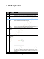
www.leetro.com CBS3 User Manual (V1.0) Table of Content 1 2 3 Breif Introduction of CBS3......................................................................................................... 2 Installation Guide ...................................................................................................................... 3 2.1 Equipment Composition............................................................................................ 3 2.2 Installation of MPC08WZ........................................................................................... 4 2.2.1 Installation of Control System ........................................................................... 4 2.2.2 Uninstallation of software ................................................................................. 7 Guide for Software using........................................................................................................... 8 3.1 Instruction of Unit ..................................................................................................... 8 3.2 Main Interface ........................................................................................................... 8 3.2.1 Toolbar............................................................................................................... 8 3.2.1.1 Equipment Mutiple Setting ....................................................................... 8 3.2.1.2 Device Test .............................................................................................. 15 3.2.1.3 Craft-Param. Setting ................................................................................ 17 3.2.1.4 Process Taskbar ....................................................................................... 19 3.2.2 New File, Open File, Save File Toolbar ............................................................ 19 3.2.2.1 New File ............................................................................................ 19 3.2.2.2 Open File .......................................................................................... 20 3.2.2.3 Save File ............................................................................................ 20 3.2.3 Edit Toolbar ..................................................................................................... 20 3.2.3.1 Show Data Range ............................................................................... 20 3.2.3.2 Show Joint ......................................................................................... 21 4 5 6 3.2.3.3 Hide Joint .......................................................................................... 21 3.2.3.4 3.2.3.5 Text .................................................................................................... 21 Size .................................................................................................... 22 3.2.3.6 3.2.3.7 3.2.3.8 3.2.3.9 3.2.3.10 Zoom ................................................................................................. 22 Mirror ................................................................................................ 23 Move/Zoom .................................................................................... 24 Select ................................................................................................. 24 Move.................................................................................................. 24 3.2.3.11 Add Joint ........................................................................................... 25 3.2.3.12 Delete Joint........................................................................................ 25 3.2.4 Node Edit Toolbar ............................................................................................ 25 3.2.5 State Monitorbar ............................................................................................. 27 3.3 Parameter Backup ................................................................................................... 27 3.4 Software Starting Screen Edit .................................................................................. 27 Bend Table............................................................................................................................... 28 4.1 Flap Arc Table .......................................................................................................... 28 4.2 Flap Line Table ......................................................................................................... 29 4.3 Extrusion Arc Table .................................................................................................. 30 Software Decoding .................................................................................................................. 32 Words Explanation .................................................................................................................. 33 1 1 Breif Introduction of CBS3 CBS3 is an advanced software which support 5-Bend Type, 6-Slot Type and 2-Feed Type. CBS3 can support most of machine for aluminum profile, stainless steel and iron word in the market. Features ●File format DXF<ASCII >、PLT、AI<Under 7.0 > ●All typeface word input ●Software automatic smooth tracking ●Output PLT file provided for process base cover, guarantee bending word and base cover the same data source, to improve the coin ●Function of zoon out and zoon in, compensation of simplified Chinese character. ●Add or delete joint ●Support Windows7(32bit)/XP ●Max 7 axis control ●Support software authority using time management. ●Support customize language ,company information, power on Logo. ●Data base of bending table. ●Safe monitor of processing ●Interference warning before process. (for press bending model) ●Free combination of feed type, slot type and bend type 2 2 Installation Guide 2.1 Equipment Composition The complete equipment includes hardware (controller board V0.4.101) and software. Hardware: MPC08B (V0.4.101)(1 unit) EA1616B(1 unit) P62(1unit) Adapter plate P37-05(1 unit) Adapter cable C62-2M(1) Adapter cable C37-2M(1) Adapter cable C40-0.2M(1) Instruction of software catalogue: Serial No. 1 File and Document Function Location Software\Language-CN\langua Language file Software\Language-CN\ ge.ini of Chinese interface 2 Software\Language-EN\langua Language file ge.ini of English Software\Language-EN\ interface 3 Software\language.ini Language file Software\ of present interface 4 Software\interface.jpg Starting image Software\ 5 Software\company.inf Company Software\ Information 6 Software\CalMath.exe Calculator of Software\ curvature semi -diameter 7 Software\*.bear_ratb Extrusion arc Software\ bend table 8 Software\*.flap_rastb Flap arc bend Software\ table 9 Software\*.flap_aatb Folding angle Software\ bend table 10 Software\Craft.cfg Craft Software\ parameter file 11 Software\Machine.cfg Mechanical Software\ parameter file 12 Software\MPC08.dll DLL Software\ 13 Software\TTFPrase.dll DLL Software\ 3 Note 14 Software\GraphHD.dll DLL Software\ 15 Software\elitee.dll DLL Software\ 16 Software\CBS3.exe APP Software\ 2.2 Installation of MPC08WZ Please see the <MPC08B User Manual.Pdf> 2.2.1 Installation of Control System For Windows 98、2000、XP、WIN7(32bit), when MPC08 plug in PCI of computer, The system will automatically detect ,show “muti-media video controller”. The installation of drive program, function library and demo program could be complete as following steps. 1) Please click ‘cancle’ when ‘unknown PCI’ appears. 2) Run MPC03SP setup.exe in the “program files” 3) click ‘next step’. Choose installation module: drive program, app program(include function library and demo program), select both for default . 4 4) Please click ‘next step’ to start installation. 5) Please click ‘complete’ 5 6) system require restart computer, click ‘yes’. The installation of drive program will be complete after restart. 7) The tips will appear when restart under Windows XP, please choose the 3rd one that is ‘no ,for temporally’ 8) Choose choice 1: ‘Automatic Install ( Recommend) (I)’. Click ‘next step’ to complete installation. 6 2.2.2 Uninstallation of software Two methods of uninstallation: 1)Run ‘unwise.exe’ in MPC08 installation document. 2)Run ‘ Add/Remove’ to uninstall MPC08 in the control panel of the system. 7 3 Guide for Software using 3.1 Instruction of Unit All units used in software is subject to units below. Length(distance): mm Speed: mm/s, O/s Acceleration: mm/s2,O/s² Angle: (O) Time: (s) 3.2 Main Interface Process task, Machine Configuration、 Parameter Setting、Equipment Test Toolbar N ew, Open, Save E joint dit State Monitor According to the screenshot, the main interface includes 5 parts. 1、 Process task, Machine Configuration、Parameter Setting、Equipment Test Toolbar 2、 New, Open, Save 3、 Edit 4、 Edit joint 5、 State Monitor Function of toolbar listed below. 3.2.1 Toolbar 3.2.1.1 Equipment Mutiple Setting 1. Machining Set 8 Edit Equipment general Setting default setting can not change . Please click and enter password to edit settings. 1) Bend type Definition of front side and reverse side of bender Origin Reverse side of bender αNegative empty angle Bending rod 1 Zero point Material Bending rod 2 βForward empty angle Front side of bender Single flap bend, Single Extrusion Bend,Separate Flap Bend,Coupled Extrusion Bend, Coupled Flap Bend Single flap bend:Use the same bending rod for Front side flap bend and reverse side flap bend. When use front side flap bend, the bending rod move down to safe position. The bending rod drive by motor to the back of material. Then the bending rod arises to flap the bend in front side. On the contrary, flap bend in reverse side could be complete. Single Extrusion Bend:Used the same bending rod for front and reverse side extrusion bend. When use front side extrusion bends, the bending rod falls on safe position. The bending rod turns to the back of material with the power of motor. After that, the bending rod arises then to extrusion the bend in front side. On the contrary, extrusion bend in reverse side could be complete. Separate Flap Bend:Used the different bending rod for Front and reverse side separate flap bend . When use front side separate flap bend, the reversion side bending rod falls on safe position. Then the motor drive bending rod to the back of material. then, the reversion side of bending rod arises then to do separate flap bend in front side. On the contrary, separate flap bend in reverse side could be complete. Coupled Extrusion Bend: The bending rod will not move. Used the different bending rod for Front side coupled extrusion bend and reverse coupled extrusion . When use front side couple 9 extrusion bend, the reverse side of bending rod endures the main force. On the contrary, when use reverse side couple extrusion bend, the front side of bending rod endures the main force. Coupled Flap Bend: The bending rod will not move. use the different bending rod for Front and reverse side flap bend. When use front side flag bend , the reverse side of bending rod endures the main force. On the contrary, when use reverse side couple extrusion bend, the front side of bending rod endures the main force. Bending rod up/down check: when select the function,”I/O setting” upper/lower limit switch must connect the corresponde I/O input, to prevent bending rod not move to upper/lower position. System will active time limit warning if I/O input not detect signal after 8s. 2) Feed type Manipulator, Friction Transmission, both feed types can choose whether use encoder feedback or not. 3) Slot type and Slot Push/ Retract Ctrl Slot setting item Enable Enable Enable Depth Enable Depth Slot Rvs. Slot Turn Rvs Slot Adj Rvs Adj Push/Retract Push/Retract One Tool Mill √ √ √ × √ × Double Tool Mill √ √ √ √ √ √ One Tool Plane × × √ × √ × Double Tool Plane × √ √ √ √ √ Frt-Mill Rvs-Plane √ √ √ √ √ √ Frt-Plane Rvs-Mill √ √ √ √ √ √ slot type ‘√’ accepted in slot type ‘×’ not accepted in slot type Instruction of configuration Enable Turn:When use milling in slot type, it can complete slotting in different angles by enable turn. Note: when use double tool milling in slot type, only front milling could move. Enable Reverse Slot: when use One Tool Mill or couple slot. Enable reverse slot, the reverse side of material will be milling in proper position. Enable Depth Adjustment: choose Enable Depth Adjustment, the depth of front side milling could adjust. Enable Depth Reverse Adjustment: choose Enable Depth Reverse Adjustment, the depth of side milling could adjust. Slot Push/Reject: Single output IO control: force or withdraw milling knife by cylinder. choose this control way when the rise /fall of cylinder just need one channel I/O input. Couple output IO control: force or withdraw milling knife by cylinder. And please choose this control way when the rise /fall of cylinder need seperately channel I/O control input. Stepper-motor control: force or withdraw milling knife by Stepper-motor Rvs. Slot Push/Reject: It is the same as ‘Slot Push/Retract’ 10 When the general setting complete, click ‘save mechanical setting’, and there will be an message ‘save successful’ . After that, the “general setting bar’ becomes grey and not editable. 4) Motor Setting According to the different mechanical settings, the optional settings for motor are different. Example: Mechanical control setting: Single Extrusion Bend, Friction Transmission, One Tool Plane(Enable Depth Adjustment),force/withdraw knife by motor control. Then the motor setting could follow this way below. Settings of axis number can be based on wire conenction. The axis number can not be the same, and the largest axis number can not more than the limited axis in control board(the number of board *4) Agreement of axis direction 1. Feed axis Feed is positive and Retract is negative under friction transmission. roller Feed direction material The clockwise rotation of belt is positive and the anticlockwise rotation of belt is negative when use machanical transmission. Manipulator 1 belt positive Material Manipulator 2 2. feed Bend Axis The clockwise rotation of motor is positive and the anticlockwaise rotation of motor is negative. 11 3. 4. 5. Turn Axis: The clockwise turn is negative and anticlockwise turn is positive. Slot Push/Reject Axis Push is positive and Reject is negative. Slot Depth Adjustor Axis Close is positive and Depart is negative. Pulse: The pulses that 1o Rotation of motor (1 mm mechannical transmission) needed. Pulse test First, software interface turns to ‘equipment test’ interface. A. The pulse of feed axis a) P1;Observe the ‘pulse monitor’, recording the pulse of axis corresponses to feed axis. b) Input S in‘Manual displacement’, and click ‘Feed’ c) d) e) f) a) P2;After feed, recording the pulse of axis corresponses to feed axis. Measure the actual length of feed S Feed pulse=(P2 – P1)/S’ Choose average value after many tests. B. Encoder Pulse Choose enable encoder and save. b) Input S in ’Output length’, click ‘Encoder Feedback’ c) d) e) f) Record value P= ‘Encoder Feedback’ Measure the actual length of feed S Encoder pulse=P/S Choose average value after many tests. C. Bend Axis Pulse P1;Observe the ‘pulse monitor’, recording the pulse of axis corresponses to feed axis. a) 12 b) Input d in ‘Manual Ag’, and click Bend. c) d) e) f) P2;After bend, recording the pulse of axis corresponses to Bend Axis. d’ Measure the actual angle of rotation for Bend Axis. Bend pulse=(P2 – P1)/d’. Choose average value after many tests. D. Turn Axis a) b) P1;Observe the ‘pulse monitor’, recording the pulse of axis corresponses to Turn Axis. Input d in ‘Manual Ag’, and click ‘Bend’. c) d) e) f) P2;After Turn, recording the pulse of axis corresponses to Turn Axis. Measure the actual angle of rotation for Turn Axis. Turn pulse=(P2 – P1)/d’ Choose average value after many tests E. Slot Push/Reject Axis Pulse a) P1;Observe the ‘pulse monitor’, recording the pulse of axis corresponses to Push/Reject Axis. b) Input S in Manual Dis, and click ‘P/R’ c) d) e) f) P2;After Push/Reject, recording the pulse of axis corresponses to Push/Reject Axis: P2 Measure the actual length S for Push/Reject Axis. Push/Reject pulse=(P2 – P1)/S’ Choose average value after many tests F. Slot Depth Adjustor Axis Pulse a) P1;Observe the ‘pulse monitor’, recording the pulse of axis corresponses to Slot Depth Adjustor Axis. b) Input S in Manual Dis, and click ‘Depth Ajust’ 13 c) P2;After depth adjustment, recording the pulse of axis corresponses to Slot Depth Adjustor Axis: P2 d) Measure the actual length S for Depth Adjust Axis. e) Slot Depth Adjustor Axis Pulse=(P2 – P1)/S’ f) Choose average value after many tests G. Rvs Slot Push/Reject Aixs Pulse a) P1;Observe the ‘pulse monitor’, recording the pulse of axis corresponses to Slot Depth Adjustor Axis. b) Input S in Manual Dis, and click ‘P/R’ c) d) e) f) a) P2;After Rvs Slot Push/Reject, recording Rvs Slot Push/Reject Aixs Pulse Measure the actual length S for movement of Rvs Slot Push/Reject Rvs Slot Push/Reject Aixs Pulse=(P2 – P1)/S’ Choose average value after many tests H. Rvs Slot Depth Adjustor Axis Observe the ‘pulse monitor’, recording the pulse of axis corresponses to Rvs Slot Depth Adjustor Axis P1; b) Input S in ‘Manual Dis’, and click ‘Depth Adjust’ c) d) e) f) After Rvs Depth Adjust, recording Rvs Slot Depth Adjustor Axis pulse P2. Measure the actual length S for movement of Rvs Slot Depth Adjustor Rvs Slot Depth Adjustor Axis pulse=(P2 – P1)/S’ Choose average value after many tests 5) IO Setting The setting of IO is corresponse to ‘Mechanical Control Setting’. Please see the chart, black is can be choose and gray is can not be choose. 14 Connect all configurable IO wire to number 1 card, and IO port can not be repeatable. If there is no need to set IO, please choose ‘0’. The system can control 16 output IO, also can receive 16 input IO. Please save after input password. IO Output Control Use the left key of mouse to click the right button of configuration item (Red light is ineffective, and green light is effective). Click again then the output is ineffective. eg: IO Input Test When IO input is effective, the button is green but ineffective is red . The red light turns to greenlight reflected effective, and green light turns to red light reflected ineffective. eg: 3.2.1.2 Device Test The major function of equipment test is to check whether the direction of move, home and pulse is correct. Feed 1. Manipulator Home:It is available when feed type is mechanical transmission. 2. Material Home: It is available when Enable Material Home in Craft-Param Set. 3. Feed: After input ‘Manual Dis’, the appointed length of feed or reject, feed is positve‘Manual Dis’, reject is negative ‘Manual Dis’. 15 4. 1. 2. 3. Encoder Test:It is available under ennable encoder and used in testing encoder pulse. To fill the value in ‘Encoder pulse’ of ‘Motor Setting’ after testing and caculation. Bend Bend Home: Bender turns to home, and the home direction is appointed in ‘Craft-Param Set’. Bend: After input ‘Manual Ag’, and bend axis rotate in appointed angle. Clockwise rotation in positive ‘Manual Ag’, and anticlockwise rotation in negative ‘Manual Ag’. Bend U/D: It is effective when bend type is non-coupled. Please be sure that bend axis is in the safe angle before bender up and down. Click once is up, and twice is down. 4. Rvs Bender:It is available when the bend type is non-couple bend and two benders. Please be sure that bend axis is in the safe angle before reverse bender up and down. Click once is up, and twice is down. Slot 1. Rvs Depth Adjust Home: It is available when choose ‘Rvs Depth Adjust’ in ‘Equipment Multiple Setting’. The purpose is Rvs Depth Adjust Axis home. 2. Depth Adjust Home: It is available when choose ‘Enable Depth Adj ’ in ‘Equipment Multiple Setting’. The purpose is (Front) Depth Adjust Axis home. 3. Rvs Depth Adjust: It is available when choose ‘Enable Depth Rvs Adj ’ in ‘Equipment Multiple Setting’. Input ‘Manual Dis’, the ‘Rvs Depth Adj Axis’ moves in apointted distance. The (Rvs.) tool is close to material under positive ‘Manual Dis’, and remote to material under negative ‘Manual Dis’. 4. Depth Adjust:It is available when choose ‘Enable Depth Adj ’ in ‘Equipment Multiple Setting’. Input ‘Manual Dis’, the ‘Depth Adj moves in apointted distance. The (Rvs.) tool is close to material under positive ‘Manual Dis’, and remote to material under negative ‘Manual Dis’. 5. Rvs Fix: It is available when choose ‘Enable Depth Rvs Adj ’ in ‘Equipment Multiple Setting’. Input ‘Manual Dis’, the ‘Depth Adj moves in apointted distance. The purpose is fix the material in Rvs. Slot. Click once is fix and twice is unfix. 6. Fix: The purpose is fix material in Front Slot. Click once is fix and twice is unfix. 7. Rvs Push/Reject Home: It is available when choose ‘Enable Rvs Slot ’ in ‘Equipment Multiple Setting’. The purpose is Rvs Push/Reject Home. 8. Push/Reject Home: The purpose is Push/Reject Home 9. Rvs P/R:It is available when choose ‘Enable Rvs Slot ’ in ‘Equipment Multiple Setting’. Input ‘Manual Dis’, the ‘Rvs Push/Reject Axis’moves in apointed distance. It is Push under positive ‘Manual Dis’ and Reject under negative ‘Manual Dis’. 10. P/R:Input ‘Manual Dis’, the (front) Push/Reject Axis moves in appointed distance. It is Push under positive ‘Manual Dis’ and Reject under negative ‘Manual Dis’. 11. Push: Click once to complete Push process. The Push movement is corresponse to ‘Slot Push/Reject Distance’ of ‘Craft-Param Set’. 12. Reject: Click once to complete Reject process. The Rejct movement is corresponse to ‘Slot Push/Reject Distance’ of ‘Craft-Param Set’. Note: Execute proper action accord ing to the position of tool. It may appears ram impact machine if user execute Pus h when the tool at limited position. 13. Align Tool:The purpose is to turn the tool to the surface of material but not contact material. Please see the C in below picture. The tool turns to the position, then presses the tool to the 16 surface of material manually, and fixes the tool. origin plane iron A Slot Push/Reject Home Correct Rvs B Align Tool Pos C Slot Push/Reject Dist Rvs D 14. Rvs Push: It is available when choose ‘Enable Rvs Slot ’ in ‘Equipment Multiple Setting’. The Rvs Push movement is corresponse to ‘Slot Rvs Push/Reject Distance’ of ‘Craft-Param Set’. 15. Rvs Reject: It is available when choose ‘Enable Rvs Slot ’ in ‘Equipment Multiple Setting’. The Rvs Reject movement is corresponse to ‘Slot Rvs Push/Reject Distance’ of ‘Craft-Param Set’. 16. Rvs Align Tool: The function is the sanme as ‘Align Tool’. 17. Turn Tool Home:It is available when choose ‘Enable Turn Tool ’ in ‘Equipment Multiple Setting’. The purpose is Turn Tool Home. 18. Turn Tool: Input ‘Manual Agl’, click ‘Turn Tool’, ‘Turn Tool Axis’ turns to appointed angle. And it is clockwise rotation of turn tool under positive ‘Manual Agl’ and anticlockwise rotation under negtive ‘Manual Agl.’ 19. Slot Test Angle:It is available when choose ‘Tool Mill ’ of slot type. And the slot angle must more than 0. 20. Rvs Slot: Input ‘Slot Test Agl’, click ‘Rvs Slot’, Rvs Slot Tool Mill to slot limited to ‘Slot Test Agl’. When the angle is more than 0 but less than tool’s angle, then the slot angle is equal to tool angle. 21. Slot: Input ‘Slot Test Agl’, click ‘Slot’, Slot Tool Mill to slot limited to ‘Slot Test Agl’. When the angle is more than 0 but less than tool’s angle, then the slot angle is equal to tool angle. Stop: Please click ‘Stop’ in emergency situation. 3.2.1.3 Craft-Param. Setting Unlock Craft-Param. Setting can not be edited in factory setting. Please click password to edit settings. 17 and enter correct Craft-Param.: Bend Param., Slot Param., Feed Param., Speed Set, Bend Param. Table. Information of every parameter is different according to equipment. And all the detail information about parameters please see the Champter6- --Word Explanation. Speed Set: It is used to set speed of start, acceleration, home, work and slot push/reject. User can set different speed according to the situation( model of driver and motor) Note: It will impact the work effeciency if the start speed is too low, and it will appear that motor lose step, stoll and shock if the start speed is too high. As a result, user should set parameters according to situation. Speed Setting Bend Param. Table: The Bend Param. Table is different in accordance with Bend type. Before the machine to sell, every machine should have a Bend Param. Table according to different material ( Please see the Chapter 4 for Bend Param. Table production). User fills the bend data that tested form different material into Data Base Instruction +:Flap (Extrusion) the arc from reverse side to front side. -:Flap (Extrusion) the arc from front side to reverse side. 1、Flap Arc R:Flap Arc radius, unit: mm S:Flap Arc is step distance, unit: mm A:The value of bend rotation angle must greater than 0. C:The value of compensation dosage must equal or greater than 0. 2、Flap Angle A-F: The value of included angle between straight line and curve must more than 0. A-B: The value of bend rotation angle must more than 0. C:The value of compensation dosage must equal or greater than 0. 3、Extrusion Arc R:Extrusion Arc radius, unit: mm A:The value of extrusion rotation angle must more than 0. C:The value of compensation dosage must equal or greater than 0. Note: The correct compensation dosage value can avoid the deformation of bend arc to adjacent forming material. 18 4、Data Save 1)Save and Apply, cover the current file directly. 2)Save to data base and Apply, and input file name to save( the file name can be Chinese, English, Number) 3.2.1.4 Process Taskbar Manual Feed 1. The Feed Speed should more than 0. 2. is null, use the left side of mouse to click and hold , start to Feed/Reject; finish Feed/Reject when stop to click. 3.Choose , input single step value, use the left side of mouse to click and hold 1. 2. 3. 4. 5. . After the single step Feed/Reject has been finished, it can start the function again. Process Job Delay:It is the pause time that Process Repeat Time: The repeat time of chosen track process Start: Start to process the chosen contour. Pause: Current track process pause, the button appears process contiue and button appears Stop: Stop job after pause; Press ‘recover’, the Node Dis: It is include that process segments, segment length and total length of chosen track. 3.2.2 New File, Open File, Save File Toolbar 3.2.2.1 1. 2. New File ’File’ →’New’ Click in Quick Access Toolbar. 19 3.2.2.2 Open File The software support dxf、.ai、.plt file 1.‘File’ → ‘Open’ 2. Click in Quick Access Toolbar. 3.2.2.3 Save File The software can save the drawing of window as plt file, and the saved drawing is the data before zoom that used in processing the around word baseboard. 1. ‘File’ → ‘Save as PLT’ 2. Click in Quick Access Toolbar. 3.2.3 Edit Toolbar 3.2.3.1 Show Data Range Use the leftside to click , show drawing file in window. 20 3.2.3.2 Show Joint Use the left side to click 3.2.3.3 , show all the joints of drawing contour curve Hide Joint Use left side of mouse to click 3.2.3.4 , hide all ‘joint’ of drawing contour curve. Text Use left side of mouse to click , and the cursor changs to . Click the left side of mouse in proper positon of window, then appears the Text dialogue box, please see the below Text, then to enter the file choose the font type and input font heigh and click ‘OK’. At last, the written characters will display in window. The cursor will turn to after the text. 21 3.2.3.5 Size 1. Choose the closed graphics that needs to adjust size through ‘Select’ 2. Use left side of mouse to click for adjusting the size.( Click to zoom according to proportion). Please see the below: ‘Sure’ is completement of size adjustment, ‘Cancle’ is not completement. 3.2.3.6 , please see blow. Zoom The zoom is available for all graphs in window, please see the blow operation steps. 1. Lead graph (or through Text) 2. Use the left side of mouse to click , and the Zoom dialogue box appears. 3. Choose ‘Zoom Type’, input offset( unit: mm). Click ‘ sure’, after finish the process, the graph preview will display in window( mark by green full line); if click ‘Esc’, the Zoom will not active. 22 4. Character heigh:200mm, Zoom type: Zoom In, Offset:2mm After preview, click the right mouse button in anywhere of window. 5. Click ‘Confirm’ to complete‘Zoom’, click ‘Cancle’ to retain the graph before zoom. Sure After Esc Before 3.2.3.7 Mirror 1. Choose ‘Edit’ to select closed graph of mirror. It is possible to choose mutiple closed graph and the chosen graph is in white dotted line. 2. Use left mouse button to click , the chosen graph in white dotted line and display preview. Not chosen graph is in green full line. 23 3. Use the right mouse button click ‘Sure’ or ‘Esc’, graph display the effect of mirror, all the closed graph in white full line. Note: Mirro effect can’t be cancled. Please use mirror effect to recover the original graph. 3.2.3.8 Move/Zoom 1. Use left mouse button to choose 2. button to move the graph. The relative position do mot change between closed graph. Zoom in /Zoom out by mouse wheel, the graph size will not change when Zoom in /Zoom out. 3.2.3.9 , move the cursor to window. Click and hold left mouse Select Choose the closed curse, and the chosen curse in white full line, then to ‘Size, ‘Mirror’, ‘Move’ 3.2.3.10 1. 2. Move Choose ‘Edit’ to select closed graph of mirror. It is possible to choose mutiple closed graph and the chosen graph is in white dotted line. Use left mouse button to click , move the cursor to window. Click and hold left mouse button to move the graph. The relative position changes between chosen closed graph and unchosen closed graph. To complete ‘Move’ using the right mouse button to click ‘Sure’ or ‘Esc’. 24 Note: The chosen closed graph can move many times but irrevocable. 3.2.3.11 Add Joint Joint is the connection between segments in closed graph. The software will judge that whether the angle between two segments is less than ‘Slot Critical Angle’, and will decide slot or not. If the angle less than Slot Critical Angle then to slot; if If the angle more than Slot Critical Angle then not to slot 1. Use left mouse button to click , all joints of graph in window have appeared, and there is a circle when cursor close to graph outline. The circle on graph means it is available to add joint and click left mouse button to complete adding joint. 3.2.3.12 1. Delete Joint Use left mouse button to click , all joints of graph in window have appeared. Use left mouse button to delete joint by retangle. The chosen joints in red means prepared for delete and the target joints will be removed when choose them again. delete Note: One joint should be saved in a closed circle and used for choosing starting point in processing. 3.2.4 Node Edit Toolbar 1. To input graph or draw text. 2. To use right mouse button, ‘Select outline’ or ‘Select inline’. When ‘Select outline’, the serial number of curve ranks by anticlockwise along with outline, and display in red. When ‘Select inline’, the serial number of curve ranks by clockwise along with inline, and display in blue. 25 3. Use left mouse button to choose starting point (mark as S) and finishing point. Please see below, and the chosen outline could be 1 curve or a few of curves, or a complete closed graph(starting point and finishing point is the same point) outline inline Note: If there is green highlight full line, it means interruption will be appeared in bending in process. Please use professional drawing software ( for example: coredraw) to retouching. If there is black blue hightlight full line, it means small arc alarm, and use the smallest arc parameter. 4. After choosing the process data, to use right mouse button to choose ‘Note edit’ in anywhere of window. 5. When cursor close to chosen curve and the curve become highlight, please click left mouse button and ‘Note edit’ is available. 26 6. 7. Node Edit Toolbar Instruction: a) Stroke index: the serial number of edited stroke. b) Stroke start slot angle: The actual slot angle, when the absolut value of angle is less than(180- Slot Critical Angle). c) Stroke Length: Current stroke length can be edited as the value that more than 0. To save the edit after completement. 3.2.5 State Monitorbar It is used to monitor the control of pulse also correspondence of axis serial and motor settings. 3.3 Parameter Backup There are 4 types of parameter can be saved as backup under the software document. And the backup can replace the corresponded file in system. Configuration File (**.cfg) a) Machine.cfg b) Craft.cfg 2. Bend Table a) **.flap_rastb b) **.flap_aatb c) **.flap_ratb 3. compang.ini 4. language.ini 1. 3.4 Software Starting Screen Edit The starting screen of software can be edited as use’s company logo. The image named interface.jpg and saved in software document, and the size can be changed by user. 27 4 Bend Table 4.1 Flap Arc Table Front Flap Arc Table 1. In order to bend after the test completement please slot in proper place in material 2. To transmit the material to the bend place. 3. Bend Home 4. Input ‘Coupled Count’, ‘Coupled Step Dis’, ‘Coupled Angle’ a) Coupled step distance is S in table and its value is more than 0. b) Coupled Angle is A in table and the its value is more than 0 c) Coupled Count is the times that feed corresponds to coupled step distance. d) Couple Count* Coupled Step Dis=Actual length of testing material 5. Click ‘Bend Testing’, and the machine starts to flap arc. Please press ‘Stop’ or the emergency button on machine when any abnormal appears. 6. To bend the testing material and test the diameter R. 7. Add a line in table and fill the test data. 8. Repeat the step 1-7 until finishing a complete flap arc table. Reverse Flap Arc Table In theory, if the test of ‘Front Bend Air Angle’ and ‘Rvs Bend Air Angle’ is accurate then the data of front flap acr can be directly copy into reverse flap arc table. And user can use reverse flap acr to fill the table by 1-8 step according to own need. (Note: when you use step 4, coupled angle is less than 0 and fill the absolute value to the table. Method of Table Copy 1. Delete all parameters in reverse flap arc table through button ‘Del’. No data 2. 3. ; The data in [+] table can be automatically copied into [-] table. 28 Note: When the diameter of process graph is shorter than it is in craft table, then to process by shortest diameter in table. And When the diameter of process graph longer than it is in craft table, then not to bend and output in straighline. 4.2 Flap Line Table Front Flap Line Table 1. In order to bend after the test completement please slot in proper place in material 2. To transmit the material to the bend place. 3. Bend Home 4. Input ‘Angle’, the value equals to Bender Rvs U/D Avoid Angle and should be positive number. 5. ’Bend’, ‘Rvs Bender’ turns to safe angle. 6. Click ‘Rvs Bender U/D’, if Bender U/D is not configured when the reverse bender arises, please skip this step. 7. Input ‘Angle’ again, and the value equals to Rvs Bend Air Angle 8. ‘Bend’, and the reverse bender turns to the location that in touch with material at this moment. 9. Input’Agl’(A-B), the value represents the rotation of working angle in bending in straight line. 10. ’Bend’, the material is bended for an angle. 11. Bend the material in slotting place, and test the size of bending forming angle(A-F). 12. Repeat the step 1-8 until finishing a complete flap arc table. Reverse Flap Line Table In theory, if the test of ‘Front Bend Air Angle’ and ‘Rvs Bend Air Angle’ is accurate then the data of front flap acr can be directly copy into reverse flap arc table. And user can test reverse flap line parameter by 1-10 step according to own need. (Note: when you use step 4, 6, 7 should corresponds to front bender) Note: When the angle of process graph is less than the smallest forming angle in table, then to process by the smallest forming angle in table. And When the angle of process graph more than the biggest forming angle in craft table, then not to bend and output in straighline. 29 4.3 Extrusion Arc Table Front Extrusion Arc Table 1. In order to bend after the test completement please slot in proper place in material 2. Bend Home 3. To transmit the material to the bend place. 4. Input ‘Angle’, the value equals to Bender Rvs U/D Avoid Angle and should be positive number. (If bend type has no Bender U/D function then turn to step 7) 5. ’Bend’, ‘Bender’ turns to safe angle. 6. Arise the bender. 7. Input ‘Angle’, the value equals to Bender Rvs Bend Air Angle and should be positive number. 8. ‘Bend’, and the reverse bender turns to the location that in touch with material at this moment. 9. Input ‘Angle’, the value is positive A and ‘Bend’. 10. ’Feed’, the material is pressed as certain radian under the function of bender. 11. Measure the diameter of pressed certain radian 12. Fill the angle A and diameter R into [+] table. 13. Input ‘Agl’, the value equals to opposite number of previous A. 14. ‘Bend’, and the bender turns to the location that in touch with material at this moment. 15. Adjust the angle A, repeat step 9-14 until getting the all forming diameter R. 16. When the material can not be pressed by above method, then user can take the flap way to test. 17. Input ‘Coupled Angle’, the adjustment value is based on largest forming pressing angle A and should be the positive number. 18. Input ‘Coupled Count’ , ‘Coupled Count’*2=Length of feed for testing flap arc. 19. ‘Bend Home’ 20. ‘Bend Test’, process the material into an arc through single step flap bend. 21. Test the diameter of test forming material. 22. Fill the Coupled Angle A and Forming diameter R into [+] table. 23. Adjust the coupled angle A, repeat step 17-22 until getting the all forming diameter R. 24. Set the Flap Critic Ag, angle A in craft table more than diameter of Flap Critic Ag, then the system will take the flap bend method to process. 25. Save table. 30 Reverse Extrusion Arc Table In theory, if the test of ‘Front Bend Air Angle’ and ‘Rvs Bend Air Angle’ is accurate then the data of front flap acr can be directly copy into reverse flap arc table. And user can test reverse flap acr parameter by 1-25 step according to own need. (Note: when you use step 4, 7, 12, 13, 17 should corresponds to front bender parameter.) Note: When the angle of process graph is less than the smallest forming angle in table, then to flap bend by the smallest forming angle in table. And When the angle of process graph more than the biggest forming angle in craft table, then not to bend and output in straighline. 31 5 Software Decoding Configuration of Dongle, Card and software: Serial Configuration Item Configuration Result Connection of Limited Time of Connection Professional Start Dongle Dongle of Card Version of Card Software Process 1 × —— —— —— × —— 2 √ × —— —— × —— 3 √ √ × —— √ × 4 √ √ √ × × —— 6 √ √ √ √ √ √ Number of Start of “√”Available “×”Unavailable “——”Ineffective There will be a decoding dialogue box when the software reaches the limited time. Please provide the random number to manufacturer and get the code. 32 6 Words Explanation Serial Words Description Job Delay The pause time after processing an continuous track (Unit: second); Number 1 If IO connect the shearing machine, then to complete the shearing within job delay. 2 Repeat Repeat process time of chosen track. Time Feed Related Words 3 4 Manipulator The longest distance of manipulator movement in single direction. The parameter is Travel available when the feed type is manipulator transmission. Enable If the feed axis drives the material back to home before setting process. Material Home 5 6 Material The feed axis drives the material meets material home signal stop, adjust the location Home corresponds to origin of material before process through Material Home Correct. The Correct parameter can be positive number or negative number.(Unit: second) First Retention Segment Margin 7 End After the end segment slot, reserved value for feed material, help to cut of Segment Margin 8 Whitin Acute-Angle Repair Please see the above graph, use CNC to make base board. It is impossible to process the graph same as actual graph at ∠BAC, and the system will cut the surplus length by Whitin Acute-Angle Repair. Note: Whitin Acute-Angle Repair is 0 when use CNC to make base board; and if the parameter of Whitin Acute-Angle Repair has been reset then the process data should be re-choose. 9 Encoder When use the encoder feedback of feed axis of mechanical setting, test the feed 33 Tolerance material Note: The highest accuracy of encoder tolerance is the maximum reciprocal of feed pulse and encoder pulse. Bend Related Words 10 Bend Home The definition of bend axis direction is clockwise as positive, and anticlockwise as Direction negative. The bend axis origin switch is not sure because of mechanical assemble, setting the bend axis home by Bend Home Direction.(1: Positive direction home, -1: Negative direction home) 11 Bend Home Correct θ Home switch Back to Home direction stator Material bender Rotor θ angle changes with different mechanical origin installation. θ can be positive number/negative number. 12 Bend Span Bend location Single-pole slotted schematic diagram: A O span ---- Slotted point Bending point Bend span (A) (O) material span Single-pole slotted schematic diagram: A B O Span1 Span2 ------ Positive Slotted point Negative Slotted point Bending point Span between two cutters Bend span (B) (O) material span1 13 span2 Bend Max It is available when the Bend type is ‘Single Flap Bend’ or ‘Single Extrusion Bend’. Angle This parameter represents the complement of bend home, and bender rotator turns to 34 the largest angle of the other side of material. A B O C D Please see the above graph; use O as the bender rotation center, and the red circle is origin switch. Suppose the bender rotator located in A after bend home, see the green circle in graph. When choose positive bend, rotator starts to rise in location A, and if choose negative bend, the rotator starts to turn to D and arise from D, ∠AOD is bend max travel. 14 Front Bend After finish the bend home, bender rotator turns to the side that can contact the Air Angle material but no stress. A Reverse Bend Air Angle B O C D Please see above graph: ∠AOB ∠COD is Reverse Bend Air Angle is Front Bend Air Angle Note: If the bender rotator has up and down action before bend, then Bend Air Angle should be tested after the arising of bender. 15 Front This parameter is available for bender rotator which has U/D function. Because of Bender U/D interruption of mechanical construction, the movement of bend home finished, the avoid Angle rotator can not be rise directly, and it needs to rotate a few angle to arise. Rvs Bender 35 U/D Avoid A Angle B O C D Please see above graph: Rotator rise form D and the needing avoided angle is Front Bender U/D avoid Angle. Rotator rise form D and the needing avoided angle is Rvs Bender U/D Avoid Angle. 16 Bender In the process, the material will be transmitted in a certain distance to prevent the Avoid interruption from the rising Stator Avoid and material when bend avoid has happened. Feeding And the material will be send back to the appointed distance when the rotator has Distance completed the rising movement.(Unit: mm) Note: It is available for bender which has up and down function. 17 18 Enable It is available in flap bend type. YES is Angle in slot position, NO is no Angle in slot Angle position. Bender U/D The delay time to complete the action of up and down of bender. delay Note: The delay time can not more than 6 seconds. Slot Related Words 19 20 Front Slot It is available in double tool type in which the tool is closer to bend position, and not Span available in non-double tool type. Rvs Slot Note: Slot Span should be 0 which is farmer than bend position, and Slot Span should Span be the distance between tools which is closer to bend position. Slot Critical It is evidence that whether to slot between strolls. If the angle between strolls is larger Angle than critical angle, then not to slot. On the contrary, please slot. Propose value: 165 36 21 Slot origin Push/Reject plane iron A Home Correct A Slot Push/Reject Home Correct Rvs Rvs B Align Tool Pos Slot C Push/Reject Home Correct Slot Push/Reject Dist Rvs D Slot 1、When the slot tool back home, it moves upward to reach home switch and stops. Push/Reject then move downward as set distant (Slot Push/Reject Home Correct) ,as near as C Dist Rvs possible to material. Slot 2、After home, the tool stops in B point. If active Tool Pos. function, then the tool will Push/Reject move to C ,guarantee that tool end within the height of material. A to C is the Dis Align Tool Pos D Front 3、In slot process, the tool moves within B and D2a and guarantees the point of tool Front Align within the height of material. B to D is Slot Push/Reject Dist. Tool Pos Rvs Align Tool Pos 22 Slot Deep origin Slot Deep Adjust Home Correct Rvs Adjust Home A Correct plane iron Plane Tool Up Dis Rvs Slot B Deep Adjust Home C Correct Plane Tool Up Dis Material C Plane Tool 1、 Down Dis then to turns left in a certain distant (Slot Deep Adjust Home Correct) and to When Slot Deep Home, the tool move to right to find home switch. and guarantee the point of tool contacting the material rightly. Plane Count Note: It must use Front Depth Correct if the Home Correct can not guanrantee the contact between point of tool and material. Front Depth 2、 To use Planer Tool type for slot, you can set planer push ( Plane Count ) and 37 Correct retract to achieve a slot. For each time, planner move to set distance ( Plane Tool Down Dis) then push. Push to set distance alone slot depth (C position) the 23 24 25 26 Rvs Depth retract. The distance between C point and surface of the material is ( Plane Tool Correct Up Dis ) Turn Tool It is available when Enable Turn Tool function. 1 is anticlockwise home, -1 is clockwise Home Dir home. Turn to Rvs It is available in One Tool Mill model, to turn the tool to the back side of slotting. 1 is Dir. anticlockwise turn, -1 is clockwise turn. Turn Tool Turn tool axis stops when it meets home point, the adjustment rotation angle of Mill Home tool needing rotating angle, and the parameter can be positive number also negative Correct number. Mill Blade Absolute angle of mill blade. Angle 27 28 29 Front Max max angle of slotting of mill tool for front slot, and this parameter corresponds to Turn Angle mechanical construction. Rvs Max max angle of slotting for mill tool for back slot, this parameter due to Turn Angle mechanical construction Mill Tool Up Note: The 3 parameters can only be used while depth adjustment enable in Mill Slot Dis model, at the same time turn tool function disable. The meaning of parameter is the same as plane tool. Mill Tool Down Dis Mill Count 38 corresponds to