1
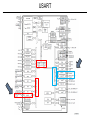
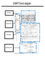
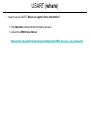
Laboratorio di Architetture e Programmazione dei Sistemi Elettronici Industriali Prof. Luca Benini <[email protected]> Simone Benatti <[email protected]> Filippo Casamassima<[email protected]> #1 USART USART • USART (Universal Synchronous-Asynchronous Receiver/Transmitter) The USART is the most used serial communication interface (eg. PC RS232 interface, IC communication interface, BT and WiFi module interface) FEATURES: FLAGS: ● Full duplex, asynchronous communications – Receive buffer full ● Fractional baud rate generator systems – Transmit buffer empty – End of Transmission flags ● Parity control: – Transmits parity bit – Checks parity of received data byte ● Four error detection flags: – Overrun error – Noise error – Frame error – Parity error ● Ten interrupt sources with flags: – CTS changes – Transmit data register empty – Transmission complete – Receive data register full – Idle line received – Overrun error – Framing error – Noise error – Parity error ● Multiprocessor communication - enter into mute mode if address match does not occur – A common programmable transmit and receive baud rates up to 4.5 MBits/s ● Programmable data word length (8 or 9 bits) ● Configurable stop bits - support for 1 or 2 stop bits ● Transmitter clock output for synchronous transmission ● Single wire half duplex communication ● Configurable multibuffer communication using DMA (direct memory access) – Buffering of received/transmitted bytes in reserved SRAM using centralized DMA ● Separate enable bits for Transmitter and Receiver USART USART Tx/Rx Transmitter The transmitter can send data words of either 8 or 9 bits depending on the M bit status. When the transmit enable bit (TE) is set, the data in the transmit shift register is output on the TX pin and the corresponding clock pulses are output on the CK pin. Character transmission During a USART transmission, data shifts out least significant bit first on the TX pin. In this mode, the USART_DR register consists of a buffer (TDR) between the internal bus and the transmit shift register Every character is preceded by a start bit which is a logic level low for one bit period. The character is terminated by a configurable number of stop bits. The following stop bits are supported by USART: 0.5, 1, 1.5 and 2 stop bits. Note: 1 The TE bit should not be reset during transmission of data. Resetting the TE bit during the transmission will corrupt the data on the TX pin as the baud rate counters will get frozen. The current data being transmitted will be lost. 2 An idle frame will be sent after the TE bit is enabled. Receiver The USART can receive data words of either 8 or 9 bits depending on the M bit in the USART_CR1 register. Character reception During a USART reception, data shifts in least significant bit first through the RX pin. In this mode, the USART_DR register consists of a buffer (RDR) between the internal bus and the received shift register. USART block diagram Data registers External interface Control registers Baud Rate generator USART registers Status register The USART interrupt events are connected to the Data register Baud Rate register Control register 1 Control register 2 Control register 3 Prescaler register same interrupt routine ● During transmission: Transmission Complete, Clear to Send or Transmit Data Register empty interrupt. ● While receiving: Idle Line detection, Overrun error, Receive Data register not empty, Parity error, LIN break detection, Noise Flag (only in multi buffer communication) and Framing Error (only in multi buffer communication). These events generate an interrupt if the corresponding Enable Control Bit is set. USART TX RX Procedure: Procedure: 1. Enable the USART by writing the UE bit in USART_CR1 register to 1. 2. Program the M bit in USART_CR1 to define the word length. 3. Program the number of stop bits in USART_CR2. 4. Select DMA enable (DMAT) in USART_CR3 if Multi buffer Communication is to take place. Configure the DMA register as explained in multibuffer communication. 5. Select the desired baud rate using the USART_BRR register. 6. Set the TE bit in USART_CR1 to send an idle frame as first transmission. 7. Write the data to send in the USART_DR register (this clears the TXE bit). Repeat this for each data to be transmitted in case of single buffer. 8. After writing the last data into the USART_DR register, wait until TC=1. This indicates that the transmission of the last frame is complete. This is required for instance when the USART is disabled or enters the Halt mode to avoid corrupting the last transmission. 1. Enable the USART by writing the UE bit in USART_CR1 register to 1. 2. Program the M bit in USART_CR1 to define the word length. 3. Program the number of stop bits in USART_CR2. 4. Select DMA enable (DMAR) in USART_CR3 if multibuffer communication is to take place. Configure the DMA register as explained in multibuffer communication. 5. Select the desired baud rate using the baud rate register USART_BRR 6. Set the RE bit USART_CR1. This enables the receiver which begins searching for a start bit Single byte communication Single byte communication The TXE bit is always cleared by a write to the data register. The TXE bit is set by hardware and it indicates: ● The data has been moved from TDR to the shift register and the data transmission has started. ● The TDR register is empty. ● The next data can be written in the USART_DR register without overwriting the previous data. This flag generates an interrupt if the TXEIE bit is set. ● The RXNE bit is set. It indicates that the content of the shift register is transferred to the RDR. In other words, data has been received and can be read (as well as its associated error flags). ● An interrupt is generated if the RXNEIE bit is set. ● The error flags can be set if a frame error, noise or an overrun error has been detected during reception. ● In multibuffer, RXNE is set after every byte received and is cleared by the DMA read to he Data Register. ● In single buffer mode, clearing the RXNE bit is performed by a software read to the USART_DR register. The RXNE flag can also be cleared by writing a zero to it. The RXNE bit must be USART (what) • I want to use an USART. What do I need to know? Which bus USARTx are connected to? ➡ Look at the architecture diagram Which port are we going to use? ➡ Look at the development board documentation What do I need to do with this USART? (input, output, ...) ➡ Configure for 38400 / 8 N 1 (google this if you want to know more about the configurations) USART (where) • I want to use an USART. Where can I gather these information? ➡ The datasheet contains all the information we need ➡ Look at the UM0919 User Manual https://www1.elfa.se/data1/wwwroot/assets/datasheets/STM32_discovery_eng_manual.pdf USART (code) main.c #include "stm32F10x.h" #include "STM32vldiscovery.h" //#include "stm32f10x_exti.h" #include "misc.h" #include "stm32f10x_gpio.h " #include "stm32f10x_usart.h" #include <stdio.h> typedef enum { FAILED = 0, PASSED = !FAILED} TestStatus; /* Private define ------------------------------------------------------------*/ #define RxBufferSize1 128 /* Private macro -------------------------------------------------------------*/ #define countof(a) (sizeof(a) / sizeof(*(a))) #define PUTCHAR_PROTOTYPE int fputc(int ch, FILE *f) /* Private variables ---------------------------------------------------------*/ uint8_t RxBuffer1[RxBufferSize1]; __IO uint8_t RxCounter1 = 0x00; uint8_t NbrOfDataToRead1 = RxBufferSize1; char c = 'r'; char received_ch; /* Private function prototypes -----------------------------------------------*/ void RCC_Configuration(void); void GPIO_Configuration(void); void NVIC_Configuration(void); void USART_Configuration(void); … Function and variables prototypes USART(code) /* Private functions ---------------------------------------------------------*/ void RCC_Configuration(void) { /* Enable GPIO clock */ RCC_APB2PeriphClockCmd(RCC_APB2Periph_GPIOA | RCC_APB2Periph_AFIO, ENABLE); RCC_APB2PeriphClockCmd(RCC_APB2Periph_USART1, ENABLE); } void GPIO_Configuration(void) { GPIO_InitTypeDef GPIO_InitStructure; /* Configure USARTy Rx as input floating */ GPIO_InitStructure.GPIO_Pin = GPIO_Pin_10; GPIO_InitStructure.GPIO_Mode = GPIO_Mode_IN_FLOATING; GPIO_Init(GPIOA, &GPIO_InitStructure); /* Configure USARTy Tx as alternate function push-pull */ GPIO_InitStructure.GPIO_Pin = GPIO_Pin_9; GPIO_InitStructure.GPIO_Speed = GPIO_Speed_50MHz; GPIO_InitStructure.GPIO_Mode = GPIO_Mode_AF_PP; GPIO_Init(GPIOA, &GPIO_InitStructure); } void NVIC_Configuration(void) { NVIC_InitTypeDef NVIC_InitStructure; /* Configure the NVIC Preemption Priority Bits */ NVIC_PriorityGroupConfig(NVIC_PriorityGroup_0); /* Enable the USARTy Interrupt */ NVIC_InitStructure.NVIC_IRQChannel = USART1_IRQn; NVIC_InitStructure.NVIC_IRQChannelSubPriority = 0; NVIC_InitStructure.NVIC_IRQChannelCmd = ENABLE; NVIC_Init(&NVIC_InitStructure); } … INIT functions USART (code) void USART_Configuration(void) { USART_InitTypeDef USART_InitStructure; USART_InitStructure.USART_BaudRate = 9600; USART_InitStructure.USART_WordLength = USART_WordLength_8b; USART_InitStructure.USART_StopBits = USART_StopBits_1; USART_InitStructure.USART_Parity = USART_Parity_No; USART_InitStructure.USART_HardwareFlowControl = USART_HardwareFlowControl_None; USART_InitStructure.USART_Mode = USART_Mode_Rx | USART_Mode_Tx; /* Configure USARTy */ USART_Init(USART1, &USART_InitStructure); /* Enable USARTy Receive and Transmit interrupts */ //USART_ITConfig(USART1, USART_IT_RXNE, ENABLE); //USART_ITConfig(USART1, USART_IT_TXE, ENABLE); Interrupt enable (use in later exercise) /* Enable the USARTy */ USART_Cmd(USART1, ENABLE); } int main(void) { RCC_Configuration(); NVIC_Configuration(); GPIO_Configuration(); USART_Configuration(); USART_SendData(USART1,c); Sending the character while(USART_GetFlagStatus(USART1,USART_FLAG_TC) == RESET); while (1) { if (USART_GetFlagStatus(USART1 , USART_FLAG_RXNE) != RESET) { received_ch = USART_ReceiveData(USART1); received_ch = received_ch; } } } Receiving the character USART (code) stm32f10x_it.c … void USART1_IRQHandler(void) { if(USART_GetITStatus(USART1, USART_IT_TXE) == SET) { //write interrupt code here //Remember to disable the transmission after the tx of last char } if(USART_GetITStatus(USART1, USART_IT_RXNE) != RESET) { /* Read one byte from the receive data register */ // use the function USART receive data USART_ReceiveData(USART1); } USART (exercises) Exercise 1 • Verify the TX and the RX of the char ‘r’ in the USART1 of the board, by a shortcircuit between the RX and TX pin. (Check the docs to decide which pins should be connected toghether) Exercise 2 • Repeat exercise 1 using the interrupt TX and RX routine (Hint: use the debugger and breakpoints) (Hint 2: implement the two interrupt separately to verify your solution) Exercise 3 • Repeat exercise 1 and 2 with TX and RX of the string “#yourname” instead of the byte ‘r’ (Hint: try the function “sprint” for a compact solution or use a for/while loop). Exercise 4 • Connect two board. Send a value from board 1 to board 2. After 3 second resend the (value+1) from board 2 to board 1. After 3 second restart with (value + 2)…etc…