1
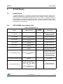
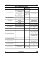
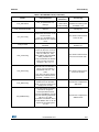
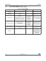
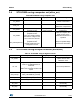
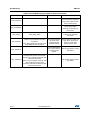
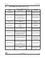
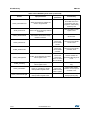
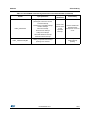
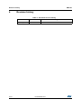
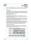
UM1753 User manual Description of STLUX385A peripheral library Introduction This user manual provides complete information for SW developers on the STLUX385A library, a library of APIs useful to get familiar developing applications for the STLUX385A digital controller and its peripherals. The STLUX385A is an STMicroelectronics® digital device tailored for lighting applications. The heart of the STLUX is the SMED (“State Machine Event Driven”) technology which allows the device to operate several independently configurable PWM clocks with up to 1.3 ns resolution. A SMED is a powerful autonomous state machine which is programmed to react to both external and internal events and may evolve without any software intervention. The tools provided by this Kit will help you understand the SMEDs and how to program them in your applications. SMEDs are configured and programmed via the STLUX internal low-power microcontroller (STM8). This manual describes the tools provided in this kit. May 2014 DocID026248 Rev 1 1/21 www.st.com Contents UM1753 Contents 1 Reference documents . . . . . . . . . . . . . . . . . . . . . . . . . . . . . . . . . . . . . . . . 4 2 Acronyms . . . . . . . . . . . . . . . . . . . . . . . . . . . . . . . . . . . . . . . . . . . . . . . . . . 5 3 STLUX library . . . . . . . . . . . . . . . . . . . . . . . . . . . . . . . . . . . . . . . . . . . . . . . 7 4 2/21 3.1 Introduction . . . . . . . . . . . . . . . . . . . . . . . . . . . . . . . . . . . . . . . . . . . . . . . . 7 3.2 STLUX385A clock (stlux_clk) . . . . . . . . . . . . . . . . . . . . . . . . . . . . . . . . . . . 7 3.3 STLUX385A SMEDs (stlux_smed) . . . . . . . . . . . . . . . . . . . . . . . . . . . . . . 10 3.4 STLUX385A analog comparator unit (stlux_acu) . . . . . . . . . . . . . . . . . . . .11 3.5 STLUX385A analog-to-digital converter (stlux_adc) . . . . . . . . . . . . . . . . .11 3.6 STLUX385A system timer (stlux_stmr) . . . . . . . . . . . . . . . . . . . . . . . . . . 13 3.7 STLUX385A general purpose I/O (stlux_gpio) . . . . . . . . . . . . . . . . . . . . . 15 3.8 STLUX385A auxiliary timer (stlux_atm) . . . . . . . . . . . . . . . . . . . . . . . . . . 16 3.9 STLUX385A auto wake-up unit (stlux_awu) . . . . . . . . . . . . . . . . . . . . . . . 16 3.10 STLUX385A universal asynchronous receiver/transmitter (stlux_uart) . . 17 Revision history . . . . . . . . . . . . . . . . . . . . . . . . . . . . . . . . . . . . . . . . . . . 20 DocID026248 Rev 1 UM1753 List of tables List of tables Table 1. Table 2. Table 3. Table 4. Table 5. Table 6. Table 7. Table 8. Table 9. Table 10. Table 11. List of acronyms . . . . . . . . . . . . . . . . . . . . . . . . . . . . . . . . . . . . . . . . . . . . . . . . . . . . . . . . . . 5 STLUX385A clock. . . . . . . . . . . . . . . . . . . . . . . . . . . . . . . . . . . . . . . . . . . . . . . . . . . . . . . . . 7 STLUX385A SMEDs. . . . . . . . . . . . . . . . . . . . . . . . . . . . . . . . . . . . . . . . . . . . . . . . . . . . . . 10 STLUX385A analog comparator unit . . . . . . . . . . . . . . . . . . . . . . . . . . . . . . . . . . . . . . . . . 11 STLUX385A analog-to-digital converter . . . . . . . . . . . . . . . . . . . . . . . . . . . . . . . . . . . . . . . 11 STLUX385A system timer . . . . . . . . . . . . . . . . . . . . . . . . . . . . . . . . . . . . . . . . . . . . . . . . . 13 STLUX385A general purpose I/O . . . . . . . . . . . . . . . . . . . . . . . . . . . . . . . . . . . . . . . . . . . . 15 STLUX385A auxiliary timer. . . . . . . . . . . . . . . . . . . . . . . . . . . . . . . . . . . . . . . . . . . . . . . . . 16 STLUX385A auto wake-up unit . . . . . . . . . . . . . . . . . . . . . . . . . . . . . . . . . . . . . . . . . . . . . 16 STLUX385A universal asynchronous receiver/transmitter . . . . . . . . . . . . . . . . . . . . . . . . . 17 Document revision history . . . . . . . . . . . . . . . . . . . . . . . . . . . . . . . . . . . . . . . . . . . . . . . . . 20 DocID026248 Rev 1 3/21 21 Reference documents 1 4/21 UM1753 Reference documents For hardware information on the STLUX385A controller and product specific SMED configuration, please refer to the STLUX385A product datasheet. For information on programming, erasing and protection of the internal Flash memory please refer to the STM8 Flash programming manual (PM0047). For information about the debug and SWIM (single-wire interface module) refer to the STM8 SWIM communication protocol and debug module user manual (UM0470). For information on the STM8 core and assembler instruction please refer to the STM8 CPU programming manual (PM0044). For information on the SMED configurator please refer to the UM1760 “STLUX™ SMED configurator 1.0” user manual. DocID026248 Rev 1 UM1753 2 Acronyms Acronyms A list of acronyms used in this document: Table 1. List of acronyms Acronym Description ACU Analog comparator unit ADC Analog-to-digital converter ATM Auxiliary timer AWU Auto wake-up unit BL Bootloader - used to load the user program without the emulator CCO Configurable clock output CKC Clock control unit CKM Clock master CPU Central processing unit CSS Clock security system DAC Digital-to-analog converter DALI Digital addressable lighting interface ECC Error Correction Code FSM Finite state machine FW Firmware loaded and running on the CPU GPIO General purpose input output HSE High-speed external crystal - ceramic resonator HSI High-speed internal RC oscillator I2C Inter-integrated circuit interface IAP In-application programming ICP In-circuit programming ITC Interrupt controller IWDG Independent watchdog LSI Low-speed Internal RC oscillator MCU Microprocessor central unit MSC Miscellaneous PM Power management RFU Reserved for future use ROP Read-out protection RST Reset control unit RTC Real-time clock DocID026248 Rev 1 5/21 21 Acronyms UM1753 Table 1. List of acronyms (continued) 6/21 Acronym Description SMED State machine event driven STMR System timer SW Software, is the firmware loaded and running on the CPU (synonymous of FW) SWI Clock switch interrupt SWIM Single-wire interface module UART Universal asynchronous receiver/transmitter WWDG Window watchdog DocID026248 Rev 1 UM1753 STLUX library 3 STLUX library 3.1 Introduction The STLUX385A library is a collection of APIs aiming to simplify the usage of the STLUX SMEDs and peripherals to application developers. Each collection of APIs is dedicated to a specific device or functionality and named so “stlux_xxx” where “xxx” stands for the name of the peripheral. The library is developed using the C language compatible with the IAR™ and Raisonance tools and is composed of the “stlux_xxx.c” and “stlux_xxx.h” relative files to be included in your application. 3.2 STLUX385A clock (stlux_clk) Table 2. STLUX385A clock Header Input parameters Output parameters Functionality Sets the clock internal registers to their default initialization values. CLK_Reset CLK_HSECmd NewState: it can be ENABLE or DISABLE. Enables/disables HSE. CLK_HSICmd NewState: it can be ENABLE or DISABLE. Enables/disables HSI. CLK_LSICmd NewState: it can be ENABLE or DISABLE. Enables/disables LSI. CLK_CCOCmd NewState: it can be ENABLE or DISABLE. Enables/disables CCO. CLK_ClockSwitchCmd NewState: it can be ENABLE or DISABLE. Manually starts/stops the clock switch execution. CLK_FastHaltWakeUpCmd NewState: it can be ENABLE or DISABLE. When enabled, the HSI oscillator is automatically switched-on and selected as a next master clock when resuming from HALT/active-halt modes. CLK_SlowActiveHaltWakeUpCmd NewState can be ENABLE or DISABLE. Configures the slow activehalt wakeup. CLK_PeripheralClockConfig CLK_Peripheral can be one of the following peripherals: I2C, GPIO0, UART, DALI, STMR, GPIO1, AWU, ADC, SMEDx, MSC. NewState can be ENABLE or DISABLE. Enables/disables the specified peripheral CLK. DocID026248 Rev 1 7/21 21 STLUX library UM1753 Table 2. STLUX385A clock (continued) Output parameters Header Input parameters Functionality CLK_ClockSwitchConfig CLK_SwitchMode: the clock switch mode can be MANUAL or AUTOMATIC. CLK_NewClock: the new clock source can be HSI/LSI/HSE. ITState can be ENABLE or DISABLE. CLK_CurrentClockState can be ENABLE or DISABLE. ErrorStatus reports ERROR This function configures the or SUCCESS clock switch from a clock according to the source to another. operation result. CLK_HSIPrescalerConfig HSIPrescaler specifies the HIS/CPU clock divider to apply. This function configures the HSI or CPU clock dividers. CLK_ITConfig CLK_IT specifies the interrupt sources. They can be the CSS or the SWI. NewState can be ENABLE or DISABLE. This function enables/disables the specified CLK interrupts. CLK_SYSCLKConfig CLK_Prescaler specifies the HIS/CPU clock divider to apply. This function configures the HSI or CPU clock dividers. CLK_SWIMConfig CLK_SWIMDivider specifies the SWIM clock divider to apply. It can be divided by 1 or 2. This function configures the SWIM clock frequency on the fly. CLK_ClockSecuritySystemEnable This function enables the CSS. CLK_SYSCLKEmergencyClear This function reset SWBSY flag in order to reset clock switch operations (target oscillator is broken, stabilization is longing too much, etc.). If at the same time software attempts to set SWEN and clear SWBSY, SWBSY action takes precedence. CLK_AdjustHSICalibrationValue This function adjusts the HSI calibration value. CLK_GetClockFreq This function returns the frequency of the currently used on chip clock. CLK_GetSYSCLKSource Returns the clock source currently used as system clock. CLK_GetFlagStatus 8/21 CLK_HSICalibrationValue is the calibration trimming value. CLK_FLAG is the clock status flag to be checked. DocID026248 Rev 1 FlagStatus is the current flag status value. Checks whether the specified CLK flag is set or not. UM1753 STLUX library Table 2. STLUX385A clock (continued) Output parameters Header Input parameters CLK_GetITStatus CLK_IT specifies the CLK interrupt. ITStatus is the Checks whether the current status specified CLK interrupt has for the interrupt. is enabled or not. CLK_ClearITPendingBit CLK_IT specifies the CLK interrupt. Clears the CLK's interrupt pending bits. CLK_PLLConfig CLK_PLL_Source specifies the clock source for the PLL. It can be HSI or HSE. CLK_PLL_DIVPRES is the division factor for PLL selected clock. This function sets the clock source for PLL. CLK_PLLCmd NewState can be ENABLE or DISABLE. This function enables or disables PLL. CLK_CCOConfig CLK_CCO specifies the clock source for the CCO. It can be one of the following sources: HIS, LSI, HSE, PLL, CPU, CKM, SMEDx, ADC, EEPROM, AWU, prescaled PLL. CLK_CCODIVR is the division factor n for the CCO clock, CLKCCO = CLK / (n + 1). This function sets the clock source for the CCO clock. CLK_ADCConfig CLK_ADC_Source specifies the clock source for the ADC. It can be one of the following peripherals: HSI, PLL, LSI, HSE. CLK_ADC_DIV is the division factor for PLL selected clock. CLKADC = CLKSEL / (n+1). This function sets the clock source for the ADC. CLK_AWUConfig CLK_AWU_DIVIDER is the division factor for the AWU clock. It can be a power of two ranging from 1 to 256. This function configures the AWU clock. CLK_SMEDConfig CLK_SMD selects the SMEDx clock to be configured. Source specifies the clock source for the SMEDx. It can be one of the following peripherals: HSI, PLL, LSI, HSE. Prescaler is the division factor for the SMEDx clock. It can be a power of two ranging from 1 to 128. This function configures the SMEDS clock. DocID026248 Rev 1 Functionality 9/21 21 STLUX library 3.3 UM1753 STLUX385A SMEDs (stlux_smed) Table 3. STLUX385A SMEDs Header Input parameters Output parameters Functionality SMED_Start SMEDx is the SMED to be started. This function makes the SMEDx start running. SMED_Stop SMEDx is the SMED to be stopped. This function makes the SMEDx stop running. SMED_SetTime SMEDx is the SMED which time It returns zero in case must be set. of unsuccessful TimeRegister is the status for which operation due to the time must be set. The status pending time can be T0, T1, T2 or T3. validation, one otherwise. Value is the time value to be set. Sets the time value to the status TimeRegister for the selected SMEDx. SMED_ValidateTimeValues It returns zero in case of unsuccessful SMEDx is the SMED. operation due to TimeVal is the timer (or the timers) pending time to be validated. validation, one otherwise. Validates the settings previously set with SMED_SetTime for the desired SMEDx timers. SMED_TrigSWEvent X can assume values ranging from 0 to 7 and corresponds to the SW event trigger. This function is defined as void function by default and can be manually generated or by using the SMED configurator. SMED_Init 10/21 This function enables the SW event triggers for the SMED FSM. DocID026248 Rev 1 UM1753 3.4 STLUX library STLUX385A analog comparator unit (stlux_acu) Table 4. STLUX385A analog comparator unit Header Input parameters Output parameters Functionality ACU_Reset Sets the ACU internal registers to their default initialization values. ACU_Init Enables the ACU unit and initializes the compare levels. ACU_Read ACUx specifies the comparator peripheral number. ACU_Enable ACUx specifies the comparator peripheral number. CP3_SEL specifies whether the reference voltage for the CP3 is internal or external. Enables the comparator CPx. In case of CP3, also the internal/external reference is specified. ACUx specifies the comparator peripheral number. ACU_SetCompareLevel DACIN specifies the input voltage level to be set. Assigns a specified voltage level reference to the DACx. 3.5 The comparator output value is returned. Reads the output of the comparator x. STLUX385A analog-to-digital converter (stlux_adc) Table 5. STLUX385A analog-to-digital converter Header Input parameters Output parameters Functionality Sets the ADC internal registers to their default initialization values. ADC_Reset ADC_Init ADC_ConvMode_Init is the conversion mode. It can be SEQUENCE or CIRCULAR. ADC_DataFormat_Init determines whether the 10 bits data are left or right aligned. ADC_Interrupt ADC_IntEndConvMode_Interrupt. ADC_IntEndSeqMode_interrupt ADC_IntSeqFull_Interrupt ADC_Sequencer ADC_Channel_Sequencer This function initializes the ADC sequencer. ADC_Gain_Sequencer ADC_Start This function enables ADC functionality. ADC_Stop This function disables ADC functionality. DocID026248 Rev 1 11/21 21 STLUX library UM1753 Table 5. STLUX385A analog-to-digital converter (continued) Header Input parameters Output parameters Functionality ADC_PowerUp This function performs the correct power-on sequence for the ADC (after a power down to save power). ADC_PowerDown This function performs the correct power-down sequence for the ADC (to save power). ADC_Delay ADC_Delay_Value ADC_Measure ADC_Channel_Measure is the channel number to be activated for the data acquisition. ADC_Gain_Measure is the gain factor to be applied for the conversion. ADC_GetStatus ADC_SetStatus 12/21 This function introduces a delay in the following conversion. This function returns the 16-bit value coming from the specified channel. Given a channel number and a gain factor, the function returns a 16-bit value captured by the ADC. The returned data is the current value of the ADC status register. This function gets the current ADC status. EOS: end of sequence mode bit.HW sets this bit at the end of conversion sequence and must be cleared by SW. This bit is white-clear. EOC: end of conversion mode bit. HW sets this bit at the end of each conversion and must be cleared by SW. This bit is white-clear. DocID026248 Rev 1 This function sets the current ADC status. UM1753 3.6 STLUX library STLUX385A system timer (stlux_stmr) Table 6. STLUX385A system timer Header Input parameters Output parameters Functionality Sets the STMR internal registers to their default initialization values. STMR_Reset STMR_TimeBaseInit STMR_Prescaler specifies the prescaler division factor for the STMR. It can be a power of two ranging from 1 to 128. STMR_Period specifies the period to be set for the timer interrupt generation. Initializes the STMR time base unit according to the specified parameters. STMR_Cmd NewState: it can be ENABLE or DISABLE. This function enables or disables the STMR peripheral. STMR_ITConfig STMR_IT specifies whether the STMR interrupt must be enabled or disabled. NewState can be ENABLE or DISABLE. Enables or disables the specified STMR interrupts. STMR_UpdateDisableConfig Newstate can be ENABLE or DISABLE. Enables or disables the update event for the autoreload preload mode. STMR_UpdateSource specifies whether the interrupt is generated by counter overflow only or by registers STMR_UpdateRequestConfig update. Possible values are UPDATESOURCE_GLOBAL and UPDATESOURCE_REGULAR. Selects the STMR Update Request Interrupt source. STMR_SelectOnePulseMode STMR_OPMode specifies if the one pulse mode must be activated. Enables or disables the one pulse. This mode makes the counter stop when the next update event is triggered. STMR_PrescalerConfig Prescaler specifies the prescaler division factor for the STMR. It can be a power of two ranging from 1 to 128. STMR_PSCReloadMode specifies whether the prescaler is loaded immediately or at the update event. This function configures the STMR prescaler. STMR_ARRPreloadConfig Newstate can be ENABLE or DISABLE. Enables or disables STMR peripheral on autoreload preload enable register. DocID026248 Rev 1 13/21 21 STLUX library UM1753 Table 6. STLUX385A system timer (continued) Header Input parameters Output parameters Functionality STMR_GenerateEvent STMR_EventSource enables the event to be generated. This function configures the STMR event to be generated by SW. The register is automatically cleared by HW. STMR_SetCounter Counter specifies the counter new value to be set in the range 0x0000 to 0xFFFF. Sets the STMR counter register value. STMR_SetAutoreload Auto-reload specifies the auto-reload new value to be set in the range 0x0000 to 0xFFFF. Sets the STMR autoreload value. STMR_GetCounter The returned value is the current STMR counter. Gets the current STMR counter value. STMR_GetPrescaler The returned value is the current STMR prescaler. Gets the current STMR prescaler value. STMR_GetFlagStatus STMR_FLAG specifies the STMR status register value. The returned value is the Checks whether the current flag specified STMR flag is set status. It can be or not. SET or RESET. STMR_ClearFlag STMR_FLAG specifies the STMR status register value. Clears the STMR status flag. STMR_GetITStatus STMR_IT specifies the STMR interrupt status register value. STMR_ClearITPendingBit STMR_IT specifies the STMR interrupt status register value. 14/21 DocID026248 Rev 1 The returned value is the STMR interrupt status register. This function checks whether an interrupt has occurred or not. This function clear the interrupt pending flag. UM1753 3.7 STLUX library STLUX385A general purpose I/O (stlux_gpio) Table 7. STLUX385A general purpose I/O Output parameters Header Input parameters GPIO_Reset GPIOx specifies the GPIO peripheral number. Sets the GPIOx internal registers to their default initialization values. GPIO_Init GPIOx specifies the GPIO peripheral number. GPIO_Pin specifies the pins to be associated to the I/O. GPIO_Mode specifies one of the possible GPIO configurations. Initializes the GPIOx according to the specified parameters. GPIO_Write GPIOx specifies the GPIO peripheral number. PortVal specifies the value to be written to the port output. Writes data to the specified GPIO data port. GPIO_WriteHigh GPIOx specifies the GPIO peripheral number. PortPins specifies the pins to be turned high to the port output Sets high level to the specified GPIO pins. GPIO_WriteLow GPIOx specifies the GPIO peripheral number. PortPins specifies the pins to be turned low to the port output. Sets low level to the specified GPIO pins. GPIO_WriteReverse GPIOx specifies the GPIO peripheral number. PortPins specifies the pins to be reversed to the port output. Writes reverse level to the specified GPIO pins. GPIO_ReadInputData GPIOx specifies the GPIO peripheral number This function returns the read value. Reads the specified GPIO input data port. GPIO_ReadOutputData GPIOx specifies the GPIO peripheral number. This function returns the read value. Reads the specified GPIO output data port. GPIO_ReadInputPin GPIOx specifies the GPIO peripheral number. GPIO_Pin specifies the pins to be read BitStatus Reads the specified GPIO input data pin. GPIO_ExternalPullUpConfig GPIOx specifies the GPIO peripheral number. GPIO_Pin specifies the pins to be configured. Newstate is the new state of the pull-up pins. It can be ENABLE or DISABLE. DocID026248 Rev 1 Functionality Configures the external pull-up on GPIOx pins. 15/21 21 STLUX library 3.8 UM1753 STLUX385A auxiliary timer (stlux_atm) Table 8. STLUX385A auxiliary timer Header Output parameters Input parameters Functionality Sets the ATM internal registers to their default initialization values. ATM_Reset ATM_Config CLK_CCO specifies the selected clock source for the CCO derived clock. CLK_CCODIVR specifies the frequency division factor for the CCO derived clock. IT_LEV specifies the interrupt level sensitivity (high/low) for the ATM. IT_SEL specifies the interrupt trigger (source/edge) for the ATM. IT_TYPE specifies the interrupt Type (IRQ/NMI/Polling) for the ATM. Sets the ATM registers to the desired configuration. ATM_OutDigIn0 NewState can be ENABLE or DISABLE. Enables or disables the ATM clock to be sent to DIGIN(0). ATM_ITConfig NewState can be ENABLE or DISABLE. Enables or disables the ATM to generate interrupt. 3.9 STLUX385A auto wake-up unit (stlux_awu) Table 9. STLUX385A auto wake-up unit Header Input parameters Output parameters Functionality Sets the AWU internal registers to their default initialization values. AWU_Reset AWU_Init AWU_Prescaler specifies the number of steps to be counted between two AWU interrupts. It must be a value ranging from 0 to 62. AWU_TimeBase specifies the value of a single step. Initializes the AWU peripheral according to the specified parameters. AWU_Enable NewState can be ENABLE or DISABLE. Enables or disables the AWU peripheral. Configures AWU in Idle mode to reduce power consumption. AWU_IdleModeEnable AWU_GetStatus 16/21 Returns status of the Checks the status flag of the AWU peripheral flag. AWU peripheral. DocID026248 Rev 1 UM1753 3.10 STLUX library STLUX385A universal asynchronous receiver/transmitter (stlux_uart) Table 10. STLUX385A universal asynchronous receiver/transmitter Header Input parameters Output parameters Functionality Sets the UART internal registers to their default initialization values. UART_Reset UART_Init BaudRate specifies the baud rate. It can be up to f_clk/16. WordLength is the data wordlength, it can be 8 or 9 bits. StopBits specifies the stop bits sequence to be used. Parity specifies if even, odd or no parity must be used. PIN specifies the UART pin configuration. Mode specifies the Rx/Tx configuration. Initializes the AWU peripheral according to the specified parameters. UART_Cmd NewState can be ENABLE or DISABLE. Enables or disables the UART peripheral. UART_ITConfig UART_IT specifies the interrupt source to be enabled. NewState can be ENABLE or DISABLE. Enables or disables the specific UART interrupts. UART_IsITEnabled UART_IT specifies the interrupt source to be checked. UART_HalfDuplexCmd NewState can be ENABLE or DISABLE. Enables or disables the UART's half duplex communication. UART_LINBreakDetectionConfig UART_LINBreakDetectionLength specifies whether the LIN break detection length is 10 or 11 bits. Sets the UART line break detection length. UART_LINCmd NewState can be ENABLE or DISABLE. Enables or disables the UART's line break detection. UART_WakeUpConfig UART_WakeUp specifies the UART wake-up method to be used. Selects the UART wake-up method. UART_ReceiverWakeUpCmd NewState can be ENABLE or DISABLE. Determines if the UART is in mute mode or not. DocID026248 Rev 1 Gets a positive value if true, zero otherwise. Checks whether a specific UART interrupt source is enabled. 17/21 21 STLUX library UM1753 Table 10. STLUX385A universal asynchronous receiver/transmitter (continued) Output parameters Functionality UART_ReceiveData8 The returned value is the most recent 8-bit data. Returns the most recent received data by the UART peripheral. UART_ReceiveData9 The returned value is the most recent 9-bit data. Returns the most recent received data by the UART peripheral. Header Input parameters UART_SendData8 Data is the 8-bit data to be transmitted. Transmits 8-bit data through the UART peripheral. UART_SendData9 Data is the 9-bit data to be transmitted. Transmits 9-bit data through the UART peripheral. Transmits break characters. UART_SendBreak 18/21 UART_SetAddress UART_Address specifies the address for the UART node. Sets the address of the UART node. UART_SetPrescaler Prescaler can be a value ranging from 0 to 128. Sets the system clock UART prescaler. UART_GetFlagStatus UART_FLAG specifies the UART status flag to be checked. It can be: Transmit data register empty flag Transmission complete flag Read data register not empty flag Idle line detected flag Overrun error flag Noise error flag Framing error flag Parity error flag Line break detection flag Send break characters flag UART_ClearFlag UART_FLAG specifies the UART status flag to be cleared. DocID026248 Rev 1 Returns the current status for the specified flag. Checks whether the specified UART flag is set or not. Clears the specified UART flag. UM1753 STLUX library Table 10. STLUX385A universal asynchronous receiver/transmitter (continued) Header Input parameters Output parameters Functionality UART_GetITStatus UART_IT specifies the UART interrupt pending bit to check. It can be: Transmit interrupt Transmission complete interrupt Receive interrupt IDLE line interrupt Overrun error interrupt Parity error interrupt LIN break detection interrupt Receive/overrun interrupt Returns the current status for the specified interrupt. Checks whether the specified UART interrupt has occurred or not. UART_ClearITPendingBit UART_IT specifies the interrupt pending to be cleared. DocID026248 Rev 1 Clears a specified UART interrupt pending. 19/21 21 Revision history 4 UM1753 Revision history Table 11. Document revision history 20/21 Date Revision 14-May-2014 1 Changes Initial release. DocID026248 Rev 1 UM1753 Please Read Carefully: Information in this document is provided solely in connection with ST products. STMicroelectronics NV and its subsidiaries (“ST”) reserve the right to make changes, corrections, modifications or improvements, to this document, and the products and services described herein at any time, without notice. All ST products are sold pursuant to ST’s terms and conditions of sale. Purchasers are solely responsible for the choice, selection and use of the ST products and services described herein, and ST assumes no liability whatsoever relating to the choice, selection or use of the ST products and services described herein. No license, express or implied, by estoppel or otherwise, to any intellectual property rights is granted under this document. If any part of this document refers to any third party products or services it shall not be deemed a license grant by ST for the use of such third party products or services, or any intellectual property contained therein or considered as a warranty covering the use in any manner whatsoever of such third party products or services or any intellectual property contained therein. UNLESS OTHERWISE SET FORTH IN ST’S TERMS AND CONDITIONS OF SALE ST DISCLAIMS ANY EXPRESS OR IMPLIED WARRANTY WITH RESPECT TO THE USE AND/OR SALE OF ST PRODUCTS INCLUDING WITHOUT LIMITATION IMPLIED WARRANTIES OF MERCHANTABILITY, FITNESS FOR A PARTICULAR PURPOSE (AND THEIR EQUIVALENTS UNDER THE LAWS OF ANY JURISDICTION), OR INFRINGEMENT OF ANY PATENT, COPYRIGHT OR OTHER INTELLECTUAL PROPERTY RIGHT. ST PRODUCTS ARE NOT DESIGNED OR AUTHORIZED FOR USE IN: (A) SAFETY CRITICAL APPLICATIONS SUCH AS LIFE SUPPORTING, ACTIVE IMPLANTED DEVICES OR SYSTEMS WITH PRODUCT FUNCTIONAL SAFETY REQUIREMENTS; (B) AERONAUTIC APPLICATIONS; (C) AUTOMOTIVE APPLICATIONS OR ENVIRONMENTS, AND/OR (D) AEROSPACE APPLICATIONS OR ENVIRONMENTS. WHERE ST PRODUCTS ARE NOT DESIGNED FOR SUCH USE, THE PURCHASER SHALL USE PRODUCTS AT PURCHASER’S SOLE RISK, EVEN IF ST HAS BEEN INFORMED IN WRITING OF SUCH USAGE, UNLESS A PRODUCT IS EXPRESSLY DESIGNATED BY ST AS BEING INTENDED FOR “AUTOMOTIVE, AUTOMOTIVE SAFETY OR MEDICAL” INDUSTRY DOMAINS ACCORDING TO ST PRODUCT DESIGN SPECIFICATIONS. PRODUCTS FORMALLY ESCC, QML OR JAN QUALIFIED ARE DEEMED SUITABLE FOR USE IN AEROSPACE BY THE CORRESPONDING GOVERNMENTAL AGENCY. Resale of ST products with provisions different from the statements and/or technical features set forth in this document shall immediately void any warranty granted by ST for the ST product or service described herein and shall not create or extend in any manner whatsoever, any liability of ST. ST and the ST logo are trademarks or registered trademarks of ST in various countries. Information in this document supersedes and replaces all information previously supplied. The ST logo is a registered trademark of STMicroelectronics. All other names are the property of their respective owners. © 2014 STMicroelectronics - All rights reserved STMicroelectronics group of companies Australia - Belgium - Brazil - Canada - China - Czech Republic - Finland - France - Germany - Hong Kong - India - Israel - Italy - Japan Malaysia - Malta - Morocco - Philippines - Singapore - Spain - Sweden - Switzerland - United Kingdom - United States of America www.st.com DocID026248 Rev 1 21/21 21