1
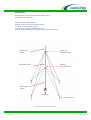
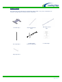
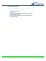
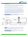
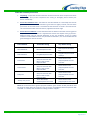
9m Guyed Tower for LE300 or LE600
Installation & Operation Guide
Tel: +44 (0)845 652 0396
Skyrrid Farm, Pontrilas, Hereford. HR2 0BW. UK
www.leturbines.com
Page 1 of 17
Contents
Disclaimer .......................................................................................................... 3
Introduction....................................................................................................... 4
Safety Precautions ............................................................................................. 5
Mechanical Safety Hazards ............................................................................. 5
Electrical Safety Hazards ................................................................................. 5
Specifications ..................................................................................................... 6
Tools Required For Assembly ............................................................................. 8
Turbine Site Selection ........................................................................................ 9
Tower Kit Assembly Procedure .......................................................................... 10
Maintenance..................................................................................................... 16
Spares ............................................................................................................... 16
Warranty .......................................................................................................... 17
Tel: +44 (0)845 652 0396
Skyrrid Farm, Pontrilas, Hereford. HR2 0BW. UK
www.leturbines.com
Page 2 of 17
Disclaimer
•
•
•
•
•
All specifications are subject to change without prior notice.
The information given in this user manual is believed to be accurate and reliable. Leading
Edge Turbines Ltd assumes no responsibility for omissions or inaccuracies.
The user of this information and product assumes full responsibility and risk.
Wind Turbines are a source of electrical power. They must be installed in accordance with
local building and electrical regulations. Consult your local planning (zoning) office for
details.
Wind turbines and associated equipment have moving parts that may cause injury due to
poor installation and unsafe operation. Leading Edge Turbines Ltd assumes no
responsibility for problems caused by unsafe or unsatisfactory installation or operation.
Designed & Manufactured in the UK By:
Leading Edge Turbines Ltd
Skyrrid Farm,
Pontrilas,
Hereford.
HR2 0BW
Tel: +44 (0)845 652 0396
www.leturbines.com
Tel: +44 (0)845 652 0396
Skyrrid Farm, Pontrilas, Hereford. HR2 0BW. UK
www.leturbines.com
Page 3 of 17
Introduction
Please read this manual thoroughly before attempting to assemble and install your Guyed Tower
Kit. This will assure optimum performance and safety.
This Tower Kit has been designed for use with the LE300 or LE600 Turbine from Leading Edge
Turbines Ltd. It is possible to use this kit with other turbines that require a 48.3mm diameter tower,
however under no circumstances should a turbine with a rotor diameter greater than 1.4m be
installed using this Tower. An adaptor can be supplied by Leading Edge Turbines to allow the fitting
of the LE600 turbine to this 48.3mm tower top.
It is possible to install the Guyed Tower, with two or three people, in a very short time. No winches
or gin-poles are necessary although may prove useful with the heavier LE600 turbine. Concrete may
be required depending on soil conditions.
Please read this manual carefully before continuing with the installation of your Guyed Tower.
Please read the LE300 or LE600 Installation and Operation Guide carefully before operating the
turbine.
Tel: +44 (0)845 652 0396
Skyrrid Farm, Pontrilas, Hereford. HR2 0BW. UK
www.leturbines.com
Page 4 of 17
Safety Precautions
Safety must always be your primary concern during the assembly, installation and operation of your
Guyed Tower. Always be aware of the risks involved with mechanical and electrical installation
work. If in doubt about any issue regarding your tower kit or turbine, please seek further assistance
before proceeding.
Mechanical Safety Hazards
•
•
•
•
•
•
•
•
•
•
•
•
Ensure that the tower and turbine are installed in a suitable position where nobody can
approach or interfere with the path of the turbine rotor blades.
Ensure that the tower is located in a position where it cannot cause any damage to
buildings, neighbours’ property or utility lines should the tower fall for any reason.
Never attempt to climb the tower. It is not designed to handle this type of loading and may
fail.
If at any time a component of the tower or turbine works loose, correct it immediately.
Working with tools of any kind can be dangerous. Your tower and turbine require some
basic mechanical assembly with rudimentary hand tools. If you are in any doubt about how
to use these tools correctly, please seek advice from a suitably experienced person.
Always ensure that all personnel in the immediate vicinity are aware of any lifting /
hoisting operations that will be occurring. Check there are no loose components or tools
likely to fall and cause injury during the lifting operation. Where possible, all assembly
work should be completed at ground level.
Ensure that any system batteries are disconnected during the installation procedure.
Use a run / stop switch to make the turbine safe before raising the tower.
Install your turbine and tower kit during a calm day.
When performing routine inspection or maintenance, always stop the turbine by activating
a run / stop switch.
Ensure protective gloves are worn when handling the guy wires.
Tower sections can be heavy, ensure protective footwear is used.
Electrical Safety Hazards
•
Always refer to the LE300 or LE600 Installation and Operation Guide for advice and
instructions on electrical aspects of the turbine installation
Please use common sense when installing and operating your turbine!
Tel: +44 (0)845 652 0396
Skyrrid Farm, Pontrilas, Hereford. HR2 0BW. UK
www.leturbines.com
Page 5 of 17
Specifications
Product Name: Guyed Tower for LE300 or LE600 Turbine
Part Number: GA-TWKT-023
Maximum Tower Height: 9000mm
Materials: Heavy Duty Steel (hot dip galvanised)
Guy Wires: 3mm Steel Catenary Wire
Tower Foot Print: 4500mm x 4500mm Squared
Tower Diameter: 48.3mm Outer Diameter Tube (4mm Wall Thickness)
Upper Tower
section
Upper Guy
Connection Plate
Mid Tower section
Mid Guy
Connection Plate
Lower Tower
section
Tower Base
Ground Anchor
Fig 1: General Guyed Tower Kit Arrangement
Tel: +44 (0)845 652 0396
Skyrrid Farm, Pontrilas, Hereford. HR2 0BW. UK
www.leturbines.com
Page 6 of 17
Package Contents
Your tower will arrive containing the components shown below. If any of the components are
missing or damaged, please contact your dealer immediately.
Tower Base: Qty 1
Base Staple: Qty 4
Guy Anchor & Brackets:
Qty 4
Guy Wire Rigging
Components: Qty Various
Main Tower Sections:
Qty 4
User Manual: Qty 1
Fixings: Qty Various
Tel: +44 (0)845 652 0396
Skyrrid Farm, Pontrilas, Hereford. HR2 0BW. UK
www.leturbines.com
Page 7 of 17
Tools Required For Assembly
You will require the following tools to assemble your Guyed Tower Kit:
•
•
•
•
•
•
•
•
•
Tel: +44 (0)845 652 0396
19mm A/F spanner or ratchet (two required)
8mm A/F spanner or socket
Power drill
6.5mm and 13.00mm dia twist drill bit, suitable for drilling through steel
Long tape measure or steel rule
Cement and mixing tools (required for loose or sandy soil conditions)
Sledge hammer (10Kg)
Spirit level
Gloves
Skyrrid Farm, Pontrilas, Hereford. HR2 0BW. UK
www.leturbines.com
Page 8 of 17
Turbine Site Selection
The turbine location is a very important factor in the overall performance of your small wind
turbine system. Good site selection will maximise the power that your turbine will be able to
deliver. Installing a wind turbine in a bad position is similar to installing a solar panel system in the
shade – it will not maximise the performance of your investment.
The total amount of energy available in the wind increases drastically with small increases in wind
speed. Therefore it is very important that you site your turbine in the best possible location.
The proposed installation site for your wind turbine must have a good average wind speed of a
minimum of 4.0m/s (9mph) and low wind turbulence. Wind turbulence is caused by obstructions to
the wind such as trees and buildings. Excessive turbulence will hamper the performance of your
turbine. Small wind turbines operate best in steady airflows. Free flowing airstreams are more
consistent in direction and wind speed which results in more overall power being generated by the
wind turbine system. Gusty conditions often result in a turbine ‘hunting’ the wind reducing the
amount of overall power generated. Gusty and turbulent conditions also exert fluctuating forces
upon the turbine that can reduce the reliability and lifespan of the system.
Wind shadowing and barriers: Wind barriers are simply obstacles that impede the flow of the wind
(such as trees and buildings). A large ‘wake’ of turbulent airflow will occur for a long distance
downwind of a barrier. It is not desirable to locate a turbine in this zone.
WIND DIRECTION
TURBULENT
AIRFLOW ZONE
HEIGHT
2 X HEIGHT
2 X HEIGHT
OBSTRUCTIONS
20 X HEIGHT
Topography: For areas of undulating ground, the turbine should be installed in the highest possible
position avoiding wind barriers and turbulence. For areas that are generally flat, the turbine can be
installed in any position. Remember that the LE300 has a low voltage output, so it is important to
keep the cable run to the batteries / inverter as short as possible.
Surface roughness of the ground: Long grass, crops or bushes will have the effect of slowing the
wind down (even at the height of the tower). Try to install your turbine where the ground is smooth
to increase the overall power production of the system.
Tel: +44 (0)845 652 0396
Skyrrid Farm, Pontrilas, Hereford. HR2 0BW. UK
www.leturbines.com
Page 9 of 17
Tower Kit Assembly Procedure
1.
Unpacking - Inspect the contents of the box and ensure that all items are present and free
from damage. If any of the components are missing or damaged, please contact your
dealer immediately.
2.
Assess the installation area - The tower kit must be installed on a reasonably level area of
ground. If the turbine is to be installed on ground that is slightly inclined, ensure that the
pivot action of the tower base is orientated so that the tower is raised in line with the hill.
This will allow the tower to be set vertical, regardless of the hill angle.
3.
Assess the soil conditions - Follow the table below to decide on the best anchoring system
for your tower kit. Your tower kit is supplied with 4 tower base staples and 3 guy anchors.
Different fixings may be required depending on the soil conditions. These are readily
available at most hardware stores. For permanent installations, it is recommended that all
ground fixings are set into concrete.
Soil Condition
Tower Base Fixing
Guy Anchor Fixing
Hard Solid Rock
M12 Std Expansion Bolt
M12 Expansion Bolt with
Eye
Soft Solid Rock
Long M12 Expansion Bolt
Long M12 Expansion Bolt
with Eye
Loose Sand
Loose Gravel
Rocky Soil
‘Grassy’ Soil / Loam
400mm X 400mm x 200mm
deep cast concrete with
M12 ‘J’ bolts or M12
Expansion Bolt.
400mm X 400mm x 200mm
deep cast concrete with
M12 ‘J’ bolts or M12
Expansion Bolt.
400mm X 400mm x 200mm
deep cast concrete with
M12 ‘J’ bolts or M12
Expansion Bolt.
Tower Base Staple
(supplied) direct into earth
Helical Earth Anchor
(supplied) fixed into cast
concrete.
Helical Earth Anchor
(supplied) fixed into cast
concrete.
Helical Earth Anchor
(supplied) fixed into cast
concrete.
Helical Earth Anchor
(supplied) direct into earth.
Note: We recommend that a general purpose ‘Rawlbolt’ (part number 44-165) should be used
for fixing the tower base into concrete / rock. There are many different kinds of expansion bolt
available – if in doubt, seek the advice of a fixing hardware supplier..
Tel: +44 (0)845 652 0396
Skyrrid Farm, Pontrilas, Hereford. HR2 0BW. UK
www.leturbines.com
Page 10 of 17
4.
Mark out the tower anchor positions - Begin by selecting an appropriate position for the
tower base. Remember that the guy wires will radiate out from the centre of the tower, so
you will need to ensure that enough room is available. A footprint of 4.5 meters square is
required for the tower guy wires. See fig 2 for the positions of the anchors. Measure and
mark these positions starting from the position of the tower base. One of the guy anchors
must be in-line with the tilting action of the tower to allow easy final erection.
3150mm
4500mm
Fig 2: Anchor positions
5.
Fix the tower base - Once you have selected the appropriate type of ground anchor
technique from the table above, begin by positioning and fixing the tower base - see fig 3.
If a cast concrete raft (foundation) is required, dig and cast the raft according to the
dimensions shown in the above table. The concrete raft should be made from 80 Newton
concrete. Do not shutter or backfill.
TOWER BASE
SUITABLE
EXPANSION BOLT
OR M12 'J' BOLT
EARTH STAPLE
DRIVEN INTO
GROUND
TOWER BASE
CONCRETE
FOUNDATION
Fig 3: Tower Base Fixing
Tel: +44 (0)845 652 0396
Skyrrid Farm, Pontrilas, Hereford. HR2 0BW. UK
www.leturbines.com
Page 11 of 17
6.
Fix the guy anchors - Using the positions marked out in step 4, secure the guy anchors into
the ground. Concrete the guy anchor into position if required. If the guy anchor is being
driven directly into the soil, ensure that the guy anchor is driven into the earth vertically or
at an angle pointing away from the tower - see fig 4.
DRIVE INTO
THE EARTH
EARTH
EARTH
HELICAL EARTH
ANCHOR
HELICAL EARTH
ANCHOR
CONCRETE
Fig 4: Guy Anchor Fixing
7.
Drill the Main Tower Section - The upper and lower tower sections will require 6.5mm
holes to be drilled in the top end to allow attachment of the LE300 or LE600 turbine and a
13mm hole to be drill at the lower end to act as the pivot point for the tower. Although
these holes be pre-drilled, it is recommended that the holes are re-drilled to allow any
excess galvanisation material to be removed. Using a power drill and suitable drill bit, drill
both of these holes in the 48.3mm diameter tube. Temporarily fit the yaw pivot of the
LE300 or LE600 turbine to check or mark the mounting hole positions for drilling.
8.
Assemble the Main Tower Sections - Use the M10 x 35 set screws, washers and nylock
nuts to assemble the tower sections together. Ensure that any excess build up of
galvanizing zinc is removed from the connection flanges before assembly so that the
flanges connect squarely together. Ensure that all of the fixings are secure before
continuing to the next stage.
9.
Attach the Main Tower Section – With the main tower section assembled, and the tower
base firmly fixed in position, mate the two items together. Move the main tower section
over to the tower base. Insert the end of the tube with the 13mm hole into the base and
secure it with the M12 X 140 long bolt. Use 19mm A/F spanners to firmly tighten the bolt see fig 5. The main tower section can now be pivoted to rest upon the ground to carry out
the remaining assembly stages. It is recommended that the top end of the main tower
section is lifted slightly above the ground by placing it on the tower kit packaging (this will
make the next assembly stages easier to complete)
Tel: +44 (0)845 652 0396
Skyrrid Farm, Pontrilas, Hereford. HR2 0BW. UK
www.leturbines.com
Page 12 of 17
Fig 5: Attached the main tower section to the tower base
10. Attach the Guy Wires to the connection plates – Arrange and fit the guy wires to the upper
guy connection plate. Follow the fitting arrangement depicted in fig 6. The crimped end of the
guy wire should be attached to the tower using a D-shackle leaving the uncrimped end to be
adjusted to length to suite the anchor position. Repeat this for all of the remaining guys to the
upper and mid guy connection plates.
Fig 6: Attach the guy wires to the connection plate
Tel: +44 (0)845 652 0396
Skyrrid Farm, Pontrilas, Hereford. HR2 0BW. UK
www.leturbines.com
Page 13 of 17
11. Make ready the guy wire fixings for the earth anchors - Prepare the fittings on the earth
anchor side of the guy wires. Follow the arrangement shown in Fig 7. Allow a minimum
300mm overlap and always use at least two wire rope grips at each looped end of the
wire.
GUY
WIRE
WIRE
ROPE
GRIP
TURNBUCKLE
'D'
SHACKLE
HELICAL
EARTH
ANCHOR
Fig 7: Prepare the guy fittings on the ground end of the guy wires
Tel: +44 (0)845 652 0396
Skyrrid Farm, Pontrilas, Hereford. HR2 0BW. UK
www.leturbines.com
Page 14 of 17
12. Connect three of the upper guy wires to the guy wire anchors and hoist the tower - Select
three of the guy wires, leaving a single guy wire that works in line with the tilt-up direction.
Using the ‘D’ shackles, attach these three guy wires to a corresponding guy anchor. The fourth
guy wire is now used to hoist the tower without the turbine installed. Two people may be
required. One person should pull the guy wire, whilst the other lifts the tower from the other
side. Ensure that safety is your first priority during the hoisting operation. Use the ‘D’ shackle
to attach the fourth guy wire to the guy anchor - see fig 8. The mid position guy wires can also
be connected to the ground anchors in the same fashion.
PULL
LIFT
CONNECT 3 UPPER
CONNECT
2 GUY
GUY WIRES
TO
WIRES
TO ANCHORS
ANCHORS
EARTH
Fig 8: Connect three upper guy wires and hoist the tower
13. Adjust the guy wire tension to ensure tower is vertical - Use a spirit level to ensure that
the tower is vertical. Slowly tighten each turnbuckle to achieve a good tension on each guy
wire. The tower must be securely fixed in a vertical position with no movement from side
to side. Adjust individual turnbuckles to ensure the main tower section is vertical. If
required, slacken the wire rope grips and take up excess wire before re-tightening the wire
rope grips. The turnbuckles should not be over or under extended! Repeat the process for
all of the guy wires.
14. Bring down the tower in order to install the turbine - Reverse the procedure described in
step 12 above to lower the tower to ground level. The turbine can now be installed upon
the tower. Follow the installation instructions provided with the turbine. Follow step 12
once again to re-erect the tower complete with turbine.
Installation of the Guyed Tower Kit is complete.
Please now refer to the LE300 or LE600 Installation and Operation Guide.
Tel: +44 (0)845 652 0396
Skyrrid Farm, Pontrilas, Hereford. HR2 0BW. UK
www.leturbines.com
Page 15 of 17
Maintenance
Please follow the preventive maintenance program listed below. This will ensure that the Guyed
Tower operates safely.
Always shut down the turbine before attempting to carry out maintenance on any part of the
system.
Monthly Checks:
•
•
•
•
•
Ensure that all foundations and earth anchors are sound and secure.
Check that the tower pivot pin is secure and has not worked loose. Adjust if required.
Ensure that all guy wire-rigging fixings are secure and have not worked loose.
Check guy wire tension. Adjust if necessary.
Ensure that the tower is vertical. Adjust if necessary.
Spares
The following components may need to be replaced during the service life of your Guyed Tower.
Please contact your nearest Leading Edge Turbines Ltd Dealer and quote the part numbers listed
below.
Guy Wire Rigging Set (qty 1):
Helical Earth Anchor (qty 1):
Tel: +44 (0)845 652 0396
DP-TWKT-249
OS-042
Skyrrid Farm, Pontrilas, Hereford. HR2 0BW. UK
www.leturbines.com
Page 16 of 17
Warranty
Your Guyed Tower carries a two-year warranty from the original purchase date.
During the warranty period, any component found to be defective in material or workmanship will,
at the discretion of Leading Edge Turbines Ltd, be replaced or repaired at no charge.
For minor component failures, replacements may be sent directly to the customer / dealer for
replacement. For more serious defects we may suggest a ‘return-to-base’ arrangement for
replacement or repair. In all cases Leading Edge Turbines will take reasonable action to ensure
customer satisfaction. You will always receive a warm, courteous service in or out of your warranty
period.
Your Guyed Tower Kit must be installed and operated in accordance with this guide and local codes.
Failure to do so will result in this warranty becoming null and void. Any unauthorised modifications
to the design will void the warranty and may compromise the safety of the mount.
What is not covered by your warranty:
If your Guyed Tower is commissioned by Leading Edge Turbines Ltd, the following are excluded
from the warranty
•
•
•
•
•
•
•
•
•
•
Damage caused by the neglect of periodic maintenance in the manner recommended.
Damage caused by repair or maintenance performed using methods not specified by
Leading Edge Turbines Ltd or by non-authorised dealers of Leading Edge Turbines Ltd
products.
Damaged caused by the use of non-genuine parts.
Damage caused by operating in conditions outside of those specified in the Owners Guide.
Damage caused by modifications to the mount not approved by Leading Edge Turbines Ltd.
Damage caused to the mount by improper storage or transport.
Damage caused by lightning strikes
Damage due to extremely high winds and storm conditions (60mph+)
Damage caused by flying debris.
Aesthetic phenomena that do not affect performance.
If your Guyed Tower was not commissioned by Leading Edge Turbines Ltd, the following are
additional Warranty exclusions.
•
•
•
Damage caused by unsatisfactory installation.
Damage caused by unsatisfactory mount support structure.
Damage caused by failure to observe current regulations concerning connection to
external electrical networks, equipment or any other devices.
If you should experience a problem with your Guyed Tower, your first ‘port-of-call’ should be the
reseller or installer from whom you purchased the product. They will be able to resolve the
problem quickly and efficiently. If you are unable to contact the original reseller, then please
contact us directly.
Tel: +44 (0)845 652 0396
Skyrrid Farm, Pontrilas, Hereford. HR2 0BW. UK
www.leturbines.com
Page 17 of 17