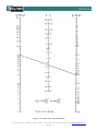
1
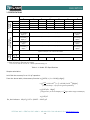
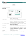
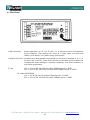
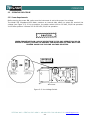
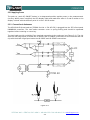
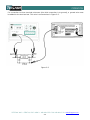
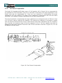
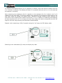
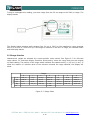
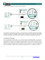
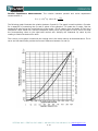
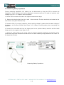
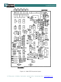
252 General Purpose, Portable Impedance/LCR Meter MODEL 252 Instruction Manual PN# 252-840 Publication Date: January 2012 Rev. L NOTE: This User’s Manual was as current as possible when this product was manufactured. However, products are constantly being updated and improved. To ensure you have the latest documentation, refer to www.tegam.com. 10 TEGAM WAY • GENEVA, OHIO 44041 • 440-466-6100 • FAX 440-466-6110 • [email protected] 252 10 TEGAM WAY • GENEVA, OHIO 44041 • 440-466-6100 • FAX 440-466-6110 • [email protected] TABLE OF CONTENTS TABLE OF CONTENTS 1 DESCRIPTION 1.1 INTRODUCTION ..............................................................................................1-1 1.2 SPECIFICATIONS .............................................................................................1-2 2 OPERATION 2.1 CONTROLS AND CONNECTORS..........................................................................2-1 2.1.1 Front Panel ......................................................................................2-1 2.1.2 Rear Panel ........................................................................................2-2 2.2 OPERATING PROCEDURE ...................................................................................2-3 2.2.1 Power Requirements .........................................................................2-3 2.2.2 Applying Power ................................................................................2-4 2.2.3 Connection to Unknowns ..................................................................2-4 2.2.3.1 Test Fixture Compensation ....................................2-6 2.2.4 Function Selection ...........................................................................2-7 2.2.5 Range Selection ...............................................................................2-10 2.2.6 Summary of Operation .....................................................................2-11 2.3 MEASUREMENT TECHNIQUES ............................................................................2-12 2.3.1 Resistance Measurements at 1 kHz ....................................................2-12 2.3.2 Capacitance Measurements ................................................................2-12 2.3.3 Inductance Measurements .................................................................2-15 2.3.4 Determining Quality Factor (Q) of Inductors ......................................2-15 2.3.5 Determining Dissipation Factor (D) of Capacitors using Nomograph ..............................................................2-16 2.3.6 Using the Bias Feature ......................................................................2-18 2.3.7 Signal Output Terminals ....................................................................2-19 2.3.8 Measuring Grounded Unknowns .........................................................2-19 2.3.9 Measuring Battery Impedance ...........................................................2-21 3 CIRCUIT DESCRIPTION 3.1 GENERAL DESCRIPTION .................................................................................3-1 4 MAINTENANCE 4.1 CALIBRATION PROCEDURE ............................................................................4-1 4.1.1 Power Supply Check ............................................................................4-2 4.1.2 Oscillator Adjust ..................................................................................4-2 4.1.3 L, C, R, G Alignment ............................................................................4-2 4.1.4 Dissipation Factor (D) Alignment ...........................................................4-3 10 TEGAM WAY • GENEVA, OHIO 44041 • 440-466-6100 • FAX 440-466-6110 • [email protected] I TABLE OF CONTENTS TABLE OF CONTENTS (continued) 4.2 MAINTENANCE..............................................................................................4-5 4.2.1 Preventive Maintenance .......................................................................4-5 4.2.1.1 Cleaning ..........................................................................................4-5 4.2.1.2 Visual Inspection ..............................................................................4-5 4.3 PREPARATION FOR CALIBRATION OR REPAIR SERVICE .....................................4-6 4.4 WARRANTY ..................................................................................................4-8 Appendix A (for 252/SP2596) Instrument Description .............................................................................A-1 Performance Specifications ........................................................................A-2 Battery Removal/Replacement ...................................................................A-3 DANGEROUS VOLTAGE POTENTIALS EXIST INSIDE THIS INSTRUMENT. MAINTENANCE INSTRUCTIONS WITHIN THIS MANUAL ARE FOR USE BY QUALIFIED SERVICE PERSONNEL ONLY. TO AVOID ELECTRICAL SHOCK, DO NOT ATTEMPT ANY SERVICING OTHER THAN THAT CONTAINED IN THE OPERATION INSTRUCTIONS UNLESS YOU ARE QUALIFIED TO DO SO. 10 TEGAM WAY • GENEVA, OHIO 44041 • 440-466-6100 • FAX 440-466-6110 • [email protected] II DESCRIPTION SECTION 1 DESCRIPTION 1.1 INTRODUCTION Model 252 Digital Impedance/LCR Meter is a semi-automatic instrument which permits rapid measurement of inductance (L), capacitance (C), resistance (R), conductance (G) and dissipation factor (D) at a test frequency of 1 kHz. Measurement accuracy and versatility satisfies most demanding engineering or scientific applications. To operate, merely push the button for the desired function, manually turn the knob to the desired range, and connect the unknown. KELVIN KLIPS® test leads are included, thus ensuring true fourterminal connections. The position of the range switch, used in conjunction with the desired function button and front panel range scale, indicate the unit of measurement being displayed by the 3½ digit LED readout. Excellent reliability of the Model 252 Impedance/LCR Meter is assured through use of solid-state devices and etched circuit board construction. Its small size is ideal for use on bench tops where work space may be at a premium. The carrying handle tilts the unit to a convenient viewing angle. Rear panel brackets provide line cord storage and enable it to be operated in a vertical position. 10 TEGAM WAY • GENEVA, OHIO 44041 • 440-466-6100 • FAX 440-466-6110 • [email protected] 1-1 DESCRIPTION 1.2 SPECIFICATIONS Full Scale Values Ranges 0 1 2 3 Ls 200 µH 2 mH 20 mH 200 mH 2H 20 H 200 H Cp 200 pF 2 nF 20 nF 200 nF 2 µF 20 µF 200 µF 5 6 Rs 2Ω 20 Ω 200 Ω 2000 Ω 20 kΩ 200 kΩ 2000 kΩ Gp 2 µS 20 µS 200 µS 2000 µS 20 mS 200 mS 2000 mS D Ls Cp Accuracy (15°C to 35°C) 4 Rs Gp 1.999 ±(0.25% + (1+0.002Rs*) digits)** ±(0.25% + (1+0.002Gp*) digits)** ±(0.25% + (1+0.002Ls*) digits) ±(0.25% + (1+0.002Cp*) digits) D ±(0.25% + (1+0.001Rs*) digits) ±(0.25% + (1+0.010Rs*) digits) ±(0.25% + (1+0.010Gp*) digits) ±(0.25% + (1+0.010Ls*) digits) ±(0.25% + (1+0.010Cp*) digits) ±(0.25% + (1+0.001Gp*) digits) ±(0.25% + (1+0.001Ls*) digits) ±(0.25% + (1+0.001Cp*) digits) ±(1%+0.002) for L or C ≥ 200 counts ±(2%+0.010) for L or C 50 to 199 counts 0.1 VRMS Test Signal Voltage 1.0 VRMS Cp, Gp Current 100 mA 10 mA 1 mA 100 µA Ls, Rs *Digit Count, same range. ** After correction for test lead zero reading. 0 °C to 15 °C and 35 °C to 50 °C : add 0.1(rated accuracy)/°C 10 µA 1 µA Table 1-1. Model 252 Specifications Sample calculation: Let’s find the accuracy for a 100 µF capacitor. ] From the above table, the accuracy formula is = ] ( ) = ] ( = So, the limits are 10 TEGAM WAY • GENEVA, OHIO 44041 • 440-466-6100 • FAX 440-466-6110 • [email protected] 1-2 DESCRIPTION Test Frequency: 1 kHz ± 1%. Unknown Excitation: The 1 kHz voltage (Vx) and current (Ix) levels listed in Table 1-1 are held constant by an internal amplitude control circuit. Measurement Rate: Four per second; one second is required for first reading after connecting unknown to terminals. Measurement Display: 3½ digit LED with decimal point. Blanked for overload conditions. Unit Display: Unit of mesurement being displayed by the LED readout is indicated by position of the range switch, used in conjunction with the desired function button and the front panel range scale. External Bias: Rear panel terminals are provided for connection of external supply. 0 V to 50 VDC, 0.1 A maximum. (Read Section 2.3.6 before using external bias.) Static Charge Protection: Diode and resistor discharge network. Connection to Unknown: Four-terminal, shielded, connections are provided by the KELVIN KLIPS® cable assembly (TEGAM Part No.# CA-162-36) supplied with the Model 252. Outputs: Analog signals of 1 V per 1,000 counts, 1 kΩ source resistance is available at rear panel. L, C, R, or G, with simultaneous output of D for L or C. Power Consumption: 4 W typical. Power Requirements: 100 to 125 VAC or 200 to 250 VAC, 50/60 Hz. Fuse: 110 V: 1/16 A 250 VAC 3AG Slow-Blow TEGAM Part No. # 8952 220 V: 1/20 A 250 VAC 5x20 mm Slow-Blow* TEGAM Part No. # 53327 * denotes that carrier adapter (TEGAM Part No. # 45965) is needed to use a 5x20 mm fuse For model 252/SP2596, 110 V: 1/8 A 250 VAC Slow-Blow TEGAM Part No. # 50028 220 V: 1/16 A 250 VAC 3AG Slow-Blow TEGAM Part No. # 8952 Size: Height (with feet) – 100 mm (4 in.) Width – 260 mm (10 in.) Depth (overall) – 370 mm (14.6 in.) Weight: 3.2 kg (7 lb.) Accessories supplied with Model 252: KELVIN KLIPS® Four-Terminal Clips Instruction Manual Socket, 0.062” Crimp, Molex 02-06-5106 Pin, 0.062” Crimp, Molex 02-06-6103 TEGAM Part No. CA-162-36 252-840 062-261 062-263 Options Available: 4-Terminal Kelvin Chip Tweezers Kelvin Klip replacement kit Front Panel Dust Cover Chip Tweezer Rebuild Kit TEGAM Part No. 2005B/SP5132 KK100 43374 47422 10 TEGAM WAY • GENEVA, OHIO 44041 • 440-466-6100 • FAX 440-466-6110 • [email protected] 1-3 OPERATION SECTION 2 OPERATION 2.1 CONTROLS AND CONNECTORS 2.1.1 Front Panel Figure 2-1. Model 252 Front Panel 1. ON/OFF Switch A push-on, push-off switch for applying and removing power from the instrument. 2. UNKNOWN Connector Terminals designed to be used with KELVIN KLIPS® test leads (TEGAM Part No. # CA-162-36), provided with Model 252, to provide a true four-terminal connection to the unknown or test fixture. 3. L, R, C, and G Pushbuttons Function pushbuttons select the type of meter circuit that will measure series inductance (L) and resistance (R) or parallel capacitance (C) and conductance (G). 4. D Pushbutton The push-to-read D (dissipation factor) pushbutton displays the D of a capacitor or inductor when the C or L function is selected. 5. Range Switch Selects the decimal multiplier and units of measurement for the meter circuit being used. The basic multipliers and units are: H (henrys), mH (millihenrys), µH (microhenrys), nF (nanofarads), kΩ (kilohms), Ω (ohms), S (siemens), mS (millisiemens), µS (microsiemens) and D (dissipation factor). 6. Display A 3½ digit readout for all functions. 7. Tilt-stand Handle Aids portability; tilts instrument for easier viewing of the LED display. 10 TEGAM WAY • GENEVA, OHIO 44041 • 440-466-6100 • FAX 440-466-6110 • [email protected] 2-1 OPERATION 2.1.2 Rear Panel Figure 2-2. Model 252 Rear Panel 1. Bias Terminals Allows application of a 2 V to 50 VDC, 0.1 A maximum bias to the capacitor being measured. (The shorting bar must be in place when not using bias feature.) See Section 2.3.6 before using external bias. 2. Output Terminals Provides two analog signals proporational to the function selected (L, R, C, or G) and D (for L and C). These terminals can be used with external DVM’s (for increased full scale readings or resolution capability), with chart recorders, or with limits comparators. 3. Fuse 110 V: 1/16 A 250 VAC 3AG Slow-Blow TEGAM Part No. # 8952 220 V: 1/20 A 250 VAC 5x20 mm Slow-Blow TEGAM Part No. # 53327 For model 252/SP2596, 110 V: 1/8 A 250 VAC Slow-Blow TEGAM Part No. # 50028 220 V: 1/16 A 250 VAC 3AG Slow-Blow TEGAM Part No. # 8952 10 TEGAM WAY • GENEVA, OHIO 44041 • 440-466-6100 • FAX 440-466-6110 • [email protected] 2-2 OPERATION 2.2 OPERATING PROCEDURE 2.2.1 Power Requirements Before turning the power ON, make sure the instrument is set to the proper line voltage. The Model 252 Impedance/LCR Meter contains an internal slide switch to select the nominal line voltage (see Figure 2-3). In its up position, the switch selects 100 to 125 VAC, 50/60 Hz operation. In the down position it selects 200 to 250 VAC, 50/60 Hz operation. WHEN CHANGING FROM 110 VAC OPERATION TO 220 VAC OPERATION (OR IN OPPOSITE ORDER), BE SURE TO REPLACE THE REAR PANEL AC FUSE WITH THE PROPER VALUE FOR THE LINE VOLTAGE SELECTED. Figure 2-3. Line Voltage Switch 10 TEGAM WAY • GENEVA, OHIO 44041 • 440-466-6100 • FAX 440-466-6110 • [email protected] 2-3 OPERATION 2.2.2 Applying Power The push-on, push-off, ON/OFF button in its depressed position applies power to the measurement circuitry. When power is applied, the LED display lights and reads zero when in C and G modes or the display is blank with the decimal point lit in the L and R modes. 2.2.3 Connection to Unknowns The KELVIN KLIP® test lead set (TEGAM Part No. # CA-162-36) is plugged into the 252’s front panel UNKNOWN connector. The test leads connector cover is spring-locking and should be squeezed together before inserting or removing. The test leads provide a shielded, four-terminal connection to the unknown (see Figure 2-4). The clip with the red hinge-spool provides the HI DRIVE and HI SENSE connections to the unknown and the clip with the black hinge-spool make the LO DRIVE and LO SENSE connections. Figure 2-4. 10 TEGAM WAY • GENEVA, OHIO 44041 • 440-466-6100 • FAX 440-466-6110 • [email protected] 2-4 OPERATION For connection to three terminal unknowns (the third connection is to ground), a ground wire must be added to the test lead set. This wire is connected as in Figure 2-5. Figure 2-5 10 TEGAM WAY • GENEVA, OHIO 44041 • 440-466-6100 • FAX 440-466-6110 • [email protected] 2-5 OPERATION 2.2.3.1 Test Fixture Compensation The Model 252 Impedance/LCR Meter uses a 3.3 pF capacitor (C6 in Figure 2-6) to compensate for the capacitance of the test leads. If the 252 is used with a test fixture, the larger capacitance of the fixture must also be compensated for. There are two methods for compensating this larger capacitance. The first method is to make a zero capacitance measurement with the test fixture connected. This reading is mentally subtracted from all other measurements. The second method for compensating the larger capacitance is to change the value of C6 from 3.3 pF to 10 pF and to add an external trim capacitor. The external trim capacitor is connected in parallel with the unknown and should be of such a value that the test fixture capacitance can be trimmed to zero. Typically, the maximum value of this trim capacitor is 15 pF. The trim capacitor can either be added to the test cable, between Terminals 1 and 3 of the connector as shown in Figure 2-6, or it can be added to the test fixture. Figure 2-6. Test Fixture Compensation 10 TEGAM WAY • GENEVA, OHIO 44041 • 440-466-6100 • FAX 440-466-6110 • [email protected] 2-6 OPERATION 2.2.4 Function Selection Model 252 Impedance/LCR Meter is designed to measure series inductance (L), parallel capacitance (C), series resistance (R), parallel conductance (G), and dissipation factor (D) of inductance and capacitance. One of these measurement modes is selected by depressing the proper front panel button. (If all buttons are in their out position, the instrument reverts to the inductance measurement mode.) Example: Select the capacitance measurement function. (Depress the C pushbutton.) 10 TEGAM WAY • GENEVA, OHIO 44041 • 440-466-6100 • FAX 440-466-6110 • [email protected] 2-7 OPERATION Example: Select the conductance measurement function. (Depress the G Pushbutton.) If a negative sign appears on the display when measuring an unknown, possible causes are: • “C” button has been pushed when measuring an inductor. • “L” button has been pushed when measuring a capacitor. • The unknown is more capacitive (or inductive) than suspected. For example, an Inductor that resonates below 1 kHz will measure as though it were a capacitor. • A diode requires bias voltage (a negative reading may appear if bias voltage is not applied). 10 TEGAM WAY • GENEVA, OHIO 44041 • 440-466-6100 • FAX 440-466-6110 • [email protected] 2-8 OPERATION To measure the dissipation factor (D) of a capacitor or inductor, push and hold the D button while the C or L function is selected. (The display will blank if D is pushed, while the unit is in R or G mode and the unknown is resistive). When measuring the conductance (G) of a capacitor or the resistance (R) of an inductor, the R or G reading may be quite small. In trying to acquire more resolution by moving the range switch to the next lower range, the display will usually blank, indicating overload. Blanking occurs because the instrument is still monitoring the reactive component (L or C) in addition to measuring and displaying the loss component (R or G). In moving to the next lower range, the reactive component becomes too large for the lower range causing overload and a blanked display. Example: while measuring a 0.82 µF capacitor using the 2 µF range, the 252 display reads: Switching to the conductance (G) mode, the display may read: 10 TEGAM WAY • GENEVA, OHIO 44041 • 440-466-6100 • FAX 440-466-6110 • [email protected] 2-9 OPERATION Trying to investigate this reading, you down range from the 20 ms range to the 2000 µs range. The display blanks: The display blanks because while ranging from 20 ms to 2000 µs, the capacitance range changed from 2 µF to 200 nF. Since 0.82 µF is too large to measure on the 200 nF range, an overload occurs and the display blanks. 2.2.5 Range Selection Measurement ranges are selected by a seven-position rotary switch. See Figure 2-7 for full-scale range values. For maximum display resolution and accuracy, select the range that gives the largest on-scale reading. The position of the range switch indicates the readout units (i.e. μH, mH, H, etc.). If either the reactive or resistive value of the unknown exceeds the range selected, the display will blank. Full Scale Values Ranges Ls Cp Rs Gp D 0 200 H 200 pF 2 2 S 1 2 mH 2 nF 20 20 S 2 20 m H 20 nF 200 200 S 3 200 m H 200 nF 2k 2 mS 1.999 Figure 2–7. Range Chart 4 2H 2 F 20 k 20 m S 5 20 H 20 F 200 k 200 m S 6 200 H 200 F 2000 k 2000 m S Figure 2–7. Range Chart 10 TEGAM WAY • GENEVA, OHIO 44041 • 440-466-6100 • FAX 440-466-6110 • [email protected] 2-10 OPERATION Example: Set the instrument to measure 100pF capacitors. Example: Set the instrument to measure 100kΩ resistors. If the value of a component is not known, set the instrument to its highest range before connecting the test leads. Step the instrument down one range at a time until the range with the highest resolution is reached. If the display is blank after the component is connected, the value of the component is too large to measure directly, see Section 2.3 for alternate measurement techniques. 2.2.6 Summary of Operation Press the appropriate function button (L, C, or G) and connect the KELVIN KLIPS® to the unknown. For maximum accuracy, select the range that gives the largest on-scale reading. The measurement is displayed after one second or less. Repetitive measurements are made at the rate of four per second. The position of the range switch indicate the readout units (i.e. µH, mH, H, etc.). If the value of the unknown exceeds the range selected, the display will remain blanked. To measure the dissipation factor of a capacitor or inductor, push and hold the D button while the C or L function is selected. 10 TEGAM WAY • GENEVA, OHIO 44041 • 440-466-6100 • FAX 440-466-6110 • [email protected] 2-11 OPERATION 2.3 MEASUREMENT TECHNIQUES 2.3.1 Resistance Measurements at 1 kHz When using the resistance function, the maximum measurement is 1999 kΩ. For measurements from 1999 kΩ to 1000 MΩ, use the G (conductance) function where G=1/R or R=1/G. Measurement accuracy is determined by ± (0.25% + 1 digit) where 1 digit will be ±100% at 1000 MΩ, ±10% at 100 MΩ and ±1% at 10 MΩ. High-value, bobbin-type, wire-wound resistors have shunt capacitance which may affect measurements by appearing as “-Ls”. This causes some difference between AC and DC resistance measurement values. The resistive component (Rs) of inductors and transformers, when measured at 1 kHz, will differ from the DC winding resistance. If the core material is air or low loss (e.g. powdered permalloy), the AC and DC values will be nearly equal. For laminated magnetic cores, the AC resistance will be greater than the winding resistance (sometimes much greater). This is caused by the core losses which change both with frequency and test current level. 2.3.2 Capacitance Measurements Shielded devices. For shielded devices, the shield should be connected to the rear panel –Bias terminal to provide proper guarding. Most two- and four-terminal cables or sorting fixtures are not guarded immediately adjacent to where the unknown capacitor is connected, and a zero capacitance reading can change by a few picofarads whenever the ends of the cable or fixture terminals are physically moved. Always maintain the physical orientation of the leads or terminals after checking for zero capacitance. Subtract zerocapacitance reading from the capacitance reading for the unknown. 10 TEGAM WAY • GENEVA, OHIO 44041 • 440-466-6100 • FAX 440-466-6110 • [email protected] 2-12 OPERATION Equivalent Series Resistance (ESR). To measure series resistance of capacitors, use the Rs function. Series resistance will be displayed on the front panel. Series Capacitance. The Ls function can be used to measure series capacitance. (The capacitor is measured with a constant current rather than a constant voltage.) A negative reading will be shown and the following equation must be used to convert the “- ” readings to the “Cs” values: Where: f = frequency in hertz Cs = series capacitance in farads Ls = series inductance in henrys (ignore sign) Dissipation factor (D). The D of large value electrolytic capacitors can be determined using the Ls and Rs functions using the same range. The following equation converts the Rs and Ls, in counts (ignore the Sign and decimal point), to D values: Where: D = dissipation factor Rs = equivalent series resistance reading in counts Ls = series inductance in counts 10 TEGAM WAY • GENEVA, OHIO 44041 • 440-466-6100 • FAX 440-466-6110 • [email protected] 2-13 OPERATION Parallel Capacitance Measurements. The relation between parallel and series capacitance measurements is: The following graph illustrates the relation between Cs and Cp. The graph is used to obtain a Cs value for a capacitor by measuring the Cp and D values of the capacitor. To locate the Cs value, find the measured D value along the horizontal axis of the graph. (The D reading from the Model 252 will be a Dissipation Factor value not a Percent Dissipation value.) Move up the graph to the B curve and read the corresponding value on the right-hand vertical axis. Multiply the measured Cp value by this reading to obtain the desired Cs value. The A curve on the graph is used with the vertical axis in the same manner as described above. The A curve and left-hand scale provide the Percent Difference between Cs and Cp. 10 TEGAM WAY • GENEVA, OHIO 44041 • 440-466-6100 • FAX 440-466-6110 • [email protected] 2-14 OPERATION 2.3.3 Inductance Measurements The Model 252 Impedance/LCR Meter measures the total impedance connected to its terminals. Both the unknown inductor and its leads contribute to this impedance. The leads have some resistance and inductance which affect the value read from the meter. In making high inductance measurements, avoid AC pickup and keep the stray capacitance to a minimum. To minimize both effects, keep hands as far as possible from the inductor being measured. Keep the leads as short and direct as possible. Take care to avoid coupling stray magnetic fields into the inductor. For greatest accuracy on low inductance measurements, minimize the lead impedance. Closely spaced, twisted leads will reduce the inductance and pickup of stray fields. The KELVIN KLIPS® Cable Assembly will add about 0.5 µH to Ls and 0 mΩ to Rs. Short the tests leads together and subtract the reading from the unknown inductance measured. Measuring leakage inductance of transformer windings is an easy task for the Model 252 since there are no “false nulls” as found in manually-balanced bridges. 2.3.4 Determining Quality Factor (Q) of Inductors To determine the Q of inductors, push the D button, record the D reading and calculate Q from the equation Q=1/D. This procedure works well for Q ≥ 0.5 (or D ≤ 2). For Q ≤ 0.5, measure the inductance of the unknown and record the readout display in digits only. With the RANGE switch in the same position, press the R button and note the readout display in digits, only. Do not record the decimal point or range multiplier for Ls or Rs; they are not required. Turn to Figure 2-8 for the D-Q nomograph. Use a straightedge to line up the Ls digits recorded (left-hand scale) with the Rs digits recorded (right-hand scale). Q is taken from the left-hand side of the center scale where the straightedge crosses. For example, with an Ls digital display of “300” and an Rs digital display of “600”, Q is 0.3. Accuracy of Q is primarily limited by interpolation of the nomograph. Although the nomograph provides a convenient way to approximate Q, it may be determined more accurately by the formula: Where: Q = Quality factor Rs = equivalent series resistance reading in counts Ls = series inductance in counts See Table 1-1 for accuracy of Ls and Rs measurements. 10 TEGAM WAY • GENEVA, OHIO 44041 • 440-466-6100 • FAX 440-466-6110 • [email protected] 2-15 OPERATION 2.3.5 Determining Dissipation Factor (D) of Capacitors Using Nomograph Model 252 will measure dissipation factor up to 1.999. For D values greater than 2 the nomograph should be used. Measure the capacitance of the unknown and record the readout display in digits only; do not record the decimal point. With the RANGE switch left in the same position, push the G button and note the readout display in digits only; do not record the decimal point. Turn to Figure 2-8 for the D-Q nomograph. Use a straightedge to line up the Cp digits recorded (left-hand scale) with the Gp digits recorded (right-hand scale). D is taken from the right-hand side of the center scale where the straightedge crosses. For example, with a Cp digital display of “200” and a Gp digital display of “300”, D is 2.3. Accuracy of D is primarily limited by interpolation of the nomograph. Dissipation factor may be determined more accurately by the formula: Where: D = dissipation factor Gp = parallel conductance reading in counts Cp = parallel capacitance in counts See Table 1-1 for accuracy of Cp and Gp measurements. Electrolytic capacitors with high dissipation are usually unstable and the measured values may drift. 10 TEGAM WAY • GENEVA, OHIO 44041 • 440-466-6100 • FAX 440-466-6110 • [email protected] 2-16 OPERATION Figure 2-8. Model 252 D-Q Nomograph 10 TEGAM WAY • GENEVA, OHIO 44041 • 440-466-6100 • FAX 440-466-6110 • [email protected] 2-17 OPERATION 2.3.6 Using the Bias Feature TO AVOID PERSONAL INJURY FROM ELECTRICAL SHOCK OBSERVE SAFETY PROCEDURES AS NEEDED FOR THE BIAS VOLTAGE APPLIED. Bias voltage is necessary or desirable when measuring the capacitance of diodes or of some electrolytic or tantalum capacitors. There is a provision on the rear panel for connecting an external bias source of zero to 50 VDC. Remove the shorting link between BIAS terminals when using this feature. If the external bias supply is not a low AC impedance type, it should have a capacitor bypass of five times the range full-scale value connected across the bias terminals. The bias supply should be current limited to 0.1 A maximum. With no bias supply connected, the rear-panel + and – terminals must be strapped together. Figure 2-9. Rear Panel 10 TEGAM WAY • GENEVA, OHIO 44041 • 440-466-6100 • FAX 440-466-6110 • [email protected] 2-18 OPERATION 2.3.7 Signal Output Terminals Terminals are provided on the Model 252’s rear panel for connecting external devices: digital voltmeters to increase full-scale resolution or simultaneous D reading; chart recorders to evaluate unknowns with changing impedances; limits comparators for HI, LO, GO, and HI D component sorting. The analog output signals are proportional to the function selected (L, C, R, or G) and D (for L and C only). Specifications for these signals are: Scale Factor Source Resistance Accuracy 1 V per 1000 counts 1000 Ω ± (0.25% of reading + 1 mV) 2.3.8 Measuring Grounded Unknowns The model 252 is designed to measure ungrounded components. However, with a minor modification, it can be used to measure impedances that are connected directly or tightly coupled to earth ground. TO AVOID PERSONAL INJURY FROM ELECTRIC SHOCK DO NOT REMOVE INSTRUMENT COVERS OR PERFORM ANY MAINTENANCE OTHER THAN DESCRIBED IN THIS MANUAL. INSTALLATION AND MAINTENANCE PROCEDURES DESCRIBED IN THIS MANUAL ARE TO BE PERFORMED BY QUALIFIED SERVICE PERSONNEL ONLY. The modification of instruments is as follows: 1. Locate the connector strip on the rear panel (see Figure 2-10). 2. Remove and isolate the spade lug from the terminal marked COM. Figure 2-10 10 TEGAM WAY • GENEVA, OHIO 44041 • 440-466-6100 • FAX 440-466-6110 • [email protected] 2-19 OPERATION To make measurements of grounded unknowns, connect the grounded side of the unknown to the KELVIN KLIPS® with the red insulating hinge-spool and the ungrounded end to the clip with the black spool (see Figure 2-11). Figure 2-11 A small zero offset may become apparent during low value grounded capacitance measurements. This offset can be corrected by making a reading with the unknown connected only to the red clips and subtracting it from the final measured capacitance. To return to normal ungrounded measurements reverse the above procedures. 10 TEGAM WAY • GENEVA, OHIO 44041 • 440-466-6100 • FAX 440-466-6110 • [email protected] 2-20 OPERATION 2.3.9 Measuring Battery Impedance Current producing capabilities of a battery can be determined by using the 252 to measure its impedance. Series resistance and series capacitance measurements can be made on batteries with voltages up to 50 V. To measure series resistance: 1. Set the 252 to measure Rs and to the highest measurement range. 2. Remove the shorting bar from the + and – bias terminals. The bias terminals are located on the instrument’s rear panel terminal strip. 3. Connect a 500 µF (or larger) capacitor, whose working voltage is greater than the rated voltage of the battery, to the bias terminals (see Figure 2-12). Observe correct polarity when connecting the capacitor. 4. Connect the test leads with the red hinge-spool to the positive battery terminal and the black hinge-spool to the negative (see Figure 2-12). 5. Move the range switch to the range with the highest resolution displayed (see Section 2.2.5) unless that range uses excessive test current for the size of battery being measured. See Table 1-1 for range test currents. Figure 2-12. Measuring Battery Impedance 10 TEGAM WAY • GENEVA, OHIO 44041 • 440-466-6100 • FAX 440-466-6110 • [email protected] 2-21 OPERATION The Ls function must be used to measure the series capacitance of a battery. Instrument set up is the same as for Rs measurements (Figure 2-11). A negative reading will be shown, and the following equation must be used to convert the “-Ls” reading to “+Cs” values: Where: f = frequency in hertz Cs = series capacitance in farads Ls = series inductance in henrys Care must be taken so the measurement current level of the 252’s internal source does not exceed the rating of the battery being tested. See Table 1-1 for range test currents. 10 TEGAM WAY • GENEVA, OHIO 44041 • 440-466-6100 • FAX 440-466-6110 • [email protected] 2-22 CIRCUIT DESCRIPTION SECTION 3 CIRCUIT DESCRIPTIONS 3.1 GENERAL DESCRIPTION When measuring Cp or Gp, a voltage is applied across the unknown and range resistor in Figure 3-1. The voltage across the unknown is held constant to within one part in several thousand by the 1 kHz oscillator feedback control circuit. A current proportional to the value of the unknown impedance is produced through the range resistor. The resultant voltage drop across the range resistor is separated into two vector components by the Phase Sensitive Detectors (PSD) and Reference Voltage Generator (RVG). Receiving gating signals from RVG, the PSD will measure Gp, the component in phase (0°) with RVG, and Cp, the component at quadrature (90°). The selected detector output is then fed to the A/D Converter which has a readout of 1000 counts/volt. When measuring Ls or Rs, a voltage is applied across the unknown and range resistor in Figure 3-1. The voltage across the range resistor is held constant to within one part in several thousand by the 1 kHz oscillator feedback control circuit. With a constant current flowing through the unknown, a voltage proportional to the value of the unknown impedance is developed across the unknown. The resultant voltage drop is separated into two vector components by the Phase Sensitive Detector (PSD) and Reference Voltage Generator (RVG). Receiving gating signals from the RVG, the PSD will measure Rs, the component in phase (0°) with the RVG, and Ls, the component at quadrature (90°). The selected detector output is then fed to the A/D Converter which has a readout of 1000 counts/volt. 10 TEGAM WAY • GENEVA, OHIO 44041 • 440-466-6100 • FAX 440-466-6110 • [email protected] 3-1 CIRCUIT DESCRIPTION Figure 3-1. Model 252 Simplified Diagram When measuring the dissipation factor (D) of inductors or capacitors, an analog ratio circuit is used. This circuit compares the loss component (Rs or Gp) to the reactive component (Ls or Cp) and presents a voltage proportional to D to the A/D Converter. Analog output voltages are available at the rear of Model 252 for the selected function (L, C, R or G) and simultaneous D (for L or C unknowns). 10 TEGAM WAY • GENEVA, OHIO 44041 • 440-466-6100 • FAX 440-466-6110 • [email protected] 3-2 MAINTENANCE SECTION 4 MAINTENANCE TO AVOID PERSONAL INJURY FROM ELECTRIC SHOCK DO NOT REMOVE INSTRUMENT COVERS OR PERFORM ANY MAINTANCE OTHER THAN DESCRIBED IN THIS MANUAL. INSTALLATION AND MAINTENANCE PROCEDURES DESCRIBED IN THIS MANUAL ARE TO BE PERFORMED BY QUALIFIED SERVICE PERSONNEL ONLY. 4.1 CALIBRATION PROCEDURE Although Model 252 is inherently stable, good maintenance practices suggest it be calibrated every six months; more often if used in extreme environments or if inaccurate readings are suspected. Equipment Required Minimum Specifications Frequency Counter Measure 1000 Hz with resolution of 1 Hz Digital Voltmeter Resolution of 100 µVDC Resistance Standard 1000 Ω ±0.05%, non-inductive. Capacitance Standard 100 nF, ±0.05%, silvered mica or polystyrene Dissipation Factor Standards 1 µF Decade Capacitor, 5 dial, polystyrene, D<0.0002; 10 µF polystyrene capacitor with D known to ±0.001; 100 µF capacitor with D known to ±0.001 KELVIN KLIPS® FourTerminal Clips TEGAM Part No. # CA-162-36 Refer to Figure 4-1 for adjustment locations. 10 TEGAM WAY • GENEVA, OHIO 44041 • 440-466-6100 • FAX 440-466-6110 • [email protected] 4-1 MAINTENANCE 4.1.1 Power Supply Check Setup – Turn on instrument and allow ten minute warm-up period; then remove cover. Check power supply voltages at C44 and C45 should be + and –5 V ± 5% (4.75 V to 5.25 V). Use rear panel COM terminal for voltmeter low input. 4.1.2 Oscillator Adjust Setup – Press R function button. Set RANGE switch to 2000 ohms and short test leads together. Connect voltmeter high input to Test Socket (J5) pin (2) and frequency counter input to J5 pin (1). Use rear panel COM terminal for circuit common. Adjustment – Set trimmer S for DVM reading of 0 V (± 0.2 V). Counter reading should be 1000 Hz (± 10 Hz). 4.1.3 L,C,R,G Alignment 1. R, G PHASE DETECTOR ZERO TRIM. Setup – Press R function button and set RANGE switch to 2000 Ω and short test leads together. Connect DVM input to J5 pin (6). Adjustment – Set trimmer P for 0mV ± 0.1 mV on DVM. 2. UNKNOWN AMP COMMON MODE TRIM. Setup – Press R function button and set RANGE switch to 2 Ω and short test leads together. Adjustment – Adjust trimmer J for DVM reading of 0 V ± 0.3 mV at J5 pin (6). 3. L, C PHASE DETECTOR ZERO TRIM. Setup – Press L function button and set RANGE switch to 200 mH. Short test leads together and connect DVM input to J5 pin (5). Adjustment – Set trimmer M for 0mV ± 0.1 mV on DVM 4. L, C, R, G OUTPUT AMP ZERO TRIM. Setup – Same as step 3 except connect DVM input to J5 pin (4). Adjustment – Set trimmer V for 0 V ± 0.3 mV on DVM. 5. UNKNOWN AND RANGE AMP PHASE TRIM. Setup – Press C function button and set RANGE switch to 200 nF. Connect decade capacitor to unknown test leads and set at 160 nF (± 5%). Adjustment – Note voltage at J5 pin (6) and then push L function button, again noting J5 pin (6) voltage. The two should be equal (± 0.3 mV). If not, adjust trimmer X until they are. Next adjust trimmer D for 0V ±0.3mV output at J5 pin (6) for both L and C functions. 6. QUADRATURE GATE PHASE TRIM. Setup – Press R function button and set RANGE switch to 2000 Ω. Connect 1000 Ω (± 0.05%) standard to unknown test leads. Adjustment – Set trimmer L for DVM reading of 0V ± 0.3 mV at J5 pin (5). 7. R, G FULL SCALE TRIM. Setup – Same as step 6. Adjustment – Set trimmer K for front panel digital reading of 1000. With DVM, read voltage at J5 pin (4) and adjust trimmer R for +1.0 V (± 0.5 mV). 8. L, C FULL SCALE TRIM. Setup – Press C function button and set RANGE switch to 200 nF. Connect 100 nF (± 0.05%) standard to the unknown test leads. Adjustment – Set trimmer N for front panel reading of 1000. 10 TEGAM WAY • GENEVA, OHIO 44041 • 440-466-6100 • FAX 440-466-6110 • [email protected] 4-2 MAINTENANCE 4.1.4 Dissipation Factor (D) Alignment 1. LOW LEVEL ZERO TRIM. Setup – Press C function button and set RANGE switch to 200 nF. Connect a low loss (D<0.0002) decade capacitor to unknown test leads. Adjustment – Set the decade capacitor to 105 nF and, with a DVM, note the voltage at J5 pin (3) or D output terminal at the rear panel. Set the decade to 5 nF and again note the voltage. If the two voltages are not equal (± 1 mV), adjust trimmer W until switching between 105 nF and 5 nF produces equal readings. 2. HIGH LEVEL ZERO TRIM. Setup – Same as step 1. Adjustment – Set decade capacitor to 100 nF and adjust trimmer U until voltage at J5 pin (3) or D output is 0 V ± 0.3 mV. 3. D FULL SCALE TRIM. Setup – Same as step 1. Adjustment – Set the decade capacitor for a front panel C reading of 159.2 nF. Connect the 1000 Ω standard resistor in parallel with the decade capacitor. Set trimmer T for a front panel D reading (push D button) of 1.000. 4. 200 pF RANGE D TRIM. Setup – Press C function button and set RANGE switch to 200 pF. Connect the low loss (D<0.0002) decade capacitor to unknown test leads. Adjustment – Set the decade to 100pF (± 20%) and adjust trimmer H for 0V ± 0.3 mV at J5 pin (3), or D output. 5. 2 nF RANGE D TRIM. Setup – Same as step 4, except set RANGE switch to 2 nF. Adjustment – Set decade to 1 nF (± 20%) and adjust trimmer F for 0V ± 0.3 mV at J5 pin (3), or D output. 6. 20 nF RANGE D TRIM. Setup – Same as step 4, except set RANGE switch to 20 nF. Adjustment – Set decade to 10nF (± 20%) and adjust trimmer E for 0 V ± 0.3 mV at J5 pin (3), or D output. 7. 2 µF RANGE D TRIM. Setup – Same as step 4, except set RANGE switch to 2 µF. Adjustment – Set decade to 1 µF (± 20%) and adjust trimmer C for 0 V ± 0.3 mV at J5 pin (3), or D output. 8. 20 µF RANGE D TRIM. Setup – Set RANGE switch to 20 µF and connect a 10 µF (± 20%) capacitor (D known to ± 0.001) to unknown test leads. Adjustment – Adjust trimmer B for front panel D reading (push D button) equal to D value of the 10 µF capacitor. 9. 200 µH RANGE D TRIM. Setup – Press the L function switch and set the RANGE switch to 200 µH. Short the Kelvin Klips together and note the zero inductance (approximately +5 counts) for use in the adjustment. Connect a 1.2 Ω, 5% carbon composition resistor to the test leads. Adjustment – Adjust trimmer A for a display equal to, or –1 count from the zero inductance value noted when the Kelvin Klips were shorted together. 10 TEGAM WAY • GENEVA, OHIO 44041 • 440-466-6100 • FAX 440-466-6110 • [email protected] 4-3 MAINTENANCE Figure 4-1. Model 252 Component Layout 10 TEGAM WAY • GENEVA, OHIO 44041 • 440-466-6100 • FAX 440-466-6110 • [email protected] 4-4 MAINTENANCE 4.2 MAINTENANCE This section of the manual contains maintenance information for use in preventative maintenance, corrective maintenance, and troubleshooting of the Model 252. 4.2.1 Preventative Maintenance REMOVAL OF INSTRUMENT COVERS MAY CONSTITUTE AN ELECTRICAL HAZARD AND SHOULD BE ACCOMPLISHED BY QUALIFIED SERVICE PERSONNEL ONLY. Preventive maintenance performed on a regular basis will improve the reliability of this instrument. It may include cleaning, visual inspection, or even monitoring the operating environment. 4.2.1.1 Cleaning AVOID THE USE OF CHEMICAL CLEANING AGENTS WHICH MIGHT DAMAGE THE PLASTICS USED IN THIS UNIT. DO NOT APPLY ANY SOLVENT CONTAINING KETONES, ESTERS OR HALOGENATED HYDROCARBONS. TO CLEAN, USE ONLY WATER SOLUBLE DETERGENTS, ETHYL, METHYL, OR ISOPROPYL ALCOHOL. Exterior. Loose dust may be removed with a soft cloth or a dry brush. Water and mild detergent may be used; however, abrasive cleaners should not be used. Interior. Use low-velocity compressed air to blow off the accumulated dust. Hardened dirt can be removed with a cotton-tipped swab, soft, dry cloth, or a cloth dampened with a mild detergent and water. 4.2.1.2 Visual Inspection This instrument should be inspected occasionally for defects such as broken connections, improperly seated semiconductors, damaged circuit boards and heat-damaged parts. The corrective procedure for most visible defects is obvious. If heat-damaged components are found, particular care must be taken. Overheating usually indicates other trouble in the instrument. It is important that the cause of overheating be corrected to prevent recurrence of the damage. 10 TEGAM WAY • GENEVA, OHIO 44041 • 440-466-6100 • FAX 440-466-6110 • [email protected] 4-5 MAINTENANCE 4.3 Preparation for Calibration or Repair Service: No user serviceable parts are available for this equipment. If a problem arises and you have verified that the cause for malfunction cannot be solved in the field then the instrument should be sent to TEGAM for service. Before sending a unit in for service, an RMA, (Returned Material Authorization), number must be assigned to your instrument. You can contact TEGAM customer service via the TEGAM website, www.tegam.com or calling 440.466.6100 or 800.666.1010. The RMA number is unique to your instrument and will help us identify you instrument and to address the particular service request by you which is assigned to that RMA number. Of even importance, a detailed written description of the problem should be attached to the instrument. Many times repair turnaround is unnecessarily delayed due to a lack of repair instructions or of a detailed description of the problem. This description should include information such as measurement range, and other instrument settings, type of components being tested, are the symptoms intermittent?, conditions that may cause the symptoms, has anything changed since the last time the instrument was used?, etc. Any detailed information provided to our technicians will assist them in identifying and correcting the problem in the quickest possible manner. Use a copy of the Repair and Calibration Service form provided on the next page. Once this information is prepared and sent with the instrument to our service department, we will do our part in making sure that you receive the best possible customer service and turnaround time possible. 10 TEGAM WAY • GENEVA, OHIO 44041 • 440-466-6100 • FAX 440-466-6110 • [email protected] 4-6 MAINTENANCE Expedite Repair & Calibration Form Use this form to provide additional repair information and service instructions. The Completion of this form and including it with your instrument will expedite the processing and repair process. RMA#: Serial Number: Technical Contact: Additional Contact Info: Instrument Model #: Company: Phone Number: Repair Instructions: Evaluation Calibration Only Repair Only Repair & Calibration Z540 (Extra Charge) Detailed Symptoms: Include information such as measurement range, instrument settings, type of components being tested, is the problem intermittent? When is the problem most frequent?, Has anything changed with the application since the last time the instrument was used?, etc. 10 TEGAM WAY • GENEVA, OHIO 44041 • 440-466-6100 • FAX 440-466-6110 • [email protected] 4-7 MAINTENANCE 4.4 Warranty TEGAM, Inc. warrants this product to be free from defects in material and workmanship for a period of one year from the date of shipment. During this warranty period, if a product proves to be defective, TEGAM Inc., at its option, will either repair the defective product without charge for parts and labor, or exchange any product that proves to be defective. TEGAM, Inc. warrants the calibration of this product for a period of 6 months from date of shipment. During this period, TEGAM, Inc. will recalibrate any product, which does not conform to the published accuracy specifications. In order to exercise this warranty, TEGAM, Inc., must be notified of the defective product before the expiration of the warranty period. The customer shall be responsible for packaging and shipping the product to the designated TEGAM service center with shipping charges prepaid. TEGAM Inc. shall pay for the return of the product to the customer if the shipment is to a location within the country in which the TEGAM service center is located. The customer shall be responsible for paying all shipping, duties, taxes, and additional costs if the product is transported to any other locations. Repaired products are warranted for the remaining balance of the original warranty, or 90 days, whichever period is longer. Warranty Limitations The TEGAM, Inc. warranty does not apply to defects resulting from unauthorized modification or misuse of the product or any part. This warranty does not apply to fuses, batteries, or damage to the instrument caused by battery leakage. The foregoing warranty of TEGAM is in lieu of all other warranties, expressed or implied. TEGAM specifically disclaims any implied warranties of merchantability or fitness for a particular purpose. In no event will TEGAM be liable for special or consequential damages. Purchaser’s sole and exclusive remedy in the event any item fails to comply with the foregoing express warranty of TEGAM shall be to return the item to TEGAM; shipping charges prepaid and at the option of TEGAM obtain a replacement item or a refund of the purchase price. Statement of Calibration This instrument has been inspected and tested in accordance with specifications published by TEGAM Inc. The accuracy and calibration of this instrument are traceable to the National Institute of Standards and Technology through equipment, which is calibrated at planned intervals by comparison to certified standards maintained in the laboratories of TEGAM Inc. Contact Information: TEGAM INC. 10 TEGAM WAY GENEVA, OHIO 44041 CAGE Code: 49374 WEB: http://www.tegam.com 10 TEGAM WAY • GENEVA, OHIO 44041 • 440-466-6100 • FAX 440-466-6110 • [email protected] 4-8 252/SP2596 General Purpose, Portable Impedance/LCR Meter (With Battery option) MODEL 252/SP2596 Appendix A 10 TEGAM WAY • GENEVA, OHIO 44041 • 440-466-6100 • FAX 440-466-6110 • [email protected] TABLE OF CONTENTS TABLE OF CONTENTS Instrument Description .............................................................................A-1 Performance Specifications .......................................................................A-2 Battery Removal/Replacement .................................................................A-3 10 TEGAM WAY • GENEVA, OHIO 44041 • 440-466-6100 • FAX 440-466-6110 • [email protected] INSTRUMENT DESCRIPTION INSTRUMENT DESCRIPTION The Model 252/SP2596 is a battery powered model 252 Digital Impedance/LCR meter. A rechargeable battery pack has been added to enhance the portability feature of the model 252. Basic instrument operation remains unchanged, and the specifications listed in the instruction manual are valid. Additional specifications and support information for the battery operated model is provided in this document. This instrument will operate with either battery power or AC line power. (The batteries do not have to be charged to operate with AC power.) The duration for battery-powered operation depends on the measurement range and the type of measurement involved. It will operate 4 to 5 hours (minimum, continuous) at maximum current drain, or 8 to 12 hours under normal operating conditions. Low battery power is signaled by the instrument’s display blinking ON/OFF when battery power drops below 4.1 VDC. The battery can be brought to full charge by leaving the instrument plugged in overnight, or for approximately 15 hours. The full charge point is 5.7 VDC. 10 TEGAM WAY • GENEVA, OHIO 44041 • 440-466-6100 • FAX 440-466-6110 • [email protected] A-1 INSTRUMENT DESCRIPTION PERFORMANCE SPECIFICATIONS Battery Requirement: 4 AA NiMH batteries rated at 2300 mAh. TEGAM Part No. #57695 4 C NiMH batteries rated at 2500 mAh. TEGAM Part No. #57694 Power Requirements: 100 to 125 VAC / 200 to 250 VAC, 50/60 Hz, 4 W or battery power Fuses: +5 V battery supply 3 A @ 32 V, AGW, Fast Blow, TEGAM Part No. # 41003 -5 V battery supply 1 A @ 32 V, 7AG, Fast Blow, TEGAM Part No. # 57696 Operating Time: Dependent of range and type of measurement. 4 to 5 Hours minimum with maximum current drain; typically, 8 to 12 hours, continuous operation. Charging Time: Approximately 15 hours for full charge. Full Charge Level: 5.7 VDC. After prolonged storage, 3 to 5 cycles of full chargedischarge may be needed to achieve full capacity. Battery Low Indicator: The 3½ digit display blinks ON and OFF when battery voltage is <4.1 VDC. Display will blink for about 15 minutes then blank. 10 TEGAM WAY • GENEVA, OHIO 44041 • 440-466-6100 • FAX 440-466-6110 • [email protected] A-2 BATTERY REMOVAL/REPLACEMENT BATTERY REMOVAL/REPLACEMENT FOR QUALIFIED SERVICE PERSONNEL ONLY ! SERVICING SAFETY SUMMARY Use Care When Servicing with Power On Dangerous voltages may exist at several points in this product. To avoid personal injury or damage to this equipment, avoid touching exposed connections or components while the power is on. Assure that the power is off when removing panels, soldering, or replacing components. TO AVOID PERSONAL INJURY FROM ELECTRIC SHOCK, DO NOT REMOVE INSTRUMENT COVERS OR PERFORM ANY MAINTENANCE OTHER THAN DESCRIBED IN THIS MANUAL. INSTALLATION AND MAINTENANCE PROCEDURES DESCRIBED ARE TO BE PERFORMED BY QUALIFIED SERVICE PERSONNEL ONLY. ! BATTERIES INSTALLED WITH THE WRONG POLARITY MAY DAMAGE THE INSTRUMENT AND DEGRADE THE LIFE OF THE BATTERY. OPERATOR SHOULD WEAR A GROUNDING WRIST WRAP WHILE PERFORMING THE BATTERY REPLACEMENT. The 252/SP2596 requires that 4 AA and 4 C size NiMH batteries be installed for battery powered operation. Follow the step by step procedure provided below to replace the batteries: Step 1. Turn instrument power OFF. Remove the AC power connection. Step 2. Remove the rear panel screws holding the top cover. Step 3. Slide the cover off toward the rear and set aside. Step 4. Lift off the clear plastic protection shield from the battery supply. Step 5. Remove and replace the old batteries. Be careful to install them in proper polarity. Refer to figure 1. Step 6. Reinstall the protection shield and put the cover back on. 10 TEGAM WAY • GENEVA, OHIO 44041 • 440-466-6100 • FAX 440-466-6110 • [email protected] A-3 BATTERY REMOVAL/REPLACEMENT Figure 1: Rechargeable Battery Installation 10 TEGAM WAY • GENEVA, OHIO 44041 • 440-466-6100 • FAX 440-466-6110 • [email protected] A-4 252/SP2596 Contact Information: TEGAM INC. 10 TEGAM WAY GENEVA, OHIO 44041 CAGE Code: 49374 WEB: http://www.tegam.com 10 TEGAM WAY • GENEVA, OHIO 44041 • 440-466-6100 • FAX 440-466-6110 • [email protected]


![[ENG-ITA] User's Manual UPS EVO DSP PLUS MM 1.2-2.4](http://vs1.manualzilla.com/store/data/006884869_1-f09fb11d812c485aa10a235685fba597-150x150.png)