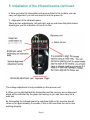
1
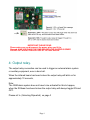
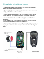
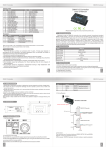
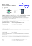
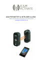
GSM PERIMETER & INTRUDER ALARM
Our GSM Perimeter and Intruder alarm system can be used for
indoor and outdoor purposes, the transmitter and receiver can be
placed up to 100 metres outdoors and 300 metres indoors placing
two invisible beams between each other, when the beams are
broken it will trigger the alarm and using the GSM technology it will
send you a text message or phone call to your mobile phone or
land line to alert you.
· GSM Frequency: Quad band Freq 850/900/1800/1900
MHz
· Power Supply Voltage: 12 24 Vdc2 Amp max
· Current used in standby mode: 25 ma max
· IP Enclosure rating for outside installation
· 3 Amp Relay output
· Standard 2G simcard
· No Landline Required
· Dimensions L175 xW100 xH90mm Transmitter
· Dimensions L175 xW100 xH100mm Receiver
· Operating Temperature: -10...+40°C
· Sensor range 100m outdoors, 300m indoors
· Auto•reset
· Dipswitch setting for call or text alert
· Text for signal strength
· Stay Active Sim Function
· Ta b le o f c o n te n ts
1: setting up the gsm module
2: Fitting the simcard
3: Selecting the dipswich Text/Phone call
4: Relay output
5: Installation of the infrared beams
6: Programming the gsm alarm module
P age 2
1 : S e ttin g u p th e G S M
A la rm M o d u le
New simcards will need registering before they can be used. Full details of
how to do this can normally be found in the simcard pack. It will usually
require that the simcard is inserted into a mobile phone, a number dialled and
instructions followed.
While the SIM is in the mobile phone it would be a good time to disable any
PIN codes, call diverts, ring back and disable features such as voicemail and
text alerts. details of how to do this is found on the simcard provider’s web
site or by calling their customer services. Please use one of the following SIM
card providers (Vodafone, TMobile, O2/, Giff Gaff, or Orange, EE,) we do not
recommend the “three” network.
Please note the GSM Perimeter and Intruder alarm has a built in “sim active
function” which keeps track of the unit ’s activity and if there has been no
usage for 6 weeks it will send out a text message to a preset recorded number
to keep the simcard alive, this then eliminates the problems of simcards being
shut down if they are unused for 3 months.
2: F ittin g th e s im c a rd
(Ref to page 4)
1: Slide back the sim door and lift it up.
2: slide the simcard in to the door making sure that the clipped corner of the
simcard lines up with the clipped corner of the sim holder.
3: Close the sim door.
4: Slide the sim door to lock the simcard in place.
3: S e le c tin g D ip s w itc h .
(Ref to page 4)
Dipswitch 1 OFF
If you select Dip s w itc h 1 to O FF position and the infrared beam has been
triggered the unit will send you a text message. (A la r m Tr ig g e r e d )
Dipswitch 1ON
If you select Dip s w itc h 1 to O N position and the infrared beam has been
triggered you will receive a telephone call alert.
After six ring tones the call will automatically hang up, you do not need to
Answer the call.
Dipswitch 2 OFF
If you select Dip s w itc h 2 to O FF position the alarm output relay will trigger
for 10 sec every time the beam is broken, regardless if the alarm has been
switched ON or OFF.
Dipswitch 2 ON
If you select Dip s w itc h 2 to O N position the alarm output relay will only trigger
when the beam is broken and the alarm is turned ON.
P ag e 3
IM P O R TA N T P LE A S E R E A D
P le a s e m a k e s u re y o u d is c o n n e c t th e p o w e r w h e n y o u fit th e
S im c a r d .A N D Y O U P LA CE THE S IM CA R D W ITH THE CLIP P E D CO R N E R
FA CIN G O U T W A R DS P LE A S E LO O K A T P ICTU R E A B O V E .
4: Output relay.
The output relay connection can be used to trigger an external alarm system
or auxiliary equipment, even a door bell.
When the infrared beam has been broken the output relay will latch on for
approximately 10 seconds,
Note:
The GSM alarm system does not have to be activated for this to happen,
when the IR Beam has been broken the output relay will always toggle ON and
OFF.
Please ref to (Selecting Dipswitch) on page 3
P ag e 4
5: Installation of the infrared beams
1: Find a suitable location for the transmitter and receiver and ensure the
sensors are mounted on a stable structure,
2: When installing the receiver take care to position the receiver out of direct
sunlight, as this will reduce the sensitivity.
3: Ensure the sensors line of sight is free from false alarm sources such as
bushes, trees, etc. Pay attention to these they may change seasonally.
4: It is important to have the correct Power Supply to operate this device
successfully.
You will need a 12 volt 2 Amp supply or 12 volt battery, you can purchase
both of these from the website www.gsm-activate.co.uk
5: Below is a photograph of how to connect the transmitter and receiver, if you
are going to use the relay alarm output you will need to refer to the diagram
Below.
P ag e 5
5: Installation of the infrared beams continued
6: Now you have the transmitter and receiver fitted to the location you can
carry out alignment, you will now need to turn the power on.
7: Alignment of the infrared beams.
There are two adjustments, left and right, and up and down the photo below
should give you the indication of how to do this.
The voltage adjustment is only available on the receiver unit
8: When you’re satisfied that the transmitter and the receiver are in alignment,
which will be indicated by the green led turning on you can then carry out a
walk test.
By interrupting the infrared beam the red alarm light on the receiver should
come on for approximately 4 seconds, if this is the case then the unit is now
working properly.
P ag e 6
6 : P ro g ra m in g th e G S M
A la rm M o d u le
You are now ready to start programming the GSM module, this will
allow the unit to send a Text message or phone call, depending on
how you set the unit up, but first you need to program the simcard with the
telephone numbers maximum 3 numbers.
E x a m p le :
(Ha s h )(1 o r 2 o r 3 )(S ta r ) (p h o n e n u m b e r ) (s ta r )
#1*01798123456*
Then send this as a text to the simcard
#2*01798856323*
#3*01798898765*
Max 3 numbers.
N o te : Y o u c a n o n ly s e n d o n e n u m b e r a t a tim e ,it is im p o r ta n t to w a it
u n til y o u r e c e iv e a te x t a c k n o w le d g e m e n t S TO R E D b e fo r e s e n d in g th e
s e c o n d n u m b e r .Th is m a y ta k e s o m e tim e d e p e n d in g o n h o w b u s y y o u r
n e tw o r k is .
If you wish to cancel a number follow this example.
(Ha s h ) (1 o r 2 o r 3 )(S ta r )(S ta r )
#1**
Then send this as a text to the simcard.
Below is a notepad to help you remember the names and numbers that you
have saved to your simcard, in the event you need to modify or delete In the
future.
#1* ________________________*
#2* ________________________*
#3* ________________________*
Now you have the simcard programmed please make sure that you have set
Dipswitch 1 to ON if you would like it to make a phone call to you.
Dipswitch 1 OFF if you would prefer to Receive a text message.
P ag e 7
7: H o w to tu rn o n th e A la rm M o d u le
At this point to turn on the alarm you simply send a text message command
#A c tiv a te to the alarm it will send you a text message acknowledgement back.
A la r m o n .
To switch off the alarm send the text command
#De a c tiv a te .
When the alarm has been triggered it will revert to standby. To reactivate the
alarm you will need to send the #A c tiv a te command again
A la r m o u tp u t r e la y
This is a dry contact relay which can be used to activate auxiliary equipment or
external alarm systems,
The relay has a COM & N/O contacts @3Amp Load (max)
S ig n a l s tr e n g th
To help make sure that you place the unit in a suitable position you can text
the unit to see how much signal strength you have, by texting
#S S this will indicate the strength of the signal, you will receive a text telling
you if it’s good, average, poor, signal, we strongly recommend that you place
the unit where you can get at least average signal, you will find that with a poor
signal it will be unreliable and is not suitable.
3 metre signal booster cable is available from our sales department
Telephone - 0800 772 0783 or for technical support - 0800 2461583
Email - [email protected]
Web - www.gsm-activate.co.uk
Qu i ck r e f e r e n ce
Se n d T e x t
#Activate
#Deactivate
#SS
#1*1 2 3 4 5 6 7 9 9 8 9 *
#1**
Op e r a t i o n
Turn Alarm on
Turn Alarm off
Check signal st r engt h
To st ore phone num ber 1
To delete phone num ber 1
V1_08032015
P age 8
A ckn o wl e d g me n t
Alarm on
Alar m off
Good, Av e, Poor
St ored
Deleted